EP3149280B1 - Turbinenschaufel mit optimierten kühlkanälen - Google Patents
Turbinenschaufel mit optimierten kühlkanälen Download PDFInfo
- Publication number
- EP3149280B1 EP3149280B1 EP15729543.7A EP15729543A EP3149280B1 EP 3149280 B1 EP3149280 B1 EP 3149280B1 EP 15729543 A EP15729543 A EP 15729543A EP 3149280 B1 EP3149280 B1 EP 3149280B1
- Authority
- EP
- European Patent Office
- Prior art keywords
- blade
- duct
- downstream
- upper cavity
- cavity
- Prior art date
- Legal status (The legal status is an assumption and is not a legal conclusion. Google has not performed a legal analysis and makes no representation as to the accuracy of the status listed.)
- Active
Links
Images



Classifications
-
- F—MECHANICAL ENGINEERING; LIGHTING; HEATING; WEAPONS; BLASTING
- F01—MACHINES OR ENGINES IN GENERAL; ENGINE PLANTS IN GENERAL; STEAM ENGINES
- F01D—NON-POSITIVE DISPLACEMENT MACHINES OR ENGINES, e.g. STEAM TURBINES
- F01D5/00—Blades; Blade-carrying members; Heating, heat-insulating, cooling or antivibration means on the blades or the members
- F01D5/12—Blades
- F01D5/14—Form or construction
- F01D5/18—Hollow blades, i.e. blades with cooling or heating channels or cavities; Heating, heat-insulating or cooling means on blades
-
- B—PERFORMING OPERATIONS; TRANSPORTING
- B22—CASTING; POWDER METALLURGY
- B22C—FOUNDRY MOULDING
- B22C9/00—Moulds or cores; Moulding processes
- B22C9/10—Cores; Manufacture or installation of cores
- B22C9/103—Multipart cores
-
- F—MECHANICAL ENGINEERING; LIGHTING; HEATING; WEAPONS; BLASTING
- F01—MACHINES OR ENGINES IN GENERAL; ENGINE PLANTS IN GENERAL; STEAM ENGINES
- F01D—NON-POSITIVE DISPLACEMENT MACHINES OR ENGINES, e.g. STEAM TURBINES
- F01D5/00—Blades; Blade-carrying members; Heating, heat-insulating, cooling or antivibration means on the blades or the members
- F01D5/12—Blades
- F01D5/14—Form or construction
- F01D5/18—Hollow blades, i.e. blades with cooling or heating channels or cavities; Heating, heat-insulating or cooling means on blades
- F01D5/186—Film cooling
-
- F—MECHANICAL ENGINEERING; LIGHTING; HEATING; WEAPONS; BLASTING
- F01—MACHINES OR ENGINES IN GENERAL; ENGINE PLANTS IN GENERAL; STEAM ENGINES
- F01D—NON-POSITIVE DISPLACEMENT MACHINES OR ENGINES, e.g. STEAM TURBINES
- F01D5/00—Blades; Blade-carrying members; Heating, heat-insulating, cooling or antivibration means on the blades or the members
- F01D5/12—Blades
- F01D5/14—Form or construction
- F01D5/18—Hollow blades, i.e. blades with cooling or heating channels or cavities; Heating, heat-insulating or cooling means on blades
- F01D5/187—Convection cooling
-
- F—MECHANICAL ENGINEERING; LIGHTING; HEATING; WEAPONS; BLASTING
- F05—INDEXING SCHEMES RELATING TO ENGINES OR PUMPS IN VARIOUS SUBCLASSES OF CLASSES F01-F04
- F05D—INDEXING SCHEME FOR ASPECTS RELATING TO NON-POSITIVE-DISPLACEMENT MACHINES OR ENGINES, GAS-TURBINES OR JET-PROPULSION PLANTS
- F05D2220/00—Application
- F05D2220/30—Application in turbines
- F05D2220/32—Application in turbines in gas turbines
-
- F—MECHANICAL ENGINEERING; LIGHTING; HEATING; WEAPONS; BLASTING
- F05—INDEXING SCHEMES RELATING TO ENGINES OR PUMPS IN VARIOUS SUBCLASSES OF CLASSES F01-F04
- F05D—INDEXING SCHEME FOR ASPECTS RELATING TO NON-POSITIVE-DISPLACEMENT MACHINES OR ENGINES, GAS-TURBINES OR JET-PROPULSION PLANTS
- F05D2230/00—Manufacture
- F05D2230/20—Manufacture essentially without removing material
- F05D2230/21—Manufacture essentially without removing material by casting
- F05D2230/211—Manufacture essentially without removing material by casting by precision casting, e.g. microfusing or investment casting
-
- F—MECHANICAL ENGINEERING; LIGHTING; HEATING; WEAPONS; BLASTING
- F05—INDEXING SCHEMES RELATING TO ENGINES OR PUMPS IN VARIOUS SUBCLASSES OF CLASSES F01-F04
- F05D—INDEXING SCHEME FOR ASPECTS RELATING TO NON-POSITIVE-DISPLACEMENT MACHINES OR ENGINES, GAS-TURBINES OR JET-PROPULSION PLANTS
- F05D2250/00—Geometry
- F05D2250/70—Shape
- F05D2250/75—Shape given by its similarity to a letter, e.g. T-shaped
-
- F—MECHANICAL ENGINEERING; LIGHTING; HEATING; WEAPONS; BLASTING
- F05—INDEXING SCHEMES RELATING TO ENGINES OR PUMPS IN VARIOUS SUBCLASSES OF CLASSES F01-F04
- F05D—INDEXING SCHEME FOR ASPECTS RELATING TO NON-POSITIVE-DISPLACEMENT MACHINES OR ENGINES, GAS-TURBINES OR JET-PROPULSION PLANTS
- F05D2260/00—Function
- F05D2260/20—Heat transfer, e.g. cooling
- F05D2260/202—Heat transfer, e.g. cooling by film cooling
-
- F—MECHANICAL ENGINEERING; LIGHTING; HEATING; WEAPONS; BLASTING
- F05—INDEXING SCHEMES RELATING TO ENGINES OR PUMPS IN VARIOUS SUBCLASSES OF CLASSES F01-F04
- F05D—INDEXING SCHEME FOR ASPECTS RELATING TO NON-POSITIVE-DISPLACEMENT MACHINES OR ENGINES, GAS-TURBINES OR JET-PROPULSION PLANTS
- F05D2260/00—Function
- F05D2260/20—Heat transfer, e.g. cooling
- F05D2260/204—Heat transfer, e.g. cooling by the use of microcircuits
-
- F—MECHANICAL ENGINEERING; LIGHTING; HEATING; WEAPONS; BLASTING
- F05—INDEXING SCHEMES RELATING TO ENGINES OR PUMPS IN VARIOUS SUBCLASSES OF CLASSES F01-F04
- F05D—INDEXING SCHEME FOR ASPECTS RELATING TO NON-POSITIVE-DISPLACEMENT MACHINES OR ENGINES, GAS-TURBINES OR JET-PROPULSION PLANTS
- F05D2260/00—Function
- F05D2260/20—Heat transfer, e.g. cooling
- F05D2260/221—Improvement of heat transfer
-
- Y—GENERAL TAGGING OF NEW TECHNOLOGICAL DEVELOPMENTS; GENERAL TAGGING OF CROSS-SECTIONAL TECHNOLOGIES SPANNING OVER SEVERAL SECTIONS OF THE IPC; TECHNICAL SUBJECTS COVERED BY FORMER USPC CROSS-REFERENCE ART COLLECTIONS [XRACs] AND DIGESTS
- Y02—TECHNOLOGIES OR APPLICATIONS FOR MITIGATION OR ADAPTATION AGAINST CLIMATE CHANGE
- Y02T—CLIMATE CHANGE MITIGATION TECHNOLOGIES RELATED TO TRANSPORTATION
- Y02T50/00—Aeronautics or air transport
- Y02T50/60—Efficient propulsion technologies, e.g. for aircraft
Definitions
- the invention relates to a turbine blade for an aircraft engine of the turbomachine type, such as a turbojet or a turboprop.
- outside air is admitted through an inlet sleeve to pass through a fan having a series of rotating blades before splitting into a central primary flow and a secondary flow surrounding the primary flow.
- the primary flow is then compressed before entering a combustion chamber, after which it expands through a set of turbines before being exhausted to the rear, generating thrust.
- the secondary flow is propelled directly to the rear by the fan to generate additional thrust.
- Each turbine consists of a succession of stages, each comprising a series of radially oriented blades regularly spaced around an engine rotation shaft.
- This central shaft carries the rotating elements of the turbine as well as the rotating elements of the compressor and the fan.
- the turbine blades which are subjected to the most severe conditions are those of the first expansion stages of this turbine, namely the stages closest to the combustion zone and which are commonly called high pressure stages.
- This cooling is ensured by circulating fresh air inside these blades, which is taken from the turbojet upstream of the combustion.
- This air is admitted at the base of the blade, to travel along an internal circuit of the blade in order to cool it, and it is evacuated from the blade by holes passing through the wall of this blade and distributed on this wall. These holes are used to evacuate the cooling air, but they also create on the external surface of the blade a film of air colder than the air from the combustion, which also helps to limit the temperature of the blade.
- the interior regions of the blade through which the cooling air circulates have artifices, i.e., internal reliefs which disturb the fluid flow of the cooling air to increase the heat transfer from the blade wall to this cooling air circulating in the internal ducts of the blade.
- the aim of the invention is to propose a blade structure making it possible to improve the cooling efficiency of this blade.
- the invention relates to a turbomachine turbine blade and molding means for manufacturing such a blade, as defined in the claims.
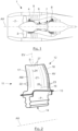
- a front part of a dual-flow turbojet 1 comprises an inlet sleeve 2 into which the air is admitted before being sucked in by the blades of a fan 3. After passing the region of the fan, the air divides into a central primary flow and a secondary flow which surrounds the primary flow.
- the primary air flow then passes through a first compressor 4 located immediately after the blower 3 while the secondary flow is propelled towards the rear to directly generate additional thrust by being blown around the primary flow.
- the primary flow then passes through a second compression stage 6, before reaching a chamber 7 where its combustion takes place, after injection and vaporization of a fuel. After combustion, this primary flow expands in a high pressure turbine 8 then in a low pressure turbine not shown to drive the compression stages and the fan in rotation, before being expelled towards the rear of the engine to generate thrust.
- the engine 1 and its components have a shape of revolution around a longitudinal axis AX. It comprises in particular an external casing 9 also having a shape of revolution and extending from the front of the engine where it delimits the air intake sleeve, to the rear part where it delimits the duct through which the primary and secondary flows are evacuated, the front and the rear to be considered relative to the direction of advance of the aircraft equipped with this turbojet.
- This casing 9 supports the rotating components located at the center of the engine and which include a rotating shaft carrying the fan blades as well as the compression stages and the turbine with their blades.
- Such a dawn which is marked by 11 on the Figure 2 , comprises a foot P by which it is fixed to a rotating body not shown, called a turbine disk, and a blade 12 carried by this foot P and constituting the aerodynamic part of this blade.
- the blade 11 comprises between the root P and the blade 12 an intermediate region 13 called platform.
- the assembly formed by the foot P and the blade 12 is a single, hollow, single-piece cast piece comprising internal ducts through which cooling air circulates. These internal ducts, not visible in the Figure 2 have intake vents opening on the lower face 14 of the foot P and through which these conduits are supplied with fresh air.
- the hollow wall of the blade 12 has through holes and slots through which the cooling air is evacuated.
- the blade 12 has a twisted left shape with a substantially rectangular outline, approaching a parallelepiped. It comprises a base 16 by which it is connected to the root P and which extends approximately parallel to the axis of rotation AX. It also comprises a leading edge 17 oriented radially relative to the axis AX and located at the upstream AM of the blade, that is to say the front region of this blade, relative to the direction of advancement of the engine which it equips in service. This blade also comprises a trailing edge 18 oriented approximately parallel to the leading edge 17 while being spaced from it along the axis AX to be located at the downstream region AV or rear of the blade. It also comprises a peak S approximately parallel to the base 16 and spaced from it in a radial direction relative to the axis AX.
- the two main walls of this dawn are its intrados wall 21, which is the wall visible in the Figure 2 , and its extrados wall which is the opposite wall spaced from the intrados wall, and which is not visible in the Figure 2 because it is masked by the intrados wall 21.
- the intrados and extrados walls are joined at the leading edge 17, at the trailing edge 18 and also in the region of the tip S of this blade. These walls are spaced from each other at the base 16 to allow the admission of cooling air into the internal region of the blade.
- the leading edge 17 has a curved shape and is provided with a series of cooling holes 22 passing through the wall of the blade in this region.
- the trailing edge 18 has a tapered shape and comprises a series of cooling slots 23. These slots 23 are short slots extending along the span direction and which are spaced apart from each other while being located in the extension of each other at a short distance from the trailing edge.
- Each slot 23 passes through the wall of the blade to take cooling air from inside this blade and blow it onto the intrados wall at the trailing edge.
- the trailing edge is provided with external ribs oriented parallel to the axis AX to channel the cooling air coming from these slots.
- the fluid in which this blade 11 is located moves relative to it from the leading edge 17 to the trailing edge 18 along the intrados 21 and the extrados.
- the intrados wall which is subjected to a significant heating in operation, comprises a series of holes 24 substantially parallel to the leading edge 17 while being located downstream of this leading edge, and another series of holes 26 substantially parallel to the trailing edge 18 while being located upstream of this trailing edge 18 and the slots 23 which it comprises.
- the series of holes 24 and 26 thus extend one and the other in the span direction EV of the blade, which is the radial direction relative to the axis AX.
- the region of the tip S of the blade 11 has, unlike the leading edge 17 and the trailing edge 18, a certain thickness, and it also has a shape delimiting a hollow portion called a bathtub.
- this summit S has a closing wall which connects the intrados and extrados walls, this closing wall having an orientation which is globally perpendicular to the intrados and extrados walls and parallel to the axis AX, which corresponds to an orientation perpendicular to the span direction EV.
- This closing wall which is not visible on the Figure 2 is located set back towards the axis AX relative to the free edge of the intrados wall and the free edge of the extrados wall, so that it constitutes, together with these edges, a hollow portion open in the direction opposite to the axis AX.
- a series of additional holes 27 passing through the intrados wall is provided along the apex S to ensure significant cooling of this blade apex which is subject to significant stresses due to the fact that it constitutes the part having the highest speed relative to the fluid.
- the series of holes 27 extends parallel to the closing wall, and the blade additionally includes holes not visible on the Figure 2 which pass through the closing wall to open into the hollow portion called the bathtub which is at the top of the blade.
- such a blade is a hollow one-piece part. It is manufactured by casting a metallic material, using a set of cores to delineate the internal ducts of its hollow portion as well as rod portions to form its through holes. The cores, rods and others are removed once that the molding operation is completed, typically with a chemical etching process capable of dissolving these elements without altering the molded material.
- the idea behind the invention is to improve the cooling of the blade in the region of the intrados wall which is in the vicinity of the trailing edge and the tip of the blade, since in practice this region is the first to deteriorate during the life of a blade.
- the air taken from the root thus travels directly, in a substantially straight line, to the upper cavity.
- the length of the path taken by this air, in the supply duct, for it to reach the upper cavity is thus less than or equal to the length of the blade in the span direction EV.
- this duct makes it possible to minimize the heating of the air supplied to the upper cavity.
- this supply duct is formed by a leading edge cooling ramp located upstream.
- this supply duct is constituted by a central duct of the blade, that is to say located approximately halfway between its leading edge and its trailing edge.
- the blade which is marked 31 in the Figure 3 where it is represented, thus comprises internal ducts arranged to bring into the region of the tip of the blade on the intrados side, the coolest possible cooling air so as to increase the cooling efficiency there.
- the interior of this blade 31 thus comprises in its upstream region, identified by AM, an upstream ramp 32 oriented according to its span direction EV and which runs along its leading edge.
- This upstream ramp 32 directly feeds an upper cavity 33 of the blade, while supplying fresh air to cooling holes passing through the wall portion forming the leading edge of the blade.
- This upstream ramp 32 extends from the root of the blade, identified by P, and by which it is directly supplied with air, to the top of the blade identified by S.
- the upper cavity 33 which is located near the top extends along the closing wall of this blade 31 and along its intrados wall, from the front to the rear of the blade which is identified by AV. These two walls are not visible in the Figure 3 since it is a representation of the hollow regions of this dawn.
- the upper cavity 33 reaches the trailing edge of the blade, in the downstream region AV, to supply fresh air to at least one cooling slot of this trailing edge, namely the slot closest to the tip which corresponds to one of the most severely stressed regions of the blade.
- This upper cavity 33 runs along the intrados wall, extending over a width less than the width or thickness of the blade, that is to say it has a width less than the distance separating the intrados and extrados walls. It is delimited laterally by a first face 34 which runs along the intrados and a second face 36 spaced from the first. The first face 34 and the second face 36 are joined at the front and rear of this upper cavity.
- the upper cavity 33 is delimited vertically by a bottom 37 parallel to the closing wall and spaced from it and by an upper face 38 which is the lower face of the closing wall.
- the intrados wall may comprise through holes, not shown, allowing the upper cavity 33 to additionally cool the external face of the intrados wall in this region.
- the interior of the blade 31 also includes a downstream ramp 41 extending along the trailing edge from the root P to the region of the apex S to end under the rear part of the upper cavity 33.
- This downstream ramp 41 feeds a series of trailing edge cooling slots, not visible in the Figure 3 .
- the majority of the cooling slots of the trailing edge are thus supplied with air by the downstream ramp 41, but it is the upper cavity which supplies the slot(s) closest to the apex S, which is a region subject to greater thermal stresses.
- the slots close to the apex are thus supplied with cooler air and/or having a greater flow rate than the others.
- the dawn of the Figure 3 further comprises a first central duct 42, a second central duct 43 and a downstream duct 44, oriented in the span direction, and communicating with each other in a so-called trombone arrangement.
- the first central duct 42 which runs along the upstream ramp 32 collects air at the level of the foot of the blade, and it communicates at the level of the tip S with the second central duct 43 to supply it with air.
- This second central duct 43 is connected at the base of the blade with the downstream duct 44 to supply it with air.
- This downstream duct 44 extends in a straight line from the root P to the top S, parallel to the downstream ramp 41 which it runs along while being located upstream of this downstream ramp 41.
- the end of the downstream duct 44 ends in the region of the apex S by running along the second face 36 of the upper cavity 33 to bypass it.
- the intrados wall can be provided with through holes allowing the ducts 42, 43, 44 to supply cooling air to the external face of this wall to cool it by forming an external film there.
- the intrados wall may comprise, at the level of the downstream duct 44, through holes through which this downstream duct 44 supplies air cooling the external face of the intrados wall upstream of the trailing edge of the blade.
- the downstream duct 44 can supply the downstream ramp 41 through a series of calibrated passages (not shown), regularly spaced from each other along the span direction EV. In this case, instead of being supplied by the second duct 43, the downstream duct 44 then directly collects cooling air at the level of the blade root, so that the air it supplies to the downstream ramp is as cool as possible.
- downstream ramp 41 can be supplied in a calibrated manner by the downstream conduit 44, or, on the contrary, it can be supplied directly in the region of the foot of the blade.
- passages are then calibrated to approximately achieve a desired airflow rate in each trailing edge cooling slot.
- the desired airflow rate for a given slot is conditioned by the trailing edge thermal constraints in the region cooled by that slot.
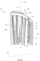
- the blade which is identified by 51 comprises an upper cavity 52 which is supplied directly by a central conduit 53 entirely dedicated to this upper cavity 52.
- the supply duct of the upper cavity does not participate in the cooling of the leading edge.
- a first lateral cavity 54 is also provided along the intrados wall, and a second lateral cavity 56 along the extrados. These two lateral cavities thermally insulate the central duct as well as an upstream duct for calibrated supply of a cooling ramp for the leading edge of the blade, the intrados and extrados walls which are heated by the gas flows surrounding the blade.
- the upper cavity 52 of this blade 51 has a shape substantially identical to that of the blade 31 of the Figure 3 . It is located near the S apex, extends along the closing and intrados walls, from the front to the rear of the blade. Here too, the entire part of the S apex located on the intrados side is supplied with air through this upper cavity 52, over substantially its entire length up to the rear end. This upper cavity 52 also extends to the trailing edge, to supply fresh air to at least the slot closest to the apex S, marked by 55, and possibly some adjacent slots.
- this upper cavity 52 is also less than the thickness of the blade. It is delimited laterally by a first face 57 which runs along the intrados and a second face 58 spaced from the first face, these faces being joined at the front and at the rear. In the vertical direction, the upper cavity 52 is delimited by a bottom 59 parallel to the closing wall, and by the lower face 61 of this closing wall.
- the intrados wall may also have through holes to cool the outer face of the intrados wall in the tip region.
- the central duct 53 feeds this upper cavity 52 by extending from the root P of the blade through which it is supplied with air, to the top of this blade, where it opens entirely into the bottom 59 of this upper cavity 52.
- the leading edge of the blade 51 is cooled by an upstream ramp 62 which extends from the base of the blade to the tip S, but which is supplied not directly by the root, but by an upstream duct 63 in a calibrated manner.
- This calibrated supply is ensured by calibrated passages 64 regularly spaced along the span direction EV of the blade and which each connect the upstream duct 63 to the upstream ramp 62.
- Each passage 64 has a calibrated diameter, that is to say chosen at the design stage to obtain in the area of the ramp 62 that it supplies a desired air flow which is conditioned by the thermal of the blade in this region.
- the first lateral cavity 54 has a small thickness, and it extends from the foot P to the region of the summit S while having a generally rectangular outline.
- This first lateral cavity 54 is ends under the upper cavity 52 so as not to cover it. It has a width sufficient to hide or cover the central conduit 53 as well as the upstream conduit 63 which runs alongside this central conduit.
- the second lateral cavity 56 also has a small thickness, and it extends from the foot P to the region of the apex S but covering the upper cavity 52.
- This second lateral cavity has a generally rectangular outline, having a sufficient width to mask or cover the central duct as well as the upstream duct 63 and the upper cavity 52 on the extrados side.
- the air which is supplied to the upper cavity 52 by the central duct 53 is kept cool during its travel in this duct, thanks to the thermal screens which the lateral cavities 54 and 56 form.
- the air which is supplied by the upstream duct 63 is also kept cool during its travel in this upstream duct.
- trailing edge cooling slot(s) located in the region of the apex S are supplied with air by the upper cavity 52.
- the other trailing edge slots, marked 67, are supplied by a downstream ramp 66 which extends from the foot P, where it is supplied directly via this foot, to the region of the apex S to terminate under the rear part of the upper cavity 52.
- the slots 67 are thus supplied with air by the downstream ramp 66, but it is the upper cavity 52 which supplies the slot(s) closest to the top S with cooler air and/or having a higher flow rate.
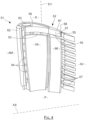
- the blade which is identified by 71 also comprises an upper cavity 72 supplied by a dedicated central duct 73 which is thermally insulated by two lateral cavities 74 and 76. These two lateral cavities also isolate an upstream duct of calibrated supply of a cooling ramp of the leading edge of the blade. But in this third embodiment, the two lateral cavities 74 and 76 are joined in the rear or downstream part of the blade to envelop this central duct 73 on three quarters of its circumference, so as to provide better thermal insulation for this conduit 73.
- the upper cavity 72 has a shape substantially identical to that of the blades of the figures 3 And 4 . It is located near the apex S, extends along the closing and intrados walls, from the front to the rear of the blade. The entire part of the apex S located on the intrados side is supplied by this upper cavity 72, over its entire length up to the rear end. This upper cavity 72 also extends to the trailing edge, to supply at least the slot closest to the apex S, marked by 75, and possibly some adjacent slots.
- this upper cavity 72 is also less than the thickness of the blade. It is delimited laterally by a first face 77 which runs along the intrados and a second face 78 spaced from the first, these faces being joined at the front and at the rear. In the vertical direction, the upper cavity 72 is delimited by a bottom 79 parallel to the closing wall, and by the lower face 81 of this closing wall. In the region of the tip S of the blade, the intrados wall may also have through holes for cooling the external face of the intrados wall in the tip region.
- the central duct 73 feeds this upper cavity 72 by extending from the foot of the blade through which it is supplied with air, to the top S, where it opens entirely into the bottom 79 of the upper cavity.
- the leading edge of the blade 71 is cooled by an upstream ramp 82 which extends from the base of the blade to the tip S, and which is supplied by an upstream duct 83 in a calibrated manner by means of calibrated passages regularly spaced along the span direction EV of the blade and which each connect the upstream duct to the upstream ramp.
- the wall of the blade has holes in the region of the leading edge, not shown, through which the air from the ramp passes through the wall to cool the external face of the leading edge.
- the first lateral cavity 74 has a small thickness and extends from the foot to the region of the apex S with a generally rectangular outline. It ends below the upper cavity 72 without covering it. It has a width sufficient to mask or cover the central conduit 73 as well as the upstream conduit 83 which runs alongside this central conduit.
- the second lateral cavity 76 also has a small thickness, and it extends from the foot to the region of the apex S but covering the upper cavity 72. It has a generally rectangular outline, having a sufficient width to mask or cover the central conduit 73 and the upstream conduit 83 and the upper cavity 72 on the extrados side.
- the two lateral cavities 74 and 76 are here joined together in the rear or downstream part instead of being separate. In this way, these two lateral cavities surround the central duct 73 over three-quarters of its circumference so as to further improve its thermal insulation from the external environment, so that it can provide the upper cavity 72 which it feeds with even cooler air.
- these two cavities are joined by a junction zone located downstream from the central duct, and which extends over the majority of the height of this central duct.
- These two cavities with their junction zone thus constitute a single cavity enveloping the central duct over the majority of its external surface.
- the height or length of the junction zone along the span direction EV corresponds to the height or length of the first lateral cavity along the span direction EV.
- the supply of these two lateral cavities can be carried out separately by two supply ducts taking the air separately from the blade root, the lateral cavities then being united only in the region of the blade. It may also be possible to provide a single supply channel for the two lateral cavities having a cross-sectional shape corresponding to that of the letter U.
- the trailing edge cooling slot(s) located in the region of the apex S are supplied with air by the upper cavity 72.
- the other trailing edge slots, marked by 86, are supplied by a downstream ramp 87 which extends from the root, where it is supplied directly via this root, to the region of the apex S to terminate under the rear part of the upper cavity 72.
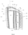
- the blade which is identified by 91 also comprises an upper cavity 92 supplied by a central duct 93 isolated by two lateral cavities 94 and 96. But in this fourth embodiment, the trailing edge is cooled by a downstream ramp which is supplied in a calibrated manner by a downstream duct.
- the upper cavity 92 has a shape substantially identical to that of the blades of the figures 3 to 5 . It is located near the apex S, extends along the closing and intrados walls, from the front to the rear of the blade. The entire part of the apex S located on the intrados side is supplied with cooling air by this upper cavity 92, over its entire length up to the rear end. This upper cavity 92 also extends to the trailing edge, to supply at least the slot closest to the apex S, marked by 95, and possibly some adjacent slots.
- This upper cavity 92 is delimited laterally by a first face 97 which runs along the intrados and a second face 98 spaced from the first, these faces being joined at the front and at the rear. It is delimited vertically by a bottom 99 parallel to the closing wall, and by the lower face 101 of this closing wall.
- the intrados wall may also have through holes for cooling the external face of the intrados wall in the apex region.
- the central duct 93 feeds this upper cavity 92 by extending from the foot of the blade by which it is supplied with air, to the apex S, where it opens entirely into the bottom 99.
- the leading edge of the blade 91 is cooled by an upstream ramp 102 which extends from the base of the blade to the tip S, being supplied by an upstream duct 103 in a calibrated manner by means of calibrated passages 105 regularly spaced along the span direction EV of the blade and which each connect the upstream duct 103 to the upstream ramp 102.
- the wall of the blade comprises, in the region of the leading edge, through holes through which the air from the ramp cools the external face of the leading edge.
- the second lateral cavity 96 also has a small thickness, and it extends from the foot to the region of the apex S but covering the upper cavity 92. It has a generally rectangular outline, of sufficient width to mask or cover the central conduit 93 and the upstream conduit 103 and the upper cavity 92 on the extrados side.
- the trailing edge cooling slot(s) located in the region of the apex S are supplied with air by the upper cavity 92.
- the other trailing edge slots, identified by 106, are supplied by a downstream ramp 107 which extends from the foot to the region of the apex S.
- This downstream ramp 107 is here supplied in a calibrated manner by a downstream duct 108 which extends from the foot of the blade to the region of its apex S where it bypasses a rear part of the upper cavity 92.
- This downstream duct 108 is located between the central duct 93 and the downstream ramp 107, and it is not masked by either the lateral cavity 94 or the lateral cavity 96.
- the downstream duct 108 supplies the downstream ramp 107 in a calibrated manner, by means of a series of calibrated passages 109 regularly spaced from one another along the span direction EV and each joining the downstream duct to the ramp 107.
- the blade which is identified by 111 also comprises an upper cavity 112 supplied by a central duct 113 isolated by two lateral cavities 114 and 116.
- the trailing edge is also cooled by a downstream ramp supplied in a calibrated manner by a downstream duct, but this downstream duct is thermally protected by lateral cavities of the blade so as to provide cooler air for cooling the trailing edge.
- the upper cavity 112 has a shape substantially identical to that of the blades of the figures 3 to 6 . It is located near the S apex, extends along the closing and intrados walls, from the front to the rear of the blade. The entire part of the S apex located on the intrados side is supplied with cooling air by this upper cavity 112, over its entire length up to the rear end. This upper cavity 112 also extends to the trailing edge, to supply at least the slot closest to the apex S, marked by 115, and possibly some adjacent slots.
- This upper cavity 112 is delimited laterally by a first face 117 which runs along the intrados and a second face 118 spaced from the first, these faces being joined at the front and at the rear. It is delimited vertically by a bottom 119 parallel to the closing wall, and by the lower face 121 of this closing wall.
- the central duct 113 feeds this upper cavity 112 by extending from the foot of the blade by which it is supplied with air, to the top S, where it opens entirely into the bottom 119.
- the leading edge of the blade 111 is cooled by an upstream ramp 122 which extends from the base of the blade to the tip S, supplied by an upstream duct 123 in a calibrated manner thanks to calibrated passages 124 regularly spaced along the span direction EV of the blade and which each connect the upstream duct 123 to the upstream ramp 122.
- the wall of the blade has through holes in the leading edge region through which the air from the ramp cools the outer face of the leading edge.
- the first lateral cavity 114 has a small thickness and extends from the root to the top region S, having a generally rectangular outline. It ends under the upper cavity 112 without covering it, and it has a width sufficient to mask or cover the central duct 113 as well as the upstream duct 123 which runs along this central duct 113, and the downstream duct for calibrated supply of the downstream ramp.
- the second lateral cavity 116 also has a small thickness, and it extends from the foot to the region of the apex S but covering the upper cavity 112. It has a generally rectangular outline, of sufficient width to mask or cover the central conduit 113, the upstream conduit 123 and the upper cavity 112 on the extrados side, as well as the downstream conduit for calibrated supply of the downstream ramp.
- the cooling slot 115 of the trailing edge located in the region of the apex S is supplied with air by the upper cavity 112.
- the other slots of the trailing edge, identified by 126, are supplied by the downstream ramp 127 which extends from the foot to the region of the apex S.
- This downstream ramp 127 is here supplied in a calibrated manner by the downstream duct 128 which extends from the foot of the blade to the region of its tip to end at the level of the tip S, bypassing the upper cavity 112.
- This downstream duct 128 is located between the central duct 113 and the downstream ramp 127.
- the downstream duct 128 supplies the downstream ramp 127 in a calibrated manner, by means of a series of calibrated passages 129 regularly spaced from one another and each joining the downstream duct 128 to the ramp 127.
- the lateral cavities 114 and 116 are here arranged to cover the upstream conduit 123, the central conduit 113 as well as the downstream conduit 128 so as to jointly cover these three elements to thermally insulate them from the intrados wall and the extrados wall.
- the blade which is identified by 131 also comprises an upper cavity 132 supplied by a central duct 133, but this is isolated by a single lateral cavity 134 located on the intrados side. This makes it possible to simplify the manufacture of the blade while providing satisfactory cooling efficiency due to the fact that in practice, the intrados wall tends to heat up significantly more than the extrados wall.
- the upper cavity 132 has a shape substantially identical to that of the blades of the figures 3 to 7 . It is located near the apex S, extends along the closing and intrados walls, from the front to the rear of the blade. The entire part of the apex S located on the intrados side is supplied with cooling air by this upper cavity 132, over its entire length up to the rear end. This upper cavity 132 also extends to the trailing edge, to supply at least the slot closest to the apex S, marked by 135, and possibly some adjacent slots.
- This upper cavity 132 is delimited laterally by a first face 137 which runs along the intrados and a second face 138 spaced from the first, these faces being joined at the front and at the rear. It is delimited vertically by a bottom 139 parallel to the closing wall, and by the lower face 141 of this closing wall.
- the central duct 133 feeds this upper cavity 132 by extending from the foot of the blade by which it is supplied with air, to the top S, where it opens entirely into the bottom 139.
- the leading edge of the blade 131 is cooled by an upstream ramp 142 which extends from the base of the blade to the tip S, which is supplied by an upstream duct 143 in a calibrated manner by means of calibrated passages 144 which are regularly spaced along the span direction EV of the blade and which each connect the upstream duct 143 to the upstream ramp 142.
- the wall of the blade has through holes in the region of the leading edge by means of which the air from the ramp cools the external face of the leading edge.
- the lateral cavity 134 has a small thickness and extends from the foot to the region of the apex S, having a generally rectangular outline. It ends under the upper cavity 132 without covering it. It has a width sufficient to mask or cover the central conduit 133 as well as the upstream conduit 143 which runs alongside this central conduit 133.
- the cooling slot 135 of the trailing edge located in the region of the apex S is supplied with air by the upper cavity 132.
- the other slots of the trailing edge, identified by 146, are supplied by a downstream ramp 147 which extends from the foot to the region of the apex S.
- This downstream ramp 147 is here supplied in a calibrated manner by a downstream conduit 148 which extends from the foot of the blade to the region of its tip to end at the level of the tip S, bypassing the upper cavity 132.
- This downstream conduit 148 is located between the central conduit 133 and the downstream ramp 147.
- the downstream conduit 148 supplies the downstream ramp 147 in a calibrated manner, by means of a series of calibrated passages 149 regularly spaced from each other along the span direction EV and each joining this downstream conduit 148 to the ramp 147.
- the lateral cavity 134 covers the upstream duct 143 as well as the central duct 133 and the downstream duct 148 so as to thermally insulate these three elements from the intrados wall to reduce the heating of the air which they carry.
- the apex region is supplied with air by the upper cavity with respect to the entire portion of the apex extending along the intrados.
- the other portions of the apex are supplied with air by the other ducts, ramps or cavities of the blade, such as in particular the upstream ramp and possibly the upstream duct, the downstream ramp and possibly the downstream duct, and where appropriate the second lateral cavity running along the extrados.
- the upper cavity has a thickness less than the thickness of the blade, i.e. the distance separating the intrados from the extrados.
- the thickness of this cavity can be reduced to less than half the thickness of the blade.
- the upper cavity makes it possible to significantly improve the cooling of the blade tip region, in particular by supplying very cool air to the trailing edge slot which is closest to the tip.
- This upper cavity also ensures cooling by thermal conduction of the blade walls which delimit it, such as for example the closing wall of the blade.
- holes passing through the walls of the blade and opening into the internal lateral cavities forming a heat shield may be provided to establish optimal air circulation in these cavities.
- Each of these holes is advantageously located at a depression zone to promote air circulation.
- Each of these holes ensures that the air collected at the base of the blade and which is conveyed into a cavity forming a heat shield, is sucked out of the blade, after having passed through this cavity.
- the cooling of the blade is further optimized by minimizing the pressure losses in each internal duct. to reduce heat exchanges, and on the contrary by providing turbulence promoters in each lateral cavity to increase heat exchanges.
- the side cavities thus have increased efficiency as a thermal screen because they absorb the heat from the external walls they run alongside, and the air circulating in the internal ducts is subject to few pressure losses in order to circulate quickly and heat up as little as possible.
- Internal ducts such as the upstream duct, the central duct and the downstream duct thus have smooth internal walls to promote rapid circulation of the cooling air by minimizing heat exchange between this air and the walls of the duct in which it travels.
- Each lateral cavity is advantageously provided with deflectors which promote air circulation in all regions of the cavity.
- the internal faces of the cavity are provided with disruptors and/or bridges to create turbulence in the circulation of the air in order to promote a high level of heat exchange between the air and the walls it passes along.
- the described blade can be made by direct manufacturing, by additive manufacturing, or by casting.
Landscapes
- Engineering & Computer Science (AREA)
- Mechanical Engineering (AREA)
- General Engineering & Computer Science (AREA)
- Turbine Rotor Nozzle Sealing (AREA)
Claims (7)
- Turbinenschaufel (51; 71; 91; 111; 131) einer Turbomaschine wie einer Propellerturbine oder eines Turbostrahltriebwerks, wobei die Schaufel ein hohles einteiligen Bauteil ist, das durch Formen hergestellt wird, wobei die Schaufel einen Fuß (P) und ein Blatt umfasst, das von dem Fuß getragen wird und sich in Spannweitenrichtung (EV) erstreckt und an einer Spitze (S) endet, wobei das Blatt eine Vorderkante und eine Hinterkante, die sich stromabwärts der Vorderkante befindet, umfasst, wobei das Blatt eine druckseitige Wand und eine saugseitige Wand umfasst, die seitlich voneinander beabstandet sind und jeweils die Vorderkante mit der Hinterkante verbinden, wobei das Blatt Folgendes umfasst:- eine Vielzahl von Kanälen (53, 63; 73, 83; 93, 103, 108; 113, 123, 128; 133, 143, 148), die dazu konfiguriert sind, Kühlluft am Fuß der Schaufel zu sammeln und diese in dem Blatt zirkulieren zu lassen, um es zu kühlen;- Löcher (22, 24, 26, 27) und/oder Schlitze (55, 67; 75, 86; 95, 106; 115, 126; 135, 146), die in ihren Wänden ausgebildet sind, um die Kühlluft aus dem Blatt abzuführen;- einen oberen inneren Hohlraum (52; 72; 92; 112; 132), der sich an der Spitze des Blatts befindet, um die Blattspitze (S) zu kühlen;wobei mindestens einer der Vielzahl von Kanälen (53; 73; 93; 113; 133) ein zentraler Kanal ist, der den oberen Hohlraum (52; 72; 92; 112; 132) direkt mit Kühlluft versorgt, die im Fuß (P) gesammelt wird, und dabei ausschließlich für das Bereitstellen von Kühlluft an den oberen Hohlraum (52; 72; 92; 112; 132) vorgesehen ist;dadurch gekennzeichnet, dass:- sie einen ersten inneren seitlichen Hohlraum (54; 74; 94; 114; 134) umfasst, der entlang der druckseitigen Wand verläuft und dabei vom Direktversorgungskanal (53; 73; 93; 113; 133) getrennt ist, um einen Hitzeschild zu bilden, der den Direktversorgungskanal (53; 73; 93; 113; 133) von der druckseitigen Wand thermisch isoliert;- sie einen zweiten inneren seitlichen Hohlraum (56; 76; 96; 116) umfasst, der entlang der saugseitigen Wand verläuft und dabei vom Direktversorgungskanal (53; 73; 93; 113) getrennt ist, um einen Hitzeschild zu bilden, der den Direktversorgungskanal (53; 73; 93; 113) von der saugseitigen Wand thermisch isoliert;- der obere Hohlraum (52; 72; 92; 112; 132) sich von der stromaufwärtigen zur stromabwärtigen Seite des Blatts erstreckt, um mindestens einen Kühlschlitz (55; 75; 95; 115; 135) der Hinterkante des Blatts zu versorgen;und dadurch, dass sie Folgendes umfasst:- eine stromaufwärts gelegene Versorgungsrampe (62; 82; 102; 122) für die Kühllöcher (22) der Vorderkante und einen stromaufwärts gelegenen kalibrierten Versorgungskanal (63; 83; 103; 123) für die stromaufwärts gelegene Rampe (62; 82; 102; 122), der durch jeden inneren seitlichen Hohlraum (54, 56; 74, 76; 94, 96; 114, 116) thermisch isoliert ist; und/oder- eine stromabwärts gelegene Versorgungsrampe (127) für die Kühlschlitze (126) der Hinterkante, die sich in der druckseitigen Wand befinden, und einen stromabwärts gelegenen kalibrierten Versorgungskanal (128) für die stromabwärts gelegene Rampe (127), der durch jeden inneren seitlichen Hohlraum (114, 116) thermisch isoliert ist.
- Schaufel (51; 71; 91; 111; 131) nach Anspruch 1, wobei die druckseitige Wand mindestens ein Durchgangsloch (27) oder einen Durchgangsschlitz (55; 75; 95; 115; 135) umfasst, das bzw. der in den oberen Hohlraum (52; 72, 92; 112; 132) mündet.
- Schaufel (51; 71; 91; 111) nach Anspruch 1 oder 2, wobei jeder innere seitliche Hohlraum (54, 56; 74, 76; 94, 96; 114, 116) mit Turbulenzpromotern und/oder Deflektoren versehen ist, um den Wärmeaustausch darin zu erhöhen, und wobei jeder Direktversorgungskanal (53; 73; 93; 113) glatte Wände aufweist, um den Druckverlust zu begrenzen.
- Schaufel (71) nach Anspruch 1, wobei die beiden inneren seitlichen Hohlräume (74, 76) durch eine Verbindungszone zusammengeführt sind, die sich stromabwärts des Direktversorgungskanals (73) befindet, um einen einzigen Hohlraum zu bilden, der drei Viertel des Umfangs des Direktversorgungskanals (73) umgibt und sich dabei über den größten Teil der Länge des Direktversorgungskanals (73) erstreckt.
- Formmittel, die dazu konfiguriert sind, eine Schaufel herzustellen, und Formhohlräume und einen Satz von Kernen umfassen, die für das Bilden der inneren Kanäle (53, 63; 73, 83; 93, 103, 108; 113, 123, 128; 133, 143, 148) der inneren seitlichen Hohlräume (54, 56; 74, 76; 94, 96; 114, 116; 134), der Rampen (62; 82; 102; 122, 127) und der Schlitze (55, 67; 75, 86; 95, 106; 115, 126; 135, 146) einer Schaufel nach einem der Ansprüche 1 bis 4 ausgelegt sind.
- Turbine einer Turbomaschine, die eine Schaufel nach einem der Ansprüche 1 bis 4 umfasst.
- Turbomaschine, die eine Turbine nach dem vorhergehenden Anspruch umfasst.
Applications Claiming Priority (2)
| Application Number | Priority Date | Filing Date | Title |
|---|---|---|---|
| FR1454864A FR3021697B1 (fr) | 2014-05-28 | 2014-05-28 | Aube de turbine a refroidissement optimise |
| PCT/FR2015/051397 WO2015181497A1 (fr) | 2014-05-28 | 2015-05-27 | Aube de turbine a refroidissement optimise |
Publications (2)
| Publication Number | Publication Date |
|---|---|
| EP3149280A1 EP3149280A1 (de) | 2017-04-05 |
| EP3149280B1 true EP3149280B1 (de) | 2025-05-14 |
Family
ID=51862381
Family Applications (1)
| Application Number | Title | Priority Date | Filing Date |
|---|---|---|---|
| EP15729543.7A Active EP3149280B1 (de) | 2014-05-28 | 2015-05-27 | Turbinenschaufel mit optimierten kühlkanälen |
Country Status (9)
| Country | Link |
|---|---|
| US (1) | US10689985B2 (de) |
| EP (1) | EP3149280B1 (de) |
| JP (1) | JP6731353B2 (de) |
| CN (1) | CN106460526B (de) |
| BR (1) | BR112016027042B1 (de) |
| CA (1) | CA2950127C (de) |
| FR (1) | FR3021697B1 (de) |
| RU (1) | RU2697211C2 (de) |
| WO (1) | WO2015181497A1 (de) |
Families Citing this family (22)
| Publication number | Priority date | Publication date | Assignee | Title |
|---|---|---|---|---|
| FR3034128B1 (fr) * | 2015-03-23 | 2017-04-14 | Snecma | Noyau ceramique pour aube de turbine multi-cavites |
| FR3037830B1 (fr) | 2015-06-29 | 2024-02-16 | Snecma | Ensemble de moulage d'une aube de turbomachine, comprenant une portion en relief de grande section |
| FR3047767B1 (fr) * | 2016-02-12 | 2019-05-31 | Safran | Procede de formation de trous de depoussierage pour aube de turbine et noyau ceramique associe |
| FR3048718B1 (fr) * | 2016-03-10 | 2020-01-24 | Safran | Aube de turbomachine a refroidissement optimise |
| FR3056631B1 (fr) * | 2016-09-29 | 2018-10-19 | Safran | Circuit de refroidissement ameliore pour aubes |
| FR3057906B1 (fr) | 2016-10-20 | 2019-03-15 | Safran Aircraft Engines | Aube de turbomachine a refroidissement optimise |
| FR3058917B1 (fr) * | 2016-11-18 | 2020-06-12 | Safran Aircraft Engines | Noyau complexe de fonderie pour une aube multi-cavites |
| US10465529B2 (en) * | 2016-12-05 | 2019-11-05 | United Technologies Corporation | Leading edge hybrid cavities and cores for airfoils of gas turbine engine |
| US10563521B2 (en) | 2016-12-05 | 2020-02-18 | United Technologies Corporation | Aft flowing serpentine cavities and cores for airfoils of gas turbine engines |
| US10989056B2 (en) * | 2016-12-05 | 2021-04-27 | Raytheon Technologies Corporation | Integrated squealer pocket tip and tip shelf with hybrid and tip flag core |
| US10815800B2 (en) | 2016-12-05 | 2020-10-27 | Raytheon Technologies Corporation | Radially diffused tip flag |
| US11098595B2 (en) | 2017-05-02 | 2021-08-24 | Raytheon Technologies Corporation | Airfoil for gas turbine engine |
| FR3066530B1 (fr) * | 2017-05-22 | 2020-03-27 | Safran Aircraft Engines | Aube pour turbine de turbomachine comprenant une configuration optimisee de cavites internes de circulation d'air de refroidissement |
| FR3079869B1 (fr) * | 2018-04-05 | 2022-05-13 | Safran Aircraft Engines | Aube de turbine haute pression comportant une cavite morte presentant une reduction de section |
| US10941663B2 (en) | 2018-05-07 | 2021-03-09 | Raytheon Technologies Corporation | Airfoil having improved leading edge cooling scheme and damage resistance |
| US10907479B2 (en) | 2018-05-07 | 2021-02-02 | Raytheon Technologies Corporation | Airfoil having improved leading edge cooling scheme and damage resistance |
| US11015457B2 (en) | 2018-10-01 | 2021-05-25 | Raytheon Technologies Corporation | Multi-walled airfoil core |
| FR3090040B1 (fr) * | 2018-12-12 | 2021-06-25 | Safran | Aube de turbomachine à refroidissement amélioré |
| FR3095834B1 (fr) | 2019-05-09 | 2021-06-04 | Safran | Aube de turbomachine à refroidissement amélioré |
| FR3106624B1 (fr) * | 2020-01-24 | 2022-02-18 | Safran Aircraft Engines | dispositif amélioré de détection d’anomalie de refroidissement pour turbomachine d’aéronef |
| US12006836B2 (en) | 2021-07-02 | 2024-06-11 | Rtx Corporation | Cooling arrangement for gas turbine engine component |
| US11913353B2 (en) | 2021-08-06 | 2024-02-27 | Rtx Corporation | Airfoil tip arrangement for gas turbine engine |
Family Cites Families (62)
| Publication number | Priority date | Publication date | Assignee | Title |
|---|---|---|---|---|
| FR1503348A (fr) * | 1965-12-11 | 1967-11-24 | Daimler Benz Ag | Aube pour turbines à gaz, en particulier pour réacteurs d'avions |
| GB1587401A (en) * | 1973-11-15 | 1981-04-01 | Rolls Royce | Hollow cooled vane for a gas turbine engine |
| JPS61279702A (ja) * | 1985-06-06 | 1986-12-10 | Toshiba Corp | ガスタ−ビン空冷案内羽根 |
| EP0670955B1 (de) * | 1992-11-24 | 2000-04-19 | United Technologies Corporation | Kühlbare schaufelsstruktur |
| US5403159A (en) * | 1992-11-30 | 1995-04-04 | United Technoligies Corporation | Coolable airfoil structure |
| US5503527A (en) * | 1994-12-19 | 1996-04-02 | General Electric Company | Turbine blade having tip slot |
| US5931638A (en) * | 1997-08-07 | 1999-08-03 | United Technologies Corporation | Turbomachinery airfoil with optimized heat transfer |
| US5902093A (en) * | 1997-08-22 | 1999-05-11 | General Electric Company | Crack arresting rotor blade |
| JP4315599B2 (ja) * | 1998-08-31 | 2009-08-19 | シーメンス アクチエンゲゼルシヤフト | タービン翼 |
| US6168381B1 (en) * | 1999-06-29 | 2001-01-02 | General Electric Company | Airfoil isolated leading edge cooling |
| EP1126134A1 (de) * | 2000-02-17 | 2001-08-22 | Siemens Aktiengesellschaft | Luft- und dampfgekühlte Gasturbinenschaufel |
| US6595748B2 (en) * | 2001-08-02 | 2003-07-22 | General Electric Company | Trichannel airfoil leading edge cooling |
| US6974308B2 (en) * | 2001-11-14 | 2005-12-13 | Honeywell International, Inc. | High effectiveness cooled turbine vane or blade |
| FR2858352B1 (fr) * | 2003-08-01 | 2006-01-20 | Snecma Moteurs | Circuit de refroidissement pour aube de turbine |
| US6981840B2 (en) * | 2003-10-24 | 2006-01-03 | General Electric Company | Converging pin cooled airfoil |
| US6984103B2 (en) * | 2003-11-20 | 2006-01-10 | General Electric Company | Triple circuit turbine blade |
| US6916150B2 (en) * | 2003-11-26 | 2005-07-12 | Siemens Westinghouse Power Corporation | Cooling system for a tip of a turbine blade |
| GB2413160B (en) * | 2004-04-17 | 2006-08-09 | Rolls Royce Plc | Turbine rotor blades |
| US7195448B2 (en) * | 2004-05-27 | 2007-03-27 | United Technologies Corporation | Cooled rotor blade |
| US7186082B2 (en) * | 2004-05-27 | 2007-03-06 | United Technologies Corporation | Cooled rotor blade and method for cooling a rotor blade |
| US7665968B2 (en) * | 2004-05-27 | 2010-02-23 | United Technologies Corporation | Cooled rotor blade |
| US7059825B2 (en) * | 2004-05-27 | 2006-06-13 | United Technologies Corporation | Cooled rotor blade |
| US7210906B2 (en) * | 2004-08-10 | 2007-05-01 | Pratt & Whitney Canada Corp. | Internally cooled gas turbine airfoil and method |
| FR2875425B1 (fr) * | 2004-09-21 | 2007-03-30 | Snecma Moteurs Sa | Procede de fabrication d'une aube de turbomachine, assemblage de noyaux pour la mise en oeuvre du procede. |
| US7217095B2 (en) | 2004-11-09 | 2007-05-15 | United Technologies Corporation | Heat transferring cooling features for an airfoil |
| US7377746B2 (en) * | 2005-02-21 | 2008-05-27 | General Electric Company | Airfoil cooling circuits and method |
| US7300250B2 (en) * | 2005-09-28 | 2007-11-27 | Pratt & Whitney Canada Corp. | Cooled airfoil trailing edge tip exit |
| US20070201980A1 (en) * | 2005-10-11 | 2007-08-30 | Honeywell International, Inc. | Method to augment heat transfer using chamfered cylindrical depressions in cast internal cooling passages |
| US7413403B2 (en) * | 2005-12-22 | 2008-08-19 | United Technologies Corporation | Turbine blade tip cooling |
| US7553131B2 (en) * | 2006-07-21 | 2009-06-30 | United Technologies Corporation | Integrated platform, tip, and main body microcircuits for turbine blades |
| EP1882819B1 (de) * | 2006-07-18 | 2010-09-08 | United Technologies Corporation | In Schaufelplattform, Schaufelspitze und Schaufelblatt integrierte Mikrokanäle für Turbinenschaufeln |
| US7695243B2 (en) * | 2006-07-27 | 2010-04-13 | General Electric Company | Dust hole dome blade |
| US7780413B2 (en) * | 2006-08-01 | 2010-08-24 | Siemens Energy, Inc. | Turbine airfoil with near wall inflow chambers |
| US7625178B2 (en) * | 2006-08-30 | 2009-12-01 | Honeywell International Inc. | High effectiveness cooled turbine blade |
| EP1895096A1 (de) * | 2006-09-04 | 2008-03-05 | Siemens Aktiengesellschaft | Gekühlte Turbinenlaufschaufel |
| US7704047B2 (en) * | 2006-11-21 | 2010-04-27 | Siemens Energy, Inc. | Cooling of turbine blade suction tip rail |
| US8206108B2 (en) * | 2007-12-10 | 2012-06-26 | Honeywell International Inc. | Turbine blades and methods of manufacturing |
| US8292581B2 (en) * | 2008-01-09 | 2012-10-23 | Honeywell International Inc. | Air cooled turbine blades and methods of manufacturing |
| US8177507B2 (en) * | 2008-05-14 | 2012-05-15 | United Technologies Corporation | Triangular serpentine cooling channels |
| KR101281828B1 (ko) * | 2008-10-30 | 2013-07-03 | 미츠비시 쥬고교 가부시키가이샤 | 팁 시닝을 구비한 터빈 동익 |
| US8137068B2 (en) * | 2008-11-21 | 2012-03-20 | United Technologies Corporation | Castings, casting cores, and methods |
| US8171978B2 (en) | 2008-11-21 | 2012-05-08 | United Technologies Corporation | Castings, casting cores, and methods |
| US8439643B2 (en) * | 2009-08-20 | 2013-05-14 | General Electric Company | Biformal platform turbine blade |
| US8628299B2 (en) * | 2010-01-21 | 2014-01-14 | General Electric Company | System for cooling turbine blades |
| US8764379B2 (en) * | 2010-02-25 | 2014-07-01 | General Electric Company | Turbine blade with shielded tip coolant supply passageway |
| US8616845B1 (en) * | 2010-06-23 | 2013-12-31 | Florida Turbine Technologies, Inc. | Turbine blade with tip cooling circuit |
| CN103119247B (zh) * | 2010-06-23 | 2015-11-25 | 西门子公司 | 燃气涡轮叶片 |
| EP2564028B1 (de) * | 2010-06-23 | 2015-07-29 | Siemens Aktiengesellschaft | Gasturbinenschaufel |
| US9011077B2 (en) * | 2011-04-20 | 2015-04-21 | Siemens Energy, Inc. | Cooled airfoil in a turbine engine |
| US9200523B2 (en) * | 2012-03-14 | 2015-12-01 | Honeywell International Inc. | Turbine blade tip cooling |
| US10100646B2 (en) * | 2012-08-03 | 2018-10-16 | United Technologies Corporation | Gas turbine engine component cooling circuit |
| US10408066B2 (en) * | 2012-08-15 | 2019-09-10 | United Technologies Corporation | Suction side turbine blade tip cooling |
| US9115590B2 (en) * | 2012-09-26 | 2015-08-25 | United Technologies Corporation | Gas turbine engine airfoil cooling circuit |
| US9995148B2 (en) * | 2012-10-04 | 2018-06-12 | General Electric Company | Method and apparatus for cooling gas turbine and rotor blades |
| US9551228B2 (en) * | 2013-01-09 | 2017-01-24 | United Technologies Corporation | Airfoil and method of making |
| US9850762B2 (en) * | 2013-03-13 | 2017-12-26 | General Electric Company | Dust mitigation for turbine blade tip turns |
| EP3030750A4 (de) * | 2013-08-05 | 2017-04-26 | United Technologies Corporation | Spitzenkühlung für tragflächenaustrittskanten |
| FR3020402B1 (fr) * | 2014-04-24 | 2019-06-14 | Safran Aircraft Engines | Aube pour turbine de turbomachine comprenant un circuit de refroidissement a homogeneite amelioree |
| FR3021698B1 (fr) * | 2014-05-28 | 2021-07-02 | Snecma | Aube de turbine, comprenant un conduit central de refroidissement isole thermiquement de parois de l'aube par deux cavites laterales jointives en aval du conduit central |
| FR3021699B1 (fr) * | 2014-05-28 | 2019-08-16 | Safran Aircraft Engines | Aube de turbine a refroidissement optimise au niveau de son bord de fuite |
| FR3022811B1 (fr) * | 2014-06-30 | 2016-10-14 | Snecma | Procede de fabrication d'un assemblage de noyaux pour la fabrication d'une aube |
| FR3037829B1 (fr) * | 2015-06-29 | 2017-07-21 | Snecma | Noyau pour le moulage d'une aube ayant des cavites superposees et comprenant un trou de depoussierage traversant une cavite de part en part |
-
2014
- 2014-05-28 FR FR1454864A patent/FR3021697B1/fr active Active
-
2015
- 2015-05-27 WO PCT/FR2015/051397 patent/WO2015181497A1/fr not_active Ceased
- 2015-05-27 CA CA2950127A patent/CA2950127C/en active Active
- 2015-05-27 RU RU2016151772A patent/RU2697211C2/ru active
- 2015-05-27 JP JP2016569440A patent/JP6731353B2/ja active Active
- 2015-05-27 CN CN201580027696.XA patent/CN106460526B/zh active Active
- 2015-05-27 BR BR112016027042-8A patent/BR112016027042B1/pt active IP Right Grant
- 2015-05-27 EP EP15729543.7A patent/EP3149280B1/de active Active
- 2015-05-27 US US15/312,688 patent/US10689985B2/en active Active
Also Published As
| Publication number | Publication date |
|---|---|
| JP6731353B2 (ja) | 2020-07-29 |
| FR3021697A1 (fr) | 2015-12-04 |
| RU2697211C2 (ru) | 2019-08-13 |
| BR112016027042A8 (pt) | 2021-06-29 |
| JP2017526845A (ja) | 2017-09-14 |
| EP3149280A1 (de) | 2017-04-05 |
| CA2950127A1 (en) | 2015-12-03 |
| CN106460526A (zh) | 2017-02-22 |
| US10689985B2 (en) | 2020-06-23 |
| RU2016151772A (ru) | 2018-07-02 |
| CN106460526B (zh) | 2019-01-04 |
| CA2950127C (en) | 2022-05-03 |
| BR112016027042B1 (pt) | 2022-11-08 |
| US20170183969A1 (en) | 2017-06-29 |
| WO2015181497A1 (fr) | 2015-12-03 |
| BR112016027042A2 (pt) | 2017-08-15 |
| RU2016151772A3 (de) | 2018-11-22 |
| FR3021697B1 (fr) | 2021-09-17 |
Similar Documents
| Publication | Publication Date | Title |
|---|---|---|
| EP3149280A1 (de) | Turbinenschaufel mit optimierter kühlung | |
| EP3149282B1 (de) | Turbinenschaufel mit optimierter kühlung an der austrittskante mit stromaufwärtigen- und stromabwärtigen kanälen und innenseitenhohlräumen | |
| EP3529463B1 (de) | Turbinenmotorschaufel mit optimierter kühlung | |
| WO2017060613A1 (fr) | Aube comportant un bord de fuite comprenant trois régions de refroidissement distinctes | |
| EP3149281B1 (de) | Turbinenschaufel mit einem zentralen kühlkanal und zwei seitlichen hohlräumen die stromabwärts des zentralen kanals zusammengeführt sind | |
| FR2970032A1 (fr) | Configuration de canaux de refroidissement de regions de plates-formes pour aubes de rotor de turbine. | |
| EP3426896B1 (de) | Gekühlte turbinenschaufel | |
| EP3947916B1 (de) | Turbinenschaufel einer turbomaschine, turbine, turbomaschine und zugehöriger keramischer kern zur herstellung einer turbinenschaufel einer turbomaschine | |
| EP3610132B1 (de) | Schaufel mit verbessertem kühlkreislauf | |
| FR2983517A1 (fr) | Aube de turbine refroidie pour moteur a turbine a gaz. | |
| EP4259376B1 (de) | Verfahren zur herstellung eines hochdruckturbinenschaufels mit einem hohlraum unter einer quetschspitze | |
| FR3066783B1 (fr) | Chemise pour aube de turbine a refroidissement optimise | |
| EP3867499B1 (de) | Turbomaschinenlaufschaufel mit verbesserter kühlung und keramikkern für die herstellung einer solchen | |
| FR3021994A1 (fr) | Ecope pour un systeme de refroidissement et de controle des jeux d'une turbine de turbomachine | |
| EP3956547A1 (de) | Trenndüse für aeronautische turbomaschine | |
| WO2018215718A1 (fr) | Aube pour turbine de turbomachine comprenant des cavites internes de circulation d'air de refroidissement | |
| FR3130881A1 (fr) | Aube comportant un trou de dépoussiérage comportant une portion d’admission étendue | |
| FR3097263A1 (fr) | Aube de turbomachine à refroidissement amélioré | |
| FR3066551A1 (fr) | Aube mobile d'une turbine comprenant un circuit de refroidissement interne | |
| FR3061512A1 (fr) | Element radial de stator de turbomachine comportant un raidisseur |
Legal Events
| Date | Code | Title | Description |
|---|---|---|---|
| STAA | Information on the status of an ep patent application or granted ep patent |
Free format text: STATUS: THE INTERNATIONAL PUBLICATION HAS BEEN MADE |
|
| PUAI | Public reference made under article 153(3) epc to a published international application that has entered the european phase |
Free format text: ORIGINAL CODE: 0009012 |
|
| STAA | Information on the status of an ep patent application or granted ep patent |
Free format text: STATUS: REQUEST FOR EXAMINATION WAS MADE |
|
| 17P | Request for examination filed |
Effective date: 20161129 |
|
| AK | Designated contracting states |
Kind code of ref document: A1 Designated state(s): AL AT BE BG CH CY CZ DE DK EE ES FI FR GB GR HR HU IE IS IT LI LT LU LV MC MK MT NL NO PL PT RO RS SE SI SK SM TR |
|
| AX | Request for extension of the european patent |
Extension state: BA ME |
|
| DAV | Request for validation of the european patent (deleted) | ||
| DAX | Request for extension of the european patent (deleted) | ||
| STAA | Information on the status of an ep patent application or granted ep patent |
Free format text: STATUS: EXAMINATION IS IN PROGRESS |
|
| 17Q | First examination report despatched |
Effective date: 20201028 |
|
| GRAP | Despatch of communication of intention to grant a patent |
Free format text: ORIGINAL CODE: EPIDOSNIGR1 |
|
| STAA | Information on the status of an ep patent application or granted ep patent |
Free format text: STATUS: GRANT OF PATENT IS INTENDED |
|
| INTG | Intention to grant announced |
Effective date: 20250107 |
|
| GRAS | Grant fee paid |
Free format text: ORIGINAL CODE: EPIDOSNIGR3 |
|
| GRAA | (expected) grant |
Free format text: ORIGINAL CODE: 0009210 |
|
| STAA | Information on the status of an ep patent application or granted ep patent |
Free format text: STATUS: THE PATENT HAS BEEN GRANTED |
|
| AK | Designated contracting states |
Kind code of ref document: B1 Designated state(s): AL AT BE BG CH CY CZ DE DK EE ES FI FR GB GR HR HU IE IS IT LI LT LU LV MC MK MT NL NO PL PT RO RS SE SI SK SM TR |
|
| REG | Reference to a national code |
Ref country code: GB Ref legal event code: FG4D Free format text: NOT ENGLISH |
|
| REG | Reference to a national code |
Ref country code: CH Ref legal event code: EP |
|
| REG | Reference to a national code |
Ref country code: DE Ref legal event code: R096 Ref document number: 602015091644 Country of ref document: DE |
|
| REG | Reference to a national code |
Ref country code: IE Ref legal event code: FG4D Free format text: LANGUAGE OF EP DOCUMENT: FRENCH |
|
| REG | Reference to a national code |
Ref country code: NL Ref legal event code: MP Effective date: 20250514 |
|
| PG25 | Lapsed in a contracting state [announced via postgrant information from national office to epo] |
Ref country code: FI Free format text: LAPSE BECAUSE OF FAILURE TO SUBMIT A TRANSLATION OF THE DESCRIPTION OR TO PAY THE FEE WITHIN THE PRESCRIBED TIME-LIMIT Effective date: 20250514 Ref country code: ES Free format text: LAPSE BECAUSE OF FAILURE TO SUBMIT A TRANSLATION OF THE DESCRIPTION OR TO PAY THE FEE WITHIN THE PRESCRIBED TIME-LIMIT Effective date: 20250514 Ref country code: PT Free format text: LAPSE BECAUSE OF FAILURE TO SUBMIT A TRANSLATION OF THE DESCRIPTION OR TO PAY THE FEE WITHIN THE PRESCRIBED TIME-LIMIT Effective date: 20250915 |
|
| PGFP | Annual fee paid to national office [announced via postgrant information from national office to epo] |
Ref country code: DE Payment date: 20250707 Year of fee payment: 11 |
|
| REG | Reference to a national code |
Ref country code: LT Ref legal event code: MG9D |
|
| PG25 | Lapsed in a contracting state [announced via postgrant information from national office to epo] |
Ref country code: GR Free format text: LAPSE BECAUSE OF FAILURE TO SUBMIT A TRANSLATION OF THE DESCRIPTION OR TO PAY THE FEE WITHIN THE PRESCRIBED TIME-LIMIT Effective date: 20250815 Ref country code: NO Free format text: LAPSE BECAUSE OF FAILURE TO SUBMIT A TRANSLATION OF THE DESCRIPTION OR TO PAY THE FEE WITHIN THE PRESCRIBED TIME-LIMIT Effective date: 20250814 |
|
| PG25 | Lapsed in a contracting state [announced via postgrant information from national office to epo] |
Ref country code: NL Free format text: LAPSE BECAUSE OF FAILURE TO SUBMIT A TRANSLATION OF THE DESCRIPTION OR TO PAY THE FEE WITHIN THE PRESCRIBED TIME-LIMIT Effective date: 20250514 Ref country code: PL Free format text: LAPSE BECAUSE OF FAILURE TO SUBMIT A TRANSLATION OF THE DESCRIPTION OR TO PAY THE FEE WITHIN THE PRESCRIBED TIME-LIMIT Effective date: 20250514 |
|
| REG | Reference to a national code |
Ref country code: AT Ref legal event code: MK05 Ref document number: 1794912 Country of ref document: AT Kind code of ref document: T Effective date: 20250514 |
|
| PG25 | Lapsed in a contracting state [announced via postgrant information from national office to epo] |
Ref country code: BG Free format text: LAPSE BECAUSE OF FAILURE TO SUBMIT A TRANSLATION OF THE DESCRIPTION OR TO PAY THE FEE WITHIN THE PRESCRIBED TIME-LIMIT Effective date: 20250514 |
|
| PGFP | Annual fee paid to national office [announced via postgrant information from national office to epo] |
Ref country code: GB Payment date: 20250702 Year of fee payment: 11 |
|
| PG25 | Lapsed in a contracting state [announced via postgrant information from national office to epo] |
Ref country code: HR Free format text: LAPSE BECAUSE OF FAILURE TO SUBMIT A TRANSLATION OF THE DESCRIPTION OR TO PAY THE FEE WITHIN THE PRESCRIBED TIME-LIMIT Effective date: 20250514 |
|
| PG25 | Lapsed in a contracting state [announced via postgrant information from national office to epo] |
Ref country code: AT Free format text: LAPSE BECAUSE OF FAILURE TO SUBMIT A TRANSLATION OF THE DESCRIPTION OR TO PAY THE FEE WITHIN THE PRESCRIBED TIME-LIMIT Effective date: 20250514 |
|
| PGFP | Annual fee paid to national office [announced via postgrant information from national office to epo] |
Ref country code: FR Payment date: 20250703 Year of fee payment: 11 |
|
| PG25 | Lapsed in a contracting state [announced via postgrant information from national office to epo] |
Ref country code: RS Free format text: LAPSE BECAUSE OF FAILURE TO SUBMIT A TRANSLATION OF THE DESCRIPTION OR TO PAY THE FEE WITHIN THE PRESCRIBED TIME-LIMIT Effective date: 20250814 |
|
| PG25 | Lapsed in a contracting state [announced via postgrant information from national office to epo] |
Ref country code: IS Free format text: LAPSE BECAUSE OF FAILURE TO SUBMIT A TRANSLATION OF THE DESCRIPTION OR TO PAY THE FEE WITHIN THE PRESCRIBED TIME-LIMIT Effective date: 20250914 |
|
| PG25 | Lapsed in a contracting state [announced via postgrant information from national office to epo] |
Ref country code: LV Free format text: LAPSE BECAUSE OF FAILURE TO SUBMIT A TRANSLATION OF THE DESCRIPTION OR TO PAY THE FEE WITHIN THE PRESCRIBED TIME-LIMIT Effective date: 20250514 |
|
| REG | Reference to a national code |
Ref country code: CH Ref legal event code: H13 Free format text: ST27 STATUS EVENT CODE: U-0-0-H10-H13 (AS PROVIDED BY THE NATIONAL OFFICE) Effective date: 20251223 |
|
| PG25 | Lapsed in a contracting state [announced via postgrant information from national office to epo] |
Ref country code: DK Free format text: LAPSE BECAUSE OF FAILURE TO SUBMIT A TRANSLATION OF THE DESCRIPTION OR TO PAY THE FEE WITHIN THE PRESCRIBED TIME-LIMIT Effective date: 20250514 Ref country code: SM Free format text: LAPSE BECAUSE OF FAILURE TO SUBMIT A TRANSLATION OF THE DESCRIPTION OR TO PAY THE FEE WITHIN THE PRESCRIBED TIME-LIMIT Effective date: 20250514 |
|
| PG25 | Lapsed in a contracting state [announced via postgrant information from national office to epo] |
Ref country code: LU Free format text: LAPSE BECAUSE OF NON-PAYMENT OF DUE FEES Effective date: 20250527 |
|
| PG25 | Lapsed in a contracting state [announced via postgrant information from national office to epo] |
Ref country code: CH Free format text: LAPSE BECAUSE OF NON-PAYMENT OF DUE FEES Effective date: 20250531 |
|
| PG25 | Lapsed in a contracting state [announced via postgrant information from national office to epo] |
Ref country code: CZ Free format text: LAPSE BECAUSE OF FAILURE TO SUBMIT A TRANSLATION OF THE DESCRIPTION OR TO PAY THE FEE WITHIN THE PRESCRIBED TIME-LIMIT Effective date: 20250514 |
|
| PG25 | Lapsed in a contracting state [announced via postgrant information from national office to epo] |
Ref country code: EE Free format text: LAPSE BECAUSE OF FAILURE TO SUBMIT A TRANSLATION OF THE DESCRIPTION OR TO PAY THE FEE WITHIN THE PRESCRIBED TIME-LIMIT Effective date: 20250514 |
|
| PG25 | Lapsed in a contracting state [announced via postgrant information from national office to epo] |
Ref country code: SK Free format text: LAPSE BECAUSE OF FAILURE TO SUBMIT A TRANSLATION OF THE DESCRIPTION OR TO PAY THE FEE WITHIN THE PRESCRIBED TIME-LIMIT Effective date: 20250514 Ref country code: RO Free format text: LAPSE BECAUSE OF FAILURE TO SUBMIT A TRANSLATION OF THE DESCRIPTION OR TO PAY THE FEE WITHIN THE PRESCRIBED TIME-LIMIT Effective date: 20250514 |
|
| PG25 | Lapsed in a contracting state [announced via postgrant information from national office to epo] |
Ref country code: IT Free format text: LAPSE BECAUSE OF FAILURE TO SUBMIT A TRANSLATION OF THE DESCRIPTION OR TO PAY THE FEE WITHIN THE PRESCRIBED TIME-LIMIT Effective date: 20250514 |
|
| REG | Reference to a national code |
Ref country code: BE Ref legal event code: MM Effective date: 20250531 |
|
| REG | Reference to a national code |
Ref country code: DE Ref legal event code: R097 Ref document number: 602015091644 Country of ref document: DE |
|
| PG25 | Lapsed in a contracting state [announced via postgrant information from national office to epo] |
Ref country code: MC Free format text: LAPSE BECAUSE OF FAILURE TO SUBMIT A TRANSLATION OF THE DESCRIPTION OR TO PAY THE FEE WITHIN THE PRESCRIBED TIME-LIMIT Effective date: 20250514 |
|
| PLBE | No opposition filed within time limit |
Free format text: ORIGINAL CODE: 0009261 |
|
| STAA | Information on the status of an ep patent application or granted ep patent |
Free format text: STATUS: NO OPPOSITION FILED WITHIN TIME LIMIT |
|
| REG | Reference to a national code |
Ref country code: CH Ref legal event code: L10 Free format text: ST27 STATUS EVENT CODE: U-0-0-L10-L00 (AS PROVIDED BY THE NATIONAL OFFICE) Effective date: 20260325 |
|
| PG25 | Lapsed in a contracting state [announced via postgrant information from national office to epo] |
Ref country code: IE Free format text: LAPSE BECAUSE OF NON-PAYMENT OF DUE FEES Effective date: 20250527 |
|
| PG25 | Lapsed in a contracting state [announced via postgrant information from national office to epo] |
Ref country code: BE Free format text: LAPSE BECAUSE OF NON-PAYMENT OF DUE FEES Effective date: 20250531 |
|
| 26N | No opposition filed |
Effective date: 20260217 |