EP3149280B1 - Aube de turbine avec conduits de refroidissement optimisés - Google Patents
Aube de turbine avec conduits de refroidissement optimisés Download PDFInfo
- Publication number
- EP3149280B1 EP3149280B1 EP15729543.7A EP15729543A EP3149280B1 EP 3149280 B1 EP3149280 B1 EP 3149280B1 EP 15729543 A EP15729543 A EP 15729543A EP 3149280 B1 EP3149280 B1 EP 3149280B1
- Authority
- EP
- European Patent Office
- Prior art keywords
- blade
- duct
- downstream
- upper cavity
- cavity
- Prior art date
- Legal status (The legal status is an assumption and is not a legal conclusion. Google has not performed a legal analysis and makes no representation as to the accuracy of the status listed.)
- Active
Links
Images


Classifications
-
- F—MECHANICAL ENGINEERING; LIGHTING; HEATING; WEAPONS; BLASTING
- F01—MACHINES OR ENGINES IN GENERAL; ENGINE PLANTS IN GENERAL; STEAM ENGINES
- F01D—NON-POSITIVE DISPLACEMENT MACHINES OR ENGINES, e.g. STEAM TURBINES
- F01D5/00—Blades; Blade-carrying members; Heating, heat-insulating, cooling or antivibration means on the blades or the members
- F01D5/12—Blades
- F01D5/14—Form or construction
- F01D5/18—Hollow blades, i.e. blades with cooling or heating channels or cavities; Heating, heat-insulating or cooling means on blades
-
- B—PERFORMING OPERATIONS; TRANSPORTING
- B22—CASTING; POWDER METALLURGY
- B22C—FOUNDRY MOULDING
- B22C9/00—Moulds or cores; Moulding processes
- B22C9/10—Cores; Manufacture or installation of cores
- B22C9/103—Multipart cores
-
- F—MECHANICAL ENGINEERING; LIGHTING; HEATING; WEAPONS; BLASTING
- F01—MACHINES OR ENGINES IN GENERAL; ENGINE PLANTS IN GENERAL; STEAM ENGINES
- F01D—NON-POSITIVE DISPLACEMENT MACHINES OR ENGINES, e.g. STEAM TURBINES
- F01D5/00—Blades; Blade-carrying members; Heating, heat-insulating, cooling or antivibration means on the blades or the members
- F01D5/12—Blades
- F01D5/14—Form or construction
- F01D5/18—Hollow blades, i.e. blades with cooling or heating channels or cavities; Heating, heat-insulating or cooling means on blades
- F01D5/186—Film cooling
-
- F—MECHANICAL ENGINEERING; LIGHTING; HEATING; WEAPONS; BLASTING
- F01—MACHINES OR ENGINES IN GENERAL; ENGINE PLANTS IN GENERAL; STEAM ENGINES
- F01D—NON-POSITIVE DISPLACEMENT MACHINES OR ENGINES, e.g. STEAM TURBINES
- F01D5/00—Blades; Blade-carrying members; Heating, heat-insulating, cooling or antivibration means on the blades or the members
- F01D5/12—Blades
- F01D5/14—Form or construction
- F01D5/18—Hollow blades, i.e. blades with cooling or heating channels or cavities; Heating, heat-insulating or cooling means on blades
- F01D5/187—Convection cooling
-
- F—MECHANICAL ENGINEERING; LIGHTING; HEATING; WEAPONS; BLASTING
- F05—INDEXING SCHEMES RELATING TO ENGINES OR PUMPS IN VARIOUS SUBCLASSES OF CLASSES F01-F04
- F05D—INDEXING SCHEME FOR ASPECTS RELATING TO NON-POSITIVE-DISPLACEMENT MACHINES OR ENGINES, GAS-TURBINES OR JET-PROPULSION PLANTS
- F05D2220/00—Application
- F05D2220/30—Application in turbines
- F05D2220/32—Application in turbines in gas turbines
-
- F—MECHANICAL ENGINEERING; LIGHTING; HEATING; WEAPONS; BLASTING
- F05—INDEXING SCHEMES RELATING TO ENGINES OR PUMPS IN VARIOUS SUBCLASSES OF CLASSES F01-F04
- F05D—INDEXING SCHEME FOR ASPECTS RELATING TO NON-POSITIVE-DISPLACEMENT MACHINES OR ENGINES, GAS-TURBINES OR JET-PROPULSION PLANTS
- F05D2230/00—Manufacture
- F05D2230/20—Manufacture essentially without removing material
- F05D2230/21—Manufacture essentially without removing material by casting
- F05D2230/211—Manufacture essentially without removing material by casting by precision casting, e.g. microfusing or investment casting
-
- F—MECHANICAL ENGINEERING; LIGHTING; HEATING; WEAPONS; BLASTING
- F05—INDEXING SCHEMES RELATING TO ENGINES OR PUMPS IN VARIOUS SUBCLASSES OF CLASSES F01-F04
- F05D—INDEXING SCHEME FOR ASPECTS RELATING TO NON-POSITIVE-DISPLACEMENT MACHINES OR ENGINES, GAS-TURBINES OR JET-PROPULSION PLANTS
- F05D2250/00—Geometry
- F05D2250/70—Shape
- F05D2250/75—Shape given by its similarity to a letter, e.g. T-shaped
-
- F—MECHANICAL ENGINEERING; LIGHTING; HEATING; WEAPONS; BLASTING
- F05—INDEXING SCHEMES RELATING TO ENGINES OR PUMPS IN VARIOUS SUBCLASSES OF CLASSES F01-F04
- F05D—INDEXING SCHEME FOR ASPECTS RELATING TO NON-POSITIVE-DISPLACEMENT MACHINES OR ENGINES, GAS-TURBINES OR JET-PROPULSION PLANTS
- F05D2260/00—Function
- F05D2260/20—Heat transfer, e.g. cooling
- F05D2260/202—Heat transfer, e.g. cooling by film cooling
-
- F—MECHANICAL ENGINEERING; LIGHTING; HEATING; WEAPONS; BLASTING
- F05—INDEXING SCHEMES RELATING TO ENGINES OR PUMPS IN VARIOUS SUBCLASSES OF CLASSES F01-F04
- F05D—INDEXING SCHEME FOR ASPECTS RELATING TO NON-POSITIVE-DISPLACEMENT MACHINES OR ENGINES, GAS-TURBINES OR JET-PROPULSION PLANTS
- F05D2260/00—Function
- F05D2260/20—Heat transfer, e.g. cooling
- F05D2260/204—Heat transfer, e.g. cooling by the use of microcircuits
-
- F—MECHANICAL ENGINEERING; LIGHTING; HEATING; WEAPONS; BLASTING
- F05—INDEXING SCHEMES RELATING TO ENGINES OR PUMPS IN VARIOUS SUBCLASSES OF CLASSES F01-F04
- F05D—INDEXING SCHEME FOR ASPECTS RELATING TO NON-POSITIVE-DISPLACEMENT MACHINES OR ENGINES, GAS-TURBINES OR JET-PROPULSION PLANTS
- F05D2260/00—Function
- F05D2260/20—Heat transfer, e.g. cooling
- F05D2260/221—Improvement of heat transfer
-
- Y—GENERAL TAGGING OF NEW TECHNOLOGICAL DEVELOPMENTS; GENERAL TAGGING OF CROSS-SECTIONAL TECHNOLOGIES SPANNING OVER SEVERAL SECTIONS OF THE IPC; TECHNICAL SUBJECTS COVERED BY FORMER USPC CROSS-REFERENCE ART COLLECTIONS [XRACs] AND DIGESTS
- Y02—TECHNOLOGIES OR APPLICATIONS FOR MITIGATION OR ADAPTATION AGAINST CLIMATE CHANGE
- Y02T—CLIMATE CHANGE MITIGATION TECHNOLOGIES RELATED TO TRANSPORTATION
- Y02T50/00—Aeronautics or air transport
- Y02T50/60—Efficient propulsion technologies, e.g. for aircraft
Definitions
- the invention relates to a turbine blade for an aircraft engine of the turbomachine type, such as a turbojet or a turboprop.
- outside air is admitted through an inlet sleeve to pass through a fan having a series of rotating blades before splitting into a central primary flow and a secondary flow surrounding the primary flow.
- the primary flow is then compressed before entering a combustion chamber, after which it expands through a set of turbines before being exhausted to the rear, generating thrust.
- the secondary flow is propelled directly to the rear by the fan to generate additional thrust.
- Each turbine consists of a succession of stages, each comprising a series of radially oriented blades regularly spaced around an engine rotation shaft.
- This central shaft carries the rotating elements of the turbine as well as the rotating elements of the compressor and the fan.
- the turbine blades which are subjected to the most severe conditions are those of the first expansion stages of this turbine, namely the stages closest to the combustion zone and which are commonly called high pressure stages.
- This cooling is ensured by circulating fresh air inside these blades, which is taken from the turbojet upstream of the combustion.
- This air is admitted at the base of the blade, to travel along an internal circuit of the blade in order to cool it, and it is evacuated from the blade by holes passing through the wall of this blade and distributed on this wall. These holes are used to evacuate the cooling air, but they also create on the external surface of the blade a film of air colder than the air from the combustion, which also helps to limit the temperature of the blade.
- the interior regions of the blade through which the cooling air circulates have artifices, i.e., internal reliefs which disturb the fluid flow of the cooling air to increase the heat transfer from the blade wall to this cooling air circulating in the internal ducts of the blade.
- the aim of the invention is to propose a blade structure making it possible to improve the cooling efficiency of this blade.
- the invention relates to a turbomachine turbine blade and molding means for manufacturing such a blade, as defined in the claims.
- a front part of a dual-flow turbojet 1 comprises an inlet sleeve 2 into which the air is admitted before being sucked in by the blades of a fan 3. After passing the region of the fan, the air divides into a central primary flow and a secondary flow which surrounds the primary flow.
- the primary air flow then passes through a first compressor 4 located immediately after the blower 3 while the secondary flow is propelled towards the rear to directly generate additional thrust by being blown around the primary flow.
- the primary flow then passes through a second compression stage 6, before reaching a chamber 7 where its combustion takes place, after injection and vaporization of a fuel. After combustion, this primary flow expands in a high pressure turbine 8 then in a low pressure turbine not shown to drive the compression stages and the fan in rotation, before being expelled towards the rear of the engine to generate thrust.
- the engine 1 and its components have a shape of revolution around a longitudinal axis AX. It comprises in particular an external casing 9 also having a shape of revolution and extending from the front of the engine where it delimits the air intake sleeve, to the rear part where it delimits the duct through which the primary and secondary flows are evacuated, the front and the rear to be considered relative to the direction of advance of the aircraft equipped with this turbojet.
- This casing 9 supports the rotating components located at the center of the engine and which include a rotating shaft carrying the fan blades as well as the compression stages and the turbine with their blades.
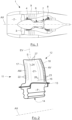
- Such a dawn which is marked by 11 on the Figure 2 , comprises a foot P by which it is fixed to a rotating body not shown, called a turbine disk, and a blade 12 carried by this foot P and constituting the aerodynamic part of this blade.
- the blade 11 comprises between the root P and the blade 12 an intermediate region 13 called platform.
- the assembly formed by the foot P and the blade 12 is a single, hollow, single-piece cast piece comprising internal ducts through which cooling air circulates. These internal ducts, not visible in the Figure 2 have intake vents opening on the lower face 14 of the foot P and through which these conduits are supplied with fresh air.
- the hollow wall of the blade 12 has through holes and slots through which the cooling air is evacuated.
- the blade 12 has a twisted left shape with a substantially rectangular outline, approaching a parallelepiped. It comprises a base 16 by which it is connected to the root P and which extends approximately parallel to the axis of rotation AX. It also comprises a leading edge 17 oriented radially relative to the axis AX and located at the upstream AM of the blade, that is to say the front region of this blade, relative to the direction of advancement of the engine which it equips in service. This blade also comprises a trailing edge 18 oriented approximately parallel to the leading edge 17 while being spaced from it along the axis AX to be located at the downstream region AV or rear of the blade. It also comprises a peak S approximately parallel to the base 16 and spaced from it in a radial direction relative to the axis AX.
- the two main walls of this dawn are its intrados wall 21, which is the wall visible in the Figure 2 , and its extrados wall which is the opposite wall spaced from the intrados wall, and which is not visible in the Figure 2 because it is masked by the intrados wall 21.
- the intrados and extrados walls are joined at the leading edge 17, at the trailing edge 18 and also in the region of the tip S of this blade. These walls are spaced from each other at the base 16 to allow the admission of cooling air into the internal region of the blade.
- the leading edge 17 has a curved shape and is provided with a series of cooling holes 22 passing through the wall of the blade in this region.
- the trailing edge 18 has a tapered shape and comprises a series of cooling slots 23. These slots 23 are short slots extending along the span direction and which are spaced apart from each other while being located in the extension of each other at a short distance from the trailing edge.
- Each slot 23 passes through the wall of the blade to take cooling air from inside this blade and blow it onto the intrados wall at the trailing edge.
- the trailing edge is provided with external ribs oriented parallel to the axis AX to channel the cooling air coming from these slots.
- the fluid in which this blade 11 is located moves relative to it from the leading edge 17 to the trailing edge 18 along the intrados 21 and the extrados.
- the intrados wall which is subjected to a significant heating in operation, comprises a series of holes 24 substantially parallel to the leading edge 17 while being located downstream of this leading edge, and another series of holes 26 substantially parallel to the trailing edge 18 while being located upstream of this trailing edge 18 and the slots 23 which it comprises.
- the series of holes 24 and 26 thus extend one and the other in the span direction EV of the blade, which is the radial direction relative to the axis AX.
- the region of the tip S of the blade 11 has, unlike the leading edge 17 and the trailing edge 18, a certain thickness, and it also has a shape delimiting a hollow portion called a bathtub.
- this summit S has a closing wall which connects the intrados and extrados walls, this closing wall having an orientation which is globally perpendicular to the intrados and extrados walls and parallel to the axis AX, which corresponds to an orientation perpendicular to the span direction EV.
- This closing wall which is not visible on the Figure 2 is located set back towards the axis AX relative to the free edge of the intrados wall and the free edge of the extrados wall, so that it constitutes, together with these edges, a hollow portion open in the direction opposite to the axis AX.
- a series of additional holes 27 passing through the intrados wall is provided along the apex S to ensure significant cooling of this blade apex which is subject to significant stresses due to the fact that it constitutes the part having the highest speed relative to the fluid.
- the series of holes 27 extends parallel to the closing wall, and the blade additionally includes holes not visible on the Figure 2 which pass through the closing wall to open into the hollow portion called the bathtub which is at the top of the blade.
- such a blade is a hollow one-piece part. It is manufactured by casting a metallic material, using a set of cores to delineate the internal ducts of its hollow portion as well as rod portions to form its through holes. The cores, rods and others are removed once that the molding operation is completed, typically with a chemical etching process capable of dissolving these elements without altering the molded material.
- the idea behind the invention is to improve the cooling of the blade in the region of the intrados wall which is in the vicinity of the trailing edge and the tip of the blade, since in practice this region is the first to deteriorate during the life of a blade.
- the air taken from the root thus travels directly, in a substantially straight line, to the upper cavity.
- the length of the path taken by this air, in the supply duct, for it to reach the upper cavity is thus less than or equal to the length of the blade in the span direction EV.
- this duct makes it possible to minimize the heating of the air supplied to the upper cavity.
- this supply duct is formed by a leading edge cooling ramp located upstream.
- this supply duct is constituted by a central duct of the blade, that is to say located approximately halfway between its leading edge and its trailing edge.
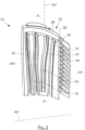
- the blade which is marked 31 in the Figure 3 where it is represented, thus comprises internal ducts arranged to bring into the region of the tip of the blade on the intrados side, the coolest possible cooling air so as to increase the cooling efficiency there.
- the interior of this blade 31 thus comprises in its upstream region, identified by AM, an upstream ramp 32 oriented according to its span direction EV and which runs along its leading edge.
- This upstream ramp 32 directly feeds an upper cavity 33 of the blade, while supplying fresh air to cooling holes passing through the wall portion forming the leading edge of the blade.
- This upstream ramp 32 extends from the root of the blade, identified by P, and by which it is directly supplied with air, to the top of the blade identified by S.
- the upper cavity 33 which is located near the top extends along the closing wall of this blade 31 and along its intrados wall, from the front to the rear of the blade which is identified by AV. These two walls are not visible in the Figure 3 since it is a representation of the hollow regions of this dawn.
- the upper cavity 33 reaches the trailing edge of the blade, in the downstream region AV, to supply fresh air to at least one cooling slot of this trailing edge, namely the slot closest to the tip which corresponds to one of the most severely stressed regions of the blade.
- This upper cavity 33 runs along the intrados wall, extending over a width less than the width or thickness of the blade, that is to say it has a width less than the distance separating the intrados and extrados walls. It is delimited laterally by a first face 34 which runs along the intrados and a second face 36 spaced from the first. The first face 34 and the second face 36 are joined at the front and rear of this upper cavity.
- the upper cavity 33 is delimited vertically by a bottom 37 parallel to the closing wall and spaced from it and by an upper face 38 which is the lower face of the closing wall.
- the intrados wall may comprise through holes, not shown, allowing the upper cavity 33 to additionally cool the external face of the intrados wall in this region.
- the interior of the blade 31 also includes a downstream ramp 41 extending along the trailing edge from the root P to the region of the apex S to end under the rear part of the upper cavity 33.
- This downstream ramp 41 feeds a series of trailing edge cooling slots, not visible in the Figure 3 .
- the majority of the cooling slots of the trailing edge are thus supplied with air by the downstream ramp 41, but it is the upper cavity which supplies the slot(s) closest to the apex S, which is a region subject to greater thermal stresses.
- the slots close to the apex are thus supplied with cooler air and/or having a greater flow rate than the others.
- the dawn of the Figure 3 further comprises a first central duct 42, a second central duct 43 and a downstream duct 44, oriented in the span direction, and communicating with each other in a so-called trombone arrangement.
- the first central duct 42 which runs along the upstream ramp 32 collects air at the level of the foot of the blade, and it communicates at the level of the tip S with the second central duct 43 to supply it with air.
- This second central duct 43 is connected at the base of the blade with the downstream duct 44 to supply it with air.
- This downstream duct 44 extends in a straight line from the root P to the top S, parallel to the downstream ramp 41 which it runs along while being located upstream of this downstream ramp 41.
- the end of the downstream duct 44 ends in the region of the apex S by running along the second face 36 of the upper cavity 33 to bypass it.
- the intrados wall can be provided with through holes allowing the ducts 42, 43, 44 to supply cooling air to the external face of this wall to cool it by forming an external film there.
- the intrados wall may comprise, at the level of the downstream duct 44, through holes through which this downstream duct 44 supplies air cooling the external face of the intrados wall upstream of the trailing edge of the blade.
- the downstream duct 44 can supply the downstream ramp 41 through a series of calibrated passages (not shown), regularly spaced from each other along the span direction EV. In this case, instead of being supplied by the second duct 43, the downstream duct 44 then directly collects cooling air at the level of the blade root, so that the air it supplies to the downstream ramp is as cool as possible.
- downstream ramp 41 can be supplied in a calibrated manner by the downstream conduit 44, or, on the contrary, it can be supplied directly in the region of the foot of the blade.
- passages are then calibrated to approximately achieve a desired airflow rate in each trailing edge cooling slot.
- the desired airflow rate for a given slot is conditioned by the trailing edge thermal constraints in the region cooled by that slot.
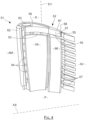
- the blade which is identified by 51 comprises an upper cavity 52 which is supplied directly by a central conduit 53 entirely dedicated to this upper cavity 52.
- the supply duct of the upper cavity does not participate in the cooling of the leading edge.
- a first lateral cavity 54 is also provided along the intrados wall, and a second lateral cavity 56 along the extrados. These two lateral cavities thermally insulate the central duct as well as an upstream duct for calibrated supply of a cooling ramp for the leading edge of the blade, the intrados and extrados walls which are heated by the gas flows surrounding the blade.
- the upper cavity 52 of this blade 51 has a shape substantially identical to that of the blade 31 of the Figure 3 . It is located near the S apex, extends along the closing and intrados walls, from the front to the rear of the blade. Here too, the entire part of the S apex located on the intrados side is supplied with air through this upper cavity 52, over substantially its entire length up to the rear end. This upper cavity 52 also extends to the trailing edge, to supply fresh air to at least the slot closest to the apex S, marked by 55, and possibly some adjacent slots.
- this upper cavity 52 is also less than the thickness of the blade. It is delimited laterally by a first face 57 which runs along the intrados and a second face 58 spaced from the first face, these faces being joined at the front and at the rear. In the vertical direction, the upper cavity 52 is delimited by a bottom 59 parallel to the closing wall, and by the lower face 61 of this closing wall.
- the intrados wall may also have through holes to cool the outer face of the intrados wall in the tip region.
- the central duct 53 feeds this upper cavity 52 by extending from the root P of the blade through which it is supplied with air, to the top of this blade, where it opens entirely into the bottom 59 of this upper cavity 52.
- the leading edge of the blade 51 is cooled by an upstream ramp 62 which extends from the base of the blade to the tip S, but which is supplied not directly by the root, but by an upstream duct 63 in a calibrated manner.
- This calibrated supply is ensured by calibrated passages 64 regularly spaced along the span direction EV of the blade and which each connect the upstream duct 63 to the upstream ramp 62.
- Each passage 64 has a calibrated diameter, that is to say chosen at the design stage to obtain in the area of the ramp 62 that it supplies a desired air flow which is conditioned by the thermal of the blade in this region.
- the first lateral cavity 54 has a small thickness, and it extends from the foot P to the region of the summit S while having a generally rectangular outline.
- This first lateral cavity 54 is ends under the upper cavity 52 so as not to cover it. It has a width sufficient to hide or cover the central conduit 53 as well as the upstream conduit 63 which runs alongside this central conduit.
- the second lateral cavity 56 also has a small thickness, and it extends from the foot P to the region of the apex S but covering the upper cavity 52.
- This second lateral cavity has a generally rectangular outline, having a sufficient width to mask or cover the central duct as well as the upstream duct 63 and the upper cavity 52 on the extrados side.
- the air which is supplied to the upper cavity 52 by the central duct 53 is kept cool during its travel in this duct, thanks to the thermal screens which the lateral cavities 54 and 56 form.
- the air which is supplied by the upstream duct 63 is also kept cool during its travel in this upstream duct.
- trailing edge cooling slot(s) located in the region of the apex S are supplied with air by the upper cavity 52.
- the other trailing edge slots, marked 67, are supplied by a downstream ramp 66 which extends from the foot P, where it is supplied directly via this foot, to the region of the apex S to terminate under the rear part of the upper cavity 52.
- the slots 67 are thus supplied with air by the downstream ramp 66, but it is the upper cavity 52 which supplies the slot(s) closest to the top S with cooler air and/or having a higher flow rate.
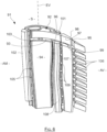
- the blade which is identified by 71 also comprises an upper cavity 72 supplied by a dedicated central duct 73 which is thermally insulated by two lateral cavities 74 and 76. These two lateral cavities also isolate an upstream duct of calibrated supply of a cooling ramp of the leading edge of the blade. But in this third embodiment, the two lateral cavities 74 and 76 are joined in the rear or downstream part of the blade to envelop this central duct 73 on three quarters of its circumference, so as to provide better thermal insulation for this conduit 73.
- the upper cavity 72 has a shape substantially identical to that of the blades of the figures 3 And 4 . It is located near the apex S, extends along the closing and intrados walls, from the front to the rear of the blade. The entire part of the apex S located on the intrados side is supplied by this upper cavity 72, over its entire length up to the rear end. This upper cavity 72 also extends to the trailing edge, to supply at least the slot closest to the apex S, marked by 75, and possibly some adjacent slots.
- this upper cavity 72 is also less than the thickness of the blade. It is delimited laterally by a first face 77 which runs along the intrados and a second face 78 spaced from the first, these faces being joined at the front and at the rear. In the vertical direction, the upper cavity 72 is delimited by a bottom 79 parallel to the closing wall, and by the lower face 81 of this closing wall. In the region of the tip S of the blade, the intrados wall may also have through holes for cooling the external face of the intrados wall in the tip region.
- the central duct 73 feeds this upper cavity 72 by extending from the foot of the blade through which it is supplied with air, to the top S, where it opens entirely into the bottom 79 of the upper cavity.
- the leading edge of the blade 71 is cooled by an upstream ramp 82 which extends from the base of the blade to the tip S, and which is supplied by an upstream duct 83 in a calibrated manner by means of calibrated passages regularly spaced along the span direction EV of the blade and which each connect the upstream duct to the upstream ramp.
- the wall of the blade has holes in the region of the leading edge, not shown, through which the air from the ramp passes through the wall to cool the external face of the leading edge.
- the first lateral cavity 74 has a small thickness and extends from the foot to the region of the apex S with a generally rectangular outline. It ends below the upper cavity 72 without covering it. It has a width sufficient to mask or cover the central conduit 73 as well as the upstream conduit 83 which runs alongside this central conduit.
- the second lateral cavity 76 also has a small thickness, and it extends from the foot to the region of the apex S but covering the upper cavity 72. It has a generally rectangular outline, having a sufficient width to mask or cover the central conduit 73 and the upstream conduit 83 and the upper cavity 72 on the extrados side.
- the two lateral cavities 74 and 76 are here joined together in the rear or downstream part instead of being separate. In this way, these two lateral cavities surround the central duct 73 over three-quarters of its circumference so as to further improve its thermal insulation from the external environment, so that it can provide the upper cavity 72 which it feeds with even cooler air.
- these two cavities are joined by a junction zone located downstream from the central duct, and which extends over the majority of the height of this central duct.
- These two cavities with their junction zone thus constitute a single cavity enveloping the central duct over the majority of its external surface.
- the height or length of the junction zone along the span direction EV corresponds to the height or length of the first lateral cavity along the span direction EV.
- the supply of these two lateral cavities can be carried out separately by two supply ducts taking the air separately from the blade root, the lateral cavities then being united only in the region of the blade. It may also be possible to provide a single supply channel for the two lateral cavities having a cross-sectional shape corresponding to that of the letter U.
- the trailing edge cooling slot(s) located in the region of the apex S are supplied with air by the upper cavity 72.
- the other trailing edge slots, marked by 86, are supplied by a downstream ramp 87 which extends from the root, where it is supplied directly via this root, to the region of the apex S to terminate under the rear part of the upper cavity 72.
- the blade which is identified by 91 also comprises an upper cavity 92 supplied by a central duct 93 isolated by two lateral cavities 94 and 96. But in this fourth embodiment, the trailing edge is cooled by a downstream ramp which is supplied in a calibrated manner by a downstream duct.
- the upper cavity 92 has a shape substantially identical to that of the blades of the figures 3 to 5 . It is located near the apex S, extends along the closing and intrados walls, from the front to the rear of the blade. The entire part of the apex S located on the intrados side is supplied with cooling air by this upper cavity 92, over its entire length up to the rear end. This upper cavity 92 also extends to the trailing edge, to supply at least the slot closest to the apex S, marked by 95, and possibly some adjacent slots.
- This upper cavity 92 is delimited laterally by a first face 97 which runs along the intrados and a second face 98 spaced from the first, these faces being joined at the front and at the rear. It is delimited vertically by a bottom 99 parallel to the closing wall, and by the lower face 101 of this closing wall.
- the intrados wall may also have through holes for cooling the external face of the intrados wall in the apex region.
- the central duct 93 feeds this upper cavity 92 by extending from the foot of the blade by which it is supplied with air, to the apex S, where it opens entirely into the bottom 99.
- the leading edge of the blade 91 is cooled by an upstream ramp 102 which extends from the base of the blade to the tip S, being supplied by an upstream duct 103 in a calibrated manner by means of calibrated passages 105 regularly spaced along the span direction EV of the blade and which each connect the upstream duct 103 to the upstream ramp 102.
- the wall of the blade comprises, in the region of the leading edge, through holes through which the air from the ramp cools the external face of the leading edge.
- the second lateral cavity 96 also has a small thickness, and it extends from the foot to the region of the apex S but covering the upper cavity 92. It has a generally rectangular outline, of sufficient width to mask or cover the central conduit 93 and the upstream conduit 103 and the upper cavity 92 on the extrados side.
- the trailing edge cooling slot(s) located in the region of the apex S are supplied with air by the upper cavity 92.
- the other trailing edge slots, identified by 106, are supplied by a downstream ramp 107 which extends from the foot to the region of the apex S.
- This downstream ramp 107 is here supplied in a calibrated manner by a downstream duct 108 which extends from the foot of the blade to the region of its apex S where it bypasses a rear part of the upper cavity 92.
- This downstream duct 108 is located between the central duct 93 and the downstream ramp 107, and it is not masked by either the lateral cavity 94 or the lateral cavity 96.
- the downstream duct 108 supplies the downstream ramp 107 in a calibrated manner, by means of a series of calibrated passages 109 regularly spaced from one another along the span direction EV and each joining the downstream duct to the ramp 107.
- the blade which is identified by 111 also comprises an upper cavity 112 supplied by a central duct 113 isolated by two lateral cavities 114 and 116.
- the trailing edge is also cooled by a downstream ramp supplied in a calibrated manner by a downstream duct, but this downstream duct is thermally protected by lateral cavities of the blade so as to provide cooler air for cooling the trailing edge.
- the upper cavity 112 has a shape substantially identical to that of the blades of the figures 3 to 6 . It is located near the S apex, extends along the closing and intrados walls, from the front to the rear of the blade. The entire part of the S apex located on the intrados side is supplied with cooling air by this upper cavity 112, over its entire length up to the rear end. This upper cavity 112 also extends to the trailing edge, to supply at least the slot closest to the apex S, marked by 115, and possibly some adjacent slots.
- This upper cavity 112 is delimited laterally by a first face 117 which runs along the intrados and a second face 118 spaced from the first, these faces being joined at the front and at the rear. It is delimited vertically by a bottom 119 parallel to the closing wall, and by the lower face 121 of this closing wall.
- the central duct 113 feeds this upper cavity 112 by extending from the foot of the blade by which it is supplied with air, to the top S, where it opens entirely into the bottom 119.
- the leading edge of the blade 111 is cooled by an upstream ramp 122 which extends from the base of the blade to the tip S, supplied by an upstream duct 123 in a calibrated manner thanks to calibrated passages 124 regularly spaced along the span direction EV of the blade and which each connect the upstream duct 123 to the upstream ramp 122.
- the wall of the blade has through holes in the leading edge region through which the air from the ramp cools the outer face of the leading edge.
- the first lateral cavity 114 has a small thickness and extends from the root to the top region S, having a generally rectangular outline. It ends under the upper cavity 112 without covering it, and it has a width sufficient to mask or cover the central duct 113 as well as the upstream duct 123 which runs along this central duct 113, and the downstream duct for calibrated supply of the downstream ramp.
- the second lateral cavity 116 also has a small thickness, and it extends from the foot to the region of the apex S but covering the upper cavity 112. It has a generally rectangular outline, of sufficient width to mask or cover the central conduit 113, the upstream conduit 123 and the upper cavity 112 on the extrados side, as well as the downstream conduit for calibrated supply of the downstream ramp.
- the cooling slot 115 of the trailing edge located in the region of the apex S is supplied with air by the upper cavity 112.
- the other slots of the trailing edge, identified by 126, are supplied by the downstream ramp 127 which extends from the foot to the region of the apex S.
- This downstream ramp 127 is here supplied in a calibrated manner by the downstream duct 128 which extends from the foot of the blade to the region of its tip to end at the level of the tip S, bypassing the upper cavity 112.
- This downstream duct 128 is located between the central duct 113 and the downstream ramp 127.
- the downstream duct 128 supplies the downstream ramp 127 in a calibrated manner, by means of a series of calibrated passages 129 regularly spaced from one another and each joining the downstream duct 128 to the ramp 127.
- the lateral cavities 114 and 116 are here arranged to cover the upstream conduit 123, the central conduit 113 as well as the downstream conduit 128 so as to jointly cover these three elements to thermally insulate them from the intrados wall and the extrados wall.
- the blade which is identified by 131 also comprises an upper cavity 132 supplied by a central duct 133, but this is isolated by a single lateral cavity 134 located on the intrados side. This makes it possible to simplify the manufacture of the blade while providing satisfactory cooling efficiency due to the fact that in practice, the intrados wall tends to heat up significantly more than the extrados wall.
- the upper cavity 132 has a shape substantially identical to that of the blades of the figures 3 to 7 . It is located near the apex S, extends along the closing and intrados walls, from the front to the rear of the blade. The entire part of the apex S located on the intrados side is supplied with cooling air by this upper cavity 132, over its entire length up to the rear end. This upper cavity 132 also extends to the trailing edge, to supply at least the slot closest to the apex S, marked by 135, and possibly some adjacent slots.
- This upper cavity 132 is delimited laterally by a first face 137 which runs along the intrados and a second face 138 spaced from the first, these faces being joined at the front and at the rear. It is delimited vertically by a bottom 139 parallel to the closing wall, and by the lower face 141 of this closing wall.
- the central duct 133 feeds this upper cavity 132 by extending from the foot of the blade by which it is supplied with air, to the top S, where it opens entirely into the bottom 139.
- the leading edge of the blade 131 is cooled by an upstream ramp 142 which extends from the base of the blade to the tip S, which is supplied by an upstream duct 143 in a calibrated manner by means of calibrated passages 144 which are regularly spaced along the span direction EV of the blade and which each connect the upstream duct 143 to the upstream ramp 142.
- the wall of the blade has through holes in the region of the leading edge by means of which the air from the ramp cools the external face of the leading edge.
- the lateral cavity 134 has a small thickness and extends from the foot to the region of the apex S, having a generally rectangular outline. It ends under the upper cavity 132 without covering it. It has a width sufficient to mask or cover the central conduit 133 as well as the upstream conduit 143 which runs alongside this central conduit 133.
- the cooling slot 135 of the trailing edge located in the region of the apex S is supplied with air by the upper cavity 132.
- the other slots of the trailing edge, identified by 146, are supplied by a downstream ramp 147 which extends from the foot to the region of the apex S.
- This downstream ramp 147 is here supplied in a calibrated manner by a downstream conduit 148 which extends from the foot of the blade to the region of its tip to end at the level of the tip S, bypassing the upper cavity 132.
- This downstream conduit 148 is located between the central conduit 133 and the downstream ramp 147.
- the downstream conduit 148 supplies the downstream ramp 147 in a calibrated manner, by means of a series of calibrated passages 149 regularly spaced from each other along the span direction EV and each joining this downstream conduit 148 to the ramp 147.
- the lateral cavity 134 covers the upstream duct 143 as well as the central duct 133 and the downstream duct 148 so as to thermally insulate these three elements from the intrados wall to reduce the heating of the air which they carry.
- the apex region is supplied with air by the upper cavity with respect to the entire portion of the apex extending along the intrados.
- the other portions of the apex are supplied with air by the other ducts, ramps or cavities of the blade, such as in particular the upstream ramp and possibly the upstream duct, the downstream ramp and possibly the downstream duct, and where appropriate the second lateral cavity running along the extrados.
- the upper cavity has a thickness less than the thickness of the blade, i.e. the distance separating the intrados from the extrados.
- the thickness of this cavity can be reduced to less than half the thickness of the blade.
- the upper cavity makes it possible to significantly improve the cooling of the blade tip region, in particular by supplying very cool air to the trailing edge slot which is closest to the tip.
- This upper cavity also ensures cooling by thermal conduction of the blade walls which delimit it, such as for example the closing wall of the blade.
- holes passing through the walls of the blade and opening into the internal lateral cavities forming a heat shield may be provided to establish optimal air circulation in these cavities.
- Each of these holes is advantageously located at a depression zone to promote air circulation.
- Each of these holes ensures that the air collected at the base of the blade and which is conveyed into a cavity forming a heat shield, is sucked out of the blade, after having passed through this cavity.
- the cooling of the blade is further optimized by minimizing the pressure losses in each internal duct. to reduce heat exchanges, and on the contrary by providing turbulence promoters in each lateral cavity to increase heat exchanges.
- the side cavities thus have increased efficiency as a thermal screen because they absorb the heat from the external walls they run alongside, and the air circulating in the internal ducts is subject to few pressure losses in order to circulate quickly and heat up as little as possible.
- Internal ducts such as the upstream duct, the central duct and the downstream duct thus have smooth internal walls to promote rapid circulation of the cooling air by minimizing heat exchange between this air and the walls of the duct in which it travels.
- Each lateral cavity is advantageously provided with deflectors which promote air circulation in all regions of the cavity.
- the internal faces of the cavity are provided with disruptors and/or bridges to create turbulence in the circulation of the air in order to promote a high level of heat exchange between the air and the walls it passes along.
- the described blade can be made by direct manufacturing, by additive manufacturing, or by casting.
Landscapes
- Engineering & Computer Science (AREA)
- Mechanical Engineering (AREA)
- General Engineering & Computer Science (AREA)
- Turbine Rotor Nozzle Sealing (AREA)
Description
- L'invention concerne une aube de turbine de moteur d'aéronef de type turbomachine, telle qu'un turboréacteur ou un turbopropulseur.
- Dans un tel moteur, l'air extérieur est admis dans une manche d'entrée pour traverser une soufflante comportant une série de pales rotatives avant de se scinder en un flux primaire central et un flux secondaire entourant le flux primaire.
- Le flux primaire est ensuite compressé avant d'arriver dans une chambre de combustion, après quoi il se détend en traversant un ensemble de turbines avant d'être évacué vers l'arrière en générant de la poussée. Le flux secondaire est quant à lui propulsé directement vers l'arrière par la soufflante pour générer une poussée complémentaire.
- La détente dans les turbines, qui permet d'entraîner le compresseur et la soufflante, a lieu à température élevée du fait qu'elle se produit immédiatement après la combustion. Cette turbine est ainsi conçue et dimensionnée pour fonctionner dans des conditions sévères de température, de pression et de débit de fluide.
- Chaque turbine comporte une succession d'étages comportant chacun une série d'aubes orientées radialement et régulièrement espacées autour d'un arbre de rotation du moteur. Cet arbre central porte les éléments rotatifs de la turbine ainsi que les éléments rotatifs du compresseur et de la soufflante.
- Concrètement, les aubes de la turbine qui sont soumises aux conditions les plus sévères sont celles des premiers étages de détente de cette turbine, à savoir les étages les plus proches de la zone de combustion et qui sont communément appelés étages haute pression.
- D'une manière générale, les besoins accrus en performances et l'évolution des réglementations conduisent à concevoir des moteurs de plus faible taille fonctionnant dans des environnements de plus en plus sévères. Ceci implique d'accroître la tenue et la performance des aubes de turbine haute pression en particulier en ce qui concerne leur tenue en température.
- Néanmoins, les améliorations existantes en ce qui concerne les matériaux et les revêtements de ces aubes ne suffisent pas pour leur permettre de supporter les températures élevées pouvant être atteintes par le flux en aval de la chambre de combustion. Cette situation conduit à reconsidérer le refroidissement de ces aubes pour l'améliorer afin qu'elles puissent supporter ces nouvelles conditions de fonctionnement.
- Ce refroidissement est assuré en faisant circuler à l'intérieur de ces aubes de l'air frais qui est prélevé dans le turboréacteur en amont de la combustion. Cet air est admis en pied d'aube, pour cheminer le long d'un circuit interne de l'aube afin de la refroidir, et il est évacué hors de l'aube par des perçages traversant la paroi de cette aube et répartis sur cette paroi. Ces perçages servent à évacuer l'air de refroidissement, mais ils créent aussi à la surface externe de l'aube un film d'air plus froid que l'air issu de la combustion, ce qui contribue aussi à limiter la température de l'aube.
- Pour accroître l'efficacité de refroidissement, les régions intérieures de l'aube dans lesquelles circule l'air de refroidissement comportent des artifices, c'est-à-dire des reliefs internes qui perturbent l'écoulement fluide de l'air de refroidissement pour accroître le transfert thermique depuis la paroi de l'aube vers cet air de refroidissement circulant dans les conduits internes de l'aube.
- Ces architectures de refroidissement traditionnelles sont pénalisées par le fait que la longueur du circuit interne de l'aube donne lieu à un air trop fortement réchauffé lorsqu'il atteint la fin de ce circuit, de sorte que son efficacité de refroidissement est limitée dans les régions de fin de parcours, et en particulier au niveau du sommet d'aube où l'on cherche au contraire à obtenir une efficacité de refroidissement accrue.
- En pratique dans les aubes connues, notamment des documents
EP2119873A2 ,EP1065343A2 ,WO03042503A1 EP1895098B1 ,US2008080979A1 etEP1882819B1 , l'efficacité de refroidissement s'avère inadéquate. - Le but de l'invention est de proposer une structure d'aube permettant d'améliorer l'efficacité de refroidissement de cette aube.
- A cet effet, l'invention a pour objet une aube de turbine de turbomachine et des moyens de moulage pour fabriquer une telle aube, comme défini dans les revendications.
-
- La
figure 1 est une vue schématique d'un turboréacteur à double flux en coupe longitudinale ; - La
figure 2 est une vue en perspective d'une aube de turbine de turboréacteur montré sur lafigure 1 ; - La
figure 3 est une vue en perspective représentant les parties internes creuses d'une aube de turbine selon un premier mode de réalisation de l'invention non couvert par les revendications ; - La
figure 4 est une vue en perspective représentant les parties internes creuses d'une aube de turbine selon un deuxième mode de réalisation de l'invention ; - La
figure 5 est une vue en perspective représentant les parties internes creuses d'une aube de turbine selon un troisième mode de réalisation de l'invention ; - La
figure 6 est une vue en perspective représentant les parties internes creuses d'une aube de turbine selon un quatrième mode de réalisation de l'invention ; - La
figure 7 est une vue en perspective représentant les parties internes creuses d'une aube de turbine selon un cinquième mode de réalisation de l'invention ; - La
figure 8 est une vue en perspective représentant les parties internes creuses d'une aube de turbine selon un sixième mode de réalisation de l'invention non couvert par les revendications ; - Comme visible sur la
figure 1 , une partie avant d'un turboréacteur à double flux 1 comporte une manche d'entrée 2 dans laquelle est admis l'air avant d'être aspiré par les pales d'une soufflante 3. Après avoir passé la région de la soufflante, l'air se divise en un flux primaire central et un flux secondaire qui entoure le flux primaire. - Le flux d'air primaire traverse ensuite un premier compresseur 4 situé immédiatement après la soufflante 3 alors que le flux secondaire est propulsé vers l'arrière pour directement générer une poussée additionnelle en étant soufflé autour du flux primaire.
- Le flux primaire traverse ensuite un second étage de compression 6, avant d'atteindre une chambre 7 où a lieu sa combustion, après injection et vaporisation d'un carburant. Après combustion, ce flux primaire se détend dans une turbine haute pression 8 puis dans une turbine basse pression non représentée pour entrainer en rotation les étages de compression et la soufflante, avant d'être expulsé vers l'arrière du moteur pour générer une poussée.
- Le moteur 1 et ses composants ont une forme de révolution autour d'un axe longitudinal AX. Il comporte notamment un carter externe 9 ayant lui aussi une forme de révolution et s'étendant depuis l'avant du moteur où il délimite la manche d'entrée d'air, jusqu'à la partie arrière où il délimite le conduit par lequel les flux primaire et secondaire sont évacués, l'avant et l'arrière à considérer par rapport à la direction d'avancement de l'aéronef équipé de ce turboréacteur. Ce carter 9 supporte les composants rotatifs situés au centre du moteur et qui comprennent un arbre rotatif portant les pales de la soufflante ainsi que les étages de compression et la turbine avec leurs aubes.
- Une telle aube, qui est repérée par 11 sur la
figure 2 , comprend un pied P par lequel elle est fixée à un corps rotatif non représenté, appelé disque de turbine, et une pale 12 portée par ce pied P et constituant la partie aérodynamique de cette aube. Comme visible sur lafigure 2 , l'aube 11 comporte entre le pied P et la pale 12 une région intermédiaire 13 appelée plateforme. - L'ensemble que forme le pied P et la pale 12 est une pièce unique monobloc creuse issue de fonderie et comportant des conduits internes par lesquels circule de l'air de refroidissement. Ces conduits internes non visibles dans la
figure 2 comportent des bouches d'admission s'ouvrant en face inférieure 14 du pied P et par lesquelles ces conduits sont alimentés en air frais. La paroi creuse de la pale 12 comporte des trous traversants et des fentes par lesquels est évacué l'air de refroidissement. - La pale 12 a une forme gauche vrillée ayant un contour sensiblement rectangulaire, se rapprochant d'un parallélépipède. Elle comprend une base 16 par laquelle elle est raccordée au pied P et qui s'étend à peu près parallèlement à l'axe de rotation AX. Elle comprend aussi un bord d'attaque 17 orienté radialement par rapport à l'axe AX et situé au niveau de l'amont AM de l'aube, c'est-à-dire la région avant de cette aube, par rapport à la direction d'avancement du moteur qu'elle équipe en service. Cette aube comporte aussi, un bord de fuite 18 orienté à peu près parallèlement au bord d'attaque 17 en étant espacé de celui-ci le long de l'axe AX pour être situé au niveau de la région aval AV ou arrière de l'aube. Elle comprend encore un sommet S à peu près parallèle à la base 16 et espacé de celle-ci selon une direction radiale par rapport à l'axe AX.
- Les deux parois principales de cette aube sont sa paroi d'intrados 21, qui est la paroi visible dans la
figure 2 , et sa paroi d'extrados qui est la paroi opposée espacée de la paroi d'intrados, et qui n'est pas visible dans lafigure 2 du fait qu'elle est masquée par la paroi d'intrados 21. Les parois d'intrados et d'extrados sont réunies au niveau du bord d'attaque 17, au niveau du bord de fuite 18 et également dans la région du sommet S de cette aube. Ces parois sont espacées l'une de l'autre au niveau de la base 16 pour permettre l'admission d'air de refroidissement dans la région interne de la pale. - Le bord d'attaque 17 a une forme bombée et il est pourvu d'une série de trous de refroidissements 22 traversant la paroi de l'aube dans cette région. Le bord de fuite 18 a quant à lui une forme effilée, et il comporte une série de fentes de refroidissement 23. Ces fentes 23 sont des fentes de faibles longueurs s'étendant le long de la direction d'envergure et qui sont espacées les unes des autres en étant situées dans le prolongement les unes des autres à faible distance du bord de fuite.
- Chaque fente 23 traverse la paroi de l'aube pour prélever de l'air de refroidissement à l'intérieur de cette aube et le souffler sur la paroi d'intrados au niveau du bord de fuite. Complémentairement, le bord de fuite est pourvu de nervures externes orientées parallèlement à l'axe AX pour canaliser l'air de refroidissement issu de ces fentes.
- En fonctionnement, le fluide dans lequel est située cette aube 11 se déplace par rapport à celle-ci depuis le bord d'attaque 17 vers le bord de fuite 18 en longeant l'intrados 21 et l'extrados. La paroi d'intrados qui est soumise à un échauffement significatif en fonctionnement, comporte une séries de trous 24 sensiblement parallèlement au bord d'attaque 17 en étant situés en aval de ce bord d'attaque, et une autre série de trous 26 sensiblement parallèlement au bord de fuite 18 en étant situés en amont de ce bord de fuite 18 et des fentes 23 qu'il comporte . Les séries de trous 24 et 26 s'étendent ainsi l'une et l'autre selon la direction d'envergure EV de la pale, qui est la direction radiale par rapport à l'axe AX.
- La région du sommet S de l'aube 11 présente, contrairement au bord d'attaque 17 et au bord de fuite 18, une certaine épaisseur, et il a par ailleurs une forme délimitant une portion creuse dite en baignoire.
- Plus concrètement, ce sommet S présente une paroi de fermeture qui raccorde les parois d'intrados et d'extrados, cette paroi de fermeture ayant une orientation qui est globalement perpendiculaire aux parois d'intrados et d'extrados et parallèle à l'axe AX, ce qui correspond à une orientation perpendiculaire à la direction d'envergure EV. Cette paroi de fermeture qui n'est pas visible sur la
figure 2 est située en retrait vers l'axe AX par rapport au bord libre de la paroi d'intrados et au bord libre de la paroi d'extrados, de sorte qu'elle constitue, conjointement avec ces bords une portion creuse ouverte en direction opposée à l'axe AX. - Une série de trous supplémentaires 27 traversant la paroi d'intrados est prévue le long du sommet S pour assurer un refroidissement significatif de ce sommet de pale qui subit des contraintes importantes du fait qu'il constitue la partie ayant la vitesse la plus élevée par rapport au fluide.
- La série de trous 27 s'étend parallèlement à la paroi de fermeture, et la pale comporte, complémentairement, des trous non visibles sur la
figure 2 qui traversent la paroi de fermeture pour déboucher dans la portion creuse appelée baignoire qui est au sommet de la pale. - Comme indiqué plus haut, une telle aube est une pièce monobloc creuse. Elle est fabriquée par moulage d'un matériau métallique, en utilisant un ensemble de noyaux pour délimiter les conduits internes de sa portion creuse ainsi que des portions de tiges pour former ses trous traversants. Les noyaux, tiges et autres sont retirés une fois que l'opération de moulage est terminée, typiquement avec un processus d'attaque chimique à même de dissoudre ces éléments sans altérer le matériau moulé.
- Les figures qui suivent montrent des régions internes de l'aube selon l'invention qui y sont représentées par les formes des noyaux permettant de fabriquer cette aube. Autrement dit, les formes qui sont en relief sur les figures qui suivent constituent des représentations des formes creuses de l'aube selon l'invention.
- L'idée à la base de l'invention est d'améliorer le refroidissement de l'aube dans la région de la paroi d'intrados qui est au voisinage du bord de fuite et du sommet de l'aube, attendu qu'en pratique cette région est la première à se détériorer au cours de la vie d'une aube.
- Ceci est obtenu en prévoyant dans la région du sommet de l'aube une cavité supérieure s'étendant de l'avant à l'arrière de l'aube et qui est alimentée directement en air provenant du pied de l'aube par un conduit d'alimentation de cette cavité supérieure.
- L'air prélevé dans le pied chemine ainsi sans détour, de manière sensiblement rectiligne, jusqu'à la cavité supérieure. La longueur du parcours de cet air, dans le conduit d'alimentation, pour qu'il atteigne la cavité supérieure est ainsi inférieure ou égale à la longueur de la pale selon la direction d'envergure EV. Autrement dit, en réalisant une alimentation directe, ce conduit permet de minimiser l'échauffement de l'air apporté à la cavité supérieure.
- Dans le premier mode de réalisation, non couvert par les revendications, correspondant à la
figure 3 , ce conduit d'alimentation est formé par une rampe de refroidissement du bord d'attaque située en amont. Dans les autres modes de réalisation, correspondant auxfigures 4 à 8 , ce conduit d'alimentation est constitué par un conduit central de l'aube, c'est-à-dire situé sensiblement à mi-distance entre son bord d'attaque et son bord de fuite. - Dans le premier mode de réalisation de l'invention, l'aube, qui est repérée par 31 dans la
figure 3 où elle est représentée, comprend ainsi des conduits internes agencés pour apporter dans la région du sommet de l'aube du côté intrados, de l'air de refroidissement le plus frais possible de manière à y accroître l'efficacité du refroidissement. - L'intérieur de cette aube 31 comporte ainsi dans sa région amont, repérée par AM, une rampe amont 32 orientée selon sa direction d'envergure EV et qui longe son bord d'attaque. Cette rampe amont 32 alimente directement une cavité supérieure 33 de l'aube, tout en approvisionnant en air frais des trous de refroidissement traversant la portion de paroi formant le bord d'attaque de l'aube. Cette rampe amont 32 s'étend depuis le pied de l'aube, repéré par P, et par lequel elle est alimentée en air de façon directe, jusqu'au sommet de l'aube repéré par S.
- La cavité supérieure 33 qui est située à proximité du sommet s'étend le long de la paroi de fermeture de cette aube 31 et le long de sa paroi d'intrados, depuis l'avant jusqu'à l'arrière de l'aube qui est repéré par AV. Ces deux parois ne sont pas visibles dans la
figure 3 puisqu'il s'agit d'une représentation des régions creuses de cette aube. - Toute la partie du sommet S de l'aube 31 qui est située du côté de son intrados, sur sensiblement toute sa longueur et en particulier jusqu'à l'extrémité aval de ce sommet S est ainsi approvisionné en air par la cavité supérieure 33 qui est elle-même alimentée par la rampe amont 32 formant conduit.
- La cavité supérieure 33 atteint le bord de fuite de l'aube, en région aval AV, pour alimenter en air frais au moins une fente de refroidissement de ce bord de fuite, à savoir la fente la plus proche du sommet qui correspond à l'une des régions les plus sévèrement sollicitées de l'aube.
- Cette cavité supérieure 33 longe la paroi d'intrados en s'étendant sur une largeur inférieure à la largeur ou épaisseur de la pale, c'est-à-dire qu'elle a une largeur inférieure à la distance séparant les parois d'intrados et d'extrados. Elle est délimitée latéralement par une première face 34 qui longe l'intrados et une seconde face 36 espacée de la première. La première face 34 et la deuxième face 36 sont réunies à l'avant et à l'arrière de cette cavité supérieure.
- La cavité supérieure 33 est délimitée verticalement par un fond 37 parallèle à la paroi de fermeture et espacé de celle-ci et, par une face supérieure 38 qui est la face inférieure de la paroi de fermeture.
- Dans la région du sommet S de la pale, la paroi d'intrados peut comporter des trous traversants, non représentés, permettant à la cavité supérieure 33 de refroidir en outre la face externe de la paroi d'intrados dans cette région.
- L'intérieur de l'aube 31 comporte encore une rampe aval 41 s'étendant le long du bord de fuite depuis le pied P jusqu'à la région du sommet S pour se terminer sous la partie arrière de la cavité supérieure 33. Cette rampe aval 41 alimente une série de fentes de refroidissement du bord de fuite, non visibles dans la
figure 3 . - La majorité des fentes de refroidissement du bord de fuite sont ainsi alimentées en air par la rampe aval 41, mais c'est la cavité supérieure qui alimente la ou les fentes les plus proches du sommet S, qui est une région soumise à des contraintes thermiques plus importantes. Les fentes proches du sommet sont ainsi alimentées avec un air plus frais et/ou ayant un débit plus important que les autres.
- L'aube de la
figure 3 comporte encore un premier conduit central 42, un second conduit central 43 et un conduit aval 44, orientés selon la direction d'envergure, et communiquant les uns avec les autres selon un agencement dit en trombone. Le premier conduit central 42 qui longe la rampe amont 32 collecte de l'air au niveau du pied de l'aube, et il communique au niveau du sommet S avec le second conduit central 43 pour l'alimenter en air. - Ce second conduit central 43 est relié au niveau de la base de l'aube avec le conduit aval 44 pour l'alimenter en air. Ce conduit aval 44 s'étend de manière rectiligne depuis le pied P jusqu'au sommet S, parallèlement à la rampe aval 41 qu'il longe en étant situé en amont de cette rampe aval 41.
- Comme visible dans la figure, l'extrémité du conduit aval 44 aboutit dans la région du sommet S en longeant la seconde face 36 de la cavité supérieure 33 pour la contourner. La paroi d'intrados peut être pourvue de trous traversants permettant aux conduit 42, 43, 44 de fournir de l'air de refroidissement en face externe de cette paroi pour la refroidir en y formant un film externe.
- La paroi d'intrados peut comporter au niveau du conduit aval 44 des trous traversants par lesquels ce conduit aval 44 fournit de l'air refroidissant la face externe de la paroi d'intrados en amont du bord de fuite de la pale.
- Complémentairement ou alternativement à ces trous de refroidissement de la paroi d'intrados en amont du bord de fuite, le conduit aval 44 peut alimenter la rampe aval 41 par une série de passages calibrés non représentés, régulièrement espaces les uns des autres le long de la direction d'envergure EV. Dans ce cas, au lieu d'être alimenté par le second conduit 43, le conduit aval 44 collecte alors directement de l'air de refroidissement au niveau du pied de l'aube, pour que l'air qu'il fournit à la rampe aval soit le plus frais possible.
- Ainsi, selon le choix de conception, la rampe aval 41 peut être alimentée de manière calibrée par le conduit aval 44, ou bien, elle peut au contraire être alimentée de manière directe dans la région du pied de l'aube.
- Ces passages sont alors calibrés pour obtenir approximativement un débit d'air souhaité dans chaque fente de refroidissement du bord de fuite. Le débit d'air souhaité pour une fente donnée est conditionné par les contraintes thermiques du bord de fuite dans la région refroidie par cette fente.
- Dans un deuxième mode de réalisation de l'invention représenté à la
figure 4 , l'aube qui est repérée par 51 comprend une cavité supérieure 52 qui est alimentée directement par un conduit central 53 entièrement dédié à cette cavité supérieure 52. Ainsi, contrairement au premier mode de réalisation de lafigure 3 , le conduit d'alimentation de la cavité supérieure ne participe pas au refroidissement du bord d'attaque. - Dans cette aube 51 de la
figure 4 , on a de plus prévu une première cavité latérale 54 longeant la paroi d'intrados, et une seconde cavité latérale 56 longeant l'extrados. Ces deux cavités latérales isolent thermiquement le conduit central ainsi qu'un conduit amont d'alimentation calibrée d'une rampe de refroidissement du bord d'attaque de l'aube, des parois d'intrados et d'extrados qui sont réchauffée par les écoulements de gaz entourant la pale. - La cavité supérieure 52 de cette aube 51 a une forme sensiblement identique à celle de l'aube 31 de la
figure 3 . Elle est située à proximité du sommet S, s'étend le long des parois de fermeture et d'intrados, de l'avant jusqu'à l'arrière de la pale. Là aussi, toute la partie du sommet S située du côté intrados est approvisionnée en air par cette cavité supérieure 52, sur sensiblement toute sa longueur jusqu'à l'extrémité arrière. Cette cavité supérieure 52 s'étend aussi jusqu'au bord de fuite, pour alimenter en air frais au moins la fente la plus proche du sommet S, repérée par 55, et éventuellement quelques fentes adjacentes. - L'épaisseur de cette cavité supérieure 52 est là aussi inférieure à l'épaisseur de la pale. Elle est délimitée latéralement par une première face 57 qui longe l'intrados et une seconde face 58 espacée de la première face, ces faces étant réunies à l'avant et à l'arrière. Selon la direction verticale, la cavité supérieure 52 est délimitée par un fond 59 parallèle à la paroi de fermeture, et par la face inférieure 61 de cette paroi de fermeture.
- Dans la région du sommet S de la pale, la paroi d'intrados peut aussi comporter des trous traversants pour refroidir la face externe de la paroi d'intrados dans la région du sommet.
- Le conduit central 53 alimente cette cavité supérieure 52 en s'étendant depuis le pied P de l'aube par lequel il est alimenté en air, jusqu'au sommet de cette aube, où il débouche entièrement dans le fond 59 de cette cavité supérieure 52.
- Le bord d'attaque de l'aube 51 est refroidi par une rampe amont 62 qui s'étend depuis la base de la pale jusqu'au sommet S, mais qui est alimenté non pas par le pied de manière directe, mais par un conduit amont 63 de manière calibrée. Cette alimentation calibrée est assurée par des passages calibrés 64 régulièrement espacés le long de la direction d'envergure EV de l'aube et qui relient chacun le conduit amont 63 à la rampe amont 62. Chaque passage 64 a un diamètre calibré, c'est-à-dire choisi à la conception pour obtenir dans la zone de la rampe 62 qu'il alimente un débit d'air souhaité qui est conditionné par la thermique de l'aube dans cette région.
- La paroi de l'aube comporte dans la région du bord d'attaque des trous non représentés, par lesquels l'air circulant dans la rampe traverse la paroi pour refroidir la face externe du bord d'attaque.
- Comme visible dans la
figure 4 , la première cavité latérale 54 présente une faible épaisseur, et elle s'étend depuis le pied P jusqu'à la région du sommet S en ayant un contour généralement rectangulaire. Cette première cavité latérale 54 se termine sous la cavité supérieure 52 de manière à ne pas la couvrir. Elle présente une largeur suffisante pour masquer ou couvrir le conduit central 53 ainsi que le conduit amont 63 qui longe ce conduit central. - De manière analogue, la deuxième cavité latérale 56 a aussi une faible épaisseur, et elle s'étend depuis le pied P jusqu'à la région du sommet S mais en recouvrant la cavité supérieure 52. Cette deuxième cavité latérale présente un contour généralement rectangulaire, ayant une largeur suffisante pour masquer ou couvrir le conduit central ainsi que le conduit amont 63 et la cavité supérieure 52 du côté de l'extrados.
- Grâce à ces deux cavités latérales, l'air qui est fourni à la cavité supérieure 52 par le conduit central 53 est maintenu frais durant son cheminement dans ce conduit, grâce aux écrans thermiques que forment les cavités latérales 54 et 56. De même, l'air qui est fourni par le conduit amont 63 est lui aussi maintenu frais durant son cheminement dans ce conduit amont.
- Comme indiqué plus haut, la ou les fentes de refroidissement du bord de fuite situées dans la région du sommet S sont approvisionnées en air par la cavité supérieure 52. Les autres fentes du bord de fuite, repérées par 67, sont quant à elles alimentées par une rampe aval 66 qui s'étend depuis le pied P, où elle est alimentée directement via ce pied, jusqu'à la région du sommet S pour se terminer sous la partie arrière de la cavité supérieure 52.
- Les fentes 67 sont ainsi alimentées en air par la rampe aval 66, mais c'est la cavité supérieure 52 qui alimente la ou les fentes les plus proches du sommet S avec un air plus frais et/ou ayant un débit plus important.
- Dans le troisième mode de réalisation de l'invention qui est représenté à la
figure 5 , l'aube qui est repérée par 71 comporte aussi une cavité supérieure 72 alimentée par un conduit central 73 dédié qui est isolé thermiquement par deux cavités latérales 74 et 76. Ces deux cavités latérales isolent aussi un conduit amont d'alimentation calibrée d'une rampe de refroidissement du bord d'attaque de l'aube. Mais dans ce troisième mode de réalisation, les deux cavités latérales 74 et 76 sont réunies en partie arrière ou aval de l'aube pour envelopper ce conduit central 73 sur trois quarts de sa circonférence, de manière à offrir une meilleure isolation thermique pour ce conduit 73. - La cavité supérieure 72 a une forme sensiblement identique à celle des aubes des
figures 3 et4 . Elle est située à proximité du sommet S, s'étend le long des parois de fermeture et d'intrados, de l'avant jusqu'à l'arrière de la pale. Toute la partie du sommet S située du côté intrados est approvisionnée par cette cavité supérieure 72, sur toute sa longueur jusqu'à l'extrémité arrière. Cette cavité supérieure 72 s'étend aussi jusqu'au bord de fuite, pour alimenter au moins la fente la plus proche du sommet S, repérée par 75, et éventuellement quelques fentes adjacentes. - L'épaisseur de cette cavité supérieure 72 est là aussi inférieure à l'épaisseur de la pale. Elle est délimitée latéralement par une première face 77 qui longe l'intrados et une seconde face 78 espacée de la première, ces faces étant réunies à l'avant et à l'arrière. Selon la direction verticale, la cavité supérieure 72 est délimitée par un fond 79 parallèle à la paroi de fermeture, et par la face inférieure 81 de cette paroi de fermeture. Dans la région du sommet S de la pale, la paroi d'intrados peut aussi comporter des trous traversants pour refroidir la face externe de la paroi d'intrados dans la région du sommet.
- Le conduit central 73 alimente cette cavité supérieure 72 en s'étendant depuis le pied de l'aube par lequel il est alimenté en air, jusqu'au sommet S, où il débouche entièrement dans le fond 79 de la cavité supérieure.
- Le bord d'attaque de l'aube 71 est refroidi par une rampe amont 82 qui s'étend depuis la base de la pale jusqu'au sommet S, et qui est alimentée par un conduit amont 83 de manière calibrée au moyen de passages calibrés régulièrement espacés le long de la direction d'envergure EV de l'aube et qui relient chacun le conduit amont à la rampe amont. La paroi de l'aube comporte dans la région du bord d'attaque des trous non représentés, par lesquels l'air de la rampe traverse la paroi pour refroidir la face externe du bord d'attaque.
- La première cavité latérale 74 a une faible épaisseur et s'étend depuis le pied jusqu'à la région du sommet S en ayant un contour généralement rectangulaire. Elle se termine sous la cavité supérieure 72 sans la couvrir. Elle présente une largeur suffisante pour masquer ou couvrir le conduit central 73 ainsi que le conduit amont 83 qui longe ce conduit central.
- La deuxième cavité latérale 76 a aussi une faible épaisseur, et elle s'étend depuis le pied jusqu'à la région du sommet S mais en recouvrant la cavité supérieure 72. Elle présente un contour généralement rectangulaire, ayant une largeur suffisante pour masquer ou couvrir le conduit central 73 et le conduit amont 83 et la cavité supérieure 72 du côté de l'extrados.
- Contrairement au deuxième mode de réalisation, les deux cavités latérales 74 et 76 sont ici réunies en partie arrière ou aval au lieu d'être distinctes. De cette manière, ces deux cavités latérales entourent le conduit central 73 sur les trois quarts de sa circonférence de manière à améliorer encore son isolation thermique de l'environnement extérieur, pour qu'il puisse fournir à la cavité supérieure 72 qu'il alimente un air encore plus frais.
- Comme visible dans la
figure 5 , ces deux cavités sont réunies par une zone de jonction située en aval par rapport au conduit central, et qui s'étend sur la majorité de la hauteur de ce conduit central. Ces deux cavités avec leur zone de jonction constituent ainsi une cavité unique enveloppant le conduit central sur la majorité de sa surface externe. En pratique, et comme visible sur lafigure 5 , la hauteur ou longueur de la zone de jonction le long de la direction d'envergure EV correspond à la hauteur ou longueur de la première cavité latérale le long de la direction d'envergure EV. - L'alimentation de ces deux cavités latérales peut être réalisée de manière séparée par deux conduits d'alimentation prélevant l'air séparément dans le pied d'aube, les cavités latérales étant alors réunies uniquement dans la région de la pale. Il peut être également envisageable de prévoir un unique canal d'alimentation des deux cavités latérales ayant en section une forme correspondant à celle de la lettre U.
- La ou les fentes de refroidissement du bord de fuite situées dans la région du sommet S sont approvisionnées en air par la cavité supérieure 72. Les autres fentes du bord de fuite, repérées par 86, sont quant à elles alimentées par une rampe aval 87 qui s'étend depuis le pied, où elle est alimentée directement via ce pied, jusqu'à la région du sommet S pour se terminer sous la partie arrière de la cavité supérieure 72.
- Dans un quatrième mode de réalisation de l'invention représenté à la
figure 6 , l'aube qui est repérée par 91 comporte aussi une cavité supérieure 92 alimentée par un conduit central 93 isolé par deux cavités latérales 94 et 96. Mais dans ce quatrième mode de réalisation, le bord de fuite est refroidi par une rampe aval qui est alimentée de manière calibrée par un conduit aval. - La cavité supérieure 92 a une forme sensiblement identique à celle des aubes des
figures 3 à 5 . Elle est située à proximité du sommet S, s'étend le long des parois de fermeture et d'intrados, de l'avant jusqu'à l'arrière de la pale. Toute la partie du sommet S située du côté intrados est approvisionnée en air de refroidissement par cette cavité supérieure 92, sur toute sa longueur jusqu'à l'extrémité arrière. Cette cavité supérieure 92 s'étend aussi jusqu'au bord de fuite, pour alimenter au moins la fente la plus proche du sommet S, repérée par 95, et éventuellement quelques fentes adjacentes. - Cette cavité supérieure 92 est délimitée latéralement par une première face 97 qui longe l'intrados et une seconde face 98 espacée de la première, ces faces étant réunies à l'avant et à l'arrière. Elle est délimitée verticalement par un fond 99 parallèle à la paroi de fermeture, et par la face inférieure 101 de cette paroi de fermeture. Dans la région du sommet S, la paroi d'intrados peut aussi comporter des trous traversants pour refroidir la face externe de la paroi d'intrados dans la région du sommet. Le conduit central 93 alimente cette cavité supérieure 92 en s'étendant depuis le pied de l'aube par lequel il est alimenté en air, jusqu'au sommet S, où il débouche entièrement dans le fond 99.
- Le bord d'attaque de l'aube 91 est refroidi par une rampe amont 102 qui s'étend depuis la base de la pale jusqu'au sommet S, en étant alimenté par un conduit amont 103 de manière calibrée au moyen de passages calibrés 105 régulièrement espacés le long de la direction d'envergure EV de l'aube et qui relient chacun le conduit amont 103 à la rampe amont 102. La paroi de l'aube comporte dans la région du bord d'attaque des trous traversants grâce auxquels l'air de la rampe refroidit la face externe du bord d'attaque.
- La première cavité latérale 94 a une faible épaisseur et s'étend depuis le pied jusqu'à la région du sommet S en ayant un contour généralement rectangulaire. Elle se termine sous la cavité supérieure 92 sans la couvrir. Elle présente une largeur suffisante pour masquer ou couvrir le conduit central 93 ainsi que le conduit amont 103 qui longe ce conduit central 93.
- La deuxième cavité latérale 96 a aussi une faible épaisseur, et elle s'étend depuis le pied jusqu'à la région du sommet S mais en recouvrant la cavité supérieure 92. Elle présente un contour généralement rectangulaire, de largeur suffisante pour masquer ou couvrir le conduit central 93 et le conduit amont 103 et la cavité supérieure 92 du côté de l'extrados.
- La ou les fentes de refroidissement du bord de fuite situées dans la région du sommet S sont approvisionnées en air par la cavité supérieure 92. Les autres fentes du bord de fuite, repérées par 106, sont quant à elles alimentées par une rampe aval 107 qui s'étend depuis le pied, jusqu'à la région du sommet S.
- Cette rampe aval 107 est ici alimentée de manière calibrée par un conduit aval 108 qui s'étend depuis le pied de l'aube jusqu'à la région de son sommet S où il contourne une partie arrière de la cavité supérieure 92. Ce conduit aval 108 est situé entre le conduit central 93 et la rampe aval 107, et il n'est masqué ni par la cavité latérale 94 ni par la cavité latérale 96. Le conduit aval 108 alimente de manière calibrée la rampe aval 107, au moyen d'une série de passages calibrés 109 régulièrement espacés les uns des autres le long de la direction d'envergure EV et joignant chacun le conduit aval à la rampe 107.
- Dans un cinquième mode de réalisation de l'invention représenté à la
figure 7 , l'aube qui est repérée par 111 comporte aussi une cavité supérieure 112 alimentée par un conduit central 113 isolé par deux cavités latérales 114 et 116. Le bord de fuite est là aussi refroidi par une rampe aval alimentée de manière calibrée par un conduit aval, mais ce conduit aval est protégé thermiquement par des cavités latérales de l'aube de manière à fournir un air plus frais pour le refroidissement du bord de fuite. - La cavité supérieure 112 a une forme sensiblement identique à celle des aubes des
figures 3 à 6 . Elle est située à proximité du sommet S, s'étend le long des parois de fermeture et d'intrados, de l'avant jusqu'à l'arrière de la pale. Toute la partie du sommet S située du côté intrados est approvisionnée en air de refroidissement par cette cavité supérieure 112, sur toute sa longueur jusqu'à l'extrémité arrière. Cette cavité supérieure 112 s'étend aussi jusqu'au bord de fuite, pour alimenter au moins la fente la plus proche du sommet S, repérée par 115, et éventuellement quelques fentes adjacentes. - Cette cavité supérieure 112 est délimitée latéralement par une première face 117 qui longe l'intrados et une seconde face 118 espacée de la première, ces faces étant réunies à l'avant et à l'arrière. Elle est délimitée verticalement par un fond 119 parallèle à la paroi de fermeture, et par la face inférieure 121 de cette paroi de fermeture. Le conduit central 113 alimente cette cavité supérieure 112 en s'étendant depuis le pied de l'aube par lequel il est alimenté en air, jusqu'au sommet S, où il débouche entièrement dans le fond 119.
- Le bord d'attaque de l'aube 111 est refroidi par une rampe amont 122 qui s'étend depuis la base de la pale jusqu'au sommet S, alimenté par un conduit amont 123 de manière calibrée grâce à des passages calibrés 124 régulièrement espacés le long de la direction d'envergure EV de l'aube et qui relient chacun le conduit amont 123 à la rampe amont 122.
- La paroi de l'aube comporte dans la région du bord d'attaque des trous traversants grâce auxquels l'air de la rampe refroidit la face externe du bord d'attaque. La première cavité latérale 114 a une faible épaisseur et s'étend depuis le pied jusqu'à la région du sommet S en ayant un contour généralement rectangulaire. Elle se termine sous la cavité supérieure 112 sans la couvrir, et elle présente une largeur suffisante pour masquer ou couvrir le conduit central 113 ainsi que le conduit amont 123 qui longe ce conduit central 113, et le conduit aval d'alimentation calibrée de la rampe aval.
- La deuxième cavité latérale 116 a aussi une faible épaisseur, et elle s'étend depuis le pied jusqu'à la région du sommet S mais en recouvrant la cavité supérieure 112. Elle présente un contour généralement rectangulaire, de largeur suffisante pour masquer ou couvrir le conduit central 113, le conduit amont 123 et la cavité supérieure 112 du côté de l'extrados, ainsi que le conduit aval d'alimentation calibrée de la rampe aval.
- La fente de refroidissement 115 du bord de fuite située dans la région du sommet S est approvisionnée en air par la cavité supérieure 112. Les autres fentes du bord de fuite, repérées par 126, sont quant à elles alimentées par la rampe aval 127 qui s'étend depuis le pied, jusqu'à la région du sommet S.
- Cette rampe aval 127 est ici alimentée de manière calibrée par le conduit aval 128 qui s'étend depuis le pied de l'aube jusqu'à la région de son sommet pour se terminer au niveau du sommet S en contournant la cavité supérieure 112. Ce conduit aval 128 est situé entre le conduit central 113 et la rampe aval 127. Le conduit aval 128 alimente de manière calibrée la rampe aval 127, au moyen d'une série de passages calibrés 129 régulièrement espacés les uns des autres et joignant chacun le conduit aval 128 à la rampe 127.
- Comme visible dans la
figure 7 , les cavités latérales 114 et 116 sont ici agencées pour couvrir le conduit amont 123, le conduit central 113 ainsi que le conduit aval 128 de façon à couvrir conjointement ces trois éléments pour les isoler thermiquement de la paroi d'intrados et de la paroi d'extrados. - Dans un sixième mode de réalisation de l'invention, non couvert par les revendications, représenté à la
figure 8 , l'aube qui est repérée par 131 comporte aussi une cavité supérieure 132 alimentée par un conduit central 133, mais celui-ci est isolé par une seule cavité latérale 134 située du côté intrados. Ceci permet de simplifier la fabrication de l'aube tout en offrant une efficacité de refroidissement satisfaisante du fait qu'en pratique, la paroi d'intrados tend à s'échauffer significativement plus que la paroi d'extrados. - La cavité supérieure 132 a une forme sensiblement identique à celle des aubes des
figures 3 à 7 . Elle est située à proximité du sommet S, s'étend le long des parois de fermeture et d'intrados, de l'avant jusqu'à l'arrière de la pale. Toute la partie du sommet S située du côté intrados est approvisionnée en air de refroidissement par cette cavité supérieure 132, sur toute sa longueur jusqu'à l'extrémité arrière. Cette cavité supérieure 132 s'étend aussi jusqu'au bord de fuite, pour alimenter au moins la fente la plus proche du sommet S, repérée par 135, et éventuellement quelques fentes adjacentes. - Cette cavité supérieure 132 est délimitée latéralement par une première face 137 qui longe l'intrados et une seconde face 138 espacée de la première, ces faces étant réunies à l'avant et à l'arrière. Elle est délimitée verticalement par un fond 139 parallèle à la paroi de fermeture, et par la face inférieure 141 de cette paroi de fermeture. Le conduit central 133 alimente cette cavité supérieure 132 en s'étendant depuis le pied de l'aube par lequel il est alimenté en air, jusqu'au sommet S, où il débouche entièrement dans le fond 139.
- Le bord d'attaque de l'aube 131 est refroidi par une rampe amont 142 qui s'étend depuis la base de la pale jusqu'au sommet S, qui est alimentée par un conduit amont 143 de manière calibrée au moyen de passages calibrés 144 qui sont régulièrement espacés le long de la direction d'envergure EV de l'aube et qui relient chacun le conduit amont 143 à la rampe amont 142. La paroi de l'aube comporte dans la région du bord d'attaque des trous traversants grâce auxquels l'air de la rampe refroidit la face externe du bord d'attaque.
- La cavité latérale 134 a une faible épaisseur et s'étend depuis le pied jusqu'à la région du sommet S en ayant un contour généralement rectangulaire. Elle se termine sous la cavité supérieure 132 sans la couvrir. Elle présente une largeur suffisante pour masquer ou couvrir le conduit central 133 ainsi que le conduit amont 143 qui longe ce conduit central 133.
- La fente de refroidissement 135 du bord de fuite située dans la région du sommet S est approvisionnée en air par la cavité supérieure 132. Les autres fentes du bord de fuite, repérées par 146, sont quant à elles alimentées par une rampe aval 147 qui s'étend depuis le pied, jusqu'à la région du sommet S.
- Cette rampe aval 147 est ici alimentée de manière calibrée par un conduit aval 148 qui s'étend depuis le pied de l'aube jusqu'à la région de son sommet pour se terminer au niveau du sommet S en contournant la cavité supérieure 132. Ce conduit aval 148 est situé entre le conduit central 133 et la rampe aval 147. Le conduit aval 148 alimente de manière calibrée la rampe aval 147, au moyen d'une série de passages calibrés 149 régulièrement espacés les uns des autres le long de la direction d'envergure EV et joignant chacun ce conduit aval 148 à la rampe 147.
- Comme visible dans la
figure 8 , la cavité latérale 134 couvre le conduit amont 143 ainsi que le conduit central 133 et que le conduit aval 148 de façon à isoler thermiquement ces trois éléments de la paroi d'intrados pour réduire l'échauffement de l'air qu'ils véhiculent. - Comme on l'aura compris, d'une manière générale, dans chacun des modes de réalisation de l'invention, la région du sommet est alimentée en air par la cavité supérieure en ce qui concerne toute la partie du sommet s'étendant le long de l'intrados. Les autres parties du sommet sont alimentées en air par les autres conduits, rampes ou cavités de l'aube, comme en particulier la rampe amont et éventuellement le conduit amont, la rampe aval et éventuellement le conduit aval, et le cas échéant la seconde cavité latérale longeant l'extrados.
- Dans les exemples qui ont été décrits, la cavité supérieure a une épaisseur inférieure à l'épaisseur de la pale, c'est-à-dire à la distance séparant l'intrados de l'extrados. En pratique, l'épaisseur de cette cavité peut être réduite à moins de la moitié de l'épaisseur de la pale.
- Dans les différents modes de réalisation, la cavité supérieure permet d'améliorer significativement le refroidissement de la région du sommet de l'aube, notamment en fournissant de l'air très frais à la fente du bord de fuite qui est la plus proche du sommet. Cette cavité supérieure assure également un refroidissement par conduction thermique des parois de l'aube qui la délimitent, comme par exemple la paroi de fermeture de l'aube.
- Par ailleurs, des trous traversant les parois de l'aube et débouchant dans les cavités latérales internes formant écran thermique peuvent être prévus pour établir une circulation d'air optimale dans ces cavités. Chacun de ces trous est avantageusement situé au niveau d'une zone de dépression pour favoriser la circulation d'air. Chacun de ces trous assure que l'air collecté en pied d'aube et qui est acheminé dans une cavité formant écran thermique, est aspiré hors de l'aube, après avoir cheminé dans cette cavité.
- Dans les différents modes de réalisation, le refroidissement de l'aube est encore optimisé en minimisant les pertes de charges dans chaque conduit interne pour y réduire les échanges thermiques, et en prévoyant au contraire des promoteurs de turbulences dans chaque cavité latérale pour y accroître les échanges thermiques.
- Les cavités latérales ont ainsi une efficacité accrue en tant qu'écran thermique du fait qu'elles absorbent la chaleur issue des parois externes qu'elles longent, et l'air circulant dans les conduits internes est soumis à peu de pertes de charges afin de circuler rapidement pour se réchauffer le moins possible.
- Les conduits internes tels que le conduit amont, le conduit central et le conduit aval ont ainsi des parois internes lisses pour favoriser une circulation rapide de l'air de refroidissement en minimisant les échanges thermiques entre cet air et les parois du conduit dans lequel il chemine. Chaque cavité latérale est avantageusement pourvue de déflecteurs qui favorisent une circulation de l'air dans toutes les régions de la cavité. De plus, les faces internes de la cavité sont pourvues de perturbateurs et/ou de pontets pour créer des turbulences dans la circulation de l'air afin de favoriser un haut niveau d'échange thermique entre l'air est les parois qu'il longe.
- D'une manière générale, l'aube décrite peut être réalisée par fabrication directe, par fabrication additive, ou par fonderie.
Claims (7)
- Aube (51 ; 71 ; 91 ; 111 ; 131) de turbine de turbomachine telle qu'un turbopropulseur ou un turboréacteur, cette aube étant une pièce monobloc creuse fabriquée par moulage, cette aube comprenant un pied (P), une pale portée par ce pied et s'étendant selon une direction d'envergure (EV) en se terminant par un sommet (S), cette pale comprenant un bord d'attaque et un bord de fuite situé en aval du bord d'attaque, cette pale comprenant une paroi d'intrados et une paroi d'extrados espacées latéralement l'une de l'autre et reliant chacune le bord d'attaque au bord de fuite, cette pale comprenant :- une pluralité de conduits (53, 63 73, 83 ; 93, 103, 108 ; 113, 123, 128 ; 133, 143, 148) configurés pour collecter de l'air de refroidissement au niveau du pied de l'aube et pour le faire circuler dans la pale pour la refroidir ;- des trous (22, 24, 26, 27) et/ou des fentes (55, 67 ; 75, 86 ; 95, 106 ; 115, 126 ; 135, 146) réalisés dans ses parois pour évacuer hors de cette pale l'air de refroidissement ;- une cavité interne supérieure (52 ; 72 ; 92 ; 112 ; 132) située au niveau du sommet de la pale pour refroidir ce sommet de pale (S) ;au moins un de la pluralité de conduits (53 ; 73 ; 93 ; 113 ; 133) est un conduit central alimentant directement la cavité supérieure (52 ; 72 ; 92 ; 112 ; 132) avec de l'air de refroidissement collecté dans le pied (P) en étant exclusivement dédié à la fourniture d'air de refroidissement à cette cavité supérieure (52 ; 72 ; 92 ; 112 ; 132) ;caractérisée en ce que :- elle comprend une première cavité latérale interne (54 ; 74 ; 94 ; 114 ; 134) qui longe la paroi d'intrados tout en étant séparée du conduit d'alimentation directe (53 ; 73 ; 93 ; 113 ; 133), pour former un écran thermique qui isole thermiquement ce conduit d'alimentation directe (53 ; 73 ; 93 ; 113 ; 133) de la paroi d'intrados ;- elle comprend une seconde cavité latérale interne (56 ; 76 ; 96 ; 116) longeant la paroi d'extrados tout en étant séparée du conduit d'alimentation directe (53 ; 73 ; 93 ; 113), pour former un écran thermique qui isole thermiquement ce conduit d'alimentation directe (53 ; 73 ; 93 ; 113) de la paroi d'extrados ;- la cavité supérieure (52 ; 72 ; 92 ; 112 ; 132) s'étend de l'amont à l'aval de la pale, pour alimenter au moins une fente (55 ; 75 ; 95 ; 115 ; 135) de refroidissement du bord de fuite de la pale ;et en ce qu'elle comprend :- une rampe amont (62 ; 82 ; 102 ; 122) d'alimentation de trous (22) de refroidissement du bord d'attaque, et un conduit amont (63 ; 83 ; 103 ; 123) d'alimentation calibrée de cette rampe amont (62 ; 82 ; 102 ; 122) qui est isolé thermiquement par chaque cavité latérale interne (54, 56 ; 74, 76 ; 94, 96 ; 114, 116) ; et/ou- une rampe aval (127) d'alimentation de fentes de refroidissement (126) du bord de fuite situées dans la paroi d'intrados, et un conduit aval (128) d'alimentation calibrée de cette rampe aval (127) qui est isolé thermiquement par chaque cavité latérale interne (114, 116).
- Aube (51 ; 71 ; 91 ; 111 ; 131) selon la revendication 1, dans laquelle la paroi d'intrados comporte au moins un trou traversant (27) ou une fente traversante (55 ; 75 ; 95 ; 115 ; 135) qui débouche dans la cavité supérieure (52 ; 72 ; 92 ; 112 ; 132).
- Aube (51 ; 71 ; 91 ; 111) selon la revendication 1 ou 2, dans laquelle chaque cavité latérale interne (54, 56 ; 74, 76 ; 94, 96 ; 114, 116) est pourvue de promoteurs de turbulences et/ou de déflecteurs pour y accroître les échanges thermiques, et dans laquelle chaque conduit d'alimentation directe (53 ; 73 ; 93 ; 113) présente des parois lisses pour limiter les pertes de charge.
- Aube (71) selon la revendication 1 , dans laquelle les deux cavités latérales internes (74, 76) sont réunies par une zone de jonction située en aval du conduit d'alimentation directe (73) pour constituer une cavité unique enveloppant les trois quarts de la circonférence de ce conduit d'alimentation directe (73) en s'étendant sur la majorité de la longueur de ce conduit d'alimentation directe (73).
- Moyens de moulage configurés pour fabriquer une aube, comprenant des empreintes et un ensemble de noyaux adaptés à la formation des conduits internes (53, 63 ; 73, 83 ; 93, 103, 108 ; 113, 123, 128 ; 133, 143, 148) des cavités latérales internes (54, 56 ; 74, 76 ; 94, 96 ; 114, 116 ; 134), des rampes (62 ; 82 ; 102 ; 122, 127) et des fentes (55, 67 ; 75, 86 ; 95, 106 ; 115, 126 ; 135, 146) d'une aube selon l'une des revendications 1 à 4.
- Turbine de turbomachine comprenant une aube selon l'une quelconque des revendications 1 à 4.
- Turbomachine comprenant une turbine selon la revendication précédente.
Applications Claiming Priority (2)
| Application Number | Priority Date | Filing Date | Title |
|---|---|---|---|
| FR1454864A FR3021697B1 (fr) | 2014-05-28 | 2014-05-28 | Aube de turbine a refroidissement optimise |
| PCT/FR2015/051397 WO2015181497A1 (fr) | 2014-05-28 | 2015-05-27 | Aube de turbine a refroidissement optimise |
Publications (2)
| Publication Number | Publication Date |
|---|---|
| EP3149280A1 EP3149280A1 (fr) | 2017-04-05 |
| EP3149280B1 true EP3149280B1 (fr) | 2025-05-14 |
Family
ID=51862381
Family Applications (1)
| Application Number | Title | Priority Date | Filing Date |
|---|---|---|---|
| EP15729543.7A Active EP3149280B1 (fr) | 2014-05-28 | 2015-05-27 | Aube de turbine avec conduits de refroidissement optimisés |
Country Status (9)
| Country | Link |
|---|---|
| US (1) | US10689985B2 (fr) |
| EP (1) | EP3149280B1 (fr) |
| JP (1) | JP6731353B2 (fr) |
| CN (1) | CN106460526B (fr) |
| BR (1) | BR112016027042B1 (fr) |
| CA (1) | CA2950127C (fr) |
| FR (1) | FR3021697B1 (fr) |
| RU (1) | RU2697211C2 (fr) |
| WO (1) | WO2015181497A1 (fr) |
Families Citing this family (22)
| Publication number | Priority date | Publication date | Assignee | Title |
|---|---|---|---|---|
| FR3034128B1 (fr) * | 2015-03-23 | 2017-04-14 | Snecma | Noyau ceramique pour aube de turbine multi-cavites |
| FR3037830B1 (fr) | 2015-06-29 | 2024-02-16 | Snecma | Ensemble de moulage d'une aube de turbomachine, comprenant une portion en relief de grande section |
| FR3047767B1 (fr) * | 2016-02-12 | 2019-05-31 | Safran | Procede de formation de trous de depoussierage pour aube de turbine et noyau ceramique associe |
| FR3048718B1 (fr) * | 2016-03-10 | 2020-01-24 | Safran | Aube de turbomachine a refroidissement optimise |
| FR3056631B1 (fr) * | 2016-09-29 | 2018-10-19 | Safran | Circuit de refroidissement ameliore pour aubes |
| FR3057906B1 (fr) | 2016-10-20 | 2019-03-15 | Safran Aircraft Engines | Aube de turbomachine a refroidissement optimise |
| FR3058917B1 (fr) * | 2016-11-18 | 2020-06-12 | Safran Aircraft Engines | Noyau complexe de fonderie pour une aube multi-cavites |
| US10989056B2 (en) | 2016-12-05 | 2021-04-27 | Raytheon Technologies Corporation | Integrated squealer pocket tip and tip shelf with hybrid and tip flag core |
| US10465529B2 (en) * | 2016-12-05 | 2019-11-05 | United Technologies Corporation | Leading edge hybrid cavities and cores for airfoils of gas turbine engine |
| US10563521B2 (en) | 2016-12-05 | 2020-02-18 | United Technologies Corporation | Aft flowing serpentine cavities and cores for airfoils of gas turbine engines |
| US10815800B2 (en) | 2016-12-05 | 2020-10-27 | Raytheon Technologies Corporation | Radially diffused tip flag |
| US11098595B2 (en) | 2017-05-02 | 2021-08-24 | Raytheon Technologies Corporation | Airfoil for gas turbine engine |
| FR3066530B1 (fr) * | 2017-05-22 | 2020-03-27 | Safran Aircraft Engines | Aube pour turbine de turbomachine comprenant une configuration optimisee de cavites internes de circulation d'air de refroidissement |
| FR3079869B1 (fr) * | 2018-04-05 | 2022-05-13 | Safran Aircraft Engines | Aube de turbine haute pression comportant une cavite morte presentant une reduction de section |
| US10941663B2 (en) * | 2018-05-07 | 2021-03-09 | Raytheon Technologies Corporation | Airfoil having improved leading edge cooling scheme and damage resistance |
| US10907479B2 (en) * | 2018-05-07 | 2021-02-02 | Raytheon Technologies Corporation | Airfoil having improved leading edge cooling scheme and damage resistance |
| US11015457B2 (en) | 2018-10-01 | 2021-05-25 | Raytheon Technologies Corporation | Multi-walled airfoil core |
| FR3090040B1 (fr) * | 2018-12-12 | 2021-06-25 | Safran | Aube de turbomachine à refroidissement amélioré |
| FR3095834B1 (fr) * | 2019-05-09 | 2021-06-04 | Safran | Aube de turbomachine à refroidissement amélioré |
| FR3106624B1 (fr) * | 2020-01-24 | 2022-02-18 | Safran Aircraft Engines | dispositif amélioré de détection d’anomalie de refroidissement pour turbomachine d’aéronef |
| US12006836B2 (en) | 2021-07-02 | 2024-06-11 | Rtx Corporation | Cooling arrangement for gas turbine engine component |
| US11913353B2 (en) | 2021-08-06 | 2024-02-27 | Rtx Corporation | Airfoil tip arrangement for gas turbine engine |
Family Cites Families (62)
| Publication number | Priority date | Publication date | Assignee | Title |
|---|---|---|---|---|
| FR1503348A (fr) * | 1965-12-11 | 1967-11-24 | Daimler Benz Ag | Aube pour turbines à gaz, en particulier pour réacteurs d'avions |
| GB1587401A (en) * | 1973-11-15 | 1981-04-01 | Rolls Royce | Hollow cooled vane for a gas turbine engine |
| JPS61279702A (ja) * | 1985-06-06 | 1986-12-10 | Toshiba Corp | ガスタ−ビン空冷案内羽根 |
| WO1994012768A2 (fr) * | 1992-11-24 | 1994-06-09 | United Technologies Corporation | Structure d'aube refroidissable |
| US5403159A (en) * | 1992-11-30 | 1995-04-04 | United Technoligies Corporation | Coolable airfoil structure |
| US5503527A (en) * | 1994-12-19 | 1996-04-02 | General Electric Company | Turbine blade having tip slot |
| US5931638A (en) * | 1997-08-07 | 1999-08-03 | United Technologies Corporation | Turbomachinery airfoil with optimized heat transfer |
| US5902093A (en) * | 1997-08-22 | 1999-05-11 | General Electric Company | Crack arresting rotor blade |
| JP4315599B2 (ja) * | 1998-08-31 | 2009-08-19 | シーメンス アクチエンゲゼルシヤフト | タービン翼 |
| US6168381B1 (en) * | 1999-06-29 | 2001-01-02 | General Electric Company | Airfoil isolated leading edge cooling |
| EP1126134A1 (fr) * | 2000-02-17 | 2001-08-22 | Siemens Aktiengesellschaft | Aube de turbine à refroidissement à air et à vapeur |
| US6595748B2 (en) * | 2001-08-02 | 2003-07-22 | General Electric Company | Trichannel airfoil leading edge cooling |
| US6974308B2 (en) * | 2001-11-14 | 2005-12-13 | Honeywell International, Inc. | High effectiveness cooled turbine vane or blade |
| FR2858352B1 (fr) * | 2003-08-01 | 2006-01-20 | Snecma Moteurs | Circuit de refroidissement pour aube de turbine |
| US6981840B2 (en) * | 2003-10-24 | 2006-01-03 | General Electric Company | Converging pin cooled airfoil |
| US6984103B2 (en) * | 2003-11-20 | 2006-01-10 | General Electric Company | Triple circuit turbine blade |
| US6916150B2 (en) * | 2003-11-26 | 2005-07-12 | Siemens Westinghouse Power Corporation | Cooling system for a tip of a turbine blade |
| GB2413160B (en) * | 2004-04-17 | 2006-08-09 | Rolls Royce Plc | Turbine rotor blades |
| US7665968B2 (en) * | 2004-05-27 | 2010-02-23 | United Technologies Corporation | Cooled rotor blade |
| US7195448B2 (en) * | 2004-05-27 | 2007-03-27 | United Technologies Corporation | Cooled rotor blade |
| US7186082B2 (en) * | 2004-05-27 | 2007-03-06 | United Technologies Corporation | Cooled rotor blade and method for cooling a rotor blade |
| US7059825B2 (en) * | 2004-05-27 | 2006-06-13 | United Technologies Corporation | Cooled rotor blade |
| US7210906B2 (en) * | 2004-08-10 | 2007-05-01 | Pratt & Whitney Canada Corp. | Internally cooled gas turbine airfoil and method |
| FR2875425B1 (fr) * | 2004-09-21 | 2007-03-30 | Snecma Moteurs Sa | Procede de fabrication d'une aube de turbomachine, assemblage de noyaux pour la mise en oeuvre du procede. |
| US7217095B2 (en) * | 2004-11-09 | 2007-05-15 | United Technologies Corporation | Heat transferring cooling features for an airfoil |
| US7377746B2 (en) * | 2005-02-21 | 2008-05-27 | General Electric Company | Airfoil cooling circuits and method |
| US7300250B2 (en) * | 2005-09-28 | 2007-11-27 | Pratt & Whitney Canada Corp. | Cooled airfoil trailing edge tip exit |
| US20070201980A1 (en) * | 2005-10-11 | 2007-08-30 | Honeywell International, Inc. | Method to augment heat transfer using chamfered cylindrical depressions in cast internal cooling passages |
| US7413403B2 (en) * | 2005-12-22 | 2008-08-19 | United Technologies Corporation | Turbine blade tip cooling |
| US7553131B2 (en) * | 2006-07-21 | 2009-06-30 | United Technologies Corporation | Integrated platform, tip, and main body microcircuits for turbine blades |
| EP1882819B1 (fr) * | 2006-07-18 | 2010-09-08 | United Technologies Corporation | Microcircuits pour pales de turbine intégrés dans la plate-forme, la pointe, et l'aube |
| US7695243B2 (en) * | 2006-07-27 | 2010-04-13 | General Electric Company | Dust hole dome blade |
| US7780413B2 (en) * | 2006-08-01 | 2010-08-24 | Siemens Energy, Inc. | Turbine airfoil with near wall inflow chambers |
| US7625178B2 (en) * | 2006-08-30 | 2009-12-01 | Honeywell International Inc. | High effectiveness cooled turbine blade |
| EP1895096A1 (fr) * | 2006-09-04 | 2008-03-05 | Siemens Aktiengesellschaft | Aube mobile de turbine refroidie |
| US7704047B2 (en) * | 2006-11-21 | 2010-04-27 | Siemens Energy, Inc. | Cooling of turbine blade suction tip rail |
| US8206108B2 (en) * | 2007-12-10 | 2012-06-26 | Honeywell International Inc. | Turbine blades and methods of manufacturing |
| US8292581B2 (en) * | 2008-01-09 | 2012-10-23 | Honeywell International Inc. | Air cooled turbine blades and methods of manufacturing |
| US8177507B2 (en) * | 2008-05-14 | 2012-05-15 | United Technologies Corporation | Triangular serpentine cooling channels |
| JP5031103B2 (ja) * | 2008-10-30 | 2012-09-19 | 三菱重工業株式会社 | チップシニングを備えたタービン動翼 |
| US8171978B2 (en) | 2008-11-21 | 2012-05-08 | United Technologies Corporation | Castings, casting cores, and methods |
| US8137068B2 (en) * | 2008-11-21 | 2012-03-20 | United Technologies Corporation | Castings, casting cores, and methods |
| US8439643B2 (en) * | 2009-08-20 | 2013-05-14 | General Electric Company | Biformal platform turbine blade |
| US8628299B2 (en) * | 2010-01-21 | 2014-01-14 | General Electric Company | System for cooling turbine blades |
| US8764379B2 (en) * | 2010-02-25 | 2014-07-01 | General Electric Company | Turbine blade with shielded tip coolant supply passageway |
| US8616845B1 (en) * | 2010-06-23 | 2013-12-31 | Florida Turbine Technologies, Inc. | Turbine blade with tip cooling circuit |
| EP2564029B1 (fr) * | 2010-06-23 | 2014-10-01 | Siemens Aktiengesellschaft | Pale de turbine a gaz |
| CN103080477B (zh) * | 2010-06-23 | 2015-08-12 | 西门子公司 | 燃气涡轮叶片 |
| US9011077B2 (en) * | 2011-04-20 | 2015-04-21 | Siemens Energy, Inc. | Cooled airfoil in a turbine engine |
| US9200523B2 (en) * | 2012-03-14 | 2015-12-01 | Honeywell International Inc. | Turbine blade tip cooling |
| US10100646B2 (en) * | 2012-08-03 | 2018-10-16 | United Technologies Corporation | Gas turbine engine component cooling circuit |
| US10408066B2 (en) * | 2012-08-15 | 2019-09-10 | United Technologies Corporation | Suction side turbine blade tip cooling |
| US9115590B2 (en) * | 2012-09-26 | 2015-08-25 | United Technologies Corporation | Gas turbine engine airfoil cooling circuit |
| US9995148B2 (en) * | 2012-10-04 | 2018-06-12 | General Electric Company | Method and apparatus for cooling gas turbine and rotor blades |
| US9551228B2 (en) * | 2013-01-09 | 2017-01-24 | United Technologies Corporation | Airfoil and method of making |
| US9850762B2 (en) * | 2013-03-13 | 2017-12-26 | General Electric Company | Dust mitigation for turbine blade tip turns |
| EP3030750A4 (fr) * | 2013-08-05 | 2017-04-26 | United Technologies Corporation | Refroidissement de pointe de bord de fuite de surface portante |
| FR3020402B1 (fr) * | 2014-04-24 | 2019-06-14 | Safran Aircraft Engines | Aube pour turbine de turbomachine comprenant un circuit de refroidissement a homogeneite amelioree |
| FR3021698B1 (fr) * | 2014-05-28 | 2021-07-02 | Snecma | Aube de turbine, comprenant un conduit central de refroidissement isole thermiquement de parois de l'aube par deux cavites laterales jointives en aval du conduit central |
| FR3021699B1 (fr) * | 2014-05-28 | 2019-08-16 | Safran Aircraft Engines | Aube de turbine a refroidissement optimise au niveau de son bord de fuite |
| FR3022811B1 (fr) * | 2014-06-30 | 2016-10-14 | Snecma | Procede de fabrication d'un assemblage de noyaux pour la fabrication d'une aube |
| FR3037829B1 (fr) * | 2015-06-29 | 2017-07-21 | Snecma | Noyau pour le moulage d'une aube ayant des cavites superposees et comprenant un trou de depoussierage traversant une cavite de part en part |
-
2014
- 2014-05-28 FR FR1454864A patent/FR3021697B1/fr active Active
-
2015
- 2015-05-27 BR BR112016027042-8A patent/BR112016027042B1/pt active IP Right Grant
- 2015-05-27 CA CA2950127A patent/CA2950127C/fr active Active
- 2015-05-27 RU RU2016151772A patent/RU2697211C2/ru active
- 2015-05-27 CN CN201580027696.XA patent/CN106460526B/zh active Active
- 2015-05-27 US US15/312,688 patent/US10689985B2/en active Active
- 2015-05-27 EP EP15729543.7A patent/EP3149280B1/fr active Active
- 2015-05-27 JP JP2016569440A patent/JP6731353B2/ja active Active
- 2015-05-27 WO PCT/FR2015/051397 patent/WO2015181497A1/fr not_active Ceased
Also Published As
| Publication number | Publication date |
|---|---|
| WO2015181497A1 (fr) | 2015-12-03 |
| JP6731353B2 (ja) | 2020-07-29 |
| BR112016027042A2 (pt) | 2017-08-15 |
| JP2017526845A (ja) | 2017-09-14 |
| CA2950127A1 (fr) | 2015-12-03 |
| CN106460526A (zh) | 2017-02-22 |
| FR3021697B1 (fr) | 2021-09-17 |
| US20170183969A1 (en) | 2017-06-29 |
| RU2016151772A (ru) | 2018-07-02 |
| CA2950127C (fr) | 2022-05-03 |
| EP3149280A1 (fr) | 2017-04-05 |
| BR112016027042B1 (pt) | 2022-11-08 |
| BR112016027042A8 (pt) | 2021-06-29 |
| RU2697211C2 (ru) | 2019-08-13 |
| FR3021697A1 (fr) | 2015-12-04 |
| RU2016151772A3 (fr) | 2018-11-22 |
| US10689985B2 (en) | 2020-06-23 |
| CN106460526B (zh) | 2019-01-04 |
Similar Documents
| Publication | Publication Date | Title |
|---|---|---|
| EP3149280B1 (fr) | Aube de turbine avec conduits de refroidissement optimisés | |
| EP3149282B1 (fr) | Aube de turbine à refroidissement optimisé au niveau de son bord de fuite comprenant des conduits amont et aval et des cavités laterales internes | |
| EP3529463B1 (fr) | Aube de turbomachine à refroidissement optimisé | |
| WO2017060613A1 (fr) | Aube comportant un bord de fuite comprenant trois régions de refroidissement distinctes | |
| EP3149281B1 (fr) | Aube de turbine comprenant un conduit central de refroidissement et deux cavités latérales jointives en aval du conduit central | |
| FR2970032A1 (fr) | Configuration de canaux de refroidissement de regions de plates-formes pour aubes de rotor de turbine. | |
| EP3426896B1 (fr) | Aube refroidie de turbine | |
| EP3947916B1 (fr) | Aube de turbine d'une turbomachine, turbine, turbomachine et noyau céramique associé pour la fabrication d'une aube de turbine de turbomachine | |
| EP3610132B1 (fr) | Aube à circuit de refroidissement perfectionné | |
| FR2983517A1 (fr) | Aube de turbine refroidie pour moteur a turbine a gaz. | |
| EP4259376B1 (fr) | Méthode de fabrication d'aube de turbine haute pression comportant une cavité sous baignoire | |
| EP3867499B1 (fr) | Aube de turbomachine à refroidissement amélioré et noyau céramique pour la fabrication d'une telle aube | |
| FR3021994A1 (fr) | Ecope pour un systeme de refroidissement et de controle des jeux d'une turbine de turbomachine | |
| EP3956547A1 (fr) | Bec de separation de turbomachine aeronautique | |
| WO2018215718A1 (fr) | Aube pour turbine de turbomachine comprenant des cavites internes de circulation d'air de refroidissement | |
| FR3130881A1 (fr) | Aube comportant un trou de dépoussiérage comportant une portion d’admission étendue | |
| FR3148622A1 (fr) | Composant de turbomachine, turbomachine l’ayant et procédé de fabrication de celui-ci | |
| FR3097263A1 (fr) | Aube de turbomachine à refroidissement amélioré | |
| FR3066551A1 (fr) | Aube mobile d'une turbine comprenant un circuit de refroidissement interne | |
| FR3061512A1 (fr) | Element radial de stator de turbomachine comportant un raidisseur |
Legal Events
| Date | Code | Title | Description |
|---|---|---|---|
| STAA | Information on the status of an ep patent application or granted ep patent |
Free format text: STATUS: THE INTERNATIONAL PUBLICATION HAS BEEN MADE |
|
| PUAI | Public reference made under article 153(3) epc to a published international application that has entered the european phase |
Free format text: ORIGINAL CODE: 0009012 |
|
| STAA | Information on the status of an ep patent application or granted ep patent |
Free format text: STATUS: REQUEST FOR EXAMINATION WAS MADE |
|
| 17P | Request for examination filed |
Effective date: 20161129 |
|
| AK | Designated contracting states |
Kind code of ref document: A1 Designated state(s): AL AT BE BG CH CY CZ DE DK EE ES FI FR GB GR HR HU IE IS IT LI LT LU LV MC MK MT NL NO PL PT RO RS SE SI SK SM TR |
|
| AX | Request for extension of the european patent |
Extension state: BA ME |
|
| DAV | Request for validation of the european patent (deleted) | ||
| DAX | Request for extension of the european patent (deleted) | ||
| STAA | Information on the status of an ep patent application or granted ep patent |
Free format text: STATUS: EXAMINATION IS IN PROGRESS |
|
| 17Q | First examination report despatched |
Effective date: 20201028 |
|
| GRAP | Despatch of communication of intention to grant a patent |
Free format text: ORIGINAL CODE: EPIDOSNIGR1 |
|
| STAA | Information on the status of an ep patent application or granted ep patent |
Free format text: STATUS: GRANT OF PATENT IS INTENDED |
|
| INTG | Intention to grant announced |
Effective date: 20250107 |
|
| GRAS | Grant fee paid |
Free format text: ORIGINAL CODE: EPIDOSNIGR3 |
|
| GRAA | (expected) grant |
Free format text: ORIGINAL CODE: 0009210 |
|
| STAA | Information on the status of an ep patent application or granted ep patent |
Free format text: STATUS: THE PATENT HAS BEEN GRANTED |
|
| AK | Designated contracting states |
Kind code of ref document: B1 Designated state(s): AL AT BE BG CH CY CZ DE DK EE ES FI FR GB GR HR HU IE IS IT LI LT LU LV MC MK MT NL NO PL PT RO RS SE SI SK SM TR |
|
| REG | Reference to a national code |
Ref country code: GB Ref legal event code: FG4D Free format text: NOT ENGLISH |
|
| REG | Reference to a national code |
Ref country code: CH Ref legal event code: EP |
|
| REG | Reference to a national code |
Ref country code: DE Ref legal event code: R096 Ref document number: 602015091644 Country of ref document: DE |
|
| REG | Reference to a national code |
Ref country code: IE Ref legal event code: FG4D Free format text: LANGUAGE OF EP DOCUMENT: FRENCH |
|
| REG | Reference to a national code |
Ref country code: NL Ref legal event code: MP Effective date: 20250514 |
|
| PG25 | Lapsed in a contracting state [announced via postgrant information from national office to epo] |
Ref country code: FI Free format text: LAPSE BECAUSE OF FAILURE TO SUBMIT A TRANSLATION OF THE DESCRIPTION OR TO PAY THE FEE WITHIN THE PRESCRIBED TIME-LIMIT Effective date: 20250514 Ref country code: ES Free format text: LAPSE BECAUSE OF FAILURE TO SUBMIT A TRANSLATION OF THE DESCRIPTION OR TO PAY THE FEE WITHIN THE PRESCRIBED TIME-LIMIT Effective date: 20250514 Ref country code: PT Free format text: LAPSE BECAUSE OF FAILURE TO SUBMIT A TRANSLATION OF THE DESCRIPTION OR TO PAY THE FEE WITHIN THE PRESCRIBED TIME-LIMIT Effective date: 20250915 |
|
| PGFP | Annual fee paid to national office [announced via postgrant information from national office to epo] |
Ref country code: DE Payment date: 20250707 Year of fee payment: 11 |
|
| REG | Reference to a national code |
Ref country code: LT Ref legal event code: MG9D |
|
| PG25 | Lapsed in a contracting state [announced via postgrant information from national office to epo] |
Ref country code: GR Free format text: LAPSE BECAUSE OF FAILURE TO SUBMIT A TRANSLATION OF THE DESCRIPTION OR TO PAY THE FEE WITHIN THE PRESCRIBED TIME-LIMIT Effective date: 20250815 Ref country code: NO Free format text: LAPSE BECAUSE OF FAILURE TO SUBMIT A TRANSLATION OF THE DESCRIPTION OR TO PAY THE FEE WITHIN THE PRESCRIBED TIME-LIMIT Effective date: 20250814 |
|
| PG25 | Lapsed in a contracting state [announced via postgrant information from national office to epo] |
Ref country code: NL Free format text: LAPSE BECAUSE OF FAILURE TO SUBMIT A TRANSLATION OF THE DESCRIPTION OR TO PAY THE FEE WITHIN THE PRESCRIBED TIME-LIMIT Effective date: 20250514 Ref country code: PL Free format text: LAPSE BECAUSE OF FAILURE TO SUBMIT A TRANSLATION OF THE DESCRIPTION OR TO PAY THE FEE WITHIN THE PRESCRIBED TIME-LIMIT Effective date: 20250514 |
|
| REG | Reference to a national code |
Ref country code: AT Ref legal event code: MK05 Ref document number: 1794912 Country of ref document: AT Kind code of ref document: T Effective date: 20250514 |
|
| PG25 | Lapsed in a contracting state [announced via postgrant information from national office to epo] |
Ref country code: BG Free format text: LAPSE BECAUSE OF FAILURE TO SUBMIT A TRANSLATION OF THE DESCRIPTION OR TO PAY THE FEE WITHIN THE PRESCRIBED TIME-LIMIT Effective date: 20250514 |
|
| PGFP | Annual fee paid to national office [announced via postgrant information from national office to epo] |
Ref country code: GB Payment date: 20250702 Year of fee payment: 11 |
|
| PG25 | Lapsed in a contracting state [announced via postgrant information from national office to epo] |
Ref country code: HR Free format text: LAPSE BECAUSE OF FAILURE TO SUBMIT A TRANSLATION OF THE DESCRIPTION OR TO PAY THE FEE WITHIN THE PRESCRIBED TIME-LIMIT Effective date: 20250514 |
|
| PG25 | Lapsed in a contracting state [announced via postgrant information from national office to epo] |
Ref country code: AT Free format text: LAPSE BECAUSE OF FAILURE TO SUBMIT A TRANSLATION OF THE DESCRIPTION OR TO PAY THE FEE WITHIN THE PRESCRIBED TIME-LIMIT Effective date: 20250514 |
|
| PGFP | Annual fee paid to national office [announced via postgrant information from national office to epo] |
Ref country code: FR Payment date: 20250703 Year of fee payment: 11 |
|
| PG25 | Lapsed in a contracting state [announced via postgrant information from national office to epo] |
Ref country code: RS Free format text: LAPSE BECAUSE OF FAILURE TO SUBMIT A TRANSLATION OF THE DESCRIPTION OR TO PAY THE FEE WITHIN THE PRESCRIBED TIME-LIMIT Effective date: 20250814 |
|
| PG25 | Lapsed in a contracting state [announced via postgrant information from national office to epo] |
Ref country code: IS Free format text: LAPSE BECAUSE OF FAILURE TO SUBMIT A TRANSLATION OF THE DESCRIPTION OR TO PAY THE FEE WITHIN THE PRESCRIBED TIME-LIMIT Effective date: 20250914 |
|
| PG25 | Lapsed in a contracting state [announced via postgrant information from national office to epo] |
Ref country code: LV Free format text: LAPSE BECAUSE OF FAILURE TO SUBMIT A TRANSLATION OF THE DESCRIPTION OR TO PAY THE FEE WITHIN THE PRESCRIBED TIME-LIMIT Effective date: 20250514 |
|
| REG | Reference to a national code |
Ref country code: CH Ref legal event code: H13 Free format text: ST27 STATUS EVENT CODE: U-0-0-H10-H13 (AS PROVIDED BY THE NATIONAL OFFICE) Effective date: 20251223 |
|
| PG25 | Lapsed in a contracting state [announced via postgrant information from national office to epo] |
Ref country code: DK Free format text: LAPSE BECAUSE OF FAILURE TO SUBMIT A TRANSLATION OF THE DESCRIPTION OR TO PAY THE FEE WITHIN THE PRESCRIBED TIME-LIMIT Effective date: 20250514 Ref country code: SM Free format text: LAPSE BECAUSE OF FAILURE TO SUBMIT A TRANSLATION OF THE DESCRIPTION OR TO PAY THE FEE WITHIN THE PRESCRIBED TIME-LIMIT Effective date: 20250514 |
|
| PG25 | Lapsed in a contracting state [announced via postgrant information from national office to epo] |
Ref country code: LU Free format text: LAPSE BECAUSE OF NON-PAYMENT OF DUE FEES Effective date: 20250527 |
|
| PG25 | Lapsed in a contracting state [announced via postgrant information from national office to epo] |
Ref country code: CH Free format text: LAPSE BECAUSE OF NON-PAYMENT OF DUE FEES Effective date: 20250531 |
|
| PG25 | Lapsed in a contracting state [announced via postgrant information from national office to epo] |
Ref country code: CZ Free format text: LAPSE BECAUSE OF FAILURE TO SUBMIT A TRANSLATION OF THE DESCRIPTION OR TO PAY THE FEE WITHIN THE PRESCRIBED TIME-LIMIT Effective date: 20250514 |
|
| PG25 | Lapsed in a contracting state [announced via postgrant information from national office to epo] |
Ref country code: EE Free format text: LAPSE BECAUSE OF FAILURE TO SUBMIT A TRANSLATION OF THE DESCRIPTION OR TO PAY THE FEE WITHIN THE PRESCRIBED TIME-LIMIT Effective date: 20250514 |
|
| PG25 | Lapsed in a contracting state [announced via postgrant information from national office to epo] |
Ref country code: SK Free format text: LAPSE BECAUSE OF FAILURE TO SUBMIT A TRANSLATION OF THE DESCRIPTION OR TO PAY THE FEE WITHIN THE PRESCRIBED TIME-LIMIT Effective date: 20250514 Ref country code: RO Free format text: LAPSE BECAUSE OF FAILURE TO SUBMIT A TRANSLATION OF THE DESCRIPTION OR TO PAY THE FEE WITHIN THE PRESCRIBED TIME-LIMIT Effective date: 20250514 |
|
| PG25 | Lapsed in a contracting state [announced via postgrant information from national office to epo] |
Ref country code: IT Free format text: LAPSE BECAUSE OF FAILURE TO SUBMIT A TRANSLATION OF THE DESCRIPTION OR TO PAY THE FEE WITHIN THE PRESCRIBED TIME-LIMIT Effective date: 20250514 |
|
| REG | Reference to a national code |
Ref country code: BE Ref legal event code: MM Effective date: 20250531 |
|
| REG | Reference to a national code |
Ref country code: DE Ref legal event code: R097 Ref document number: 602015091644 Country of ref document: DE |
|
| PG25 | Lapsed in a contracting state [announced via postgrant information from national office to epo] |
Ref country code: MC Free format text: LAPSE BECAUSE OF FAILURE TO SUBMIT A TRANSLATION OF THE DESCRIPTION OR TO PAY THE FEE WITHIN THE PRESCRIBED TIME-LIMIT Effective date: 20250514 |
|
| PLBE | No opposition filed within time limit |
Free format text: ORIGINAL CODE: 0009261 |
|
| STAA | Information on the status of an ep patent application or granted ep patent |
Free format text: STATUS: NO OPPOSITION FILED WITHIN TIME LIMIT |
|
| REG | Reference to a national code |
Ref country code: CH Ref legal event code: L10 Free format text: ST27 STATUS EVENT CODE: U-0-0-L10-L00 (AS PROVIDED BY THE NATIONAL OFFICE) Effective date: 20260325 |
|
| PG25 | Lapsed in a contracting state [announced via postgrant information from national office to epo] |
Ref country code: IE Free format text: LAPSE BECAUSE OF NON-PAYMENT OF DUE FEES Effective date: 20250527 |
|
| PG25 | Lapsed in a contracting state [announced via postgrant information from national office to epo] |
Ref country code: BE Free format text: LAPSE BECAUSE OF NON-PAYMENT OF DUE FEES Effective date: 20250531 |
|
| 26N | No opposition filed |
Effective date: 20260217 |