EP3149305B1 - Saugarm für einen kühlerkasten - Google Patents
Saugarm für einen kühlerkasten Download PDFInfo
- Publication number
- EP3149305B1 EP3149305B1 EP15729312.7A EP15729312A EP3149305B1 EP 3149305 B1 EP3149305 B1 EP 3149305B1 EP 15729312 A EP15729312 A EP 15729312A EP 3149305 B1 EP3149305 B1 EP 3149305B1
- Authority
- EP
- European Patent Office
- Prior art keywords
- slot
- suction wand
- opening
- suction
- wand
- Prior art date
- Legal status (The legal status is an assumption and is not a legal conclusion. Google has not performed a legal analysis and makes no representation as to the accuracy of the status listed.)
- Active
Links
Images







Classifications
-
- F—MECHANICAL ENGINEERING; LIGHTING; HEATING; WEAPONS; BLASTING
- F01—MACHINES OR ENGINES IN GENERAL; ENGINE PLANTS IN GENERAL; STEAM ENGINES
- F01P—COOLING OF MACHINES OR ENGINES IN GENERAL; COOLING OF INTERNAL-COMBUSTION ENGINES
- F01P11/00—Component parts, details, or accessories not provided for in, or of interest apart from, groups F01P1/00 - F01P9/00
- F01P11/12—Filtering, cooling, or silencing cooling-air
-
- A—HUMAN NECESSITIES
- A01—AGRICULTURE; FORESTRY; ANIMAL HUSBANDRY; HUNTING; TRAPPING; FISHING
- A01D—HARVESTING; MOWING
- A01D41/00—Combines, i.e. harvesters or mowers combined with threshing devices
- A01D41/12—Details of combines
- A01D41/1252—Anti-dust devices
-
- B—PERFORMING OPERATIONS; TRANSPORTING
- B01—PHYSICAL OR CHEMICAL PROCESSES OR APPARATUS IN GENERAL
- B01D—SEPARATION
- B01D46/00—Filters or filtering processes specially modified for separating dispersed particles from gases or vapours
- B01D46/66—Regeneration of the filtering material or filter elements inside the filter
- B01D46/68—Regeneration of the filtering material or filter elements inside the filter by means acting on the cake side involving movement with regard to the filter elements
-
- B—PERFORMING OPERATIONS; TRANSPORTING
- B60—VEHICLES IN GENERAL
- B60S—SERVICING, CLEANING, REPAIRING, SUPPORTING, LIFTING, OR MANOEUVRING OF VEHICLES, NOT OTHERWISE PROVIDED FOR
- B60S1/00—Cleaning of vehicles
- B60S1/62—Other vehicle fittings for cleaning
-
- B—PERFORMING OPERATIONS; TRANSPORTING
- B01—PHYSICAL OR CHEMICAL PROCESSES OR APPARATUS IN GENERAL
- B01D—SEPARATION
- B01D2279/00—Filters adapted for separating dispersed particles from gases or vapours specially modified for specific uses
- B01D2279/60—Filters adapted for separating dispersed particles from gases or vapours specially modified for specific uses for the intake of internal combustion engines or turbines
Definitions
- the subject application relates in general to agricultural harvesters and in particular to an apparatus for effectively cleaning the screen of an engine cooler box of the harvester so that the cooler box can effectively operate cool during operations.
- the engine of an agricultural harvester such as a combine is often located at the top rear of the combine chassis with a cooler box mounted adjacent the engine.
- An engine fan draws cooling air into cooler box cores/heat exchangers mounted in the cooler box through a screen that is intended to prevent crop debris from coating and plugging the cooler cores/heat exchangers.
- the cooler cores are stacked behind the screen in such a way that the upper and lower cores rely on cleaning of the radially outer portions of the screen in order to receive cooling air flow.
- the middle core is able to use the central or inner region of the screen for air flow.
- US2009/0211208 A1 discloses a vacuum apparatus rotatable about an axis through a filter screen for continually removing contaminants, which utilizes an asymmetrical vacuum arm supported by a center hub, and large longitudinally extending asymmetrical vacuum orifices in portions of the arm on opposite sides of the hub, operable for removing large elements of debris, trash and the like from the screen.
- a rotating suction wand which rotates e.g., at approximately 80 RPM, is connected to a vacuum source and is used to clean the cooler box screen of crop debris.
- Conventional rotating suction wands include a single slot for generating a suction force for clearing debris from the screen. This configuration, however, fails to optimize clearing of debris from the screen as the suction wand rotates and sucks debris from the screen.
- the distal ends of the suction wand must traverse greater surface area and clear much more debris compared to the proximal ends of the suction wand located closer to a central hub of the suction wand.
- performance at the distal ends of the suction wand is diminished due to the relative higher speed of the distal ends of the suction wand compared to the relative lower surface speed near the center of the wand.
- suction or air flow tends to be greater nearest the hub of the rotating suction wand and diminishes toward the outer ends or tips of the wand thereby further compromising cleaning of the screen at the radially outermost regions thereof.
- the subject application provides for an improved suction wand for clearing debris from a screen, e.g., from a screen of a cooler box of an agricultural combine.
- a suction wand for clearing debris from a screen of a cooler box of an agricultural combine.
- the suction wand of the present application is not so limited to a combine harvester and can further be employed as part of other heavy machinery employing cooling package systems e.g., forage harvesters.
- the suction wand of the present application can be applied to any cooling package system having a screen from which debris is to be removed.
- a suction wand for a cooler box according to claim 1 is provided.
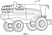
- FIG. 1 illustrates an agricultural harvester 10 such as a combine or the like applicable to the subject application.
- Located at the upper rear of the combine is an engine which is hidden from view by a cooler box 12.
- cooler box 12 includes a cooler box door 14 which substantially encases a circular screen 16 in which a flow of air passes through for communication with the internals of the cooler box.
- the cooler box 12 houses among other things a radiator of the combine.
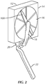
- FIG. 2 illustrates a suction wand 100 having a longitudinal rear face facingly engaging the circular screen 16.
- the suction wand is mounted adjacent the circular screen so as to rotate about an axis such that rotation of the tips of the suction wand forms a circle substantially matching the size of the circular screen 16 or slightly overlaying the circular screen.
- Extending from the suction wand 100 is a suction hose 18 operatively connected to a fan housing 20 and thereafter a discharge 22.
- the structure, function and operation of the cooler box, circular screen, suction hose and fan housing are known in the art and a detailed description of such components is not necessary for a complete understanding of the present aspects of the subject application. However, a typical cooler box and related components applicable to the subject application are disclosed in U.S. Patent No. 8,197,567 .
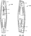
- the subject application provides a suction wand 100 as shown and configured in FIGS. 3A-3F .
- the suction wand 100 is an elongated wand having a hollow body 102 forming an elongated interior chamber 104 ( FIG. 3E ) that is in fluid communication with the suction hose 18 for generating a negative pressure within the hollow body.
- the suction wand 100 also includes a hub 106 for attaching to a rotary device such that the suction wand rotates about the hub or with the rotary device.
- the hub is located about a center of the elongated hollow body portion for connecting to the suction hose 18.
- the suction wand includes a pair of arms extending from the hub, i.e., a first arm or first end 108a and a second arm or second end 108b ( FIG. 3A ).
- the suction wand can alternatively be configured to be symmetric, asymmetric, or with more than two arms such as multiple arms extending from the hub 106.
- the shape of the hollow body 102 can be that of a rectangular prism but is preferably configured with the distal ends of the hollow body tapered inwardly.
- the rear face 110 ( FIG. 3B ) of the suction wand is configured with three slot openings or, simply, slots 112, 114 and 116 each in fluid communication with the interior of the hollow body 102 for allowing suction to be generated at the openings of each slot 112, 114 and 116.
- the first slot 112 is positioned about the first end of the suction wand and extends a length about 1 ⁇ 4 to 1/3 the longitudinal length of the suction wand.
- the second slot 114 extends from about the hub 106 a length about 1/3 of the longitudinal length of the suction wand.
- the third slot 116 is positioned about a second end of the suction wand opposite the first end and extends a length about 1 ⁇ 4 to 1/3 the longitudinal length of the suction wand.
- Each of the first, second and third slots 112, 114 and 116 have a width that is smaller than an overall width of the suction wand hollow body 102.
- the ratio of the width of any slot to the overall width of the hollow body can be 1/6, 1/5, 1 ⁇ 4, 1/3 or some other fraction.
- at least the rear face 110 of suction wand 100 includes a plurality of stiffening ribs formed therein in order to minimize flexure of the suction wand during rotation.
- the suction wand is configured with a throat region 118 about the second slot 114 so as to retard the flow of fluid communication within the interior of the hollow body between the hub and the third slot such that greater amounts of suction is preserved at the distal ends i.e., at the first and third slots 112, 116, compared to the middle sections of the suction wand i.e., about the second slot 114.
- the throat region 118 can be formed e.g., by a concave or U-shaped riser 120 extending inwardly of the hollow body 102 from its rear face.
- the throat region 118 effectively reduces the overall volume of space between the third slot 116 and the hub such that higher negative pressure about the third slot can be maintained.
- the slots 112, 114 and 116 are also configured to be tapered such that the distal ends of the slots are wider than the proximal ends i.e., ends closer to the hub 106.
- the slots are also configured as substantially rectangular or trapezoidal slots having their faces facingly engaging the circular screen 16.
- the first and third slots 112, 116 can optionally be configured to have substantially the same shape and positioned along the longitudinal length of the suction wand such that during rotation of the suction wand, the first slot 112 substantially covers the same area across the screen as the third slot 116 thereby providing double coverage of the same screen area. That is, the first slot opening 112 is spaced from the third slot opening 116 such that upon rotation of the suction wand the first slot opening defines a circular path that overlaps with a circular path defined by the third slot opening.
- the hollow body of the suction wand 100 extends further than the distal ends of the first and second slots 112, 116.
- the first and second slots 112, 116 are spaced slightly from the most distal ends of the suction wand which advantageously increases suction emanating from the ends of the first and second slots.
- the height H A at the tips of the suction wand 100 is also preferably configured to be as large as possible relative to that of height H B at the center of the suction wand. That is, the reduction in height H A relative to H B is minimized to preserve suction performance at the ends of the suction wand.
- H A can be 30%, 40%, 50%, 60%, 70%, 80%, 90% or some other percentage of the height of H B .
- suction power is better distributed to the ends of the suction wand. That is, suction within a conventional wand is greatest closer to the hub than at its tips.
- the riser 120 causes suction power or flow to be divided along the riser thereby resulting in lower suction at the second slot 114 and increasing suction at the third slot 116.
- the volume of space occupied by the riser facilitates the redistribution of flow and pressure along the suction wand.
- the lateral sides 122, 124 of the suction wand are also configured to taper inwardly extending from its posterior surface towards its anterior surface.
- the length of the second slot 114 extends a fixed distance so as to form an underlap with third slot 116 i.e., the second slot is spaced from the third slot. That is, the circular path defined by the second slot 114 is spaced from the circular path defined by the third slot 116 during rotation of the wand thereby advantageously preserving suction power across the suction wand.
- This underlap is also advantageous because suction forces extend slightly beyond the edges of the slots thereby negating the need for overlapping circular pathways and preserving suction power within the suction wand to fully cover the diameter of the screen despite the gap between the circular paths traversed by the second and third slots.
- FIG. 3C further shows that the outer shape of the wand 100 can be asymmetrical. That is, the first end of the wand in which the first slot 112 resides is slightly narrower in width than the second end of the wand in which the second and third slots 114, 116 reside.
- the purpose of this asymmetry is to provide greater negative air flow to the arm of the wand that contains multiple or more slots e.g., the second and third slots in order to compensate for the greater slot opening space created by the second and third slots. That is, air flow is biased toward the second and third slots in order to maintain sufficient suction through all slots of the suction wand.
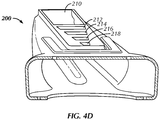
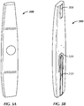
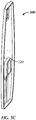
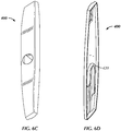
- FIGS. 4A-4E illustrate a suction wand 200 in accordance with another embodiment of the invention.
- Suction wand 200 is similarly constructed as suction wand 100 but with the following differences.
- the suction wand 200 has an overall shape configured as shown in FIGS. 4A through 4C .
- the suction wand 200 includes first 208, second 210, third 212, fourth 214, fifth 216 and sixth 218 slots each in fluid communication with an interior of a hollow body 202 for facingly engaging the screen of the cooler box.
- Each of the second through sixth slots 210, 212, 214, 216 and 218 are separated by a partition member of the hollow body.
- First slot 208 extends from adjacent or slightly spaced from a tip of the suction wand about a first end thereof a longitudinal length about 1 ⁇ 4 to 1/3 of the overall suction wand longitudinal length.
- the second slot 210 extends from adjacent or slightly spaced from a tip of the suction wand at a second end opposite the first end a longitudinal length about 1 ⁇ 4 to 1/3 of the suction wand.
- Each of the third through sixth slots 212, 214, 216 and 218 are positioned between the second slot 210 and a hub 206 about the second end of the elongated body of the suction wand.
- Each of the third through sixth slots 212, 214, 216 and 218 are also configured to have an opening progressively smaller in size than the preceding slot.
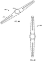
- FIGS. 5A-5D illustrate a suction wand 300 not in accordance with the invention.
- Suction wand 300 is similarly constructed as suction wand 100 but with the following differences.
- Suction wand 300 includes a first slot 308 and a second slot 310.
- the first slot 308 extends from adjacent or slightly spaced from a tip of the suction wand at a first end a longitudinal length about 1 ⁇ 4 to 1/3 of the overall suction wand longitudinal length.
- the second slot 310 extends from adjacent or slightly spaced from a tip of the suction wand at a second end opposite the first end and extends a longitudinal length of the suction wand from the tip of the second end to immediately adjacent the hub 306.
- the second slot 310 is also configured with a partial wall portion or riser 320 that circumscribes the second slot 310 and extends inwardly of the hollow body 302, but only partially circumscribing a circumference of the second slot, as best shown in FIG. 5C .
- the wall portion or riser 320 functions similarly to the aforementioned riser 120. That is, partial wall or riser 320 retards the flow of fluid communication within the interior of the hollow body nearest the hub such that greater amounts of suction is preserved at the distal ends of the slots compared to the middle sections of the suction wand i.e., about the central portion of the second slot 310.
- the partial wall 320 is also referred to as a U-shaped riser wherein both legs of the U extend substantially the same length.
- the partial wall is positioned about a proximal end of the second slot 310 e.g., between the slot and the hub.
- FIGS. 6A-6D illustrate a suction wand 400 not in accordance with the invention.
- Suction wand 400 is similarly constructed as suction wand 100 but with the following differences.
- the suction wand 400 has an overall shape configured as best shown in FIG. 6B .
- Suction wand 400 includes a first slot 408 and a second slot 410.
- the first slot 408 extends from adjacent or slightly spaced from a tip of the suction wand at a first end a longitudinal length about 1 ⁇ 4 to 1/3 of the overall suction wand longitudinal length.
- the second slot 410 extends from adjacent or slightly spaced from a tip of the suction wand at a second end opposite the first end and extends a longitudinal length of the suction wand from the tip of the second end to immediately adjacent the hub 406.
- FIGS. 6B and 6D illustrate that the second slot 410 is also configured with a partial wall or riser 420 that circumscribes the second slot 410 and extends inwardly of the hollow body 402, but only partially along the circumference of the second slot, as best shown in FIG. 6B .
- the partial wall 420 is also referred to as a U-shaped riser and is configured substantially the same as the U-shaped riser 320 except that one leg of the U-shaped riser extends further or is longer than the other. That is, the wall portion circumscribes a most proximal end of the second slot opening 410 and extends along a first lateral side of the second slot opening further distally than along a second lateral side of the second slot opening opposite the first lateral side.
- the partial wall is also positioned between the hub and the second slot.
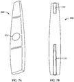
- FIGS. 7A-7C illustrate a suction wand 500 not in accordance with the invention.
- Suction wand 500 is similarly constructed as suction wand 100 but with the following differences.
- the suction wand 500 has an overall shape configured as best shown in FIG. 7B .
- Suction wand 500 includes a first slot 508 and a second slot 510.
- the first slot 508 extends from adjacent or slightly spaced from a tip of the suction wand at a first end a longitudinal length about 1 ⁇ 4 to 1/3 of the overall suction wand longitudinal length.
- the second slot 510 extends from adjacent or slightly spaced from a tip of the suction wand at a second end opposite the first end and extends a longitudinal length of the suction wand from the tip of the second end to immediately adjacent the hub 506.
- the second slot 510 of suction wand 500 also includes a riser or bump 520 that extends inwardly from the posterior surface (or facingly engaging surface) of the suction wand, as best shown in FIG. 7C , forming a throat region 518. That is, the throat region 518 is formed from the posterior wall or surface extending inwardly of the hollow body so as to be adjacent the anterior wall at least partially the longitudinal length of the second slot, thereby forming a region of restricted air flow from a tip of the suction wand to the hub region 506 of the suction wand.
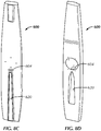
- FIGS. 8A-8E illustrate a suction wand 600 not in accordance with the invention.
- Suction wand 600 is similarly constructed as suction wand 500 but with the following differences.
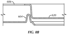
- the suction wand 600 additionally includes a flow retarder 604 ( FIGS. 8B-8E ) extending inwardly of the hollow body 602 from a posterior surface of the suction wand.
- the flow retarder 604 is an inwardly extending C-shaped wall segment positioned adjacent a proximal end of a wall portion or riser 620 extending inwardly of an anterior surface of the suction wand.
- Suction wand 600 has a hub 606 located about a center of the elongated hollow body portion for connecting to suction hose 18 ( FIG. 2 ) wherein the flow retarder is between the hub and the wall portion 620.
- the flow retarder and riser collectively form an increasingly restricted flow region for the flow of air from a distal end of the suction wand toward the hub of the suction wand. That is, suction is redistributed across the length of the wand 600 whereby it is greatest at distal ends of the wand and decreases radially inwardly in order to substantially uniformly remove debris from the entire surface of the circular screen 16 ( FIG. 2 ).
Landscapes
- Engineering & Computer Science (AREA)
- Mechanical Engineering (AREA)
- Chemical & Material Sciences (AREA)
- Environmental Sciences (AREA)
- General Engineering & Computer Science (AREA)
- Life Sciences & Earth Sciences (AREA)
- Combustion & Propulsion (AREA)
- Chemical Kinetics & Catalysis (AREA)
- Structures Of Non-Positive Displacement Pumps (AREA)
- Agricultural Chemicals And Associated Chemicals (AREA)
- Joints Allowing Movement (AREA)
- Heat-Exchange Devices With Radiators And Conduit Assemblies (AREA)
- Cleaning In General (AREA)
Claims (15)
- Saugarm (100, 200) für ein Kühlergehäuse (12) mit:einem länglichen Hohlkörper (102, 202) zur Befestigung an einem Saugschlauch (18); undeiner ersten Schlitzöffnung (112, 208), einer zweiten Schlitzöffnung (114, 210),dadurch gekennzeichnet, dassder Saugarm (100, 200) des Weiteren eine dritte Schlitzöffnung (116) aufweist, wobei jede der Schlitzöffnungen in Fluidverbindung mit einem Innenraum des Hohlkörpers (102, 202) ist, um zugewandt in ein Sieb (16) des Kühlergehäuses (12) einzugreifen.
- Saugarm (100, 200) nach Anspruch 1, der des Weiteren eine Nabe um einen Mittelpunkt des länglichen Hohlkörperabschnitts (102, 202) zur Verbindung mit dem Saugschlauch (18) aufweist.
- Saugarm (100, 200) nach Anspruch 1, wobei die ersten, zweiten und dritten Schlitzöffnungen (116) verjüngt sind.
- Saugarm (100, 200) nach Anspruch 1, der des Weiteren einen Verengungsbereich zwischen der zweiten Schlitzöffnung (114, 210) und der dritten Schlitzöffnung (116) aufweist.
- Saugarm (100, 200) nach Anspruch 1, wobei die erste Schlitzöffnung (112, 208) von der dritten Schlitzöffnung (116) derart beabstandet ist, dass bei Drehung des Saugarms (100, 200) die erste Schlitzöffnung (112, 208) eine Kreisbahn definiert, die mit einer Kreisbahn überlappt, die durch die dritte Schlitzöffnung (116) definiert ist.
- Saugarm (100, 200) nach Anspruch 1, wobei die zweite Schlitzöffnung (114, 210, 310, 410, 510) von der dritten Schlitzöffnung (116) derart beabstandet ist, dass bei Drehung des Saugarms (100, 200) die dritte Schlitzöffnung (116) eine Kreisbahn definiert, die zu einer durch die zweite Schlitzöffnung (114, 210) definierten Kreisbahn eine Lücke aufweist bzw. diese unterlappt.
- Saugarm (100, 200) nach Anspruch 1, wobei der längliche Hohlkörper (102, 202) asymmetrisch ist.
- Saugarm (100, 200) nach Anspruch 7, wobei der längliche Hohlkörper (102, 202) ein erstes Ende mit einer ersten Breite und zweites, dem ersten Ende gegenüberliegendes Ende mit einer zweiten Breite, die größer als die erste Breite ist, aufweist, um den Luftstrom zu dem zweiten Ende hin zu beeinflussen.
- Saugarm (100, 200) nach Anspruch 8, wobei die erste Schlitzöffnung (112, 208) um das erste Ende herum und die zweiten und dritten Schlitzöffnungen (116) um das zweite Ende herum angeordnet sind.
- Saugarm (100, 200) nach Anspruch 1, der des Weiteren eine vierte Schlitzöffnung, eine fünfte Schlitzöffnung und eine sechste Schlitzöffnung aufweist, die jeweils in Fluidverbindung mit dem Inneren des Hohlkörpers (102, 202) sind, um zugewandt in das Sieb (16) des Kühlergehäuses (12) einzugreifen.
- Saugarm (100, 200) nach Anspruch 10, wobei der längliche Hohlkörper (102, 202) ein erstes Ende und ein dem ersten Ende gegenüberliegendes zweites Ende aufweist, und wobei die erste Schlitzöffnung (112, 208) um das erste Ende angeordnet ist und die zweiten, dritten, vierten, fünften und sechsten Schlitzöffnungen jeweils um das zweite Ende angeordnet sind.
- Saugarm (100, 200) nach Anspruch 10, wobei die zweiten, dritten, vierten, fünften und sechsten Schlitzöffnungen in ihrer Größe derart bemessen sind, dass sie fortschreitend kleiner werden.
- Saugarm (100, 200) nach Anspruch 1, der des Weiteren einen Wandabschnitt aufweist, der sich von dem länglichen Hohlkörper (102, 202) einwärts erstreckt und einen Umfang der zweiten Schlitzöffnung (114, 210) teilweise umschreibt.
- Saugarm (100, 200) nach Anspruch 13, wobei der Wandabschnitt ein nächstes Ende der zweiten Schlitzöffnung (114, 210) umschreibt und sich entlang einer ersten Seite der zweiten Schlitzöffnung (114, 210) weiter entfernt erstreckt als entlang einer zweiten Seite der zweiten Schlitzöffnung (114, 210), die gegenüber der ersten Seite liegt.
- Saugarm (100, 200) nach Anspruch 13, die des Weiteren eine Stromverzögerungseinrichtung aufweist, die sich von einer hinteren Wandfläche angrenzend an den Wandabschnitt einwärts des länglichen Hohlkörpers (102, 202) erstreckt.
Applications Claiming Priority (2)
| Application Number | Priority Date | Filing Date | Title |
|---|---|---|---|
| US201462006468P | 2014-06-02 | 2014-06-02 | |
| PCT/US2015/033762 WO2015191334A1 (en) | 2014-06-02 | 2015-06-02 | Suction wand for a cooler box |
Publications (2)
| Publication Number | Publication Date |
|---|---|
| EP3149305A1 EP3149305A1 (de) | 2017-04-05 |
| EP3149305B1 true EP3149305B1 (de) | 2018-05-30 |
Family
ID=53398228
Family Applications (1)
| Application Number | Title | Priority Date | Filing Date |
|---|---|---|---|
| EP15729312.7A Active EP3149305B1 (de) | 2014-06-02 | 2015-06-02 | Saugarm für einen kühlerkasten |
Country Status (4)
| Country | Link |
|---|---|
| US (1) | US20170107893A1 (de) |
| EP (1) | EP3149305B1 (de) |
| BR (1) | BR112016028367B1 (de) |
| WO (1) | WO2015191334A1 (de) |
Cited By (1)
| Publication number | Priority date | Publication date | Assignee | Title |
|---|---|---|---|---|
| EP4082323A1 (de) | 2021-04-30 | 2022-11-02 | CLAAS Selbstfahrende Erntemaschinen GmbH | Siebeinrichtung mit zumindest einer absaugdüse |
Families Citing this family (1)
| Publication number | Priority date | Publication date | Assignee | Title |
|---|---|---|---|---|
| US11506111B2 (en) * | 2020-04-08 | 2022-11-22 | Deere & Company | Work vehicle having an intake cleaning system with an alignment mechanism |
Family Cites Families (6)
| Publication number | Priority date | Publication date | Assignee | Title |
|---|---|---|---|---|
| US2601704A (en) * | 1950-07-25 | 1952-07-01 | Hardwicke Etter Co | Screen cleaning apparatus |
| US4036613A (en) * | 1976-08-25 | 1977-07-19 | Woods Metal Company, Inc. | Rotary sweep arm for self-cleaning filter apparatus |
| DE3175314D1 (en) * | 1981-11-14 | 1986-10-16 | Deere & Co | Cleaning device to clean the air filter of a cooling air-casing comprising a fan-blown radiator |
| US5466271A (en) * | 1994-04-29 | 1995-11-14 | Horvat; Ivan J. | Pre-filter with rotating nozzle |
| US6946011B2 (en) * | 2003-03-18 | 2005-09-20 | The Babcock & Wilcox Company | Intermittent mixer with low pressure drop |
| US8097050B2 (en) * | 2008-02-26 | 2012-01-17 | Cnh America Llc | Rotary vacuum apparatus for air screen |
-
2015
- 2015-06-02 EP EP15729312.7A patent/EP3149305B1/de active Active
- 2015-06-02 WO PCT/US2015/033762 patent/WO2015191334A1/en not_active Ceased
- 2015-06-02 US US15/315,785 patent/US20170107893A1/en not_active Abandoned
- 2015-06-02 BR BR112016028367-8A patent/BR112016028367B1/pt active IP Right Grant
Non-Patent Citations (1)
| Title |
|---|
| None * |
Cited By (3)
| Publication number | Priority date | Publication date | Assignee | Title |
|---|---|---|---|---|
| EP4082323A1 (de) | 2021-04-30 | 2022-11-02 | CLAAS Selbstfahrende Erntemaschinen GmbH | Siebeinrichtung mit zumindest einer absaugdüse |
| DE102021111281A1 (de) | 2021-04-30 | 2022-11-03 | Claas Selbstfahrende Erntemaschinen Gmbh | Siebeinrichtung mit zumindest einer Absaugdüse |
| US12284941B2 (en) | 2021-04-30 | 2025-04-29 | Claas Selbstfahrende Erntemaschinen Gmbh | Screening device with at least one suction nozzle |
Also Published As
| Publication number | Publication date |
|---|---|
| BR112016028367B1 (pt) | 2022-08-23 |
| WO2015191334A1 (en) | 2015-12-17 |
| BR112016028367A2 (pt) | 2017-08-22 |
| US20170107893A1 (en) | 2017-04-20 |
| EP3149305A1 (de) | 2017-04-05 |
Similar Documents
| Publication | Publication Date | Title |
|---|---|---|
| EP2923554B1 (de) | Rasenmäher | |
| ES2568757T5 (es) | Cortacésped | |
| EP3149305B1 (de) | Saugarm für einen kühlerkasten | |
| WO2012106667A2 (en) | Blade with debris disbursing air lift | |
| CN110121257A (zh) | 切割刀片及割草机 | |
| BR102017014759B1 (pt) | Espalhador de resíduo de cultura e colheitadeira combinada | |
| US11234365B2 (en) | Baffles for mower deck | |
| BR102016022930A2 (pt) | veículo agrícola e sistema de manuseio de resíduo para uma colheitadeira agrícola | |
| BR102017020879B1 (pt) | Colheitadeira e plataforma de uma colheitadeira | |
| ES2238514T3 (es) | Maquina para segar un producto cosechable de tipo tallo. | |
| US9485913B2 (en) | Converging drum and stripper arrangement | |
| BR112015027875B1 (pt) | plataforma para uma colheitadeira agrícola combinada | |
| US9750192B2 (en) | Integrated fan and axle arrangement for an agricultural vehicle | |
| US9591804B2 (en) | Oscillating pan of an agricultural combine having a flow control guide vane | |
| BRPI0602893B1 (pt) | Ventoinha para um cortador de palha, cortador de palha, palheta de vetoinha, e, unidade de colheitadeira agrícola | |
| SE511119C2 (sv) | Rotorenhet och gräsklippare med sådan rotorenhet för avklippning av gräs vid flera nivåer | |
| SE539614C2 (en) | Cutting blade and lawn mower | |
| BR102020006882A2 (pt) | Divisor de colheita para uma plataforma de milho | |
| US20120210691A1 (en) | Bell Knife for Rotary Mower | |
| BR102019003443A2 (pt) | guia de safra ativo para uma segadora | |
| US9649704B2 (en) | Debris vent for a saw blade housing | |
| ES2879302T3 (es) | Esparcidor de residuos de cultivos para una cosechadora combinada | |
| BR102017015425A2 (pt) | Platform for a combined harvest | |
| JP7641942B2 (ja) | 茎葉処理機 | |
| BR102014017335B1 (pt) | rotor para um conjunto exaustor de uma máquina agrícola |
Legal Events
| Date | Code | Title | Description |
|---|---|---|---|
| STAA | Information on the status of an ep patent application or granted ep patent |
Free format text: STATUS: THE INTERNATIONAL PUBLICATION HAS BEEN MADE |
|
| PUAI | Public reference made under article 153(3) epc to a published international application that has entered the european phase |
Free format text: ORIGINAL CODE: 0009012 |
|
| STAA | Information on the status of an ep patent application or granted ep patent |
Free format text: STATUS: REQUEST FOR EXAMINATION WAS MADE |
|
| 17P | Request for examination filed |
Effective date: 20170102 |
|
| AK | Designated contracting states |
Kind code of ref document: A1 Designated state(s): AL AT BE BG CH CY CZ DE DK EE ES FI FR GB GR HR HU IE IS IT LI LT LU LV MC MK MT NL NO PL PT RO RS SE SI SK SM TR |
|
| AX | Request for extension of the european patent |
Extension state: BA ME |
|
| RIN1 | Information on inventor provided before grant (corrected) |
Inventor name: IVEY, CAMERON JACKSON Inventor name: PASCHAL, DAVID Inventor name: TAMAMIDIS, PANOS Inventor name: DAVENPORT, RAYMOND SAMUEL TREY Inventor name: SARPOTDAR, SHEKHAR Inventor name: GYENES, MATTHEW JOHN Inventor name: MERKEL, MARK |
|
| DAV | Request for validation of the european patent (deleted) | ||
| DAX | Request for extension of the european patent (deleted) | ||
| GRAP | Despatch of communication of intention to grant a patent |
Free format text: ORIGINAL CODE: EPIDOSNIGR1 |
|
| STAA | Information on the status of an ep patent application or granted ep patent |
Free format text: STATUS: GRANT OF PATENT IS INTENDED |
|
| RAP1 | Party data changed (applicant data changed or rights of an application transferred) |
Owner name: CNH INDUSTRIAL BELGIUM N.V. |
|
| INTG | Intention to grant announced |
Effective date: 20171221 |
|
| GRAS | Grant fee paid |
Free format text: ORIGINAL CODE: EPIDOSNIGR3 |
|
| GRAA | (expected) grant |
Free format text: ORIGINAL CODE: 0009210 |
|
| STAA | Information on the status of an ep patent application or granted ep patent |
Free format text: STATUS: THE PATENT HAS BEEN GRANTED |
|
| REG | Reference to a national code |
Ref country code: FR Ref legal event code: PLFP Year of fee payment: 4 |
|
| AK | Designated contracting states |
Kind code of ref document: B1 Designated state(s): AL AT BE BG CH CY CZ DE DK EE ES FI FR GB GR HR HU IE IS IT LI LT LU LV MC MK MT NL NO PL PT RO RS SE SI SK SM TR |
|
| REG | Reference to a national code |
Ref country code: GB Ref legal event code: FG4D |
|
| REG | Reference to a national code |
Ref country code: CH Ref legal event code: EP |
|
| REG | Reference to a national code |
Ref country code: AT Ref legal event code: REF Ref document number: 1003823 Country of ref document: AT Kind code of ref document: T Effective date: 20180615 |
|
| REG | Reference to a national code |
Ref country code: IE Ref legal event code: FG4D |
|
| REG | Reference to a national code |
Ref country code: DE Ref legal event code: R096 Ref document number: 602015011562 Country of ref document: DE |
|
| REG | Reference to a national code |
Ref country code: NL Ref legal event code: MP Effective date: 20180530 |
|
| REG | Reference to a national code |
Ref country code: LT Ref legal event code: MG4D |
|
| PG25 | Lapsed in a contracting state [announced via postgrant information from national office to epo] |
Ref country code: BG Free format text: LAPSE BECAUSE OF FAILURE TO SUBMIT A TRANSLATION OF THE DESCRIPTION OR TO PAY THE FEE WITHIN THE PRESCRIBED TIME-LIMIT Effective date: 20180830 Ref country code: ES Free format text: LAPSE BECAUSE OF FAILURE TO SUBMIT A TRANSLATION OF THE DESCRIPTION OR TO PAY THE FEE WITHIN THE PRESCRIBED TIME-LIMIT Effective date: 20180530 Ref country code: CY Free format text: LAPSE BECAUSE OF FAILURE TO SUBMIT A TRANSLATION OF THE DESCRIPTION OR TO PAY THE FEE WITHIN THE PRESCRIBED TIME-LIMIT Effective date: 20180530 Ref country code: LT Free format text: LAPSE BECAUSE OF FAILURE TO SUBMIT A TRANSLATION OF THE DESCRIPTION OR TO PAY THE FEE WITHIN THE PRESCRIBED TIME-LIMIT Effective date: 20180530 Ref country code: NO Free format text: LAPSE BECAUSE OF FAILURE TO SUBMIT A TRANSLATION OF THE DESCRIPTION OR TO PAY THE FEE WITHIN THE PRESCRIBED TIME-LIMIT Effective date: 20180830 Ref country code: FI Free format text: LAPSE BECAUSE OF FAILURE TO SUBMIT A TRANSLATION OF THE DESCRIPTION OR TO PAY THE FEE WITHIN THE PRESCRIBED TIME-LIMIT Effective date: 20180530 Ref country code: SE Free format text: LAPSE BECAUSE OF FAILURE TO SUBMIT A TRANSLATION OF THE DESCRIPTION OR TO PAY THE FEE WITHIN THE PRESCRIBED TIME-LIMIT Effective date: 20180530 |
|
| PG25 | Lapsed in a contracting state [announced via postgrant information from national office to epo] |
Ref country code: HR Free format text: LAPSE BECAUSE OF FAILURE TO SUBMIT A TRANSLATION OF THE DESCRIPTION OR TO PAY THE FEE WITHIN THE PRESCRIBED TIME-LIMIT Effective date: 20180530 Ref country code: RS Free format text: LAPSE BECAUSE OF FAILURE TO SUBMIT A TRANSLATION OF THE DESCRIPTION OR TO PAY THE FEE WITHIN THE PRESCRIBED TIME-LIMIT Effective date: 20180530 Ref country code: GR Free format text: LAPSE BECAUSE OF FAILURE TO SUBMIT A TRANSLATION OF THE DESCRIPTION OR TO PAY THE FEE WITHIN THE PRESCRIBED TIME-LIMIT Effective date: 20180831 Ref country code: LV Free format text: LAPSE BECAUSE OF FAILURE TO SUBMIT A TRANSLATION OF THE DESCRIPTION OR TO PAY THE FEE WITHIN THE PRESCRIBED TIME-LIMIT Effective date: 20180530 |
|
| REG | Reference to a national code |
Ref country code: AT Ref legal event code: MK05 Ref document number: 1003823 Country of ref document: AT Kind code of ref document: T Effective date: 20180530 |
|
| PG25 | Lapsed in a contracting state [announced via postgrant information from national office to epo] |
Ref country code: NL Free format text: LAPSE BECAUSE OF FAILURE TO SUBMIT A TRANSLATION OF THE DESCRIPTION OR TO PAY THE FEE WITHIN THE PRESCRIBED TIME-LIMIT Effective date: 20180530 |
|
| PG25 | Lapsed in a contracting state [announced via postgrant information from national office to epo] |
Ref country code: SK Free format text: LAPSE BECAUSE OF FAILURE TO SUBMIT A TRANSLATION OF THE DESCRIPTION OR TO PAY THE FEE WITHIN THE PRESCRIBED TIME-LIMIT Effective date: 20180530 Ref country code: RO Free format text: LAPSE BECAUSE OF FAILURE TO SUBMIT A TRANSLATION OF THE DESCRIPTION OR TO PAY THE FEE WITHIN THE PRESCRIBED TIME-LIMIT Effective date: 20180530 Ref country code: CZ Free format text: LAPSE BECAUSE OF FAILURE TO SUBMIT A TRANSLATION OF THE DESCRIPTION OR TO PAY THE FEE WITHIN THE PRESCRIBED TIME-LIMIT Effective date: 20180530 Ref country code: PL Free format text: LAPSE BECAUSE OF FAILURE TO SUBMIT A TRANSLATION OF THE DESCRIPTION OR TO PAY THE FEE WITHIN THE PRESCRIBED TIME-LIMIT Effective date: 20180530 Ref country code: EE Free format text: LAPSE BECAUSE OF FAILURE TO SUBMIT A TRANSLATION OF THE DESCRIPTION OR TO PAY THE FEE WITHIN THE PRESCRIBED TIME-LIMIT Effective date: 20180530 Ref country code: AT Free format text: LAPSE BECAUSE OF FAILURE TO SUBMIT A TRANSLATION OF THE DESCRIPTION OR TO PAY THE FEE WITHIN THE PRESCRIBED TIME-LIMIT Effective date: 20180530 Ref country code: DK Free format text: LAPSE BECAUSE OF FAILURE TO SUBMIT A TRANSLATION OF THE DESCRIPTION OR TO PAY THE FEE WITHIN THE PRESCRIBED TIME-LIMIT Effective date: 20180530 |
|
| REG | Reference to a national code |
Ref country code: CH Ref legal event code: PL |
|
| PG25 | Lapsed in a contracting state [announced via postgrant information from national office to epo] |
Ref country code: SM Free format text: LAPSE BECAUSE OF FAILURE TO SUBMIT A TRANSLATION OF THE DESCRIPTION OR TO PAY THE FEE WITHIN THE PRESCRIBED TIME-LIMIT Effective date: 20180530 |
|
| REG | Reference to a national code |
Ref country code: DE Ref legal event code: R097 Ref document number: 602015011562 Country of ref document: DE |
|
| REG | Reference to a national code |
Ref country code: IE Ref legal event code: MM4A |
|
| PG25 | Lapsed in a contracting state [announced via postgrant information from national office to epo] |
Ref country code: LU Free format text: LAPSE BECAUSE OF NON-PAYMENT OF DUE FEES Effective date: 20180602 Ref country code: MC Free format text: LAPSE BECAUSE OF FAILURE TO SUBMIT A TRANSLATION OF THE DESCRIPTION OR TO PAY THE FEE WITHIN THE PRESCRIBED TIME-LIMIT Effective date: 20180530 |
|
| PLBE | No opposition filed within time limit |
Free format text: ORIGINAL CODE: 0009261 |
|
| STAA | Information on the status of an ep patent application or granted ep patent |
Free format text: STATUS: NO OPPOSITION FILED WITHIN TIME LIMIT |
|
| PG25 | Lapsed in a contracting state [announced via postgrant information from national office to epo] |
Ref country code: LI Free format text: LAPSE BECAUSE OF NON-PAYMENT OF DUE FEES Effective date: 20180630 Ref country code: IE Free format text: LAPSE BECAUSE OF NON-PAYMENT OF DUE FEES Effective date: 20180602 Ref country code: CH Free format text: LAPSE BECAUSE OF NON-PAYMENT OF DUE FEES Effective date: 20180630 |
|
| 26N | No opposition filed |
Effective date: 20190301 |
|
| PG25 | Lapsed in a contracting state [announced via postgrant information from national office to epo] |
Ref country code: SI Free format text: LAPSE BECAUSE OF FAILURE TO SUBMIT A TRANSLATION OF THE DESCRIPTION OR TO PAY THE FEE WITHIN THE PRESCRIBED TIME-LIMIT Effective date: 20180530 |
|
| PG25 | Lapsed in a contracting state [announced via postgrant information from national office to epo] |
Ref country code: AL Free format text: LAPSE BECAUSE OF FAILURE TO SUBMIT A TRANSLATION OF THE DESCRIPTION OR TO PAY THE FEE WITHIN THE PRESCRIBED TIME-LIMIT Effective date: 20180530 |
|
| PG25 | Lapsed in a contracting state [announced via postgrant information from national office to epo] |
Ref country code: MT Free format text: LAPSE BECAUSE OF NON-PAYMENT OF DUE FEES Effective date: 20180602 |
|
| PG25 | Lapsed in a contracting state [announced via postgrant information from national office to epo] |
Ref country code: TR Free format text: LAPSE BECAUSE OF FAILURE TO SUBMIT A TRANSLATION OF THE DESCRIPTION OR TO PAY THE FEE WITHIN THE PRESCRIBED TIME-LIMIT Effective date: 20180530 |
|
| PG25 | Lapsed in a contracting state [announced via postgrant information from national office to epo] |
Ref country code: PT Free format text: LAPSE BECAUSE OF FAILURE TO SUBMIT A TRANSLATION OF THE DESCRIPTION OR TO PAY THE FEE WITHIN THE PRESCRIBED TIME-LIMIT Effective date: 20180530 |
|
| PG25 | Lapsed in a contracting state [announced via postgrant information from national office to epo] |
Ref country code: HU Free format text: LAPSE BECAUSE OF FAILURE TO SUBMIT A TRANSLATION OF THE DESCRIPTION OR TO PAY THE FEE WITHIN THE PRESCRIBED TIME-LIMIT; INVALID AB INITIO Effective date: 20150602 Ref country code: MK Free format text: LAPSE BECAUSE OF NON-PAYMENT OF DUE FEES Effective date: 20180530 |
|
| PG25 | Lapsed in a contracting state [announced via postgrant information from national office to epo] |
Ref country code: IS Free format text: LAPSE BECAUSE OF FAILURE TO SUBMIT A TRANSLATION OF THE DESCRIPTION OR TO PAY THE FEE WITHIN THE PRESCRIBED TIME-LIMIT Effective date: 20180930 |
|
| PGFP | Annual fee paid to national office [announced via postgrant information from national office to epo] |
Ref country code: BE Payment date: 20230630 Year of fee payment: 9 |
|
| PG25 | Lapsed in a contracting state [announced via postgrant information from national office to epo] |
Ref country code: BE Free format text: LAPSE BECAUSE OF NON-PAYMENT OF DUE FEES Effective date: 20240630 |
|
| REG | Reference to a national code |
Ref country code: BE Ref legal event code: MM Effective date: 20240630 |
|
| PGFP | Annual fee paid to national office [announced via postgrant information from national office to epo] |
Ref country code: DE Payment date: 20250626 Year of fee payment: 11 |
|
| PGFP | Annual fee paid to national office [announced via postgrant information from national office to epo] |
Ref country code: GB Payment date: 20250617 Year of fee payment: 11 |
|
| PGFP | Annual fee paid to national office [announced via postgrant information from national office to epo] |
Ref country code: FR Payment date: 20250624 Year of fee payment: 11 |
|
| PGFP | Annual fee paid to national office [announced via postgrant information from national office to epo] |
Ref country code: IT Payment date: 20250623 Year of fee payment: 11 |