EP3150367B1 - Apparatus for processing a flexible material - Google Patents
Apparatus for processing a flexible material Download PDFInfo
- Publication number
- EP3150367B1 EP3150367B1 EP16190570.8A EP16190570A EP3150367B1 EP 3150367 B1 EP3150367 B1 EP 3150367B1 EP 16190570 A EP16190570 A EP 16190570A EP 3150367 B1 EP3150367 B1 EP 3150367B1
- Authority
- EP
- European Patent Office
- Prior art keywords
- roller
- cutting
- contact
- adjustment device
- pair
- Prior art date
- Legal status (The legal status is an assumption and is not a legal conclusion. Google has not performed a legal analysis and makes no representation as to the accuracy of the status listed.)
- Active
Links
Images




Classifications
-
- B—PERFORMING OPERATIONS; TRANSPORTING
- B26—HAND CUTTING TOOLS; CUTTING; SEVERING
- B26D—CUTTING; DETAILS COMMON TO MACHINES FOR PERFORATING, PUNCHING, CUTTING-OUT, STAMPING-OUT OR SEVERING
- B26D7/00—Details of apparatus for cutting, cutting-out, stamping-out, punching, perforating, or severing by means other than cutting
- B26D7/26—Means for mounting or adjusting the cutting member; Means for adjusting the stroke of the cutting member
- B26D7/2628—Means for adjusting the position of the cutting member
- B26D7/2635—Means for adjusting the position of the cutting member for circular cutters
-
- B—PERFORMING OPERATIONS; TRANSPORTING
- B26—HAND CUTTING TOOLS; CUTTING; SEVERING
- B26D—CUTTING; DETAILS COMMON TO MACHINES FOR PERFORATING, PUNCHING, CUTTING-OUT, STAMPING-OUT OR SEVERING
- B26D1/00—Cutting through work characterised by the nature or movement of the cutting member or particular materials not otherwise provided for; Apparatus or machines therefor; Cutting members therefor
- B26D1/01—Cutting through work characterised by the nature or movement of the cutting member or particular materials not otherwise provided for; Apparatus or machines therefor; Cutting members therefor involving a cutting member which does not travel with the work
- B26D1/12—Cutting through work characterised by the nature or movement of the cutting member or particular materials not otherwise provided for; Apparatus or machines therefor; Cutting members therefor involving a cutting member which does not travel with the work having a cutting member moving about an axis
- B26D1/14—Cutting through work characterised by the nature or movement of the cutting member or particular materials not otherwise provided for; Apparatus or machines therefor; Cutting members therefor involving a cutting member which does not travel with the work having a cutting member moving about an axis with a circular cutting member, e.g. disc cutter
- B26D1/24—Cutting through work characterised by the nature or movement of the cutting member or particular materials not otherwise provided for; Apparatus or machines therefor; Cutting members therefor involving a cutting member which does not travel with the work having a cutting member moving about an axis with a circular cutting member, e.g. disc cutter coacting with another disc cutter
- B26D1/245—Cutting through work characterised by the nature or movement of the cutting member or particular materials not otherwise provided for; Apparatus or machines therefor; Cutting members therefor involving a cutting member which does not travel with the work having a cutting member moving about an axis with a circular cutting member, e.g. disc cutter coacting with another disc cutter for thin material, e.g. for sheets, strips or the like
-
- B—PERFORMING OPERATIONS; TRANSPORTING
- B26—HAND CUTTING TOOLS; CUTTING; SEVERING
- B26D—CUTTING; DETAILS COMMON TO MACHINES FOR PERFORATING, PUNCHING, CUTTING-OUT, STAMPING-OUT OR SEVERING
- B26D7/00—Details of apparatus for cutting, cutting-out, stamping-out, punching, perforating, or severing by means other than cutting
- B26D7/26—Means for mounting or adjusting the cutting member; Means for adjusting the stroke of the cutting member
- B26D7/2628—Means for adjusting the position of the cutting member
- B26D7/265—Journals, bearings or supports for positioning rollers or cylinders relatively to each other
-
- B—PERFORMING OPERATIONS; TRANSPORTING
- B26—HAND CUTTING TOOLS; CUTTING; SEVERING
- B26F—PERFORATING; PUNCHING; CUTTING-OUT; STAMPING-OUT; SEVERING BY MEANS OTHER THAN CUTTING
- B26F1/00—Perforating; Punching; Cutting-out; Stamping-out; Apparatus therefor
- B26F1/38—Cutting-out; Stamping-out
- B26F1/384—Cutting-out; Stamping-out using rotating drums
-
- B—PERFORMING OPERATIONS; TRANSPORTING
- B31—MAKING ARTICLES OF PAPER, CARDBOARD OR MATERIAL WORKED IN A MANNER ANALOGOUS TO PAPER; WORKING PAPER, CARDBOARD OR MATERIAL WORKED IN A MANNER ANALOGOUS TO PAPER
- B31D—MAKING ARTICLES OF PAPER, CARDBOARD OR MATERIAL WORKED IN A MANNER ANALOGOUS TO PAPER, NOT PROVIDED FOR IN SUBCLASSES B31B OR B31C
- B31D1/00—Multiple-step processes for making flat articles ; Making flat articles
- B31D1/02—Multiple-step processes for making flat articles ; Making flat articles the articles being labels or tags
- B31D1/021—Making adhesive labels having a multilayered structure, e.g. provided on carrier webs
-
- B—PERFORMING OPERATIONS; TRANSPORTING
- B31—MAKING ARTICLES OF PAPER, CARDBOARD OR MATERIAL WORKED IN A MANNER ANALOGOUS TO PAPER; WORKING PAPER, CARDBOARD OR MATERIAL WORKED IN A MANNER ANALOGOUS TO PAPER
- B31D—MAKING ARTICLES OF PAPER, CARDBOARD OR MATERIAL WORKED IN A MANNER ANALOGOUS TO PAPER, NOT PROVIDED FOR IN SUBCLASSES B31B OR B31C
- B31D1/00—Multiple-step processes for making flat articles ; Making flat articles
- B31D1/02—Multiple-step processes for making flat articles ; Making flat articles the articles being labels or tags
- B31D1/026—Cutting or perforating
-
- B—PERFORMING OPERATIONS; TRANSPORTING
- B26—HAND CUTTING TOOLS; CUTTING; SEVERING
- B26D—CUTTING; DETAILS COMMON TO MACHINES FOR PERFORATING, PUNCHING, CUTTING-OUT, STAMPING-OUT OR SEVERING
- B26D1/00—Cutting through work characterised by the nature or movement of the cutting member or particular materials not otherwise provided for; Apparatus or machines therefor; Cutting members therefor
- B26D1/01—Cutting through work characterised by the nature or movement of the cutting member or particular materials not otherwise provided for; Apparatus or machines therefor; Cutting members therefor involving a cutting member which does not travel with the work
- B26D1/12—Cutting through work characterised by the nature or movement of the cutting member or particular materials not otherwise provided for; Apparatus or machines therefor; Cutting members therefor involving a cutting member which does not travel with the work having a cutting member moving about an axis
- B26D1/25—Cutting through work characterised by the nature or movement of the cutting member or particular materials not otherwise provided for; Apparatus or machines therefor; Cutting members therefor involving a cutting member which does not travel with the work having a cutting member moving about an axis with a non-circular cutting member
- B26D1/34—Cutting through work characterised by the nature or movement of the cutting member or particular materials not otherwise provided for; Apparatus or machines therefor; Cutting members therefor involving a cutting member which does not travel with the work having a cutting member moving about an axis with a non-circular cutting member moving about an axis parallel to the line of cut
- B26D1/40—Cutting through work characterised by the nature or movement of the cutting member or particular materials not otherwise provided for; Apparatus or machines therefor; Cutting members therefor involving a cutting member which does not travel with the work having a cutting member moving about an axis with a non-circular cutting member moving about an axis parallel to the line of cut and coacting with a rotary member
- B26D1/405—Cutting through work characterised by the nature or movement of the cutting member or particular materials not otherwise provided for; Apparatus or machines therefor; Cutting members therefor involving a cutting member which does not travel with the work having a cutting member moving about an axis with a non-circular cutting member moving about an axis parallel to the line of cut and coacting with a rotary member for thin material, e.g. for sheets, strips or the like
-
- B—PERFORMING OPERATIONS; TRANSPORTING
- B26—HAND CUTTING TOOLS; CUTTING; SEVERING
- B26D—CUTTING; DETAILS COMMON TO MACHINES FOR PERFORATING, PUNCHING, CUTTING-OUT, STAMPING-OUT OR SEVERING
- B26D7/00—Details of apparatus for cutting, cutting-out, stamping-out, punching, perforating, or severing by means other than cutting
- B26D2007/0012—Details, accessories or auxiliary or special operations not otherwise provided for
- B26D2007/005—Details, accessories or auxiliary or special operations not otherwise provided for cutters, e.g. guillotines, used in a label maker or printer
Definitions
- the invention concerns an apparatus for processing a flexible material, such as a paper material or a polymer film, in particular in the form of a continuous strip.
- the apparatus of the invention can be used as a cutting apparatus, in particular for obtaining labels destined to be applied on containers, such as bottles, jars, trays or others besides, to be used in the food, cosmetic sector or the like.
- Cutting apparatus comprise a cutting roller and an counter roller, which cooperate for cutting labels from a continuous strip of flexible material.
- the strip passes through an interspace defined between the cutting roller and the counter roller and is cut by corresponding blades included in a cutting die supported by the cutting roller.
- Respective circular rings are mounted at each end of the cutting roller and the counter roller, with respect to which the cutting roller and the counter roller are rotatable.
- the circular rings are instead arranged in a fixed position.
- Each circular ring associated to the cutting roller is arranged in contact with the corresponding circular ring associated to the counter roller.
- the apparatus of known type further comprises a pressing device for pressing the cutting roller towards the counter roller with a predetermined pressure, so that the cutting roller can cut the flexible material.
- the pressing device comprises two pairs of wheels, each pair of wheels being arranged in contact with a circular ring associated to an end of the cutting roller.
- the wheels of a pair are united to one another by a connecting element, the position of which can be modified thanks to a mechanical drive system, with a consequent varying of the pressure with which the cutting roller is pushed towards the counter roller.
- a defect of the cutting apparatus of known type is that the apparatus enable varying the thickness of the material to be cut and/or of the cutting die within very strict limits.
- the pressure with which the cutting roller is pushed towards the counter roller it is possible to make the system more rigid or alternatively more deformable, which has a rather limited influence on the relative position of the contrast roller and the cutting roller and, consequently, on the interval in which it can vary the thickness of the material to be cut and/or of the cutting die.
- a further defect of the cutting apparatus of known type is that the regulations that have to be made to make the apparatus able to cut materials having a different thickness and/or to work with cutting dies of different thickness are rather complicated.
- the regulation of the pressure is not linearly translated in a variation of the reciprocal position of the cutting roller and the counter roller. Consequently, many attempts are necessary as well as a considerable experience on the part of the operator to modify the settings of the cutting apparatus acting on the pressing device.
- the cutting apparatus of known type do not enable using cutting dies which, following irregular wear, have a different thickness to the two ends of the cutting roller.
- An aim of the invention is to improve the known apparatus for processing a flexible material, in particular cutting apparatus.
- a further aim is to provide an apparatus for processing a flexible material with a work tool, in which it is possible easily to modify the thickness of the flexible material to be processed.
- a further aim is to provide an apparatus for processing a flexible material with a work tool, in which it is possible to use work tools having different thicknesses from one another, passing from a tool to another with relative ease.
- a still further aim is to provide an apparatus for processing a flexible material with a work tool, which can operate with success also in a case in which the work tool has a variable thickness, due to irregular wear.
- the apparatus of the invention enables regulating the relative position of the first roller and the second roller, independently of the pressure with which the rollers are pushed towards one another by the relative pressing device. Owing to the position adjustment device, it is in fact possible to directly regulate the relative position of the first roller and the second roller, without having to act on the pressure applied by the pressing device. The relative position of the first roller and the second roller can therefore be regulated in a more immediate and rapid way with respect to the known apparatus, even by operators having little expertise.
- first roller and the second roller extend along respective axes.
- the position adjustment device is configured for modifying the distance between the axes along which the first roller and respectively the second roller extend.
- the position adjustment device comprises a front adjustment device associated to a front end of the first roller and of the second roller, and a rear adjustment device associated to a rear end of the first roller and of the second roller.
- the front adjustment device and the rear adjustment device are independent of one another.
- the apparatus can also be made suitable for operating with unevenly worn work tools, i.e. which have, at an end of the first roller and the second roller, a different thickness with respect to the thickness that the work tool has at the other end of the first roller and the second roller. This enables maximising the working life of the work tool, and consequently limiting down times and the costs required for replacing the work tool.
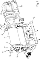
- Figure 1 illustrates a cutting apparatus 1, which can be used for cutting discrete portions starting from a flexible material, in particular a material in a continuous strip.
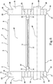
- the cutting apparatus 1 is particularly suitable for producing labels, in particular self-adhesive labels, starting from a strip material 14 the structure of which can be of the type schematically shown in figure 6 .
- the strip material 14 comprises a support layer 10 to which a self-adhesive layer 11 is removably coupled.
- the cutting apparatus 1 enables cutting the self-adhesive layer 11 along a closed border corresponding to the perimeter of a label, without scoring the support layer 10. It is therefore possible to define on the self-adhesive layer 11 a plurality of labels, surrounded by portions of waste material.
- This can subsequently be detached from the support layer 10 and removed, with the aim of obtaining a continuous strip comprising a support layer 10 to which a plurality of self-adhesive labels are coupled, destined to be applied for example on bottles, containers or trays to be used in the food, cosmetic or other sectors.
- the cutting apparatus 1 comprises a casing 2 internally of which the components that enable cutting the labels are housed.
- An inlet 3 is included in the casing 2 for the strip material 14 comprising the support layer 10 coupled to the self-adhesive layer 11 to be cut.
- An outlet 4 is further included from which the strip material 14 after the self-adhesive layer 11 has been cut along a plurality of closed borders, each of which corresponds to the perimeter of a label.
- advancement means for advancing the strip material 14 continuously from the inlet 3 to the outlet 4.
- the cutting apparatus 1 comprises a first roller or cutting roller 5 and a second roller or counter roller 6, cooperating with one another for cutting the labels.
- the cutting roller 5 can be configured for supporting a work tool, in particular a cutting die 7, visible in figure 6 .
- the cutting die 7 is removably anchored to the cutting roller 5, for example by means of a magnetic attraction force.
- the cutting die 7 can be conformed as a flexible plate 8, from which a plurality of projections 9 depart which behave as blades, able to penetrate through the thickness of the self-adhesive layer 11, determining a cutting thereof.
- the counter roller 6 is instead destined to come into contact with the support layer 10 for supporting the contrast roller during the cutting.
- the cutting roller 5 extends along a main axis A1, while the counter roller 6 extends along a longitudinal axis A2.
- a motor 12, shown in figure 2 is coupled to the cutting roller 5 so as to rotate the cutting roller 5 about the main axis A1.
- a further motor 13, also shown in figure 2 is coupled to the counter roller 6 so as to rotate the latter about the longitudinal axis A2.
- the motor 12 and the further motor 13 are configured to rotate the cutting roller 5 and the counter roller 6 at respective rotation velocities that are selectable as a function of the velocity with which the strip material 14 crosses the cutting apparatus 1.
- the peripheral velocity of the cutting roller 5 and the peripheral velocity of the counter roller 6 are desired to be substantially equal to the velocity of the strip material 14, so that the cutting roller 5 and the counter roller 6 move in a synchronised way with the strip material 14.
- the cutting apparatus 1 further comprises a position adjustment device for regulating the relative position of the main axis A1 and of the longitudinal axis A2.
- the position adjustment device is configured for varying the distance between the main axis A1 and the longitudinal axis A2, within a predetermined range.
- the position adjustment device is further configured for varying the inclination of an axis chosen from between the main axis A1 and the longitudinal axis A2 with respect to the other axis chosen from between the longitudinal axis A2 and the main axis A1, so that the main axis A1 and the longitudinal axis A2 can be arranged in a parallel position, or alternatively in an inclined position by an angle that can be selected from within a predetermined range.
- the position adjustment device enables modifying the position of the main axis A1 while maintaining the position of the longitudinal axis A2 fixed, but a situation is also possible in which the position of the longitudinal axis A2 is varied with respect to the main axis A1, or in which the position of both the main axis A1 and the position of the longitudinal axis A2 are modified.
- the position adjustment device comprises a front adjustment device 15 for regulating the relative position of the main axis A1 and of the longitudinal axis A2 in a front region of the cutting apparatus 1, i.e. in a region of the cutting apparatus 1 which, in use, is closer to the operator.
- the position adjustment device further comprises a rear adjustment device 16 for regulating the relative position of the main axis A1 and of the longitudinal axis A2 in a rear region of the cutting apparatus 1, i.e. towards the rear of the cutting apparatus 1.
- the front adjustment device 15 comprises a front eccentric element 17, in particular having an annular shape, associated to a front end of the counter roller 6.
- a bearing 18 is housed internally of the front eccentric element 17, splined on a front shank 19 which projects from the counter roller 6.
- the front shank 19 is fixed with respect to the counter roller 6 and can be realised in a single piece with the counter roller 6.
- the counter roller 6 can thus rotate with respect to the front eccentric element 17 which, during the cutting of the labels, is destined to remain in a fixed position.
- a front annular element 20, associated to a front end of the cutting roller 5 and able to interact with the front eccentric element 17 for determining the relative position of the main axis A1 and the longitudinal axis A2.
- a portion of front shaft 21, fixed with respect to the cutting roller 5, passes internally of the front annular element 20.
- a bearing 26 is interposed between the portion of front shaft 21 and the front annular element 20, in such a way that the cutting roller 5, during operation, can rotate with respect to the front annular element 20, which remains in a fixed position.
- the front eccentric element 17 is delimited by an external surface 22, able to come into contact with a further external surface 23 which delimits the front annular element 20.
- the front eccentric element 17 is internally provided with a seating 24 for housing the bearing 18.
- the seating 24 is coaxial with the longitudinal axis A2.
- the external surface 22 has a substantially cylindrical conformation and extends along a further longitudinal axis A3, shown in figure 7 , which is parallel to the longitudinal axis A2 and is located at a distance D from the longitudinal axis A2.
- the distance D expresses the eccentricity of the external surface 22 with respect to the seating 24.
- the further external surface 23 which delimits the front annular element 20 is substantially cylindrical and is coaxial with the main axis A1.
- a further seating 25 is fashioned internally of the front annular element 20 for housing the bearing 26. The further seating 25 extends coaxially to the main axis A1.
- the rear adjustment device 16 is alike the front adjustment device 15 and comprises a rear eccentric element 27, in particular annular in shape, associated to a rear end of the counter roller 6.
- the rear eccentric element 27 is externally delimited by a surface 32 having a substantially cylindrical shape which - as already described with reference to the external surface 22 of the front eccentric element 17 - is arranged eccentrically with respect to the longitudinal axis A2.
- a bearing 28 is arranged internally of a hole 34 fashioned on the rear eccentric element 27, which bearing 28 is mounted on a rear shank 29 of the counter roller 6. This enables the counter roller 6 to rotate with respect to the rear eccentric element 27, which remains in a fixed position while the cutting die 7 cuts the self-adhesive layer 11.
- the hole 34 is coaxial with the longitudinal axis A2.
- the rear eccentric element 27 is configured for interacting with a rear annular element 30, associated to a rear end region of the cutting roller 5.
- the rear annular element 30 is delimited by a further surface 33, able to come into contact with the surface 32 of the rear eccentric element 27.
- the further surface 33 is substantially cylindrical and extends coaxially to the main axis A1.
- a further hole 35 is fashioned internally of the rear annular element 30, in which a bearing 36 is housed.
- the bearing is splined on a portion of rear shaft 31, fixed with respect to the cutting roller 5.
- the cutting roller 5 can thus rotate about the main axis A1, with respect to the rear annular element 30 which does not move during the cutting of the labels.
- the further hole 35 is arranged coaxially to the main axis A1.
- the cutting roller 5 and the counter roller 6 are arranged in an operating position P, illustrated in figure 6 , in which the front annular element 20 is in contact with the front eccentric element 17.
- the external surface 22 is in abutment against the further external surface 23.
- the rear annular element 30 is in contact with the rear eccentric element 27, because the surface 32 is in abutment against the further surface 33.
- a slot 37 can be identified, i.e. an interspace or empty space which separates respective external surfaces of the cutting roller 5 and the counter roller 6.
- the slot 37 has a height H, which is selected as a function of the thickness of the cutting die 7 and of the support layer 10.
- the height H can be set by the position adjustment device, by modifying the angular position of the front eccentric element 17 and of the rear eccentric element 27 about the longitudinal axis A2, which remains in the fixed position.
- the positions of the front annular element 20 and the rear annular element 30 are modified on respective planes arranged transversally, in particular perpendicularly, to the longitudinal axis A2. Consequently, the position of the main axis A1 is varied with respect to the longitudinal axis A2, and therefore the distance between the external surfaces of the cutting roller 5 and the counter roller 6, i.e. the height H of the slot 37, is also varied.
- the main axis A1 and the longitudinal axis A2 are parallel to one another - the angular position of the front eccentric element 17 and the rear eccentric element 27 about the longitudinal axis A2 is varied simultaneously and by the same amount, the main axis A1 will continue to be parallel to the longitudinal axis A2 and the height H of the slot 37 will be modified so as to remain constant along the whole length of the slot 37, i.e. in a parallel direction to the longitudinal axis A2.
- This enables making the cutting apparatus 1 suitable for operating with cutting dies 7 of different thicknesses, and/or with strip materials 14 having different thicknesses.
- the main axis A1 is arranged in an inclined configuration with respect to the longitudinal axis A2, and the height H is no longer constant along the slot 37 but will linearly vary, passing from a front end to a rear end of the slot 37, i.e. it varies linearly along a parallel direction to the longitudinal axis A2.
- the cutting apparatus 1 suitable for operating also with cutting dies 7 which, owing for example to the wear due to prolonged operation, have a thickness S2 that is not constant, but which - for example - varies by a greater value in proximity of the front annular element 20 to a lower value in proximity of the rear annular element 30, or vice versa.
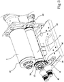
- the front adjustment device 15 comprises a front drive system 38, visible for example in figure 3 , for rotating the front eccentric element 17 about the longitudinal axis A2.
- the front drive system 38 comprises a toothed crown 39, arranged in a fixed position with respect to the front eccentric element 17.
- the toothed crown 39 extends about the longitudinal axis A2, i.e. it is coaxial with the seating 24 of the front eccentric element 17 and with the counter roller 6.
- the front drive system 38 further comprises a toothed pinion 40, configured for enmeshing with the toothed crown 39 and rotatable about a parallel axis to the longitudinal axis A2.
- the toothed crown 39 is correspondingly rotated about the longitudinal axis A2, and consequently the angular position of the front eccentric element 17 is modified about the longitudinal axis A2. This enables varying the position of the main axis A1 in a frontal region of the cutting apparatus 1.
- the toothed pinion 40 is mounted on a drive shaft 41 connected to a front control element 42, conformed for example as a knob, activatable by the operator to rotate the drive shaft 41 about the axis thereof, so as to regulate the angular position of the front eccentric element 17.
- the drive shaft 41 is provided with a prolongation 43 which extends up to a rear region of the cutting apparatus 1 and is connected to an encoder 44, which enables detecting the angular position of the drive shaft 41. In this way it is possible to know, at any moment, the angular position of the toothed pinion 40 and, consequently, the angular position of the toothed crown 39 and the front eccentric element 17.
- the rear adjustment device 16 comprises a rear drive system 45, visible for example in figure 4 , for rotating the rear eccentric element 27 about the longitudinal axis A2.
- the rear drive system 45 is entirely alike the front drive system 38.
- the rear drive system 45 comprises a toothed wheel 46, mounted in a fixed position with respect to the rear eccentric element 27 and therefore rotatable solidly with the rear eccentric element 27 about the longitudinal axis A2.
- the toothed wheel 46 is coaxial with the hole 34 internally of which the rear shank 29 of the counter roller 6 is mounted. The toothed wheel 46 is therefore coaxial with the counter roller 6.
- the rear drive system 45 further comprises a drive pinion 47, configured for enmeshing with the toothed wheel 46 so as to rotate the toothed crown about the longitudinal axis A2.
- the drive pinion 47 is rotatable about a parallel axis to the longitudinal axis A2.
- the drive pinion 47 is mounted on a drive rod 48 connected to a rear control element 49, conformed for example as a knob, activatable by the operator to rotate the drive rod 48 about the axis thereof, so as to regulate the angular position of the rear eccentric element 27.
- the drive pinion 47 is rotated which by enmeshing with the toothed wheel 46, rotates the toothed wheel 46 about the longitudinal axis A2. In this way the angular position of the rear eccentric element 27 about the longitudinal axis A2 is modified.
- the rear eccentric element 27 in turn displaces the rear annular element 30, which causes a variation in the position of the main axis A1 relative to the longitudinal axis A2.
- a further encoder 50 which enables detecting the angular position of the drive rod 48, is mounted to a rear end of the drive rod 48, i.e. to an end of the drive rod 48 opposite the end at which the rear control element 49 is arranged. In this way it is possible to know, at any moment, the angular position of the drive pinion 47 and, consequently, the angular position of the toothed wheel 46 and the rear eccentric element 30.
- the cutting apparatus 1 further comprises a pressing device for pressing the cutting roller 5 and the counter roller 6 one against the other, in particular to push the cutting roller 5 towards the counter roller 6.
- a pressing device for pressing the cutting roller 5 and the counter roller 6 one against the other, in particular to push the cutting roller 5 towards the counter roller 6.
- the pressing device acts on the annular elements 20, 30 associated to the cutting roller 5, so as to push the annular elements 20, 30 towards the corresponding eccentric elements 17, 27.
- the pressing device acts on the cutting roller 5 via the annular elements 20, 30.
- the pressing device comprises a front pressing device 51, arranged so as to act on a region of front end of the cutting roller 5, and a rear pressing device 52, arranged so as to act on a rear end region of the cutting roller 5.
- the front pressing device 51 comprises a pair of front presser elements 53, in particular conformed as wheels, which are arranged in contact with the front annular element 20.
- the front presser elements 53 are in particular in contact with an upper portion of the front annular element 20, i.e with a portion of the front annular element 20 further from the counter roller 6.
- the front presser elements 53 are arranged in a symmetrical position with respect to a vertical plane containing the main axis A1.
- the rear pressing device 52 comprises a pair of rear presser elements 63 conformed in particular as wheels, which are arranged in contact with an upper portion of the rear annular element 30.
- the rear presser elements 63 are also arranged symmetrically with respect to a vertical plane containing the main axis A1.
- the front presser elements 53 are supported by a front support element 54, arranged in proximity of the front end of the cutting roller 5.
- the rear presser elements 63 are supported by a rear support element 64, arranged in proximity of the rear end of the cutting roller 5.
- Both the front support element 54 and the rear support element 64 can be conformed as a bridge element, i.e. as an overturned U-shaped plate.
- the front support element 54 and the rear support element 64 are connected to a base 55 of the cutting apparatus 1, the base 55 being in particular destined to be positioned horizontally during the operation of the cutting apparatus 1.
- the base 55 is arranged below the cutting roller 5 and the counter roller 6.
- front support element 54 and the rear support element 64 can be connected to the base 55 in such a way that the position thereof is adjustable in height with respect to the base 55.
- the front support element 54 and the rear support element 64 are pneumatically activatable for varying the pressure acting on the annular elements 20, 30 associated to the cutting roller 5.
- two pneumatic cylinders 56 are included, visible for example in figure 5 , which can be supported by the base 55, in particular housed internally of corresponding seatings fashioned in the base 55.
- the pneumatic cylinders 56 are arranged on opposite sides of the main axis A1 and of the longitudinal axis A2, in an intermediate position between the front support element 54 and the rear support element 64.
- Each pneumatic cylinder 56 is connected to an intermediate region of a corresponding rocker arm 57, so that the rocker arm 57 can oscillate with respect to the respective cylinder.
- each cylinder 56 is provided with a rod fixed to an eyelet 58, internally of which a pin fixed to the rocker arm 57 is fixed.
- Each rocker arm 57 extends along a direction that is substantially parallel to the main axis A1 and to the longitudinal axis A2.
- Each rocker arm 57 has an end connected to the front support element 54 and a further end, opposite the above-mentioned end, connected to the rear support element 64.
- the connection between the ends of the rocker arm 57 and the support elements 54, 64 is such as to enable the ends of the rocker arm 57 to oscillate with respect to the support element 54, 64.
- this corresponds to applying - by means of the pneumatic fluid sent into the pneumatic cylinders 56 - a force that tends to cause the rods of the pneumatic cylinders 56 to retract towards the inside of the cylinders.
- the support elements 54, 64 are thus pushed towards the base 55. Consequently, the presser elements 53, 63 supported by the support elements 54, 64 are pressed against the annular elements 20, 30. In this way the strip material 14 passing through the slot 37 is prevented from distancing the cutting roller 5 from the counter roller 6.
- the position adjustment device by means of which it is possible to adjust the relative position of the cutting roller 5 and the counter roller 6, is distinct and independent from the pressing device, by means of which the cutting roller 5 is pushed towards the counter roller 6. In this way, it is possible - in an initial step - to correctly position the cutting roller 5 with respect to the counter roller 6, by acting on the front adjustment device 15 and on the rear adjustment device 16. This can be done simply and reliably owing to the eccentric elements 17, 27.
- the thickness S1 of the support layer 10 and the thickness S2 of the cutting die 7 it is possible to determine the height H theoretically required for the slot 37. This corresponds to a predetermined angular position of the eccentric elements 17, 27 which can be easily calculated, as the geometry of the system is of known type, as is also the current angular position of the eccentric elements 17, 27 (thanks to the encoder 44 and the further encoder 50). The eccentric elements 17, 27 are now positioned in the angular position calculated.
- the pressing device does not however vary the relative position of the main axis A1 and the longitudinal axis A2.
- the cutting apparatus 1 is now ready to function.
- the position adjustment device can be used also while the cutting apparatus 1 is operating. If it is found that the labels are cut in an incorrect way, for example because the cutting die 7 is becoming worn, it is possible to act on the eccentric elements 17, 27 so as to regulate the distance between the main axis A1 and the longitudinal axis A2, or the inclination of the main axis A1 with respect to the longitudinal axis A2, without stopping the cutting apparatus 1. This enables maintaining a good cut quality, without there being any loss of productivity due to halts of the cutting apparatus 1.
Landscapes
- Life Sciences & Earth Sciences (AREA)
- Forests & Forestry (AREA)
- Engineering & Computer Science (AREA)
- Mechanical Engineering (AREA)
- Perforating, Stamping-Out Or Severing By Means Other Than Cutting (AREA)
Priority Applications (1)
| Application Number | Priority Date | Filing Date | Title |
|---|---|---|---|
| PL16190570T PL3150367T3 (pl) | 2015-09-28 | 2016-09-26 | Urządzenie do obróbki elastycznego materiału |
Applications Claiming Priority (1)
| Application Number | Priority Date | Filing Date | Title |
|---|---|---|---|
| ITUB2015A003933A ITUB20153933A1 (it) | 2015-09-28 | 2015-09-28 | Apparato per processare un materiale flessibile. |
Publications (2)
| Publication Number | Publication Date |
|---|---|
| EP3150367A1 EP3150367A1 (en) | 2017-04-05 |
| EP3150367B1 true EP3150367B1 (en) | 2019-12-25 |
Family
ID=55070041
Family Applications (1)
| Application Number | Title | Priority Date | Filing Date |
|---|---|---|---|
| EP16190570.8A Active EP3150367B1 (en) | 2015-09-28 | 2016-09-26 | Apparatus for processing a flexible material |
Country Status (8)
| Country | Link |
|---|---|
| US (1) | US10179422B2 (da) |
| EP (1) | EP3150367B1 (da) |
| DK (1) | DK3150367T3 (da) |
| ES (1) | ES2774096T3 (da) |
| HU (1) | HUE048992T2 (da) |
| IT (1) | ITUB20153933A1 (da) |
| PL (1) | PL3150367T3 (da) |
| PT (1) | PT3150367T (da) |
Families Citing this family (6)
| Publication number | Priority date | Publication date | Assignee | Title |
|---|---|---|---|---|
| CN108818679A (zh) * | 2018-06-19 | 2018-11-16 | 东莞市联洲知识产权运营管理有限公司 | 一种钢纸生产用的剪裁装置 |
| US10857690B2 (en) * | 2018-09-11 | 2020-12-08 | The Procter & Gamble Company | Method and apparatus for adjusting and maintaining a position of a cutting surface of a perforating apparatus |
| DE102019122509A1 (de) * | 2019-08-21 | 2021-02-25 | Kolbus Gmbh & Co. Kg | Vorrichtung zur Herstellung von Buchdecken, Schachteldecken oder Spielebrettern |
| CN111195990B (zh) * | 2020-02-25 | 2024-11-15 | 青岛高测科技股份有限公司 | 一种调整切片机切割区线网中心距的装置及调整方法 |
| US11618177B1 (en) | 2022-04-12 | 2023-04-04 | Bradley W Boesel | Orbital knife |
| PL445998A1 (pl) | 2023-09-04 | 2025-03-10 | Grafotronic Spółka Z Ograniczoną Odpowiedzialnością | Urządzenie i sposób do obrabiania etykiet |
Family Cites Families (24)
| Publication number | Priority date | Publication date | Assignee | Title |
|---|---|---|---|---|
| US4063493A (en) * | 1976-11-15 | 1977-12-20 | H&H Industries, Inc. | Rotary die cutting machine |
| FR2595610A1 (fr) * | 1986-03-13 | 1987-09-18 | Gautier Jean | Dispositif de decoupe rotative ou de refoulage pour produits plats |
| US5048387A (en) * | 1989-07-14 | 1991-09-17 | Komori Corporation | Horizontal perforation forming apparatus for rotary press |
| DE3924053A1 (de) * | 1989-07-21 | 1991-01-24 | Wilhelm Aichele | Vorrichtung zum rotationsschneiden von werkstoffbahnen |
| AU7859491A (en) * | 1990-05-10 | 1991-11-27 | Byron L. Buck | Rotary die cutting system for sheet material |
| US5083488A (en) * | 1991-04-12 | 1992-01-28 | Melvin Stanley | Radially adjustable anvil roll assembly for a rotary die cutting press |
| US5156076A (en) * | 1991-05-21 | 1992-10-20 | Rosemann Richard R | Radially adjustable anvil roll assembly for a rotary die cutting press |
| US5598758A (en) * | 1993-07-22 | 1997-02-04 | Moore Business Forms, Inc. | Quick change cassette hole punch unit |
| DE19736762C2 (de) * | 1997-08-23 | 2000-05-25 | Kocher & Beck Gmbh & Co Rotati | Vorrichtung zum Stanzen, insbesondere von Etiketten |
| US6389941B1 (en) * | 2000-04-14 | 2002-05-21 | Marquip, Llc | Rotary knife with electromagnetic active vibration control |
| NL1024915C2 (nl) * | 2003-12-01 | 2005-06-06 | Jean Henry Robert Madern | Inrichting voor het aanbrengen van een snede, ril en dergelijke, omvattende een plaatvormig stelsel. |
| SE527556C2 (sv) * | 2004-07-02 | 2006-04-11 | Sandvik Intellectual Property | En stödvals för en rotationsknivenhet och en rotationsknivenhet med en dylik stödvals |
| DE102004050443B4 (de) * | 2004-10-16 | 2006-11-23 | Electro Optic Werkzeugtechnik Gmbh | Vorrichtung zum Rotationsstanzen, Umrüstsatz für eine Vorrichtung zum Rotationsstanzen und Verfahren zum Umrüsten |
| DE102005022604A1 (de) * | 2005-05-11 | 2006-11-16 | Aichele Werkzeuge Gmbh | Rotationsschneidvorrichtung, Verfahren zur Außerbetriebnahme einer Rotationsschneidvorrichtung und Verfahren zum Betrieb einer Rotationsschneidvorrichtung |
| US20070101844A1 (en) * | 2005-11-10 | 2007-05-10 | Spilker Gmbh | Punching device |
| IT1394271B1 (it) * | 2009-05-25 | 2012-06-06 | Ima Flavour S R L Ora Ima Ind S R L | Gruppo di compressione - incisione - taglio a rulli |
| JP5590899B2 (ja) * | 2010-02-01 | 2014-09-17 | ユニ・チャーム株式会社 | ロータリ加工装置 |
| EP2534709B1 (en) * | 2010-02-08 | 2015-01-14 | Sca Hygiene Products AB | Apparatus and method for treating products |
| US9902083B2 (en) * | 2010-09-30 | 2018-02-27 | The Procter & Gamble Company | Absorbent article substrate trim material removal process and apparatus |
| SE536109C2 (sv) * | 2011-04-08 | 2013-05-07 | Sandvik Intellectual Property | Roterande skärande apparatur med vibrationsdämpningsmedel |
| DE102011108505A1 (de) * | 2011-07-25 | 2013-01-31 | Gallus Druckmaschinen Gmbh | Vorrichtung zum Stanzen mit einstellbarem Zylinderabstand |
| ES2570180T3 (es) * | 2012-04-27 | 2016-05-17 | Sandvik Intellectual Property | Unidad de corte que comprende un armazón estacionario, un tambor de corte y un tambor de yunque |
| US8869690B2 (en) * | 2012-09-07 | 2014-10-28 | Ming-Cheng Wang | Stationery machine |
| DE102013208909A1 (de) * | 2013-05-14 | 2014-11-20 | Kocher + Beck Gmbh + Co. Rotationsstanztechnik Kg | Verfahren und Vorrichtung zum Stanzen |
-
2015
- 2015-09-28 IT ITUB2015A003933A patent/ITUB20153933A1/it unknown
-
2016
- 2016-09-26 PT PT161905708T patent/PT3150367T/pt unknown
- 2016-09-26 EP EP16190570.8A patent/EP3150367B1/en active Active
- 2016-09-26 PL PL16190570T patent/PL3150367T3/pl unknown
- 2016-09-26 DK DK16190570.8T patent/DK3150367T3/da active
- 2016-09-26 HU HUE16190570A patent/HUE048992T2/hu unknown
- 2016-09-26 ES ES16190570T patent/ES2774096T3/es active Active
- 2016-09-27 US US15/277,320 patent/US10179422B2/en active Active
Non-Patent Citations (1)
| Title |
|---|
| None * |
Also Published As
| Publication number | Publication date |
|---|---|
| US10179422B2 (en) | 2019-01-15 |
| PL3150367T3 (pl) | 2020-06-01 |
| EP3150367A1 (en) | 2017-04-05 |
| ES2774096T3 (es) | 2020-07-16 |
| PT3150367T (pt) | 2020-03-27 |
| ITUB20153933A1 (it) | 2017-03-28 |
| US20170087737A1 (en) | 2017-03-30 |
| DK3150367T3 (da) | 2020-03-16 |
| HUE048992T2 (hu) | 2020-09-28 |
Similar Documents
| Publication | Publication Date | Title |
|---|---|---|
| EP3150367B1 (en) | Apparatus for processing a flexible material | |
| US4130042A (en) | Adjustable anvil roll for die-cutting labels | |
| BRPI0715576A2 (pt) | mecanismo de corte para uma unidade etiquetadora assim como unidade etiquetadpra com um tal mecanismo de corte | |
| US5022295A (en) | Method and apparatus for maintaining the cutting conditions of a rotary punch constant | |
| EP0421782A2 (en) | Shearing machine | |
| EP1844926A2 (en) | Logo embossing assembly for products such as tissues, napkins and the like | |
| US4528831A (en) | Wire coiling machine | |
| JP7582931B2 (ja) | 切込方法及び切込装置 | |
| GB2128514A (en) | Wire coiling machine | |
| US12157245B2 (en) | Apparatus for cutting caps | |
| EP1703811B1 (en) | Cutting unit for cutting continuous cigarette rods | |
| CN203974208U (zh) | 一种拉纸分切机 | |
| CN204414224U (zh) | 圆模切机分切机构 | |
| CA3147984A1 (en) | Cutting machine with blade depth adjustment | |
| EP3842197B1 (en) | Device and method for cutting cord-embedded rubber sheet member | |
| GB2181984A (en) | Cutting material into reels | |
| CN204075364U (zh) | 一种棒材截料机的刀具调节装置 | |
| CN218398502U (zh) | 一种裁断机裁断机构 | |
| US1667184A (en) | Cutting machine | |
| CN214102968U (zh) | 一种面条切丝刀 | |
| US2062990A (en) | Cigarette cut-off device | |
| JPS6032395B2 (ja) | スピ−カ−用コ−ン紙の切断装置 | |
| US91380A (en) | Improvement in saw-q-ttmmer | |
| US2770300A (en) | Method of and apparatus for forming serrated cutting edges on slicer blades | |
| US707778A (en) | Tobacco-cutting machine. |
Legal Events
| Date | Code | Title | Description |
|---|---|---|---|
| PUAI | Public reference made under article 153(3) epc to a published international application that has entered the european phase |
Free format text: ORIGINAL CODE: 0009012 |
|
| STAA | Information on the status of an ep patent application or granted ep patent |
Free format text: STATUS: THE APPLICATION HAS BEEN PUBLISHED |
|
| AK | Designated contracting states |
Kind code of ref document: A1 Designated state(s): AL AT BE BG CH CY CZ DE DK EE ES FI FR GB GR HR HU IE IS IT LI LT LU LV MC MK MT NL NO PL PT RO RS SE SI SK SM TR |
|
| AX | Request for extension of the european patent |
Extension state: BA ME |
|
| STAA | Information on the status of an ep patent application or granted ep patent |
Free format text: STATUS: REQUEST FOR EXAMINATION WAS MADE |
|
| 17P | Request for examination filed |
Effective date: 20170620 |
|
| RBV | Designated contracting states (corrected) |
Designated state(s): AL AT BE BG CH CY CZ DE DK EE ES FI FR GB GR HR HU IE IS IT LI LT LU LV MC MK MT NL NO PL PT RO RS SE SI SK SM TR |
|
| REG | Reference to a national code |
Ref country code: DE Ref legal event code: R079 Ref document number: 602016026733 Country of ref document: DE Free format text: PREVIOUS MAIN CLASS: B31D0001020000 Ipc: B26F0001380000 |
|
| GRAP | Despatch of communication of intention to grant a patent |
Free format text: ORIGINAL CODE: EPIDOSNIGR1 |
|
| STAA | Information on the status of an ep patent application or granted ep patent |
Free format text: STATUS: GRANT OF PATENT IS INTENDED |
|
| RIC1 | Information provided on ipc code assigned before grant |
Ipc: B26F 1/38 20060101AFI20190828BHEP Ipc: B26D 7/00 20060101ALN20190828BHEP Ipc: B26D 1/40 20060101ALN20190828BHEP |
|
| INTG | Intention to grant announced |
Effective date: 20190913 |
|
| GRAS | Grant fee paid |
Free format text: ORIGINAL CODE: EPIDOSNIGR3 |
|
| GRAA | (expected) grant |
Free format text: ORIGINAL CODE: 0009210 |
|
| STAA | Information on the status of an ep patent application or granted ep patent |
Free format text: STATUS: THE PATENT HAS BEEN GRANTED |
|
| AK | Designated contracting states |
Kind code of ref document: B1 Designated state(s): AL AT BE BG CH CY CZ DE DK EE ES FI FR GB GR HR HU IE IS IT LI LT LU LV MC MK MT NL NO PL PT RO RS SE SI SK SM TR |
|
| REG | Reference to a national code |
Ref country code: GB Ref legal event code: FG4D |
|
| REG | Reference to a national code |
Ref country code: CH Ref legal event code: EP |
|
| REG | Reference to a national code |
Ref country code: DE Ref legal event code: R096 Ref document number: 602016026733 Country of ref document: DE |
|
| REG | Reference to a national code |
Ref country code: AT Ref legal event code: REF Ref document number: 1216663 Country of ref document: AT Kind code of ref document: T Effective date: 20200115 |
|
| REG | Reference to a national code |
Ref country code: IE Ref legal event code: FG4D |
|
| REG | Reference to a national code |
Ref country code: CH Ref legal event code: NV Representative=s name: BUGNION S.A., CH |
|
| REG | Reference to a national code |
Ref country code: DK Ref legal event code: T3 Effective date: 20200312 |
|
| REG | Reference to a national code |
Ref country code: RO Ref legal event code: EPE |
|
| REG | Reference to a national code |
Ref country code: PT Ref legal event code: SC4A Ref document number: 3150367 Country of ref document: PT Date of ref document: 20200327 Kind code of ref document: T Free format text: AVAILABILITY OF NATIONAL TRANSLATION Effective date: 20200318 |
|
| REG | Reference to a national code |
Ref country code: NL Ref legal event code: FP |
|
| REG | Reference to a national code |
Ref country code: SE Ref legal event code: TRGR |
|
| PG25 | Lapsed in a contracting state [announced via postgrant information from national office to epo] |
Ref country code: LT Free format text: LAPSE BECAUSE OF FAILURE TO SUBMIT A TRANSLATION OF THE DESCRIPTION OR TO PAY THE FEE WITHIN THE PRESCRIBED TIME-LIMIT Effective date: 20191225 Ref country code: LV Free format text: LAPSE BECAUSE OF FAILURE TO SUBMIT A TRANSLATION OF THE DESCRIPTION OR TO PAY THE FEE WITHIN THE PRESCRIBED TIME-LIMIT Effective date: 20191225 Ref country code: FI Free format text: LAPSE BECAUSE OF FAILURE TO SUBMIT A TRANSLATION OF THE DESCRIPTION OR TO PAY THE FEE WITHIN THE PRESCRIBED TIME-LIMIT Effective date: 20191225 Ref country code: NO Free format text: LAPSE BECAUSE OF FAILURE TO SUBMIT A TRANSLATION OF THE DESCRIPTION OR TO PAY THE FEE WITHIN THE PRESCRIBED TIME-LIMIT Effective date: 20200325 Ref country code: GR Free format text: LAPSE BECAUSE OF FAILURE TO SUBMIT A TRANSLATION OF THE DESCRIPTION OR TO PAY THE FEE WITHIN THE PRESCRIBED TIME-LIMIT Effective date: 20200326 |
|
| REG | Reference to a national code |
Ref country code: LT Ref legal event code: MG4D |
|
| PG25 | Lapsed in a contracting state [announced via postgrant information from national office to epo] |
Ref country code: RS Free format text: LAPSE BECAUSE OF FAILURE TO SUBMIT A TRANSLATION OF THE DESCRIPTION OR TO PAY THE FEE WITHIN THE PRESCRIBED TIME-LIMIT Effective date: 20191225 Ref country code: HR Free format text: LAPSE BECAUSE OF FAILURE TO SUBMIT A TRANSLATION OF THE DESCRIPTION OR TO PAY THE FEE WITHIN THE PRESCRIBED TIME-LIMIT Effective date: 20191225 |
|
| REG | Reference to a national code |
Ref country code: SK Ref legal event code: T3 Ref document number: E 33787 Country of ref document: SK |
|
| PG25 | Lapsed in a contracting state [announced via postgrant information from national office to epo] |
Ref country code: AL Free format text: LAPSE BECAUSE OF FAILURE TO SUBMIT A TRANSLATION OF THE DESCRIPTION OR TO PAY THE FEE WITHIN THE PRESCRIBED TIME-LIMIT Effective date: 20191225 |
|
| REG | Reference to a national code |
Ref country code: ES Ref legal event code: FG2A Ref document number: 2774096 Country of ref document: ES Kind code of ref document: T3 Effective date: 20200716 |
|
| PG25 | Lapsed in a contracting state [announced via postgrant information from national office to epo] |
Ref country code: EE Free format text: LAPSE BECAUSE OF FAILURE TO SUBMIT A TRANSLATION OF THE DESCRIPTION OR TO PAY THE FEE WITHIN THE PRESCRIBED TIME-LIMIT Effective date: 20191225 |
|
| PG25 | Lapsed in a contracting state [announced via postgrant information from national office to epo] |
Ref country code: IS Free format text: LAPSE BECAUSE OF FAILURE TO SUBMIT A TRANSLATION OF THE DESCRIPTION OR TO PAY THE FEE WITHIN THE PRESCRIBED TIME-LIMIT Effective date: 20200425 Ref country code: SM Free format text: LAPSE BECAUSE OF FAILURE TO SUBMIT A TRANSLATION OF THE DESCRIPTION OR TO PAY THE FEE WITHIN THE PRESCRIBED TIME-LIMIT Effective date: 20191225 |
|
| REG | Reference to a national code |
Ref country code: HU Ref legal event code: AG4A Ref document number: E048992 Country of ref document: HU Ref country code: DE Ref legal event code: R097 Ref document number: 602016026733 Country of ref document: DE |
|
| PLBE | No opposition filed within time limit |
Free format text: ORIGINAL CODE: 0009261 |
|
| STAA | Information on the status of an ep patent application or granted ep patent |
Free format text: STATUS: NO OPPOSITION FILED WITHIN TIME LIMIT |
|
| PG25 | Lapsed in a contracting state [announced via postgrant information from national office to epo] |
Ref country code: SI Free format text: LAPSE BECAUSE OF FAILURE TO SUBMIT A TRANSLATION OF THE DESCRIPTION OR TO PAY THE FEE WITHIN THE PRESCRIBED TIME-LIMIT Effective date: 20191225 |
|
| 26N | No opposition filed |
Effective date: 20200928 |
|
| PG25 | Lapsed in a contracting state [announced via postgrant information from national office to epo] |
Ref country code: MC Free format text: LAPSE BECAUSE OF FAILURE TO SUBMIT A TRANSLATION OF THE DESCRIPTION OR TO PAY THE FEE WITHIN THE PRESCRIBED TIME-LIMIT Effective date: 20191225 |
|
| PG25 | Lapsed in a contracting state [announced via postgrant information from national office to epo] |
Ref country code: LU Free format text: LAPSE BECAUSE OF NON-PAYMENT OF DUE FEES Effective date: 20200926 |
|
| REG | Reference to a national code |
Ref country code: AT Ref legal event code: UEP Ref document number: 1216663 Country of ref document: AT Kind code of ref document: T Effective date: 20191225 |
|
| PG25 | Lapsed in a contracting state [announced via postgrant information from national office to epo] |
Ref country code: MT Free format text: LAPSE BECAUSE OF FAILURE TO SUBMIT A TRANSLATION OF THE DESCRIPTION OR TO PAY THE FEE WITHIN THE PRESCRIBED TIME-LIMIT Effective date: 20191225 Ref country code: CY Free format text: LAPSE BECAUSE OF FAILURE TO SUBMIT A TRANSLATION OF THE DESCRIPTION OR TO PAY THE FEE WITHIN THE PRESCRIBED TIME-LIMIT Effective date: 20191225 |
|
| PG25 | Lapsed in a contracting state [announced via postgrant information from national office to epo] |
Ref country code: MK Free format text: LAPSE BECAUSE OF FAILURE TO SUBMIT A TRANSLATION OF THE DESCRIPTION OR TO PAY THE FEE WITHIN THE PRESCRIBED TIME-LIMIT Effective date: 20191225 |
|
| P01 | Opt-out of the competence of the unified patent court (upc) registered |
Effective date: 20230703 |
|
| PGFP | Annual fee paid to national office [announced via postgrant information from national office to epo] |
Ref country code: TR Payment date: 20230919 Year of fee payment: 8 Ref country code: RO Payment date: 20230925 Year of fee payment: 8 Ref country code: NL Payment date: 20230926 Year of fee payment: 8 Ref country code: IE Payment date: 20230926 Year of fee payment: 8 Ref country code: CZ Payment date: 20230922 Year of fee payment: 8 Ref country code: BG Payment date: 20230925 Year of fee payment: 8 Ref country code: AT Payment date: 20230926 Year of fee payment: 8 |
|
| PGFP | Annual fee paid to national office [announced via postgrant information from national office to epo] |
Ref country code: SK Payment date: 20230925 Year of fee payment: 8 Ref country code: PT Payment date: 20230918 Year of fee payment: 8 Ref country code: HU Payment date: 20230921 Year of fee payment: 8 Ref country code: FR Payment date: 20230926 Year of fee payment: 8 Ref country code: DK Payment date: 20230927 Year of fee payment: 8 Ref country code: BE Payment date: 20230926 Year of fee payment: 8 |
|
| PGFP | Annual fee paid to national office [announced via postgrant information from national office to epo] |
Ref country code: ES Payment date: 20231017 Year of fee payment: 8 |
|
| PGFP | Annual fee paid to national office [announced via postgrant information from national office to epo] |
Ref country code: CH Payment date: 20231001 Year of fee payment: 8 |
|
| PG25 | Lapsed in a contracting state [announced via postgrant information from national office to epo] |
Ref country code: PT Free format text: LAPSE BECAUSE OF NON-PAYMENT OF DUE FEES Effective date: 20250326 |
|
| PG25 | Lapsed in a contracting state [announced via postgrant information from national office to epo] |
Ref country code: BG Free format text: LAPSE BECAUSE OF NON-PAYMENT OF DUE FEES Effective date: 20240926 |
|
| REG | Reference to a national code |
Ref country code: DK Ref legal event code: EBP Effective date: 20240930 |
|
| PG25 | Lapsed in a contracting state [announced via postgrant information from national office to epo] |
Ref country code: CZ Free format text: LAPSE BECAUSE OF NON-PAYMENT OF DUE FEES Effective date: 20240926 |
|
| REG | Reference to a national code |
Ref country code: CH Ref legal event code: PL |
|
| REG | Reference to a national code |
Ref country code: NL Ref legal event code: MM Effective date: 20241001 Ref country code: SK Ref legal event code: MM4A Ref document number: E 33787 Country of ref document: SK Effective date: 20240926 |
|
| REG | Reference to a national code |
Ref country code: AT Ref legal event code: MM01 Ref document number: 1216663 Country of ref document: AT Kind code of ref document: T Effective date: 20240926 |
|
| PG25 | Lapsed in a contracting state [announced via postgrant information from national office to epo] |
Ref country code: NL Free format text: LAPSE BECAUSE OF NON-PAYMENT OF DUE FEES Effective date: 20241001 |
|
| REG | Reference to a national code |
Ref country code: BE Ref legal event code: MM Effective date: 20240930 |
|
| PG25 | Lapsed in a contracting state [announced via postgrant information from national office to epo] |
Ref country code: HU Free format text: LAPSE BECAUSE OF NON-PAYMENT OF DUE FEES Effective date: 20240927 |
|
| PG25 | Lapsed in a contracting state [announced via postgrant information from national office to epo] |
Ref country code: BE Free format text: LAPSE BECAUSE OF NON-PAYMENT OF DUE FEES Effective date: 20240930 |
|
| PG25 | Lapsed in a contracting state [announced via postgrant information from national office to epo] |
Ref country code: FR Free format text: LAPSE BECAUSE OF NON-PAYMENT OF DUE FEES Effective date: 20240930 |
|
| PG25 | Lapsed in a contracting state [announced via postgrant information from national office to epo] |
Ref country code: CH Free format text: LAPSE BECAUSE OF NON-PAYMENT OF DUE FEES Effective date: 20240930 |
|
| PG25 | Lapsed in a contracting state [announced via postgrant information from national office to epo] |
Ref country code: AT Free format text: LAPSE BECAUSE OF NON-PAYMENT OF DUE FEES Effective date: 20240926 Ref country code: RO Free format text: LAPSE BECAUSE OF NON-PAYMENT OF DUE FEES Effective date: 20240926 |
|
| PG25 | Lapsed in a contracting state [announced via postgrant information from national office to epo] |
Ref country code: SK Free format text: LAPSE BECAUSE OF NON-PAYMENT OF DUE FEES Effective date: 20240926 |
|
| PG25 | Lapsed in a contracting state [announced via postgrant information from national office to epo] |
Ref country code: IE Free format text: LAPSE BECAUSE OF NON-PAYMENT OF DUE FEES Effective date: 20240926 |
|
| PG25 | Lapsed in a contracting state [announced via postgrant information from national office to epo] |
Ref country code: DK Free format text: LAPSE BECAUSE OF NON-PAYMENT OF DUE FEES Effective date: 20240930 |
|
| PGFP | Annual fee paid to national office [announced via postgrant information from national office to epo] |
Ref country code: DE Payment date: 20250926 Year of fee payment: 10 |
|
| PGFP | Annual fee paid to national office [announced via postgrant information from national office to epo] |
Ref country code: PL Payment date: 20250915 Year of fee payment: 10 Ref country code: IT Payment date: 20250923 Year of fee payment: 10 |
|
| PGFP | Annual fee paid to national office [announced via postgrant information from national office to epo] |
Ref country code: GB Payment date: 20250923 Year of fee payment: 10 |
|
| PGFP | Annual fee paid to national office [announced via postgrant information from national office to epo] |
Ref country code: SE Payment date: 20250924 Year of fee payment: 10 |
|
| REG | Reference to a national code |
Ref country code: ES Ref legal event code: FD2A Effective date: 20251103 |
|
| PG25 | Lapsed in a contracting state [announced via postgrant information from national office to epo] |
Ref country code: ES Free format text: LAPSE BECAUSE OF NON-PAYMENT OF DUE FEES Effective date: 20240927 |