EP3153263B1 - Nutenfrässcheibe und nutenfräser mit einer solchen nutenfrässcheibe - Google Patents
Nutenfrässcheibe und nutenfräser mit einer solchen nutenfrässcheibe Download PDFInfo
- Publication number
- EP3153263B1 EP3153263B1 EP15189072.0A EP15189072A EP3153263B1 EP 3153263 B1 EP3153263 B1 EP 3153263B1 EP 15189072 A EP15189072 A EP 15189072A EP 3153263 B1 EP3153263 B1 EP 3153263B1
- Authority
- EP
- European Patent Office
- Prior art keywords
- slot milling
- disc
- channel portion
- milling disc
- slot
- Prior art date
- Legal status (The legal status is an assumption and is not a legal conclusion. Google has not performed a legal analysis and makes no representation as to the accuracy of the status listed.)
- Not-in-force
Links
Images


Classifications
-
- B—PERFORMING OPERATIONS; TRANSPORTING
- B23—MACHINE TOOLS; METAL-WORKING NOT OTHERWISE PROVIDED FOR
- B23C—MILLING
- B23C5/00—Milling-cutters
- B23C5/02—Milling-cutters characterised by the shape of the cutter
- B23C5/08—Disc-type cutters
-
- B—PERFORMING OPERATIONS; TRANSPORTING
- B23—MACHINE TOOLS; METAL-WORKING NOT OTHERWISE PROVIDED FOR
- B23C—MILLING
- B23C5/00—Milling-cutters
- B23C5/26—Securing milling cutters to the driving spindle
-
- B—PERFORMING OPERATIONS; TRANSPORTING
- B23—MACHINE TOOLS; METAL-WORKING NOT OTHERWISE PROVIDED FOR
- B23C—MILLING
- B23C5/00—Milling-cutters
- B23C5/28—Features relating to lubricating or cooling
-
- B—PERFORMING OPERATIONS; TRANSPORTING
- B23—MACHINE TOOLS; METAL-WORKING NOT OTHERWISE PROVIDED FOR
- B23C—MILLING
- B23C2210/00—Details of milling cutters
- B23C2210/16—Fixation of inserts or cutting bits in the tool
- B23C2210/161—Elastically deformable clamping members
-
- B—PERFORMING OPERATIONS; TRANSPORTING
- B23—MACHINE TOOLS; METAL-WORKING NOT OTHERWISE PROVIDED FOR
- B23C—MILLING
- B23C2260/00—Details of constructional elements
- B23C2260/72—Seals
Definitions
- the present invention relates to a slot milling disc according to the preamble of appended claim 1 and a slot milling tool comprising such a slot milling disc.
- slot milling disc An example of a slot milling disc according to the preamble of claim 1 is known from JP H06 31579 A1 .
- "Means configured to allow rotary preventing attachment of the slot milling disc to a rotatable mounting shaft” is to be interpreted to cover means making it possible to attach the slot milling disc to a rotatable mounting shaft, such as by for instance tightening of screws, as well as means creating a permanent attachment of the disc to a rotatable mounting shaft, such as obtained by welding or by making the slot milling disc and the mounting shaft in one single piece.
- a flushing fluid in the form of a gas or a liquid or a mixture of gas and liquid.
- Such flushing can be performed for different reasons, e.g. for cooling or lubricating purpose or for washing away cuttings or chips from the work piece during machining.
- the present invention is mainly but not solely directed to the problem of washing away cuttings or chips from the work piece during machining, which is particularly delicate when creating narrow slots, i.e. slots with a small width, by a slot milling disc.
- a common way to achieve flushing of a slot milling disc is to simply direct a stream of liquid and/or gas from the outside towards the milling disc and the work piece at an area where the actual machining takes place. Flushing of such milling discs with a flushing fluid for purpose of cooling, lubricating and/or flushing away chips, performed by means of one or more flushing fluid jets directed towards the milling disc and the work piece from the outside is ineffective, in particular in deep slotting and for flushing away cuttings or chips, because the outside jet in general cannot reach the relative deep parts of such narrow slots during the slot or groove milling operation. Hence, the flushing will be very ineffective as most of the fluid will not reach the area where it could be of use. In case of a liquid flushing medium this will also result in a formation of a large amount of waste liquid, which has to be collected and filtered or disposed of.
- DE 10145006 discloses a slot milling disc comprising an integrated disc-shaped portion and a hub-formed portion, which is arranged at the centre of the disc-shaped portion and which is adapted to be connected to a rotatable shaft at a bearing surface having a recess or spline at the rear end of the hub portion.
- the disc has coolant channels having a confined cross section and extending radially within the milling disc to outlet openings in the bottom of chip spaces separating adjacent projections in the peripheral surface of the disc provided with cutting inserts.
- the coolant channels provide an efficient cooling of the cutting inserts when this is needed during operation of the slot milling disc.
- the slot milling disc may however be improved in terms of evacuation of cuttings or chips, especially when cutting comparatively narrow and deep slots in a work piece.
- Chip issues often harm production efficiency, lower component quality or cause tool breakage, especially when milling narrow and deep slots/grooves.
- slot milling discs being formed as thin discs having a thickness of only about 2 - 10 mm, which around their outer peripheries are provided with a number of cutting edges and which are primarily used for cutting grooves in various work pieces.
- these discs On one of their side surfaces these discs have a bearing surface closest to their centre axis which is adapted to be facing and clamped towards a mounting surface in an end of a rotatable mounting shaft.
- the European patent application EP 14164374 A which was unpublished at the date of filing, discloses a related slot milling disc in which the attachment means is configured to force a bearing surface of the disc towards a mounting surface at an end surface of a mounting shaft and flushing fluid channels having a confined cross-section extend within the milling disc from an inlet opening in the bearing surface to an outlet opening in the peripheral surface of the disc located in a chip space in the form of a concaveness in the peripheral surface between adjacent projections which are each provided with a cutting edge.
- flushing fluid jets may also for thin such discs, which may be used to mill deep slots/grooves, be directed to reach into such slots/grooves without any risk of hitting the work piece beside the slot/groove machined, so that the efficiency of the flushing will be substantially improved with respect to flushing fluid jets directed towards the milling disc and the work piece from the outside.
- the object of the present invention is to provide a slot milling disc according to the preamble of appended claim 1 being improved in at least some aspect with respect to such slot milling discs already known.
- the at least one flushing fluid channel of the slot milling disc comprises an inner channel portion extending from the inlet opening in the disc body of the slot milling disc towards the peripheral surface of the disc body and ending before reaching this surface, wherein the inner channel portion is part of a channel portion extending all the way to the peripheral surface and which has then been plugged by suitable means.
- the at least one flushing fluid channel comprises also an outer channel portion extending from the inner channel portion while changing direction of the flushing fluid channel in such a manner as to be inclined in a direction towards a cutting edge and extending to the at least one outlet opening.
- the presence of this additional outer channel portion and the change of direction of the flushing fluid channel obtained thereby enables a direction of a flushing fluid jet towards a part of a slot being produced by the slot milling disc in operation which results in an efficient evacuation of cuttings or chips from the slot in the case of a narrow and deep slot. This provides improved production efficiency, higher surface finish on the slots/grooves and more predictable tool life on the slot milling disc.
- the entire slot milling disc is made in one piece, with the exception of the means for plugging and the cutting edges, wherein the cutting edges are provided by separate cutting inserts being mounted in insert seats arranged at the peripheral surface of the disc body.
- the cutting edges of the slot milling disc are wider than a thickness of the disc body in order to ensure clearance of the disc body from the work piece in a slot during cutting and are designed to cut a slot in a work piece with a width of 1.5 - 8 mm.
- the inner and outer channel portions have rectilinear extensions, which facilitate the production of the channels by for instance electrical discharge machining (EDM) or wire electrical discharge machining (WEDM).
- EDM electrical discharge machining
- WEDM wire electrical discharge machining
- the outer channel portion makes an angle of ⁇ 30°, 60°-120° or 85°-95° with the inner channel portion.
- a substantial change of the direction of the flushing fluid coming from the inlet opening of the flushing fluid channel means a corresponding change of the location hit by the flushing fluid jet compared to the case in which the flushing fluid channel only has said inner channel portion and this reaches to the outlet opening, so that a said location resulting in an improved efficiency of a flushing action primarily with respect to removal of cuttings and chips may be chosen.
- the outer channel portion extends from the inner channel portion in a direction opposite to the intended rotation direction of the disc towards a rake surface of a cutting edge. It has been found that such a direction of a flushing fluid jet results in a particularly efficient removal of cuttings and chips during the slot milling resulting in higher production efficiency, improved surface finish and predictable tool life. The cooling action of a flushing fluid jet directed to the rake surface of the cutting edge where the cutting action is carried out will then also be improved.
- the at least one outer channel portion extends from the inner channel portion in a direction of the intended rotation direction towards a clearance side of a cutting edge.
- a direction of flushing fluid may also provide efficient chip evacuation from the slots resulting in higher production efficiency, improved surface finish and predictable tool life.
- the cooling action of a flushing fluid jet directed to the clearance side of the cutting edge where the cutting action is carried out will then also be improved.
- the flushing fluid channel includes both a first outer channel portion inclined toward the rake surface of a cutting edge and a second outer channel portion inclined towards the clearance side of another cutting edge.
- each cutting edge can be provided with flushing fluid directed towards the cutting region from above as well as below, whereby the flushing action is focused towards a cutting zone of each cutting edge. This provides an efficient flushing of chips out of deep and narrow slots. In addition it also provides an efficient cooling of the cutting edge.
- the outer peripheral surface has a number of blade projections each provided with a cutting edge, a chip space in the form of a concaveness in the peripheral surface is arranged between each blade projection, and an inner channel portion extends from said central part into each blade projection towards an outer tip thereof.
- Such an extension of the inner channel portion makes it easy to produce by suitable means from the outer tip of each blade projection and the same applies for producing the outer channel portion which may be branched from the inner channel portion at a suitable location along the extension of the inner channel portion in the blade projection.
- this is also the case, and a first outer channel portion does then open by an outlet opening in the chip space located behind the blade projection as seen in the intended rotation direction of the disc and directed towards a rake surface of the cutting edge.
- the at least one flushing fluid channel comprises a second outer channel portion branched from the inner channel portion in another direction than the first outer channel portion and directed towards the clearance side of a cutting edge.
- the presence of this second outer channel portion and the direction thereof towards the clearance side of a cutting edge results in a further improvement of cooling and removal of cuttings and chips by flushing fluid supplied to the inlet opening of the flushing fluid channel.
- the second outer channel portion extends to an outlet opening in the tip of the blade projection in the vicinity of and behind the cutting edge of the blade projection as seen in the intended rotation direction of the disc.
- the inlet opening comprises at least one elongated opening, and this elongated opening is according to another embodiment of the invention arch shaped.
- An advantageous flow distribution can thereby be achieved between several flushing fluid channels having their inlet openings connected to a single arch shaped opening.
- two or more flushing fluid channels may open into a common elongated arch shaped inlet opening according to another embodiment of the invention.
- each elongated arch shaped inlet opening has a centre of curvature concentric with a centre axis of the disc.
- the disc body has a first side surface having a bearing surface around a centre axis of the disc and a second side surface opposite to the first side surface, the attachment means is configured to interact with mating attachment means of a rotatable mounting shaft while forcing the bearing surface towards a mounting surface at an end surface of the shaft, and the disc body has the inlet opening of the at least one flushing fluid channel in its bearing surface.
- the means for rotary preventing attachment of the slot milling disc to a rotatable mounting shaft is realised by a fixed connection of the disc to the shaft, such as by welding or by being made in one piece with the disc body.
- Such a fixed connection of the disc to the shaft is preferred for slot milling discs with smaller diameters, such as for instance below 80 mm.
- such a fixed or integrated shaft can be made with smaller diameter, whereby deeper slots can be milled, since the shaft and disc doesn't require additional space for screw connections between the shaft and the disc.
- a further embodiment of the invention relates to a slot milling tool according to dependent claim 16.
- a slot milling disc 1 according to a first embodiment of the invention will hereinafter be described by reference made to Figs 1-6 of the drawings.
- the slot milling disc is a slot or groove milling cutter, which is used to cut slots or grooves of a uniform width in a work piece.
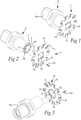
- Fig 1 shows the slot milling disc 1 mounted onto an end surface 3 of a rotatable shaft 2, whereas the slot milling disc 1 is in Fig 2 removed from the rotatable shaft such that the end surface 3 of the shaft is visible.
- the slot milling disc 1 comprises a thin and flat disc body 31 with a centre axis 4 and having a first side 5 with a bearing surface 6 adapted to bear against a mounting surface 7 on the end surface 3 of the shaft, and a second surface 8 adapted to be facing away from the shaft in the mounted state.
- the disc has an overall circular shape typically with a diameter of 80 - 320 mm and with an n-fold (in this case 10-fold) rotational symmetrical outer peripheral surface 9 having a number of parting and/or grooving blade projections 10, wherein each blade projection is in the vicinity of its tip provided with a recess in which a cutting insert 11 having a cutting edge 12 is mounted.
- the cutting inserts 11 are in the illustrated embodiments formed as parting and/or grooving inserts adapted to be used for cutting off or making slots/grooves in a work piece and are each provided with a comparatively long insert body having the cutting edge extending in the direction of the thickness of the disc body when mounted therein. Each cutting insert 11 is mounted in a seat with a clamping finger for securing it in the seat of the disc body.
- These cutting inserts are provided with a width of 1.5 - 8 mm, preferably 2 - 6 mm, and are designed for cutting action in the feed direction.
- the cutting edges 12 of the inserts 11 are somewhat wider than the thickness of the disc body in order to ensure clearance of the disc body from the work piece in the slot during cutting, such as for instance a 2 mm cutting insert width in case of a disc body thickness of 1.5 mm.
- the inserts may be manufactured from cemented carbide, or other hard/wear resistant material, such as high speed steel or ceramics. Such cutting inserts are also known for parting and/or grooving within the art of turning.
- the milling disc is also provided with a centre hole 14 in the disc body and attachment means in the form of four screw holes 15 distributed around the centre hole in the disc body.
- the rotatable shaft 2 is in the form of an adapter, which is intended for being mounted to an undisclosed machine for rotating the slot milling disc. More precisely, in the end to be attached to the machine, the adapter is provided with a quick coupling, Capto TM , disclosed in US 5 340 248 , comprising a conical and hollow shaft 16 having a somewhat "triangular", non-circular cross-section, which can be engaged by a pull rod not shown inside the shaft and drawn into a hole correspondingly shaped in the machine.
- Capto TM disclosed in US 5 340 248 , comprising a conical and hollow shaft 16 having a somewhat "triangular", non-circular cross-section, which can be engaged by a pull rod not shown inside the shaft and drawn into a hole correspondingly shaped in the machine.
- the shaft In the other end, to which the slot milling disc is to be mounted, the shaft is cylindrical and it is in the end surface 3 to be mounted towards the slot milling disc 1 provided with a projecting centre hub 17 and a surrounding mounting surface 7 adapted to abut the bearing surface 6 of the disc body.
- the shaft also comprises attachment means in the form of four screw holes 18 with internal threads for mounting screws 19.
- attachment means in the form of four screw holes 18 with internal threads for mounting screws 19.
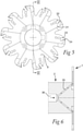
- Fig 4 illustrates how the slot milling disc according to this embodiment is designed in order to allow efficient flushing with fluid in the form of liquid and/or gas of the machined groove for washing away chips, cooling and/or lubrication during cutting operation.
- the disc is provided with as many flushing fluid channels 20 as blade projections 10 and cutting inserts 11.
- Each flushing fluid channel has a confined cross-section and extends within the disc body from an inlet opening 21 in a central part within said bearing surface 6 of the disc body to two outlet openings 22, 23 in the peripheral surface of the disc body.
- the inlet openings are formed as four elongated arch shaped or curved openings 21 which each correspond in shape and position to a curved opening 24 in the mounting surface 7 on the shaft.
- Each flushing fluid channel has an inner channel portion 25 extending from the inlet opening 21 into the blade projection 10 and to the outer tip 26 thereof, where it is plugged by a sealing member 27.
- the flushing fluid channel has also a first outer channel portion 28 branched from the inner channel portion at a location within the blade projection 10 while making an angle with the inner channel portion close to 90° and directed in a direction opposite to the intended rotation direction of the disc while pointing towards a rake surface of a cutting edge 12.
- Each flushing fluid channel has also a second outer channel portion 29 branched from the inner channel portion 25 in another direction than the first outer channel portion and directed towards the clearance side 30 of a cutting edge.
- the outlet opening 23 of the second outer channel portion is located in the tip of the blade projection 10 in the vicinity of and behind the cutting edge 12 of the blade projection as seen in the intended rotation direction of the disc.
- the different channel portions of the flushing fluid channel have typically a diameter of 0.5 mm - 1.1 mm with a diameter of the inner channel portion typically somewhat larger than the diameter of the first and second outer channel portion.
- the three channel portions of a flushing fluid channel all extending through a blade projection 10 may easily be produced, for instance through electrical discharge machining (EDM) or wire electrical discharge machining (WEDM).
- the jets of flushing fluid exiting the flushing fluid channel through the outlet openings 22, 23 of the first and second outer channel portions will efficiently remove cuttings and chips formed during a slot milling operation also when producing narrow slots.
- the first outer channel portion 28 directed towards a rake surface of a cutting edge will be particularly efficient in this respect.
- These narrow slots may for instance have a width of 2 - 6 mm and a depth of 20 - 120 mm.
- Fig 5 is a view of the disc body 31 of the slot milling disc of Fig. 4 being provided with a number of seats 32 for receiving cutting inserts at an outer peripheral surface thereof.
- this disc body is designed to form a slot milling disc according to Fig 4 by introducing, besides means for plugging 27, cutting inserts into the seats 32 while forcing opposite walls 33, 34 of the seat apart for holding a cutting insert with a cutting edge width slightly exceeding the thickness of the disc body 31 clamped under pretension therein.
- Fig 6 shows how branching channels 35 extend obliquely from a central fluid channel 36 of the mounting shaft 2 toward each feeding opening 24 adjacent to the outer periphery of the shaft end to be arranged flush with the inlet openings 21 in the disc body.
- Fig 7 illustrates schematically a slot milling disc according to a second embodiment of the invention, which differs from the slot milling disc according to the first embodiment by having a shaft 40 made in one piece with the disc body 41.
- the central fluid channel 42 extends in this embodiment through the entire shaft 40 and through the disc body 41 and has then been appropriately plugged through a screw 43 for diverting fluid coming from this central fluid channel 42 into the respective flushing fluid channels, which have the same appearance as the inner, first and second outer channel portions as in the first embodiment of the invention.
- this embodiment also differs in that the milling disc has a 4-fold rotational symmetrical design including four blade projections. This embodiment is suited for discs with smaller diameters.
- the plugging screw 43 is in Fig 7 shown in an extracted state and in Figs 8-10 engaging inner threads in the central fluid channel 42 for plugging this and only allowing flushing fluid to pass the screw by the two short bypass channel portions 44, 45 connecting the inner channel portions 25 of the four flushing fluid channels to the central fluid channel 42.
- the flushing fluid channels of the slot milling disc may beside the inner channel portion have only one of the first and second outer channel portions, and the first outer channel portion would then in most cases be preferred.
- the channel portions branched from the inner channel portion may make other angles than shown in the Figs for hitting the disc or slot machined at the desired cutting zone location of each cutting edge.
Landscapes
- Engineering & Computer Science (AREA)
- Mechanical Engineering (AREA)
- Milling Processes (AREA)
Claims (16)
- Nutenfrässcheibe zum Schneiden von Nuten oder Fugen mit einer gleichmäßigen Breite in ein Werkstück, wobei die Nutenfrässcheibe Folgendes aufweist- einen Scheibenkörper (31, 41), dessen äußere Umfangsfläche mit einer Anzahl von Schneidkanten (12) ausgestattet ist,- Befestigungsmittel (15), die so konfiguriert sind, dass eine die Rotation verhindernde Befestigung der Nutenfrässcheibe an einen rotierbaren Halteschaft (2) möglich ist, und- wenigstens einen Spülfluid-Kanal (20), der einen begrenzten Querschnitt aufweist und der sich in dem Scheibenkörper von einer Einlassöffnung (21), die in einem zentralen Bereich des Scheibenkörpers angeordnet ist und die so konfiguriert ist, dass sie mit einer Spülfluid-Quelle verbunden werden kann, bis zu wenigstens einer Auslassöffnung (22, 23) in der Umfangsfläche des Scheibenkörpers erstreckt,wobei der wenigstens eine Spülfluid-Kanal Folgendes aufweist- einen inneren Kanalabschnitt (25), der sich von der Einlassöffnung (21) in Richtung der Umfangsfläche erstreckt und endet, bevor er diese erreicht,- wenigstens einen äußeren Kanalabschnitt (28, 29), der sich von dem inneren Kanalabschnitt (25) erstreckt, während er die Richtung des Spülfluid-Kanals so ändert, dass sie in eine Richtung zu einer Schneidkante hin geneigt ist und sich zu der wenigstens einen Auslassöffnung (22, 23) erstreckt, wobei die Schneidkanten (12) durch separate Schneideinsätze (11) bereitgestellt werden, die in Einsatzsitzen (32) befestigt sind, die an der Umfangsfläche des Scheibenkörpers angeordnet sind, dadurch gekennzeichnet, dassder innere Kanalabschnitt (25) Teil eines Kanalabschnitts ist, der sich über den gesamten Weg zu der Umfangsfläche erstreckt und der dann mit Abdichtmitteln (27) abgedichtet wurde, und dadurch, dass die gesamte Nutenfrässcheibe aus einem Stück hergestellt ist mit Ausnahme der Abdichtmittel (27) und den Schneidkanten (12), wobei die Schneidkanten (12) breiter sind als eine Dicke des Scheibenkörpers, um während des Schneidens in einer Nut einen Freiraum des Scheibenkörpers von dem Werkstück zu sichern, und so gestaltet sind, dass sie in einem Werkstück eine Nut mit einer Breite von 1,5 bis 8 mm schneiden.
- Nutenfrässcheibe nach Anspruch 1, wobei die inneren (25) und äußeren (28, 29) Kanalabschnitte eine geradlinige Ausdehnung aufweisen.
- Nutenfrässcheibe nach Anspruch 1 oder 2, wobei der äußere Kanalabschnitt (28, 29) mit dem inneren Kanalabschnitt (25) einen Winkel von 60° bis 120° beschreibt.
- Nutenfrässcheibe nach einem der Ansprüche 1 bis 3, wobei der wenigstens eine äußere Kanalabschnitt (28) sich von dem inneren Kanalabschnitt (25) in Richtung einer Spanfläche der Schneidkante (12) in einer Richtung erstreckt, die zu der beabsichtigten Rotationsrichtung der Scheibe entgegengesetzt ist.
- Nutenfrässcheibe nach einem der Ansprüche 1 bis 3, wobei der wenigstens eine äußere Kanalabschnitt (29) sich von dem inneren Kanalabschnitt (25) in Richtung einer Freifläche (30) einer Schneidkante (12) in Richtung der beabsichtigten Rotationsrichtung erstreckt.
- Nutenfrässcheibe nach den Ansprüchen 4 und 5, wobei ein erster äußerer Kanalabschnitt (28) in Richtung der Spanfläche einer Schneidkante geneigt ist und ein zweiter äußerer Kanalabschnitt (29) in Richtung der Freifläche einer anderen Schneidkante geneigt ist.
- Nutenfrässcheibe nach einem der vorangehenden Ansprüche, wobei die äußere Umfangsfläche eine Anzahl von Schneidvorsprüngen (10) aufweist, jeweils mit einer Schneidkante (12) ausgestattet, wobei ein Spanraum (13) in Form einer Konkavität in der Umfangsfläche zwischen jedem Schneidvorsprung angeordnet ist, und wobei der innere Kanalabschnitt (25) sich von dem zentralen Bereich in jeden Schneidvorsprung (10) in Richtung einer äußeren Spitze (26) davon erstreckt.
- Nutenfrässcheibe nach Anspruch 7, wobei sich ein erster äußerer Kanalabschnitt (28) von dem inneren Kanalabschnitt (25) in einem Bereich innerhalb des Schneidvorsprungs (10) abzweigt und sich durch eine Auslassöffnung (22) in den Spanraum (13) öffnet, der hinter dem Schneidvorsprung angeordnet ist, gesehen in der beabsichtigten Rotationsrichtung der Scheibe und in Richtung zu einer Spanfläche der Schneidkante.
- Nutenfrässcheibe nach Anspruch 8, wobei sich ein zweiter äußerer Kanalabschnitt (29) von dem inneren Kanalabschnitt (25) in einer anderen Richtung als der erste äußere Kanalabschnitt (28) abzweigt und zu einer Freiseite (30) einer Schneidkante (12) gerichtet ist.
- Nutenfrässcheibe nach Anspruch 9, wobei sich der zweite äußere Kanalabschnitt (29) zu einer Auslassöffnung (23) in der Spitze (26) des Schneidvorsprungs erstreckt, in der Nähe von und hinter der Schneidkante (12) des Schneidvorsprungs (10), gesehen in der beabsichtigten Rotationsrichtung der Scheibe.
- Nutenfrässcheibe nach einem der vorangehenden Ansprüche, wobei die Einlassöffnung (21) wenigstens eine verlängerte Öffnung aufweist.
- Nutenfrässcheibe nach Anspruch 11, wobei die verlängerte Öffnung (21) bogenförmig ist.
- Nutenfrässcheibe nach Anspruch 12, wobei jede verlängerte bogenförmige (21) einen Krümmungsmittelpunkt aufweist, der mit einer zentralen Achse (4) der Scheibe konzentrisch ist.
- Nutenfrässcheibe nach einem der Ansprüche 11 bis 13, wobei zwei oder mehr Spülfluid-Kanäle (20) sich von einer gemeinsamen verlängerten Einlassöffnung (21) erstrecken.
- Nutenfrässcheibe nach einem der vorangehenden Ansprüche, wobei der Scheibenkörper eine erste Seitenfläche (5) aufweist, die eine Lagerfläche (6) um eine zentrale Achse (4) der Scheibe aufweist, und eine zweite Seitenfläche (8), die gegenüber der ersten Seitenfläche liegt, wobei die Befestigungsmittel (15) so konfiguriert sind, dass sie mit entsprechenden Befestigungsmitteln (18, 19) eines rotierbaren Halteschafts (12) interagieren, während sie die Lagerfläche (6) in Richtung einer Befestigungsfläche (7) an einer Endfläche des Schafts drücken, und wobei der Scheibenkörper eine Einlassöffnung (21) des wenigstens einen Spülfluid-Kanals (20) in seiner Lagerfläche (6) aufweist.
- Nutenfräswerkzeug mit einer Nutenfrässcheibe nach einem der vorangehenden Ansprüche und einem rotierbaren Halteschaft (2, 40), der rotationsverhindernd an der Nutenfrässcheibe zu befestigen ist, wobei der Schaft in Fluidkommunikation mit einem Fluidkanal (36, 42) innerhalb des Schaftes Einspeisöffnungen (24) in einer Endfläche davon aufweist, die so gestaltet und angeordnet sind, dass sie das Einspeisen von Spülfluid von dem Fluidkanal zu den Einlassöffnungen (21) der Nutenfrässcheibe ermöglichen.
Priority Applications (5)
| Application Number | Priority Date | Filing Date | Title |
|---|---|---|---|
| EP15189072.0A EP3153263B1 (de) | 2015-10-09 | 2015-10-09 | Nutenfrässcheibe und nutenfräser mit einer solchen nutenfrässcheibe |
| US15/766,127 US10710173B2 (en) | 2015-10-09 | 2016-10-07 | Slot milling disc, a slot milling tool comprising a slot milling disc and a disc for a milling disc |
| CN201680051520.2A CN108025378A (zh) | 2015-10-09 | 2016-10-07 | 狭槽铣削刀盘、包括狭槽铣削刀盘的狭槽铣削刀具和用于狭槽铣削刀盘的刀盘 |
| PCT/EP2016/073981 WO2017060415A1 (en) | 2015-10-09 | 2016-10-07 | A slot milling disc, a slot milling tool comprising a slot milling disc and a disc for a slot milling disc |
| JP2018517829A JP7058596B2 (ja) | 2015-10-09 | 2016-10-07 | 溝穴フライス加工ディスク、溝穴フライス加工ディスクを含む溝穴フライス工具、および溝穴フライス加工ディスク用のディスク |
Applications Claiming Priority (1)
| Application Number | Priority Date | Filing Date | Title |
|---|---|---|---|
| EP15189072.0A EP3153263B1 (de) | 2015-10-09 | 2015-10-09 | Nutenfrässcheibe und nutenfräser mit einer solchen nutenfrässcheibe |
Publications (2)
| Publication Number | Publication Date |
|---|---|
| EP3153263A1 EP3153263A1 (de) | 2017-04-12 |
| EP3153263B1 true EP3153263B1 (de) | 2022-02-23 |
Family
ID=54292670
Family Applications (1)
| Application Number | Title | Priority Date | Filing Date |
|---|---|---|---|
| EP15189072.0A Not-in-force EP3153263B1 (de) | 2015-10-09 | 2015-10-09 | Nutenfrässcheibe und nutenfräser mit einer solchen nutenfrässcheibe |
Country Status (5)
| Country | Link |
|---|---|
| US (1) | US10710173B2 (de) |
| EP (1) | EP3153263B1 (de) |
| JP (1) | JP7058596B2 (de) |
| CN (1) | CN108025378A (de) |
| WO (1) | WO2017060415A1 (de) |
Families Citing this family (25)
| Publication number | Priority date | Publication date | Assignee | Title |
|---|---|---|---|---|
| EP3321018B1 (de) * | 2016-11-09 | 2020-10-07 | Sandvik Intellectual Property AB | Scheibenfräser und kit mit solch einem scheibenfräser |
| DE102017112374A1 (de) * | 2017-06-06 | 2018-12-06 | Komet Group Gmbh | Fräswerkzeug mit wechselbarem Schneidring |
| TWI768142B (zh) * | 2017-11-29 | 2022-06-21 | 以色列商艾斯卡公司 | 具有向內偏置嵌件接納槽的開槽刀具本體、及具有該本體的旋轉槽切削刀具 |
| US10710174B2 (en) * | 2017-11-30 | 2020-07-14 | Iscar, Ltd. | Slitting cutter and tool key in combination therewith |
| US11420272B2 (en) * | 2019-01-08 | 2022-08-23 | Iscar, Ltd. | Milling head having integrally formed cutting edges and rotary milling tool |
| EP3736072A1 (de) * | 2019-05-07 | 2020-11-11 | AB Sandvik Coromant | Fräswerkzeug mit kühlmittelverteilenden löchern |
| JP6769530B1 (ja) * | 2019-06-28 | 2020-10-14 | 株式会社タンガロイ | 切削工具 |
| US11420273B2 (en) * | 2019-10-17 | 2022-08-23 | Kennametal Inc. | Rotary cutting tools and applications thereof |
| JP7494466B2 (ja) * | 2019-12-19 | 2024-06-04 | 三菱マテリアル株式会社 | クーラント孔付きスロッティングカッターの取付部材 |
| JP7419792B2 (ja) * | 2019-12-19 | 2024-01-23 | 三菱マテリアル株式会社 | クーラント孔付きスロッティングカッターおよび該クーラント孔付きスロッティングカッターの取付部材 |
| JP2021160043A (ja) * | 2020-03-31 | 2021-10-11 | 三菱マテリアル株式会社 | 刃先交換式切削工具および工具本体 |
| US11938551B2 (en) * | 2020-06-18 | 2024-03-26 | Ford Global Technologies, Llc | 3D printed gear cutting tools with capillaries for minimum quantity lubrication, gas or liquid |
| EP4171854B1 (de) * | 2020-06-30 | 2024-08-21 | Iscar Ltd. | Indexierbare trennklinge mit kreisenden kühlkanälen |
| CN112139576A (zh) * | 2020-10-20 | 2020-12-29 | 常熟万克精密工具有限公司 | 一种t型铣槽刀 |
| EP4043130A1 (de) * | 2021-02-10 | 2022-08-17 | CERATIZIT Austria Gesellschaft m.b.H. | Scheibenfräser |
| CN112792391B (zh) * | 2021-04-12 | 2021-08-03 | 成都飞机工业(集团)有限责任公司 | 一种基于内冷槽铣刀的蜂窝材料加工方法 |
| US11597019B2 (en) * | 2021-05-03 | 2023-03-07 | Iscar, Ltd. | Slotting tool body having insert receiving slots connected by flexibility recess and rotary slot cutting tool having same |
| KR102611096B1 (ko) * | 2021-10-25 | 2023-12-11 | 한국생산기술연구원 | 다공성 구조의 내부 냉각 유로 가지는 절삭공구 |
| US12275069B2 (en) * | 2022-07-01 | 2025-04-15 | Iscar, Ltd. | Cutting blade having a clamping bore with a coolant inlet, blade holder and cutting tool |
| JP7340168B1 (ja) | 2022-12-21 | 2023-09-07 | 株式会社タンガロイ | 切削工具とそのボディ |
| CN116100085B (zh) * | 2022-12-29 | 2024-02-09 | 江苏速利达齿轮有限公司 | 一种齿轮轴加工装置 |
| WO2024195284A1 (ja) * | 2023-03-20 | 2024-09-26 | 京セラ株式会社 | 切削工具及び切削加工物の製造方法 |
| WO2024195286A1 (ja) * | 2023-03-20 | 2024-09-26 | 京セラ株式会社 | ホルダ、切削工具及び切削加工物の製造方法 |
| US20250010382A1 (en) | 2023-07-06 | 2025-01-09 | Iscar, Ltd. | Milling head with through hole having centering and drive surfaces at tooth-receiving lobes, tool holder and rotary milling tool |
| CN120347270A (zh) * | 2025-06-19 | 2025-07-22 | 江苏双星特钢有限公司 | 一种用于加工铸钢件的高速切削设备 |
Family Cites Families (24)
| Publication number | Priority date | Publication date | Assignee | Title |
|---|---|---|---|---|
| FR1115922A (fr) * | 1954-06-29 | 1956-05-02 | Outils de coupe | |
| US3597817A (en) * | 1969-03-20 | 1971-08-10 | Howard M Whalley | Tee-slot cutter and method for using it |
| JPS55120927A (en) * | 1979-03-07 | 1980-09-17 | Tani Seikiyo Kk | Circular saw with guide groove cut in inside surface, and device using the same |
| JPS6021135Y2 (ja) * | 1980-06-26 | 1985-06-24 | 株式会社神戸製鋼所 | 油孔付丸鋸 |
| DE3105933A1 (de) * | 1981-02-11 | 1982-08-19 | Carl Hurth Maschinen- und Zahnradfabrik GmbH & Co, 8000 München | Verfahren zum kuehlen eines fraeswerkzeugs, insbesondere an seinen schneidkanten und dafuer geeignetes fraeswerkzeug |
| DE3104752A1 (de) * | 1981-02-11 | 1982-08-19 | Carl Hurth Maschinen- und Zahnradfabrik GmbH & Co, 8000 München | Verfahren zum kuehlen eines fraeswerkzeugs, insbesondere an seinen schneidkanten, und dafuer geeignetes fraeswerkzeug |
| US4516560A (en) * | 1982-07-29 | 1985-05-14 | Federal-Mogul Corporation | Abrasive cutting wheel and method of cutting abradable material |
| JPH0167006U (de) * | 1987-10-22 | 1989-04-28 | ||
| DE4224296A1 (de) | 1991-08-21 | 1994-01-27 | Sandvik Gmbh | Mechanische Spannvorrichtung mit Adapterteil |
| JPH0631579A (ja) * | 1992-07-20 | 1994-02-08 | Genichi Sato | 切削工具 |
| US5290135A (en) * | 1992-10-28 | 1994-03-01 | The Gleason Works | Rotary ring cutter having coolant distribution and discharge means |
| JPH10263911A (ja) * | 1997-03-25 | 1998-10-06 | Hitachi Ltd | 深溝加工用カッター |
| SE517817C2 (sv) * | 2000-02-11 | 2002-07-16 | Sandvik Ab | Verktyg för spånavskiljande bearbetning med spårformade kylmedelskanaler i ändytan |
| DE10145006A1 (de) | 2001-09-12 | 2003-04-03 | Maier Gmbh | Scheibenfräserkühlung |
| EP1682300A1 (de) * | 2003-11-07 | 2006-07-26 | James Hardie International Finance B.V. | Schneidwerkzeug |
| US20060288993A1 (en) * | 2005-06-27 | 2006-12-28 | Anthony Baratta | Tools and methods for making and using tools, blades and methods of making and using blades |
| US20080131216A1 (en) * | 2006-12-05 | 2008-06-05 | Pratt & Whitney Canada Corp. | Cup mill for airfoils |
| DE102007022310A1 (de) * | 2007-05-12 | 2008-11-13 | Arno Friedrichs | Verfahren zur Herstellung eines Kühlkanäle aufweisenden Kreissägeblattes |
| DE102011003714B8 (de) * | 2011-02-07 | 2012-08-30 | Mag Ias Gmbh | Bearbeitungseinrichtung zum Bearbeiten von Kurbelwellen sowie Bearbeitungssystem mit einer derartigen Bearbeitungseinrichtung |
| CN201960145U (zh) * | 2011-04-02 | 2011-09-07 | 四川天虎工具有限责任公司 | 模块式多工位曲轴车刀盘 |
| US9259788B2 (en) * | 2012-03-06 | 2016-02-16 | Iscar, Ltd. | Parting blade and blade holder configured for conveyance of pressurized coolant |
| EP2929967B1 (de) * | 2014-04-11 | 2017-02-01 | Sandvik Intellectual Property AB | Langlochfrässcheibe und drehbarer Aufnahmeschaft für eine solche Frässcheibe |
| DE102014012481A1 (de) * | 2014-08-27 | 2016-03-03 | Rosswag Gmbh | Scheibenfräser und Herstellverfahren |
| US10137549B2 (en) * | 2015-04-08 | 2018-11-27 | Decatur Diamond, Llc | Milling cutter with lubrication conduits |
-
2015
- 2015-10-09 EP EP15189072.0A patent/EP3153263B1/de not_active Not-in-force
-
2016
- 2016-10-07 CN CN201680051520.2A patent/CN108025378A/zh active Pending
- 2016-10-07 JP JP2018517829A patent/JP7058596B2/ja not_active Expired - Fee Related
- 2016-10-07 WO PCT/EP2016/073981 patent/WO2017060415A1/en not_active Ceased
- 2016-10-07 US US15/766,127 patent/US10710173B2/en not_active Expired - Fee Related
Also Published As
| Publication number | Publication date |
|---|---|
| JP7058596B2 (ja) | 2022-04-22 |
| US10710173B2 (en) | 2020-07-14 |
| WO2017060415A1 (en) | 2017-04-13 |
| US20180290218A1 (en) | 2018-10-11 |
| CN108025378A (zh) | 2018-05-11 |
| JP2018534158A (ja) | 2018-11-22 |
| EP3153263A1 (de) | 2017-04-12 |
Similar Documents
| Publication | Publication Date | Title |
|---|---|---|
| US10710173B2 (en) | Slot milling disc, a slot milling tool comprising a slot milling disc and a disc for a milling disc | |
| US9676043B2 (en) | Slot milling disc and a rotatable mounting shaft for such a milling disc | |
| CN109789498B (zh) | 盘形铣刀和包括该盘形铣刀的套件 | |
| US9579727B2 (en) | Cutting assembly with cutting insert having enhanced coolant delivery | |
| KR102291712B1 (ko) | 냉각제 편향을 갖는 절삭 공구 | |
| CN110709200B (zh) | 切削工具 | |
| CN102196872A (zh) | 孔内表面的切削工具以及孔内表面的切削方法 | |
| CA3079630C (en) | Whirling tool | |
| CN118162642A (zh) | 刀刃可更换式切削工具及切削刀片 | |
| JP2024087522A (ja) | ドリルヘッド及び刃先交換式ドリル | |
| JP7494466B2 (ja) | クーラント孔付きスロッティングカッターの取付部材 | |
| CN116900369A (zh) | 非标机夹式bta深孔钻削刀片及刀具 | |
| EP4616983A1 (de) | Schneidwerkzeug mit düse | |
| JP2018130774A (ja) | 刃先交換式エンドミルのエンドミル本体および刃先交換式エンドミル | |
| JP2018001297A (ja) | 穴加工工具 | |
| WO2023090153A1 (ja) | ホルダ、切削工具及び切削加工物の製造方法 | |
| CN120055346A (zh) | 工具、用于工具的切割装置以及用于制造工具的方法 |
Legal Events
| Date | Code | Title | Description |
|---|---|---|---|
| PUAI | Public reference made under article 153(3) epc to a published international application that has entered the european phase |
Free format text: ORIGINAL CODE: 0009012 |
|
| STAA | Information on the status of an ep patent application or granted ep patent |
Free format text: STATUS: THE APPLICATION HAS BEEN PUBLISHED |
|
| AK | Designated contracting states |
Kind code of ref document: A1 Designated state(s): AL AT BE BG CH CY CZ DE DK EE ES FI FR GB GR HR HU IE IS IT LI LT LU LV MC MK MT NL NO PL PT RO RS SE SI SK SM TR |
|
| AX | Request for extension of the european patent |
Extension state: BA ME |
|
| STAA | Information on the status of an ep patent application or granted ep patent |
Free format text: STATUS: REQUEST FOR EXAMINATION WAS MADE |
|
| 17P | Request for examination filed |
Effective date: 20171012 |
|
| RBV | Designated contracting states (corrected) |
Designated state(s): AL AT BE BG CH CY CZ DE DK EE ES FI FR GB GR HR HU IE IS IT LI LT LU LV MC MK MT NL NO PL PT RO RS SE SI SK SM TR |
|
| STAA | Information on the status of an ep patent application or granted ep patent |
Free format text: STATUS: EXAMINATION IS IN PROGRESS |
|
| 17Q | First examination report despatched |
Effective date: 20191015 |
|
| GRAP | Despatch of communication of intention to grant a patent |
Free format text: ORIGINAL CODE: EPIDOSNIGR1 |
|
| STAA | Information on the status of an ep patent application or granted ep patent |
Free format text: STATUS: GRANT OF PATENT IS INTENDED |
|
| INTG | Intention to grant announced |
Effective date: 20211019 |
|
| GRAS | Grant fee paid |
Free format text: ORIGINAL CODE: EPIDOSNIGR3 |
|
| GRAA | (expected) grant |
Free format text: ORIGINAL CODE: 0009210 |
|
| STAA | Information on the status of an ep patent application or granted ep patent |
Free format text: STATUS: THE PATENT HAS BEEN GRANTED |
|
| AK | Designated contracting states |
Kind code of ref document: B1 Designated state(s): AL AT BE BG CH CY CZ DE DK EE ES FI FR GB GR HR HU IE IS IT LI LT LU LV MC MK MT NL NO PL PT RO RS SE SI SK SM TR |
|
| REG | Reference to a national code |
Ref country code: GB Ref legal event code: FG4D |
|
| REG | Reference to a national code |
Ref country code: CH Ref legal event code: EP |
|
| REG | Reference to a national code |
Ref country code: DE Ref legal event code: R096 Ref document number: 602015077047 Country of ref document: DE |
|
| REG | Reference to a national code |
Ref country code: AT Ref legal event code: REF Ref document number: 1470050 Country of ref document: AT Kind code of ref document: T Effective date: 20220315 |
|
| REG | Reference to a national code |
Ref country code: IE Ref legal event code: FG4D |
|
| REG | Reference to a national code |
Ref country code: LT Ref legal event code: MG9D |
|
| REG | Reference to a national code |
Ref country code: NL Ref legal event code: MP Effective date: 20220223 |
|
| REG | Reference to a national code |
Ref country code: AT Ref legal event code: MK05 Ref document number: 1470050 Country of ref document: AT Kind code of ref document: T Effective date: 20220223 |
|
| PG25 | Lapsed in a contracting state [announced via postgrant information from national office to epo] |
Ref country code: SE Free format text: LAPSE BECAUSE OF FAILURE TO SUBMIT A TRANSLATION OF THE DESCRIPTION OR TO PAY THE FEE WITHIN THE PRESCRIBED TIME-LIMIT Effective date: 20220223 Ref country code: RS Free format text: LAPSE BECAUSE OF FAILURE TO SUBMIT A TRANSLATION OF THE DESCRIPTION OR TO PAY THE FEE WITHIN THE PRESCRIBED TIME-LIMIT Effective date: 20220223 Ref country code: PT Free format text: LAPSE BECAUSE OF FAILURE TO SUBMIT A TRANSLATION OF THE DESCRIPTION OR TO PAY THE FEE WITHIN THE PRESCRIBED TIME-LIMIT Effective date: 20220623 Ref country code: NO Free format text: LAPSE BECAUSE OF FAILURE TO SUBMIT A TRANSLATION OF THE DESCRIPTION OR TO PAY THE FEE WITHIN THE PRESCRIBED TIME-LIMIT Effective date: 20220523 Ref country code: NL Free format text: LAPSE BECAUSE OF FAILURE TO SUBMIT A TRANSLATION OF THE DESCRIPTION OR TO PAY THE FEE WITHIN THE PRESCRIBED TIME-LIMIT Effective date: 20220223 Ref country code: LT Free format text: LAPSE BECAUSE OF FAILURE TO SUBMIT A TRANSLATION OF THE DESCRIPTION OR TO PAY THE FEE WITHIN THE PRESCRIBED TIME-LIMIT Effective date: 20220223 Ref country code: HR Free format text: LAPSE BECAUSE OF FAILURE TO SUBMIT A TRANSLATION OF THE DESCRIPTION OR TO PAY THE FEE WITHIN THE PRESCRIBED TIME-LIMIT Effective date: 20220223 Ref country code: ES Free format text: LAPSE BECAUSE OF FAILURE TO SUBMIT A TRANSLATION OF THE DESCRIPTION OR TO PAY THE FEE WITHIN THE PRESCRIBED TIME-LIMIT Effective date: 20220223 Ref country code: BG Free format text: LAPSE BECAUSE OF FAILURE TO SUBMIT A TRANSLATION OF THE DESCRIPTION OR TO PAY THE FEE WITHIN THE PRESCRIBED TIME-LIMIT Effective date: 20220523 |
|
| PG25 | Lapsed in a contracting state [announced via postgrant information from national office to epo] |
Ref country code: PL Free format text: LAPSE BECAUSE OF FAILURE TO SUBMIT A TRANSLATION OF THE DESCRIPTION OR TO PAY THE FEE WITHIN THE PRESCRIBED TIME-LIMIT Effective date: 20220223 Ref country code: LV Free format text: LAPSE BECAUSE OF FAILURE TO SUBMIT A TRANSLATION OF THE DESCRIPTION OR TO PAY THE FEE WITHIN THE PRESCRIBED TIME-LIMIT Effective date: 20220223 Ref country code: GR Free format text: LAPSE BECAUSE OF FAILURE TO SUBMIT A TRANSLATION OF THE DESCRIPTION OR TO PAY THE FEE WITHIN THE PRESCRIBED TIME-LIMIT Effective date: 20220524 Ref country code: FI Free format text: LAPSE BECAUSE OF FAILURE TO SUBMIT A TRANSLATION OF THE DESCRIPTION OR TO PAY THE FEE WITHIN THE PRESCRIBED TIME-LIMIT Effective date: 20220223 Ref country code: AT Free format text: LAPSE BECAUSE OF FAILURE TO SUBMIT A TRANSLATION OF THE DESCRIPTION OR TO PAY THE FEE WITHIN THE PRESCRIBED TIME-LIMIT Effective date: 20220223 |
|
| PG25 | Lapsed in a contracting state [announced via postgrant information from national office to epo] |
Ref country code: IS Free format text: LAPSE BECAUSE OF FAILURE TO SUBMIT A TRANSLATION OF THE DESCRIPTION OR TO PAY THE FEE WITHIN THE PRESCRIBED TIME-LIMIT Effective date: 20220623 |
|
| PG25 | Lapsed in a contracting state [announced via postgrant information from national office to epo] |
Ref country code: SM Free format text: LAPSE BECAUSE OF FAILURE TO SUBMIT A TRANSLATION OF THE DESCRIPTION OR TO PAY THE FEE WITHIN THE PRESCRIBED TIME-LIMIT Effective date: 20220223 Ref country code: SK Free format text: LAPSE BECAUSE OF FAILURE TO SUBMIT A TRANSLATION OF THE DESCRIPTION OR TO PAY THE FEE WITHIN THE PRESCRIBED TIME-LIMIT Effective date: 20220223 Ref country code: RO Free format text: LAPSE BECAUSE OF FAILURE TO SUBMIT A TRANSLATION OF THE DESCRIPTION OR TO PAY THE FEE WITHIN THE PRESCRIBED TIME-LIMIT Effective date: 20220223 Ref country code: EE Free format text: LAPSE BECAUSE OF FAILURE TO SUBMIT A TRANSLATION OF THE DESCRIPTION OR TO PAY THE FEE WITHIN THE PRESCRIBED TIME-LIMIT Effective date: 20220223 Ref country code: DK Free format text: LAPSE BECAUSE OF FAILURE TO SUBMIT A TRANSLATION OF THE DESCRIPTION OR TO PAY THE FEE WITHIN THE PRESCRIBED TIME-LIMIT Effective date: 20220223 Ref country code: CZ Free format text: LAPSE BECAUSE OF FAILURE TO SUBMIT A TRANSLATION OF THE DESCRIPTION OR TO PAY THE FEE WITHIN THE PRESCRIBED TIME-LIMIT Effective date: 20220223 |
|
| PGFP | Annual fee paid to national office [announced via postgrant information from national office to epo] |
Ref country code: GB Payment date: 20220901 Year of fee payment: 8 |
|
| REG | Reference to a national code |
Ref country code: DE Ref legal event code: R097 Ref document number: 602015077047 Country of ref document: DE |
|
| PG25 | Lapsed in a contracting state [announced via postgrant information from national office to epo] |
Ref country code: AL Free format text: LAPSE BECAUSE OF FAILURE TO SUBMIT A TRANSLATION OF THE DESCRIPTION OR TO PAY THE FEE WITHIN THE PRESCRIBED TIME-LIMIT Effective date: 20220223 |
|
| PGFP | Annual fee paid to national office [announced via postgrant information from national office to epo] |
Ref country code: FR Payment date: 20220921 Year of fee payment: 8 |
|
| PLBE | No opposition filed within time limit |
Free format text: ORIGINAL CODE: 0009261 |
|
| STAA | Information on the status of an ep patent application or granted ep patent |
Free format text: STATUS: NO OPPOSITION FILED WITHIN TIME LIMIT |
|
| PGFP | Annual fee paid to national office [announced via postgrant information from national office to epo] |
Ref country code: IT Payment date: 20220913 Year of fee payment: 8 |
|
| 26N | No opposition filed |
Effective date: 20221124 |
|
| PG25 | Lapsed in a contracting state [announced via postgrant information from national office to epo] |
Ref country code: SI Free format text: LAPSE BECAUSE OF FAILURE TO SUBMIT A TRANSLATION OF THE DESCRIPTION OR TO PAY THE FEE WITHIN THE PRESCRIBED TIME-LIMIT Effective date: 20220223 |
|
| PG25 | Lapsed in a contracting state [announced via postgrant information from national office to epo] |
Ref country code: MC Free format text: LAPSE BECAUSE OF FAILURE TO SUBMIT A TRANSLATION OF THE DESCRIPTION OR TO PAY THE FEE WITHIN THE PRESCRIBED TIME-LIMIT Effective date: 20220223 |
|
| REG | Reference to a national code |
Ref country code: CH Ref legal event code: PL |
|
| REG | Reference to a national code |
Ref country code: BE Ref legal event code: MM Effective date: 20221031 |
|
| PG25 | Lapsed in a contracting state [announced via postgrant information from national office to epo] |
Ref country code: LU Free format text: LAPSE BECAUSE OF NON-PAYMENT OF DUE FEES Effective date: 20221009 |
|
| P01 | Opt-out of the competence of the unified patent court (upc) registered |
Effective date: 20230603 |
|
| PG25 | Lapsed in a contracting state [announced via postgrant information from national office to epo] |
Ref country code: LI Free format text: LAPSE BECAUSE OF NON-PAYMENT OF DUE FEES Effective date: 20221031 Ref country code: CH Free format text: LAPSE BECAUSE OF NON-PAYMENT OF DUE FEES Effective date: 20221031 |
|
| PG25 | Lapsed in a contracting state [announced via postgrant information from national office to epo] |
Ref country code: BE Free format text: LAPSE BECAUSE OF NON-PAYMENT OF DUE FEES Effective date: 20221031 |
|
| PG25 | Lapsed in a contracting state [announced via postgrant information from national office to epo] |
Ref country code: IE Free format text: LAPSE BECAUSE OF NON-PAYMENT OF DUE FEES Effective date: 20221009 |
|
| PGFP | Annual fee paid to national office [announced via postgrant information from national office to epo] |
Ref country code: DE Payment date: 20230906 Year of fee payment: 9 |
|
| PG25 | Lapsed in a contracting state [announced via postgrant information from national office to epo] |
Ref country code: HU Free format text: LAPSE BECAUSE OF FAILURE TO SUBMIT A TRANSLATION OF THE DESCRIPTION OR TO PAY THE FEE WITHIN THE PRESCRIBED TIME-LIMIT; INVALID AB INITIO Effective date: 20151009 |
|
| PG25 | Lapsed in a contracting state [announced via postgrant information from national office to epo] |
Ref country code: CY Free format text: LAPSE BECAUSE OF FAILURE TO SUBMIT A TRANSLATION OF THE DESCRIPTION OR TO PAY THE FEE WITHIN THE PRESCRIBED TIME-LIMIT Effective date: 20220223 |
|
| PG25 | Lapsed in a contracting state [announced via postgrant information from national office to epo] |
Ref country code: MK Free format text: LAPSE BECAUSE OF FAILURE TO SUBMIT A TRANSLATION OF THE DESCRIPTION OR TO PAY THE FEE WITHIN THE PRESCRIBED TIME-LIMIT Effective date: 20220223 |
|
| GBPC | Gb: european patent ceased through non-payment of renewal fee |
Effective date: 20231009 |
|
| PG25 | Lapsed in a contracting state [announced via postgrant information from national office to epo] |
Ref country code: TR Free format text: LAPSE BECAUSE OF FAILURE TO SUBMIT A TRANSLATION OF THE DESCRIPTION OR TO PAY THE FEE WITHIN THE PRESCRIBED TIME-LIMIT Effective date: 20220223 |
|
| PG25 | Lapsed in a contracting state [announced via postgrant information from national office to epo] |
Ref country code: GB Free format text: LAPSE BECAUSE OF NON-PAYMENT OF DUE FEES Effective date: 20231009 |
|
| PG25 | Lapsed in a contracting state [announced via postgrant information from national office to epo] |
Ref country code: GB Free format text: LAPSE BECAUSE OF NON-PAYMENT OF DUE FEES Effective date: 20231009 Ref country code: FR Free format text: LAPSE BECAUSE OF NON-PAYMENT OF DUE FEES Effective date: 20231031 |
|
| PG25 | Lapsed in a contracting state [announced via postgrant information from national office to epo] |
Ref country code: MT Free format text: LAPSE BECAUSE OF FAILURE TO SUBMIT A TRANSLATION OF THE DESCRIPTION OR TO PAY THE FEE WITHIN THE PRESCRIBED TIME-LIMIT Effective date: 20220223 |
|
| PG25 | Lapsed in a contracting state [announced via postgrant information from national office to epo] |
Ref country code: IT Free format text: LAPSE BECAUSE OF NON-PAYMENT OF DUE FEES Effective date: 20231009 |
|
| PG25 | Lapsed in a contracting state [announced via postgrant information from national office to epo] |
Ref country code: IT Free format text: LAPSE BECAUSE OF NON-PAYMENT OF DUE FEES Effective date: 20231009 |
|
| REG | Reference to a national code |
Ref country code: DE Ref legal event code: R119 Ref document number: 602015077047 Country of ref document: DE |
|
| PG25 | Lapsed in a contracting state [announced via postgrant information from national office to epo] |
Ref country code: DE Free format text: LAPSE BECAUSE OF NON-PAYMENT OF DUE FEES Effective date: 20250501 |