EP3154604B1 - Umpe zur implantierung in ein gefäss - Google Patents
Umpe zur implantierung in ein gefäss Download PDFInfo
- Publication number
- EP3154604B1 EP3154604B1 EP15730096.3A EP15730096A EP3154604B1 EP 3154604 B1 EP3154604 B1 EP 3154604B1 EP 15730096 A EP15730096 A EP 15730096A EP 3154604 B1 EP3154604 B1 EP 3154604B1
- Authority
- EP
- European Patent Office
- Prior art keywords
- pump
- state
- set forth
- rotor
- stator
- Prior art date
- Legal status (The legal status is an assumption and is not a legal conclusion. Google has not performed a legal analysis and makes no representation as to the accuracy of the status listed.)
- Active
Links
Images




Classifications
-
- A—HUMAN NECESSITIES
- A61—MEDICAL OR VETERINARY SCIENCE; HYGIENE
- A61M—DEVICES FOR INTRODUCING MEDIA INTO, OR ONTO, THE BODY; DEVICES FOR TRANSDUCING BODY MEDIA OR FOR TAKING MEDIA FROM THE BODY; DEVICES FOR PRODUCING OR ENDING SLEEP OR STUPOR
- A61M60/00—Blood pumps; Devices for mechanical circulatory actuation; Balloon pumps for circulatory assistance
- A61M60/40—Details relating to driving
- A61M60/403—Details relating to driving for non-positive displacement blood pumps
- A61M60/419—Details relating to driving for non-positive displacement blood pumps the force acting on the blood contacting member being permanent magnetic, e.g. from a rotating magnetic coupling between driving and driven magnets
-
- A—HUMAN NECESSITIES
- A61—MEDICAL OR VETERINARY SCIENCE; HYGIENE
- A61M—DEVICES FOR INTRODUCING MEDIA INTO, OR ONTO, THE BODY; DEVICES FOR TRANSDUCING BODY MEDIA OR FOR TAKING MEDIA FROM THE BODY; DEVICES FOR PRODUCING OR ENDING SLEEP OR STUPOR
- A61M60/00—Blood pumps; Devices for mechanical circulatory actuation; Balloon pumps for circulatory assistance
- A61M60/40—Details relating to driving
- A61M60/403—Details relating to driving for non-positive displacement blood pumps
- A61M60/422—Details relating to driving for non-positive displacement blood pumps the force acting on the blood contacting member being electromagnetic, e.g. using canned motor pumps
-
- A—HUMAN NECESSITIES
- A61—MEDICAL OR VETERINARY SCIENCE; HYGIENE
- A61M—DEVICES FOR INTRODUCING MEDIA INTO, OR ONTO, THE BODY; DEVICES FOR TRANSDUCING BODY MEDIA OR FOR TAKING MEDIA FROM THE BODY; DEVICES FOR PRODUCING OR ENDING SLEEP OR STUPOR
- A61M60/00—Blood pumps; Devices for mechanical circulatory actuation; Balloon pumps for circulatory assistance
- A61M60/10—Location thereof with respect to the patient's body
- A61M60/122—Implantable pumps or pumping devices, i.e. the blood being pumped inside the patient's body
- A61M60/126—Implantable pumps or pumping devices, i.e. the blood being pumped inside the patient's body implantable via, into, inside, in line, branching on, or around a blood vessel
- A61M60/13—Implantable pumps or pumping devices, i.e. the blood being pumped inside the patient's body implantable via, into, inside, in line, branching on, or around a blood vessel by means of a catheter allowing explantation, e.g. catheter pumps temporarily introduced via the vascular system
-
- A—HUMAN NECESSITIES
- A61—MEDICAL OR VETERINARY SCIENCE; HYGIENE
- A61M—DEVICES FOR INTRODUCING MEDIA INTO, OR ONTO, THE BODY; DEVICES FOR TRANSDUCING BODY MEDIA OR FOR TAKING MEDIA FROM THE BODY; DEVICES FOR PRODUCING OR ENDING SLEEP OR STUPOR
- A61M60/00—Blood pumps; Devices for mechanical circulatory actuation; Balloon pumps for circulatory assistance
- A61M60/20—Type thereof
- A61M60/205—Non-positive displacement blood pumps
- A61M60/216—Non-positive displacement blood pumps including a rotating member acting on the blood, e.g. impeller
- A61M60/221—Non-positive displacement blood pumps including a rotating member acting on the blood, e.g. impeller the blood flow through the rotating member having both radial and axial components, e.g. mixed flow pumps
-
- A—HUMAN NECESSITIES
- A61—MEDICAL OR VETERINARY SCIENCE; HYGIENE
- A61M—DEVICES FOR INTRODUCING MEDIA INTO, OR ONTO, THE BODY; DEVICES FOR TRANSDUCING BODY MEDIA OR FOR TAKING MEDIA FROM THE BODY; DEVICES FOR PRODUCING OR ENDING SLEEP OR STUPOR
- A61M60/00—Blood pumps; Devices for mechanical circulatory actuation; Balloon pumps for circulatory assistance
- A61M60/20—Type thereof
- A61M60/205—Non-positive displacement blood pumps
- A61M60/216—Non-positive displacement blood pumps including a rotating member acting on the blood, e.g. impeller
- A61M60/237—Non-positive displacement blood pumps including a rotating member acting on the blood, e.g. impeller the blood flow through the rotating member having mainly axial components, e.g. axial flow pumps
-
- A—HUMAN NECESSITIES
- A61—MEDICAL OR VETERINARY SCIENCE; HYGIENE
- A61M—DEVICES FOR INTRODUCING MEDIA INTO, OR ONTO, THE BODY; DEVICES FOR TRANSDUCING BODY MEDIA OR FOR TAKING MEDIA FROM THE BODY; DEVICES FOR PRODUCING OR ENDING SLEEP OR STUPOR
- A61M60/00—Blood pumps; Devices for mechanical circulatory actuation; Balloon pumps for circulatory assistance
- A61M60/40—Details relating to driving
- A61M60/403—Details relating to driving for non-positive displacement blood pumps
- A61M60/405—Details relating to driving for non-positive displacement blood pumps the force acting on the blood contacting member being hydraulic or pneumatic
-
- A—HUMAN NECESSITIES
- A61—MEDICAL OR VETERINARY SCIENCE; HYGIENE
- A61M—DEVICES FOR INTRODUCING MEDIA INTO, OR ONTO, THE BODY; DEVICES FOR TRANSDUCING BODY MEDIA OR FOR TAKING MEDIA FROM THE BODY; DEVICES FOR PRODUCING OR ENDING SLEEP OR STUPOR
- A61M60/00—Blood pumps; Devices for mechanical circulatory actuation; Balloon pumps for circulatory assistance
- A61M60/40—Details relating to driving
- A61M60/403—Details relating to driving for non-positive displacement blood pumps
- A61M60/408—Details relating to driving for non-positive displacement blood pumps the force acting on the blood contacting member being mechanical, e.g. transmitted by a shaft or cable
- A61M60/411—Details relating to driving for non-positive displacement blood pumps the force acting on the blood contacting member being mechanical, e.g. transmitted by a shaft or cable generated by an electromotor
- A61M60/416—Details relating to driving for non-positive displacement blood pumps the force acting on the blood contacting member being mechanical, e.g. transmitted by a shaft or cable generated by an electromotor transmitted directly by the motor rotor drive shaft
-
- A—HUMAN NECESSITIES
- A61—MEDICAL OR VETERINARY SCIENCE; HYGIENE
- A61M—DEVICES FOR INTRODUCING MEDIA INTO, OR ONTO, THE BODY; DEVICES FOR TRANSDUCING BODY MEDIA OR FOR TAKING MEDIA FROM THE BODY; DEVICES FOR PRODUCING OR ENDING SLEEP OR STUPOR
- A61M60/00—Blood pumps; Devices for mechanical circulatory actuation; Balloon pumps for circulatory assistance
- A61M60/50—Details relating to control
- A61M60/508—Electronic control means, e.g. for feedback regulation
- A61M60/515—Regulation using real-time patient data
-
- A—HUMAN NECESSITIES
- A61—MEDICAL OR VETERINARY SCIENCE; HYGIENE
- A61M—DEVICES FOR INTRODUCING MEDIA INTO, OR ONTO, THE BODY; DEVICES FOR TRANSDUCING BODY MEDIA OR FOR TAKING MEDIA FROM THE BODY; DEVICES FOR PRODUCING OR ENDING SLEEP OR STUPOR
- A61M60/00—Blood pumps; Devices for mechanical circulatory actuation; Balloon pumps for circulatory assistance
- A61M60/50—Details relating to control
- A61M60/508—Electronic control means, e.g. for feedback regulation
- A61M60/515—Regulation using real-time patient data
- A61M60/531—Regulation using real-time patient data using blood pressure data, e.g. from blood pressure sensors
-
- A—HUMAN NECESSITIES
- A61—MEDICAL OR VETERINARY SCIENCE; HYGIENE
- A61M—DEVICES FOR INTRODUCING MEDIA INTO, OR ONTO, THE BODY; DEVICES FOR TRANSDUCING BODY MEDIA OR FOR TAKING MEDIA FROM THE BODY; DEVICES FOR PRODUCING OR ENDING SLEEP OR STUPOR
- A61M60/00—Blood pumps; Devices for mechanical circulatory actuation; Balloon pumps for circulatory assistance
- A61M60/50—Details relating to control
- A61M60/508—Electronic control means, e.g. for feedback regulation
- A61M60/538—Regulation using real-time blood pump operational parameter data, e.g. motor current
-
- A—HUMAN NECESSITIES
- A61—MEDICAL OR VETERINARY SCIENCE; HYGIENE
- A61M—DEVICES FOR INTRODUCING MEDIA INTO, OR ONTO, THE BODY; DEVICES FOR TRANSDUCING BODY MEDIA OR FOR TAKING MEDIA FROM THE BODY; DEVICES FOR PRODUCING OR ENDING SLEEP OR STUPOR
- A61M60/00—Blood pumps; Devices for mechanical circulatory actuation; Balloon pumps for circulatory assistance
- A61M60/80—Constructional details other than related to driving
- A61M60/802—Constructional details other than related to driving of non-positive displacement blood pumps
- A61M60/804—Impellers
- A61M60/806—Vanes or blades
- A61M60/808—Vanes or blades specially adapted for deformable impellers, e.g. expandable impellers
-
- A—HUMAN NECESSITIES
- A61—MEDICAL OR VETERINARY SCIENCE; HYGIENE
- A61M—DEVICES FOR INTRODUCING MEDIA INTO, OR ONTO, THE BODY; DEVICES FOR TRANSDUCING BODY MEDIA OR FOR TAKING MEDIA FROM THE BODY; DEVICES FOR PRODUCING OR ENDING SLEEP OR STUPOR
- A61M60/00—Blood pumps; Devices for mechanical circulatory actuation; Balloon pumps for circulatory assistance
- A61M60/80—Constructional details other than related to driving
- A61M60/802—Constructional details other than related to driving of non-positive displacement blood pumps
- A61M60/818—Bearings
- A61M60/82—Magnetic bearings
- A61M60/822—Magnetic bearings specially adapted for being actively controlled
-
- A—HUMAN NECESSITIES
- A61—MEDICAL OR VETERINARY SCIENCE; HYGIENE
- A61M—DEVICES FOR INTRODUCING MEDIA INTO, OR ONTO, THE BODY; DEVICES FOR TRANSDUCING BODY MEDIA OR FOR TAKING MEDIA FROM THE BODY; DEVICES FOR PRODUCING OR ENDING SLEEP OR STUPOR
- A61M60/00—Blood pumps; Devices for mechanical circulatory actuation; Balloon pumps for circulatory assistance
- A61M60/80—Constructional details other than related to driving
- A61M60/802—Constructional details other than related to driving of non-positive displacement blood pumps
- A61M60/818—Bearings
- A61M60/824—Hydrodynamic or fluid film bearings
-
- A—HUMAN NECESSITIES
- A61—MEDICAL OR VETERINARY SCIENCE; HYGIENE
- A61M—DEVICES FOR INTRODUCING MEDIA INTO, OR ONTO, THE BODY; DEVICES FOR TRANSDUCING BODY MEDIA OR FOR TAKING MEDIA FROM THE BODY; DEVICES FOR PRODUCING OR ENDING SLEEP OR STUPOR
- A61M60/00—Blood pumps; Devices for mechanical circulatory actuation; Balloon pumps for circulatory assistance
- A61M60/80—Constructional details other than related to driving
- A61M60/845—Constructional details other than related to driving of extracorporeal blood pumps
- A61M60/851—Valves
-
- A—HUMAN NECESSITIES
- A61—MEDICAL OR VETERINARY SCIENCE; HYGIENE
- A61M—DEVICES FOR INTRODUCING MEDIA INTO, OR ONTO, THE BODY; DEVICES FOR TRANSDUCING BODY MEDIA OR FOR TAKING MEDIA FROM THE BODY; DEVICES FOR PRODUCING OR ENDING SLEEP OR STUPOR
- A61M60/00—Blood pumps; Devices for mechanical circulatory actuation; Balloon pumps for circulatory assistance
- A61M60/80—Constructional details other than related to driving
- A61M60/855—Constructional details other than related to driving of implantable pumps or pumping devices
- A61M60/861—Connections or anchorings for connecting or anchoring pumps or pumping devices to parts of the patient's body
-
- A—HUMAN NECESSITIES
- A61—MEDICAL OR VETERINARY SCIENCE; HYGIENE
- A61M—DEVICES FOR INTRODUCING MEDIA INTO, OR ONTO, THE BODY; DEVICES FOR TRANSDUCING BODY MEDIA OR FOR TAKING MEDIA FROM THE BODY; DEVICES FOR PRODUCING OR ENDING SLEEP OR STUPOR
- A61M60/00—Blood pumps; Devices for mechanical circulatory actuation; Balloon pumps for circulatory assistance
- A61M60/80—Constructional details other than related to driving
- A61M60/855—Constructional details other than related to driving of implantable pumps or pumping devices
- A61M60/865—Devices for guiding or inserting pumps or pumping devices into the patient's body
-
- A—HUMAN NECESSITIES
- A61—MEDICAL OR VETERINARY SCIENCE; HYGIENE
- A61M—DEVICES FOR INTRODUCING MEDIA INTO, OR ONTO, THE BODY; DEVICES FOR TRANSDUCING BODY MEDIA OR FOR TAKING MEDIA FROM THE BODY; DEVICES FOR PRODUCING OR ENDING SLEEP OR STUPOR
- A61M60/00—Blood pumps; Devices for mechanical circulatory actuation; Balloon pumps for circulatory assistance
- A61M60/80—Constructional details other than related to driving
- A61M60/855—Constructional details other than related to driving of implantable pumps or pumping devices
- A61M60/871—Energy supply devices; Converters therefor
- A61M60/873—Energy supply devices; Converters therefor specially adapted for wireless or transcutaneous energy transfer [TET], e.g. inductive charging
-
- A—HUMAN NECESSITIES
- A61—MEDICAL OR VETERINARY SCIENCE; HYGIENE
- A61M—DEVICES FOR INTRODUCING MEDIA INTO, OR ONTO, THE BODY; DEVICES FOR TRANSDUCING BODY MEDIA OR FOR TAKING MEDIA FROM THE BODY; DEVICES FOR PRODUCING OR ENDING SLEEP OR STUPOR
- A61M2205/00—General characteristics of the apparatus
- A61M2205/02—General characteristics of the apparatus characterised by a particular materials
- A61M2205/0266—Shape memory materials
-
- A—HUMAN NECESSITIES
- A61—MEDICAL OR VETERINARY SCIENCE; HYGIENE
- A61M—DEVICES FOR INTRODUCING MEDIA INTO, OR ONTO, THE BODY; DEVICES FOR TRANSDUCING BODY MEDIA OR FOR TAKING MEDIA FROM THE BODY; DEVICES FOR PRODUCING OR ENDING SLEEP OR STUPOR
- A61M2205/00—General characteristics of the apparatus
- A61M2205/82—Internal energy supply devices
- A61M2205/8237—Charging means
- A61M2205/8243—Charging means by induction
-
- A—HUMAN NECESSITIES
- A61—MEDICAL OR VETERINARY SCIENCE; HYGIENE
- A61M—DEVICES FOR INTRODUCING MEDIA INTO, OR ONTO, THE BODY; DEVICES FOR TRANSDUCING BODY MEDIA OR FOR TAKING MEDIA FROM THE BODY; DEVICES FOR PRODUCING OR ENDING SLEEP OR STUPOR
- A61M60/00—Blood pumps; Devices for mechanical circulatory actuation; Balloon pumps for circulatory assistance
- A61M60/10—Location thereof with respect to the patient's body
- A61M60/122—Implantable pumps or pumping devices, i.e. the blood being pumped inside the patient's body
- A61M60/126—Implantable pumps or pumping devices, i.e. the blood being pumped inside the patient's body implantable via, into, inside, in line, branching on, or around a blood vessel
- A61M60/148—Implantable pumps or pumping devices, i.e. the blood being pumped inside the patient's body implantable via, into, inside, in line, branching on, or around a blood vessel in line with a blood vessel using resection or like techniques, e.g. permanent endovascular heart assist devices
Definitions
- Heart failure is one of the most common internal diseases in the developed world. An increasing frequency of heart failure can be determined with increasing age.
- heart failure is understood as the inability of the heart to provide the affected organism with adequate blood circulation.
- the reduced blood circulation also referred to as reduced cardiac output - cardiac output
- dyspnea the shortness of breath
- water retention e.g. leg edema
- heart failure is often accompanied by a dilated left ventricle with reduced pumping function.
- Heart transplantation may be considered in the advanced and terminal stages (New York Heart Association NYHA III-IV). Alternatively - especially in older patients - the use of a cardiac left ventricular support system (LVAD) displayed. Since the number of donor organs is limited, the use of a left ventricular support system can also be found as a bridging measure.
- LVAD cardiac left ventricular support system
- Previous LVAD systems consisted of contacting / pulsating units, some of which - e.g. due to the size - are arranged outside the body.
- Newer LVAD systems are usually placed intra-corporally and have a continuous flow. With the newer systems, a delivery rate of up to 8 liters per minute can be made available, which means that the entire cardiac output can also be replaced.
- the invention has set itself the task of providing an improved pump which solves one or more disadvantages from the prior art.
- the object is achieved by a pump for implantation in a vessel or a heart, as claimed, the pump being introduced into the vessel or heart in a first state in order to subsequently be able to be functionally transferred to a second state in the vessel or heart ,
- the pump has a drive part and a delivery part, the delivery part having a drive shaft, the drive part becoming non-functional in the first state and functional due to the transfer to the second state, the drive part having an electric motor, the electric motor being designed as a wet rotor and in the first state the rotor of the electric motor and the stator of the electric motor are arranged spatially separated from one another, so that rotation of the rotor (R) by the stator (S) is not possible, and wherein the rotor of the electric motor in the second state is brought into the stator of the electric motor, wherein the rotor can drive the conveying part in the second state.
- a pump 1 is proposed for implantation in a vessel or a heart.
- this can be used in different vascular systems, reference will only be made below to the implantation in the heart, or the heart muscle, or a cardiac vessel, without this restricting the generality of the invention.
- the configuration of the pump 1 according to the invention allows implantation by means of so-called minimally invasive technology.
- the pump 1 can be mounted on a guide wire and advanced to the place of use by means of conventional catheter technology or only pushed over a guide wire and fastened there and used.
- this does not exclude other techniques of introduction to the place of use, but are readily apparent to the person skilled in the art.
- the pump 1 according to the invention also allows insertion by means of a catheter or a lock.
- the pump 1 was designed according to the invention in such a way that, on the one hand, it can provide the necessary pumping power and yet can be made so small that it can be transported to the place of use through a corresponding vessel (lumen) without damaging this vessel.
- the design of the pump 1 also makes it possible to introduce the pump 1 apically or atrially into the heart of a patient.
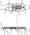
- a basic principle of the invention is in the 1a and 1b , shown.
- a pump 1 for implantation in a vessel or a heart is first introduced into the body at a suitable location.
- the pump 1 is in a first state which in Figure 1a is shown in order to subsequently be able to be functionally converted into a second state in the vessel or in the heart.
- the pump 1 For transport to the place of use, the pump 1 is mounted in its first state, for example on a guide wire of a suitable catheter or pushed over a guide wire.
- the pump 1 itself has a drive part and a delivery part FE.
- the drive part In the first state ( Fig. 1a ) the drive part is not yet functional.
- the rotor (R) is still spatially separated from the stator (S).
- the rotor is spatially separated from the stator and the stator is still shown in a collapsed state.
- the drive part only becomes functional when it is brought into the second state.
- the conveying part is connected to the drive part via a drive shaft W.
- the drive part has an electric motor, the electric motor being designed as a wet rotor.
- Wet runners are particularly advantageous because they allow a comparatively good flow and also have no problems in that the motor has to be encapsulated, so that the motor is not stuck or clogged or corroded by blood or its components, but also no risk for the bloodstream through the exchange of lubricants with the blood.
- the rotor R of the electric motor is generally arranged separately from the stator S of the electric motor in the first state.
- stator S and the rotor R are still spatially separated, and therefore the motor is not operational.
- the stator S and the rotor R are brought into one another only by the introduction of the shaft, so that the rotor R can be rotated in the stator S and then the conveying part FE can be rotated ( Fig. 1b ).
- the movement can be accomplished, for example, by shortening the shaft, pushing it in or moving it. It is particularly easy to shorten the shaft by pulling a wire (eg over a catheter). Different techniques can be used for this. Exemplary techniques include traction or thrust exerted by means of a guide wire on a catheter or by means of shape memory alloys or by spring forces, etc.
- the pump can be spring-like in the first state and when a locking device is released or when a sheathing holding in shape is released (e.g. lock or The stored force is released and leads to expansion or assembly of the individual parts.
- the rotor R can then drive the conveying part FE, in particular via a mechanical connection, as a rule a drive shaft W.
- This state is, for example, in Figure 1b shown.
- a shortening of the shaft W is given as an example in the drawings. Especially from 1a and 1b can be easily seen that the length l 1 is converted into a length l 2 in the first state, where l 1 > l 2 . Ie the shaft is shortened by ⁇ l when transitioning to the second state.
- the diameter d 1 in the area of the stator S in the second state can also be slightly expanded into a diameter d 2 depending on the configuration.
- the area of the conveyor unit can be expanded to a diameter d 3 .
- d 3 > d 2 is shown in the illustration, this need not necessarily be so, but is only intended for illustration to show that different areas in the operable second state can be expanded differently.
- the diameter d 1 in the first state is selected so that application with a catheter with a diameter of 32 French or less, in particular 24 French or less, is possible.
- the diameter can be expanded simultaneously or in succession.
- the finished pump 1 can firstly be anchored directly in or on a vessel or in the heart.
- the anchoring in the heart muscle (lat. Myocardium) MYO inside the heart is like in Figure 2 shown in relation to a possible embodiment of the invention.
- a different place of use can of course also be provided depending on the use of the pump 1 according to the invention.
- Figure 3a and 3b is another exemplary design of the pump 1 in axial cross section in a first state, which in Figure 3a is shown for shipment to the site and in a second state, which is shown in Figure 3b is shown, shown ready for operation at the place of use.
- a radial cross section similar views would result, so that a corresponding representation is not shown here.
- a pump 1 for implantation in a vessel or a heart is first introduced at a suitable point in the cardiovascular system of the body.
- the pump 1 is in a first state which in Figure 3a is shown in order to subsequently be able to be functionally converted into a second state in the vessel or in the heart.
- the pump 1 For transport to the place of use, the pump 1 is mounted in its first state, for example on a guide wire of a suitable catheter or pushed over a guide wire.
- the transport can also take place via a catheter or a lock without a guide wire.
- the pump 1 itself has a drive part and a delivery part FE.
- the drive part In the first state ( Fig. 3a ) the drive part is not yet functional.
- the drive part only becomes functional when it is brought into the second state.
- the conveying part FE is here arranged on an expandable segment which is driven by the rotor R (magnetically coupled).
- the pump 1 also has a support form SG, so that the conveying part FE does not rub against the wall of the vessel or the heart.
- Different forms of drive can be realized. For example, magnetic mounting and coupling as well as purely mechanical mounting or a magnetic-mechanical one can be provided.
- the drive part has an electric motor, the electric motor being designed as a wet rotor.
- Wet runners are particularly advantageous because they allow a comparatively good flow and also have no problems in that the motor has to be encapsulated, so that the motor is not stuck or clogged or corroded by blood or its components, but also no risk for the bloodstream through the exchange of lubricants with the blood.
- the rotor R of the electric motor is generally arranged separately from the stator S of the electric motor in the first state.
- stator S and the rotor R are initially arranged one behind the other, ie on different levels, and the motor is not operational. Only by widening in the area of the stator S does the rotor R turn and can then set the conveying part FE in rotation ( Fig. 3b ).
- the pump can be spring-like in the first state and when released (a locking device) the stored force is released and leads to a Expansion or to assemble the individual parts.
- an outer support form SG to be unfolded.
- the expansion of the sleeve-like support form SG can also be used to assemble the drive part in an operational manner, for example by means of a shortening shaft. In addition to expanding the lumen in order to provide a pump power, this expansion can also take on the function of supporting the pump 1 in the vessel or in the heart.
- the conveying part FE is magnetically coupled to the drive part.
- the conveyor part FE can also be designed such that it takes up a very small cross section in the first state.
- the conveying parts FE are arranged in two sections one behind the other.
- the first section of the conveyed part is pushed or pulled into the second section, for example by self-expansion or by corresponding other manipulations.
- the conveyor unit FE can be connected directly to the drive unit via a common shaft.
- Figure 4a and 4b is yet another exemplary design in axial cross section in a first state, which is shown in Figure 4a is shown for delivery to the site and in a second state, which is shown in Figure 4b is shown, shown ready for operation at the place of use.
- Figure 4a With regard to a radial cross section, similar views would result, so that a corresponding representation is not shown here.
- a pump 1 for implantation in a vessel or a heart is first introduced at a suitable point in the cardiovascular system of the body.
- the pump 1 is in a first state, which in Figure 4a is shown in order to subsequently be able to be functionally converted into a second state in the vessel or in the heart.
- the pump 1 For transport to the place of use, the pump 1 is mounted in its first state, for example on a guide wire of a suitable catheter or pushed over a guide wire. Alternatively, the transport can also take place via a catheter or a lock without a guide wire.
- the pump 1 itself has a drive part and a delivery part FE.
- the drive part In the first state ( Fig. 4a ) the drive part is not yet functional. The drive part only becomes functional when it is brought into the second state.
- the conveying part FE is attached to the rotor R, for example.
- the drive part has an electric motor, the electric motor being designed as a wet rotor, for example.
- Wet runners are particularly advantageous because they allow a comparatively good flow and also have no problems in that the motor has to be encapsulated, so that the motor is not stuck or clogged or corroded by blood or its components, but also no risk for the bloodstream through the exchange of lubricants with the blood.
- the rotor R of the electric motor is generally arranged separately from the stator S of the electric motor in the first state.
- stator S is divided into two parts S 1 and S 2 , for example, and the rotor R in the first state is initially located in between, ie on different levels, and the motor is not operational. It is only when the stator S is positioned in the rotor R that the rotor R becomes rotatable and can then set the conveying part FE in rotation ( Fig. 4b ).
- the two stator parts S 1 and S 2 are spatially approximated.
- the stator S (or a part thereof S 1 , S 2 ) can also be introduced into the rotor R from only one side.
- the rotor R and the stator S of the electric motor are brought into one another only when the transition to the second state occurs.
- Different techniques can be used for this. Exemplary techniques include pulling or pushing by means of a guide wire on a catheter, shape memory alloys, spring forces, etc.
- the pump can be spring-loaded in the first state and when released (a locking device) the stored force is released and leads to expansion or expansion assembling the individual parts.
- an outer support form SG unfolded and possibly the corresponding vessel or myocardium MYO to be expanded. In addition to expanding the lumen in order to provide a pump power, this expansion can also take on the function of supporting the pump 1 in the vessel or myocardium MYO.
- a shortening shaft can be provided, for example.
- this change can result from the fact that the fastening device A in 4a and 4b changes the orientation relative to the shaft and relative to the support form SG.
- the drive shaft W and the rotor R are made in one piece. This saves production costs and minimizes sources of error.
- the rotor R and the drive shaft W can, for example, also be made in several pieces, so that, for example, there is greater flexibility during transport. In this way, for example, the introduction through already heavily calcified vessels is significantly simplified, since more flexible pumps 1 can be transported, which are only assembled when in use.
- the rotor can also be broken down into two or more parts in the first state, which in turn are only joined into one another when they are transferred to the second state.
- the invention allows the use of different bearings.
- mechanical bearings can be used.
- Abrasion-resistant materials for the bearing itself or coatings of individual parts of the bearing are particularly advantageously used.
- Exemplary materials include ceramics or fine steels.
- a magnetic bearing or a magneto-mechanical bearing or a magneto-hydromechanical bearing of the drive shaft W and of the rotor R is supported.
- Magnetic bearings in particular, have proven to be advantageous, since friction can be minimized and their use in connection with wet runners is particularly advantageous.
- the magnetic bearing (as well as the magnetically assisted magneto-mechanical or magneto-hydromechanical bearing) allows the cross section available for the flow to be enlarged and wear to be minimized.
- the change in state is caused by heat input and / or an applied mechanical force and / or an external magnetic field and / or an internal one Magnetic field is caused.
- a heat input can be caused, for example, by the external coupling of an eddy current, an internally introduced heat source and / or a combination of both.
- Direct heating of (parts of) pump 1 or indirect heat transfer to (parts of) pump 1 can be provided. It is advantageous to heat only the parts that also allow a heat-induced change in condition. There is also the possibility that the heat input can take place through the body temperature. For this purpose, cooling of (at least parts of) pump 1 may be necessary before implantation.
- a mechanical force can be used by means of a guidewire or one or more further manipulation wires, as are used in catheters.
- the conveying part FE and / or the rotor R and / or the stator S and / or an outer support shape SG have a shape memory alloy or a self-expansion capability.
- These materials allow a structure that is particularly easy to manufacture, which can be moved from the first state to another state, for example by heating or cooling.
- these materials have already been tried and tested as vascular supports and have good biocompatibility.
- the pump 1 has a fixation device for fixation in the heart (e.g. myocardial muscle) and / or the vessel.
- a fixation device for fixation in the heart e.g. myocardial muscle
- Exemplary embodiments can be designed like an anchor or fish hook or rivet head. This provides a secure anchor in the vessel or in the heart.
- the pump 1 can also have an annular structure on the myocardium, e.g. can be attached using appropriate (surgical) suture material or adhesive. Without restricting generality, several different fixing devices can also be provided.
- stator S is also compressed in a first state and is expanded by the transfer into the second state.
- the conveying part FE is not functional in a first state and becomes functional due to the transfer to the second state.
- the conveyor device FE or parts thereof can also have a shape memory alloy which only leads to the conveyor device unfolding when the second state is activated (or also after activation).
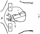
- the pump 1 can be assigned an energy supply unit EVE.
- the energy supply unit EVE is charged by induction. In this way, problems with infections caused by connecting wires which lead to the interior of the body are avoided and an intra-corporal arrangement is made possible.
- Inductive charging contributes to patient comfort, since it is now easy, e.g. during periods of rest that can charge the power supply unit without being disturbed by cables.
- an intra-corporeal energy supply unit EVE is advantageous in that the patient equipped with it enjoys greater freedom and does not have to consider the connecting cables continuously. Nevertheless, it can be provided without limitation Generality that the energy supply unit EVE is also arranged extra-corporal. This can be advantageous, for example, if the energy supply unit EVE were too large compared to the available space. This can be the case, for example, if the pump 1 is implanted in children and adolescents or if the energy requirement is so high that the battery power required for sensible operation would lead to a too large and / or too heavy energy supply unit EVE. Without restricting generality, the energy supply unit EVE can also be embodied in several (also distributed) subunits.
- This energy supply unit EVE like the pump 1, is particularly advantageously implantable in a minimally invasive manner.
- the pump 1 can also be assigned a control unit SE which supports an existing volume flow depending on a volume to be pumped.
- control unit SE can be arranged extra-corporally or intra-corporally.
- an intra-corporeal control unit SE is particularly advantageous since it minimizes the risk of infections.
- an intra-corporeal control unit SE is advantageous in that the patient equipped with it enjoys greater freedom and does not have to constantly consider the connecting cables.
- the pump 1 can be controlled manually and / or automatically.
- Manual control can e.g. targeted by the patient as soon as he notices or knows that he has or will have an increased pumping need, the pumping capacity is adjusted accordingly. Also e.g. be influenced here by appropriate medical personnel.
- the manual control can be implemented in many ways. For example, mechanical control can be provided by means of (pressure) switches, which are arranged, for example, under the skin and can be switched. Alternatively or additionally, a radio control or another electromagnetically coupled control can be provided.
- the automatic control can be designed differently. For example, a time-controlled control can take the daily routine into account, so that, for example, less or no support is provided in periods of rest.
- the automatic control can also have a hemodynamic control.
- the blood flow can be recognized by a suitable device, and if a high blood flow provide appropriate support. Suitable parameters for recognizing the blood flow can be derived, for example, from the cardiac output, the pulse and / or the blood pressure. This can be provided, for example, pulse-controlled or alternatively or additionally controlled by blood pressure or alternatively or additionally via the pump 1 itself, which functions, for example, as a flow meter when switched off.
- the automatic control can also be implemented by means of a motion control. If a certain degree of movement is detected by means of motion sensors, as are known, for example, from smartphones, navigation devices or the like, appropriate support is activated. Mixed forms of the automatic controls shown above can also be used without further ado.
- control unit SE and the energy supply unit EVE can also be designed as an integrated unit, i.e. insofar as the units were shown separately above, this separation is not necessarily to be understood physically, but only serves to illustrate the different tasks.
- Appropriate design also prevents a retrograde flow. This is done, for example, through a diaphragm DIA, as in 5a and 5b and 6a and 6b shown prevented.
- the embodiment variants shown here do not represent any limitation and other embodiments to prevent backflow, such as correspondingly shaped check valves, are also included.
- a diaphragm shown as a broken line, is integrated or built into the pump 1, the outflow tract of the pump 1 being arranged above the aortic valve as far as into the ascending aorta.
- a biological or mechanical flap can be introduced at this point, which limits or prevents the backflow.
- the pump end is designed like a diaphragm.
- the Figures 5a and 6a each represents the case in which a retrograde flow through the pump 1 is prevented, whereas the Figures 5b and 6b each represent a case in which an antegrade flow from the pump is made possible.
- the general positioning of the pump 1 in the blood flow also prevents or reduces thrombus formation on the pump 1 even when it is switched off.
- the conveyor part FE can also be designed differently. As a rule, however, the conveying part FE will have a screw shape or a propeller shape at least in sections. Without limiting the generality, the conveying part FE can also be magnetically coupled to the rotor R or the drive shaft W.
- the design of the present invention allows it to be introduced using minimally invasive techniques.
- the minimally invasive techniques For example, an apical, an atrial or a transvascular access are used.
- other components of the pump 1 can also be the subject of expandable means.
- the conveyor part as well as other components can only become operational at the place of use, e.g. in that they are expanded when the drive part is expanded or separately from it.
- different techniques or several techniques can be used simultaneously or in a specific time sequence for different elements of the pump 1 according to the invention. Exemplary techniques include pull or push using a guidewire on a catheter, shape memory alloys, spring forces, etc.
- the device is suitable for any lumen in the human or animal body.
- pumps according to the invention which can be introduced into the body by means of a 32 French (or smaller) catheter, in particular a 24 French or smaller catheter.
- a minimally invasive application can thus be achieved without difficulty, which means that even patients who otherwise could not be treated due to the high risk of surgery can be treated.
- it is now It is also possible to treat patients in whom the use of pumps was not possible or only possible to a limited extent due to the sizes of existing pumps or delivery systems (e.g. in pediatrics, neonatology or in multimorbid patients).
Landscapes
- Health & Medical Sciences (AREA)
- Engineering & Computer Science (AREA)
- Heart & Thoracic Surgery (AREA)
- General Health & Medical Sciences (AREA)
- Veterinary Medicine (AREA)
- Anesthesiology (AREA)
- Biomedical Technology (AREA)
- Hematology (AREA)
- Life Sciences & Earth Sciences (AREA)
- Animal Behavior & Ethology (AREA)
- Cardiology (AREA)
- Public Health (AREA)
- Mechanical Engineering (AREA)
- Medical Informatics (AREA)
- Computer Networks & Wireless Communication (AREA)
- Physics & Mathematics (AREA)
- Fluid Mechanics (AREA)
- Vascular Medicine (AREA)
- External Artificial Organs (AREA)
- Prostheses (AREA)
Description
- Herzinsuffizienz ist eine der häufigsten internistischen Krankheiten in den entwickelten Staaten dieser Welt. Dabei ist mit zunehmendem Alter eine vermehrte Häufigkeit der Herzinsuffizienz festzustellen.
- Im Allgemeinen wird unter einer Herzinsuffizienz das Unvermögen des Herzens verstanden, den betroffenen Organismus mit einer ausreichenden Blutzirkulation zu versorgen. Dabei ist festzustellen, dass die verminderte Blutzirkulation (auch als vermindertes Herzzeitvolumen - HZV - bezeichnet) zu einer Mangelversorgung des Gewebes mit Sauerstoff und/oder Nährstoffen führt. Symptomatisch kann sich dies in einer verminderten körperlichen Belastbarkeit und/oder vermehrter Atemnot (sogenannte Dyspnoe) als auch verstärkter Wassereinlagerung (z.B. Beinödem) manifestieren. Auf die Ursachen soll hierbei nicht weiter eingegangen werden.
- Weiterhin ist festzustellen, dass die Herzinsuffizienz auch häufig mit einem dilatierten linken Ventrikel mit reduzierter Pumpfunktion einhergeht.
- Da die Bevölkerungen zunehmend älter werden ist auch mit einer zunehmenden Anzahl von Erkrankten auszugehen. Insofern ist mit einem zunehmenden Behandlungsbedarf zu rechnen.
- Bisherige Behandlungsansätze orientieren sich am jeweiligen Stadium der Erkrankung.
- In den sogenannten leichten und mittleren Stadien (New York Heart Association NYHA I-II) wird in der Regel medikamentös therapiert. Zudem besteht die Möglichkeit der Implantierung eines Defibrillators (implantierbarer Kardioverter-Defibrillator (ICD)) oder eine Resynchronisierungs-Therapie (CRT).
- In den fortgeschrittenen als auch terminalen Stadien (New York Heart Association NYHA III-IV) ist unter Umständen eine Herztransplantation zu erwägen. Alternativ ist - insbesondere bei älteren Patienten - auch der Einsatz eines kardialen linksventrikulären Unterstützungssystems (LVAD) angezeigt. Da die Anzahl der Spenderorgane limitiert ist, ist der Einsatz eines linksventrikulären Unterstützungssystems auch als Überbrückungsmaßnahme anzutreffen.
- Bisherige LVAD-Systeme bestanden aus kontaktierenden / pulsierenden Einheiten, welche teilweise - z.B. auf Grund der Größe - außerhalb des Körpers angeordnet sind. Neuere LVAD-System, sind in der Regel intra-korporal platziert und weisen einen kontinuierlichen Fluss auf. Dabei kann mit den neueren Systemen eine Förderleistung von bis zu 8 Litern in der Minute zur Verfügung gestellt werden, wodurch auch die komplette Herzleistung ersetzt werden kann.
- Allerdings sind auch die verschiedenen neueren LVAD-Systeme dennoch aus den verschiedensten Gründen nachteilig, wie im Folgenden kurz dargestellt werden soll.
- Allen diesen Systemen ist gemein, dass sie mittels einer Operation implantiert werden müssen. Dabei ist in aller Regel der Brustkorb zu eröffnen und häufig bedarf es der Unterstützung durch eine Herz-Lungen-Maschine. D.h. es ist ein aufwändiger und risikoreicher Eingriff in Vollnarkose nötig. Zudem weisen alle diese neueren Systeme eine externe Energieeinheit und/oder eine externe Steuereinheit auf. Dabei ist die Anbindung der externen Systeme kritisch, denn entlang der drahtgebundenen Verbindung besteht die Gefahr, dass Keime eindringen. Weiterhin sind die bisherigen neueren Systeme auf eine kontinuierliche Unterstützung ausgelegt, sodass auch in Zeiten, in denen kein erhöhter Bedarf besteht, z.B. in Ruhephasen, ein hoher Blutfluss aufrecht erhalten wird. Dies wirkt sich in aller Regel negativ auf die Größe der notwendigen Energieversorgungseinheit aus und steht daher einer intra-korporalen Verlagerung der Energieversorgung entgegen. Weiterhin sind bei Patienten mit peripher arteriellem Verschluss (pAVK) und sogenannter Porzellanaorta (verkalkte Aorta) die bisherigen Systeme nur sehr eingeschränkt verwendbar.
- Die Erfindung hat sich zu einer Aufgabe gemacht, eine verbesserte Pumpe bereitzustellen, die einen oder mehrere Nachteile aus dem Stand der Technik löst.
- Die Aufgabe wird gelöst durch eine Pumpe zur Implantierung in ein Gefäß oder ein Herz, wie beansprucht, wobei die Pumpe in einem ersten Zustand in das Gefäß oder Herz eingeführt wird, um anschließend im Gefäß oder im Herz funktional in einen zweiten Zustand überführt werden zu können. Die Pumpe weist einen Antriebsteil und einen Förderteil auf, wobei der Förderteil eine Antriebswelle aufweist, wobei der Antriebsteil in dem ersten Zustand nicht funktionsfähig und durch die Überführung in den zweiten Zustand funktionsfähig wird, wobei das Antriebsteil einen Elektromotor aufweist, wobei der Elektromotor als Nassläufer ausgebildet ist, und wobei in dem ersten Zustand der Rotor des Elektromotors und der Stator des Elektromotors räumlich getrennt voneinander angeordnet sind, sodass eine Rotation des Rotors (R) durch den Stator (S) nicht möglich ist, und wobei der Rotor des Elektromotors in dem zweiten Zustand in den Stator des Elektromotors verbracht ist, wobei der Rotor im zweiten Zustand das Förderteil antreiben kann.
- Nachfolgend wird die Erfindung näher unter Bezugnahme auf die beigefügten Figuren erläutert werden. In diesen zeigt:
-
Fig. 1a eine beispielhafte schematische Darstellung in Bezug auf ein Prinzip der erfindungsgemäßen Pumpe in einem ersten Zustand in einer axialen Schnittdarstellung, -
Fig. 1b eine beispielhafte schematische Darstellung in Bezug auf ein Prinzip der erfindungsgemäßen Pumpe in einem zweiten Zustand in einer axialen Schnittdarstellung, -
Fig. 2 eine beispielhafte schematische Anordnung einer weiteren Ausführungsform einer erfindungsgemäßen Pumpe in einem zweiten Zustand im Myokard, -
Fig. 3a eine beispielhafte schematische Anordnung einer weiteren Ausführungsform einer erfindungsgemäßen Pumpe in einem ersten Zustand in einer axialen Schnittdarstellung, -
Fig. 3b eine beispielhafte schematische Anordnung einer weiteren Ausführungsform einer erfindungsgemäßen Pumpe gemäßFigur 3a in einem zweiten Zustand in einer axialen Schnittdarstellung, -
Fig. 4a eine beispielhafte schematische Anordnung einer weiteren Ausführungsform einer erfindungsgemäßen Pumpe in einem ersten Zustand in einer axialen Schnittdarstellung, -
Fig. 4b eine beispielhafte schematische Anordnung einer weiteren Ausführungsform einer erfindungsgemäßen Pumpe gemäßFigur 4a in einem zweiten Zustand in einer axialen Schnittdarstellung, -
Fig. 5a eine beispielhafte schematische Anordnung in einer axialen Schnittdarstellung in Bezug auf einen Aspekt in einem ersten (geschlossenen) Zustand, -
Fig. 5b eine beispielhafte schematische Anordnung in einer axialen Schnittdarstellung gemäßFigur 6a in Bezug auf einen Aspekt in einem zweiten (offenen) Zustand, -
Fig. 6a eine beispielhafte schematische Anordnung in einer axialen Schnittdarstellung in Bezug auf einen Aspekt in einer weiteren Ausführungsform in einem ersten (geschlossenen) Zustand, -
Fig. 6b eine beispielhafte schematische Anordnung in einer axialen Schnittdarstellung gemäßFigur 6a in Bezug auf einen Aspekt in einer weiteren Ausführungsform in einem zweiten (offenen) Zustand, -
Fig. 7 eine beispielhafte Anordnung von Einheiten einer erfindungsgemäßen Pumpe in Bezug auf einen menschlichen Körper. - Gemäß der vorliegenden Erfindung wird eine Pumpe 1 zur Implantierung in ein Gefäß oder ein Herz vorgeschlagen. Obwohl diese in unterschiedlichen Gefäßsystemen zum Einsatz kommen kann, wird nachfolgend nur Bezug auf die Implantierung im Herzen, bzw. dem Herzmuskel, oder einem Herzgefäß Bezug genommen werden, ohne dass hierdurch die Allgemeinheit der Erfindung beschränkt ist.
- Dabei erlaubt die Ausgestaltung der erfindungsgemäßen Pumpe 1 die Implantierung mittels sogenannter minimal-invasiver Technik. Beispielsweise kann die Pumpe 1 auf einen Führungsdraht montiert werden und mittels herkömmlicher Katheter-Technik an den Einsatzort vorgeschoben bzw. nur über einen Führungsdraht geschoben und dort befestigt und zum Einsatz gebracht werden. Andere Techniken der Einbringung an den Einsatzort sind hierdurch jedoch nicht ausgeschlossen, sondern sind für den Fachmann ohne weiteres ersichtlich. Beispielsweise erlaubt die erfindungsgemäße Pumpe 1 auch die Einbringung mittels Katheter oder einer Schleuse.
- Hierfür wurde die Pumpe 1 erfindungsgemäß so gestaltet, dass sie zum einen die notwendige Pumpleistung erbringen kann und dennoch so klein gestaltet werden kann, dass sie durch ein entsprechendes Gefäß (Lumen) an den Einsatzort transportiert werden kann, ohne dieses Gefäß zu verletzen.
- Durch die Gestaltung der Pumpe 1 wird es zudem ermöglicht, die Pumpe 1 apikal oder atrial in das Herz eines Patienten einzubringen.
- Dies ist besonders bei verkalkten Gefäßen, z.B. bei einer Porzellanaorta, von großem Vorteil.
- Ein Grundprinzip der Erfindung ist in den
Fig. 1a und 1b . dargestellt. - Hierbei wird eine beispielhafte schematische Darstellung in Bezug auf ein Prinzip der erfindungsgemäßen Pumpe in einem ersten Zustand zur Verbringung an den Einsatzort (
Fig.1a ) und in einem zweiten Zustand betriebsfertig am Einsatzort jeweils in einer axialen Schnittdarstellung gezeigt. - Dabei wird eine Pumpe 1 zur Implantierung in ein Gefäß oder ein Herz zunächst an einer geeigneten Stelle in den Körper eingebracht. Dabei befindet sich die Pumpe 1 in einem ersten Zustand welcher in
Figur 1a gezeigt ist, um anschließend im Gefäß oder im Herz funktional in einen zweiten Zustand überführt werden zu können. - Zum Transport an den Einsatzort wird die Pumpe 1 in ihrem ersten Zustand beispielsweise auf einen Führungsdraht eines geeigneten Katheters montiert bzw. über einen Führungsdraht geschoben. Die Pumpe 1 an sich weist einen Antriebsteil und einen Förderteil FE auf. Im ersten Zustand (
Fig. 1a ) ist der Antriebsteil noch nicht funktionsfähig. Insbesondere ist hier der Rotor (R) noch räumlich separiert vom Stator (S) angeordnet. InFig. 1a beispielsweise ist der Rotor räumlich getrennt vor dem Stator angeordnet als auch der Stator noch in einem kollabierten Zustand dargestellt. Der Antriebsteil wird erst durch die Überführung in den zweiten Zustand funktionsfähig. In denFiguren 1a und 1b ist der Förderteil über eine Antriebswelle W mit dem Antriebsteil verbunden. - Das Antriebsteil weist dabei einen Elektromotor auf, wobei der Elektromotor als Nassläufer ausgebildet ist. Nassläufer sind besonders vorteilhaft, da diese einen vergleichsweise guten Durchfluss erlauben und zudem keine Probleme dahingehend aufweisen, dass der Motor besonders gekapselt werden muss, sodass zum einen der Motor nicht durch Blut oder seine Bestandteile verklebt oder verstopft oder korrodiert wird zum anderen aber auch keine Gefährdung für den Blutkreislauf durch Austausch von Schmierstoffen mit dem Blut entstehen kann.
- Zum Transport ist in dem ersten Zustand der Rotor R des Elektromotors in aller Regel getrennt vom Stator S des Elektromotors angeordnet.
- In der
Figur 1a ist der Stator S und der Rotor R noch räumlich separiert, und daher ist der Motor nicht betriebsfähig. Erst durch die Einbringung der Welle wird der Stator S und der Rotor R ineinander verbracht, sodass der der Rotor R im Stator S drehbar wird und dann das Förderteil FE in Rotation versetzen kann (Fig. 1b ). - Das Verbringen kann z.B. durch ein Verkürzen der Welle, ein Einschieben oder Verschieben bewerkstelligt werden. Besonders einfach ist es ein Verkürzen der Welle durch ziehen eines Drahtes (z.B. über einen Katheter) zu bewerkstelligen. Hierzu können unterschiedliche Techniken zum Einsatz kommen. Beispielhafte Techniken umfassen Zug oder Schub ausgeübt mittels eines Führungsdrahtes an einem Katheter oder mittels Formgedächtnislegierungen oder durch Federkräfte, etc. So kann z.B. die Pumpe im ersten Zustand federartig gespannt sein und bei Lösen einer Verriegelungseinrichtung oder bei Freisetzen einer in Form haltenden Ummantelung (z.B. Schleuse oder Katheter) wird die gespeicherte Kraft frei und führt zu einer Expansion bzw. zu einem Zusammensetzen der Einzelteile.
- Im zweiten Zustand, der am Einsatzort gegeben ist, kann der Rotor R dann das Förderteil FE insbesondere über eine mechanische Verbindung, in der Regel eine Antriebswelle W, antreiben. Dieser Zustand ist beispielsweise in
Figur 1b gezeigt. - Eine Verkürzung der Welle W ist beispielhaft in den Zeichnungen angeben. Insbesondere aus
Fig. 1a und 1b kann ohne weiteres ersehen werden, dass die Länge l1 im ersten Zustand in eine Länge l2 überführt wird, wobei l1>l2 ist. D.h. die Welle wird um Δl beim Übergang in den zweiten Zustand verkürzt. - Dabei kann zudem der Durchmesser d1 im Bereich des Stators S im zweiten Zustand je nach Ausgestaltung leicht in einen Durchmess d2 ausgeweitet sein. Zudem kann der Bereich der Fördereinheit auf einen Durchmesser d3 ausgeweitet sein. Obwohl in der Darstellung d3>d2 dargestellt ist, muss dies nicht notwendigerweise so sein, sondern ist nur zur Illustration gedacht, um aufzuzeigen, dass unterschiedliche Bereiche im betriebsfähigem zweiten Zustand unterschiedlich ausgeweitet sein können. In aller Regel ist der Durchmesser d1 im ersten Zustand so gewählt, dass eine Applikation mit einem Katheter mit einem Durchmesser von 32 French oder weniger, insbesondere von 24 French oder weniger, möglich ist. Die Ausweitung der Durchmesser kann gleichzeitig oder hintereinander erfolgen.
- Wie bereits angedeutet, kann die fertige Pumpe 1 zum einen unmittelbar in oder an einem Gefäß bzw. im Herz verankert werden. So ist z.B. die Verankerung im Herzmuskel (lat. Myocardium) MYO innerhalb des Herzens wie in
Figur 2 in Bezug auf eine mögliche Ausführungsform der Erfindung gezeigt. Ohne Beschränkung der Allgemeinheit kann natürlich auch ein anderer Einsatzort je nach Verwendung der erfindungsgemäßen Pumpe 1 vorgesehen sein. - In
Figur 3a und 3b ist eine weitere beispielhafte Gestaltung der Pumpe 1 in axialem Querschnitt in einem ersten Zustand, welcher inFigur 3a gezeigt ist, zur Verbringung an den Einsatzort und in einem zweiten Zustand, welche inFigur 3b gezeigt ist, betriebsfertig am Einsatzort gezeigt. In Bezug auf einen radialen Querschnitt ergäben sich ähnliche Ansichten, sodass hier auf eine entsprechende Wiedergabe verzichtet wird. - Dabei wird eine Pumpe 1 zur Implantierung in ein Gefäß oder ein Herz zunächst an einer geeigneten Stelle in das Herz-Kreislauf-System des Körpers eingebracht. Dabei befindet sich die Pumpe 1 in einem ersten Zustand welcher in
Figur 3a gezeigt ist, um anschließend im Gefäß oder im Herz funktional in einen zweiten Zustand überführt werden zu können. - Zum Transport an den Einsatzort wird die Pumpe 1 in ihrem ersten Zustand beispielsweise auf einen Führungsdraht eines geeigneten Katheters montiert bzw. über einen Führungsdraht geschoben.
- Alternativ kann der Transport auch über einen Katheter oder eine Schleuse ohne Führungsdraht erfolgen. Die Pumpe 1 an sich weist einen Antriebsteil und einen Förderteil FE auf. Im ersten Zustand (
Fig. 3a ) ist der Antriebsteil noch nicht funktionsfähig. Der Antriebsteil wird erst durch die Überführung in den zweiten Zustand funktionsfähig. Der Förderteil FE ist hier auf einem aufdehnbaren Segmenten angeordnet, die vom Rotor R (magnetisch gekoppelt) angetrieben werden. Hierzu weist die Pumpe 1 weiterhin eine Stützform SG auf, sodass das Förderteil FE nicht an der Wand des Gefäßes oder des Herzens reibt. Dabei können unterschiedliche Formen des Antriebes realisiert werden. So kann z.B. eine magnetische Lagerung und Kopplung als auch eine rein mechanische Lagerung oder eine magnetisch-mechanische vorgesehen werden. - Das Antriebsteil weist dabei einen Elektromotor auf, wobei der Elektromotor als Nassläufer ausgebildet ist. Nassläufer sind besonders vorteilhaft, da diese einen vergleichsweise guten Durchfluss erlauben und zudem keine Probleme dahingehend aufweisen, dass der Motor besonders gekapselt werden muss, sodass zum einen der Motor nicht durch Blut oder seine Bestandteile verklebt oder verstopft oder korrodiert wird zum anderen aber auch keine Gefährdung für den Blutkreislauf durch Austausch von Schmierstoffen mit dem Blut entstehen kann.
- Zum Transport ist in dem ersten Zustand der Rotor R des Elektromotors in aller Regel getrennt vom Stator S des Elektromotors angeordnet.
- In der
Figuren 3a ist der Stator S und der Rotor R im ersten Zustand zunächst hintereinanderliegend, d.h. auf unterschiedlichen Ebenen, angeordnet und der Motor ist nicht betriebsfähig. Erst durch die Aufweitung im Bereich des Stators S wird der Rotor R drehbar und kann dann das Förderteil FE in Rotation versetzen (Fig. 3b ). - Erst in dem zweiten Zustand am Einsatzort wird der Rotor R des Elektromotors in den Stator S des Elektromotors verbracht. Hierzu können unterschiedliche Techniken zum Einsatz kommen. Beispielhafte Techniken umfassen Zug oder Schub ausgeübt mittels eines Führungsdrahtes an einem Katheter oder mittels Formgedächtnislegierungen, oder durch Federkräfte, etc. So kann z.B. die Pumpe im ersten Zustand federartig gespannt sein und bei Lösen (einer Verriegelungseinrichtung) wird die gespeicherte Kraft frei und führt zu einer Expansion bzw. zu einem Zusammensetzen der Einzelteile. Dabei kann wie in der
Figur 3b im Vergleich zu derFigur 3a gezeigt eine äußere Stützform SG entfaltet werden. So kann z.B. durch die Expansion der hüllenartigen Stützform SG auch dazu genutzt werden das Antriebsteil betriebsfähig zusammenzusetzen, z.B. durch eine sich verkürzende Welle. Diese Aufdehnung kann dabei neben der Erweiterung des Lumens, um eine Pumpleistung zur Verfügung zu stellen, auch die Funktion einer Abstützung der Pumpe 1 im Gefäß oder im Herzen übernehmen. - Im zweiten Zustand, der am Einsatzort gegeben ist, kann der Rotor R dann das Förderteil FE über die Antriebswelle W antreiben. Dieser Zustand ist in
Figur 3b gezeigt. - In der Ausführungsform der
Figur 3a und 3b ist das Förderteil FE magnetisch an das Antriebsteil gekoppelt. Hierdurch kann auch das Förderteil FE so gestaltet werden, dass es im ersten Zustand einen sehr geringen Querschnitt einnimmt. Dabei ist z.B. im ersten Zustand das Förderteile FE in zwei Abschnitten hintereinander liegend angeordnet. Im zweiten Zustand wird z.B. durch Selbstexpansion oder durch entsprechende andere Manipulationen der erste Abschnitt des Förderteils in den zweiten Abschnitt hingeschoben oder hineingezogen. Alternativ kann die Fördereinheit FE direkt über eine gemeinsame Welle mit der Antriebseinheit verbunden sein. - In
Figur 4a und 4b ist hierzu noch eine weitere beispielhafte Gestaltung in axialem Querschnitt in einem ersten Zustand, welcher inFigur 4a gezeigt ist, zur Verbringung an den Einsatzort und in einem zweiten Zustand, welcher inFigur 4b gezeigt ist, betriebsfertig am Einsatzort gezeigt. In Bezug auf einen radialen Querschnitt ergäben sich ähnliche Ansichten, sodass hier auf eine entsprechende Wiedergabe verzichtet wird. - Dabei wird eine Pumpe 1 zur Implantierung in ein Gefäß oder ein Herz zunächst an einer geeigneten Stelle in das Herz-Kreislauf-System des Körpers eingebracht. Dabei befindet sich die Pumpe 1 in einem ersten Zustand, welcher in
Figur 4a gezeigt ist, um anschließend im Gefäß oder im Herz funktional in einen zweiten Zustand überführt werden zu können. - Zum Transport an den Einsatzort wird die Pumpe 1 in ihrem ersten Zustand beispielsweise auf einen Führungsdraht eines geeigneten Katheters montiert bzw. über einen Führungsdraht geschoben. Alternativ kann der Transport auch über eine Katheter oder eine Schleuse ohne Führungsdraht erfolgen. Die Pumpe 1 an sich weist einen Antriebsteil und einen Förderteil FE auf. Im ersten Zustand (
Fig. 4a ) ist der Antriebsteil noch nicht funktionsfähig. Der Antriebsteil wird erst durch die Überführung in den zweiten Zustand funktionsfähig. In der Ausführungsform derFiguren 4a und 4b ist der Förderteil FE beispielsweise auf dem Rotor R angebracht. - Das Antriebsteil weist dabei einen Elektromotor auf, wobei der Elektromotor beispielsweise als Nassläufer ausgebildet ist. Nassläufer sind besonders vorteilhaft, da diese einen vergleichsweise guten Durchfluss erlauben und zudem keine Probleme dahingehend aufweisen, dass der Motor besonders gekapselt werden muss, sodass zum einen der Motor nicht durch Blut oder seine Bestandteile verklebt oder verstopft oder korrodiert wird zum anderen aber auch keine Gefährdung für den Blutkreislauf durch Austausch von Schmierstoffen mit dem Blut entstehen kann.
- Zum Transport ist in dem ersten Zustand der Rotor R des Elektromotors in aller Regel getrennt vom Stator S des Elektromotors angeordnet.
- In der
Figur 4a ist der Stator S beispielsweise in zwei Teile S1 und S2 geteilt und der Rotor R im ersten Zustand zunächst dazwischen liegend, d.h. auf unterschiedlichen Ebenen, angeordnet und der Motor ist nicht betriebsfähig. Erst durch die Positionierung des Stators S im Rotor R wird der Rotor R drehbar und kann dann das Förderteil FE in Rotation versetzen (Fig. 4b ). Dabei werden die beiden Statorteile S1 und S2 räumlich angenähert. Alternativ kann beim Wechsel von dem ersten Zustand in den zweiten Zustand auch nur von einer Seite der Stator S (oder ein Teil davon S1, S2) in den Rotor R eingebracht werden. - Erst beim Übergang in den zweiten Zustand am Einsatzort werden Rotor R und Stator S des Elektromotors ineinander verbracht. Hierzu können unterschiedliche Techniken zum Einsatz kommen. Beispielhafte Techniken umfassen Zug oder Schub mittels eines Führungsdrahtes an einem Katheter, Formgedächtnislegierungen, Federkräfte, etc. So kann z.B. die Pumpe im ersten Zustand federartig gespannt sein und bei Lösen (einer Verriegelungseinrichtung) wird die gespeicherte Kraft frei und führt zu einer Expansion bzw. zu einem Zusammensetzen der Einzelteile. Dabei kann wie in der
Figur 1b im Vergleich zu derFigur 1a gezeigt eine äußere Stützform SG entfaltet und eventuell das entsprechende Gefäß oder Myokard MYO aufgedehnt werden. Diese Aufdehnung kann dabei neben der Erweiterung des Lumens, um eine Pumpleistung zur Verfügung zu stellen, auch die Funktion einer Abstützung der Pumpe 1 im Gefäß oder Myokard MYO übernehmen. - Im zweiten Zustand, der am Einsatzort gegeben ist, kann der Rotor R dann das Förderteil FE antreiben. Dieser Zustand ist in
Figur 4b gezeigt. - Um vom ersten in den zweiten Zustand zu gelangen, kann beispielsweise eine sich verkürzende Welle vorgesehen sein. Beispielsweise kann diese Änderung sich dadurch ergeben, dass die Befestigungseinrichtung A in
Fig. 4a und 4b relativ zur Welle als auch relativ zur Stützform SG die Ausrichtung ändert. - In einer besonders einfachen Ausgestaltung ist zudem vorgesehen, dass die Antriebswelle W und der Rotor R einstückig ausgeführt sind. Hierdurch können Produktionskosten eingespart werden und Fehlerquellen minimiert werden. Auf der anderen Seite können der Rotor R und die Antriebswelle W beispielsweise auch mehrstückig ausgebildet sein, sodass z.B. eine höhere Flexibilität beim Transport gegeben ist. Hierdurch wird z.B. die Einbringung durch bereits stark verkalkte Gefäße deutlich vereinfacht, da so flexiblere Pumpen 1 transportiert werden können, die erst bei Einsatz zusammengesetzt werden.
- In einer alternativen Ausführung kann auch der Rotor im ersten Zustand in zwei oder mehr Teile zerlegt sein, die wiederum erst bei Überführung in den zweiten Zustand ineinander gefügt werden.
- Ohne Beschränkung der Allgemeinheit erlaubt die Erfindung, die Verwendung unterschiedlicher Lager. Beispielsweise können mechanische Lagerungen zum Einsatz kommen. Dabei werden besonders vorteilhaft abriebsbeständige Materialien für das Lager an sich oder aber Beschichtungen einzelner Teile der Lager verwendet. Beispielhafte Materialien weisen Keramik oder edle Stähle auf. Insbesondere wird jedoch eine magnetische Lagerung oder eine magneto-mechanische Lagerung oder eine magneto-hydromechanische Lagerung der Antriebswelle W als auch des Rotors R unterstützt. Insbesondere magnetische Lagerungen erweisen sich als vorteilhaft, da bei diesen die Reibung minimiert werden kann und deren Verwendung in Zusammenhang mit Nassläufern besonders vorteilhaft ist. Insbesondere erlaubt die magnetische Lagerung (als auch die magnetisch unterstützte magneto-mechanische bzw. magneto-hydromechanische Lagerung), dass der für den Durchfluss zur Verfügung stehende Querschnitt vergrößert wird als auch Verschleiß minimiert wird. Dies wirkt sich vorteilhaft auf die Förderleistung und/oder auf den Energieverbrauch aus. Beispielsweise kann mit der Anordnung aus
Figur 4a und 4b besonders einfach eine axiale magnetische Lagerung bereitgestellt werden, während mit den Anordnungen aus denFiguren 2 und3 besonders einfach radiale magnetische Lagerungen hergestellt werden können. Da die Figuren nur Prinzipien darstellen, können auch Mischformen aus radialen und axialen Lagerungen realisiert werden. - Um die Einbringung der erfindungsgemäßen Pumpe 1 und die Verbringung von dem ersten Zustand in den zweiten Zustand zu ermöglichen, kann z.B. vorgesehen sein, dass die Zustandsänderung durch einen Wärmeeintrag und/oder eine ausgeübte mechanische Kraft und/oder ein äußeres Magnetfeld und/oder ein inneres Magnetfeld hervorgerufen wird. Ein Wärmeeintrag kann z.B. durch die äußere Einkoppelung eines Wirbelstromes, eine intern eingebrachte Wärmequelle und/oder eine Kombination von beidem hervorgerufen werden. Dabei kann zum einen direkte Erwärmung von (Teilen der) Pumpe 1 oder eine indirekte Wärmeübertragung auf (Teile der) Pumpe 1 vorgesehen sein. Dabei ist es von Vorteil nur die Teile zu Erwärmen, die auch eine wärmeinduzierte Zustandsänderung zulassen. Es besteht darüber hinaus die Möglichkeit, dass der Wärmeeintrag durch die Körpertemperatur erfolgen kann. Hierzu ist gegebenenfalls vor Implantation eine Kühlung von (zumindest Teilen der) Pumpe 1 erforderlich. Alternativ oder Zusätzlich kann eine mechanische Kraft mittels eines Führungsdrahtes oder einem oder mehrerer weiterer Manipulationsdrähte, wie sie in Katheter Verwendung finden, benutzt werden.
- Insbesondere ist es vorteilhaft, wenn das Förderteil FE und/oder der Rotor R und/oder der Stator S und/oder ein äußere Stützform SG eine Formgedächtnislegierung bzw. eine Selbstexpansionsfähigkeit aufweisen. Diese Materialien erlauben eine besonders einfach herstellbare Struktur, die sich beispielsweise durch Erwärmung oder Abkühlung, von dem ersten Zustand in einen anderen Zustand verbringen lässt. Zudem sind diese Materialen bereits als Gefäßstützen erprobt und weisen eine gute Biokompatibilität auf.
- In vorteilhaften Ausführungsformen weist die Pumpe 1 eine Fixiereinrichtung zur Fixierung im Herz (z.B. Herzmuskel Myokard) und/oder dem Gefäß auf. Beispielhafte Ausführungsformen können ankerartig oder angelhakenartig oder nietenkopf ausgestalt sein. Hiermit wird eine sichere Verankerung im Gefäß oder im Herzen bereitgestellt. Alternativ kann die Pumpe 1 auch über eine ringförmige Struktur am Myokard z.B. durch entsprechendes (chirurgisches) Nahtmaterial oder Klebemittel befestigt werden. Ohne Beschränkung der Allgemeinheit können dabei auch mehrere unterschiedliche Fixiereinrichtungen vorgesehen sein.
- Um eine weitere Reduktion des Querschnittes im ersten Zustand bereitzustellen, kann zudem vorgesehen sein, dass auch der Stator S in einem ersten Zustand komprimiert ist und durch die Überführung in den zweiten Zustand expandiert wird.
- Ebenfalls um eine weitere Reduktion des Querschnittes im ersten Zustand bereitzustellen, kann zudem vorgesehen sein, dass das Förderteil FE in einem ersten Zustand nicht funktionsfähig ist und durch die Überführung in den zweiten Zustand funktionsfähig wird. Beispielsweise kann auch die Fördereinrichtung FE oder Teile hiervon eine Formgedächtnislegierung aufweisen, das erst mit Aktivierung (oder auch nach Aktivierung) des zweiten Zustandes zu einem Entfalten der Fördereinrichtung führt.
- Wie in
Figur 7 gezeigt kann der Pumpe 1 eine Energieversorgungseinheit EVE zugeordnet sein. - In vorteilhaften Ausführungsformen wird die Energieversorgungseinheit EVE durch Induktion geladen. Hierdurch werden Probleme mit Infektionen durch Anschlussdrähte, welche in das Körperinnere führen vermieden und es wird eine intra-korporale Anordnung ermöglicht werden.
- Eine induktive Aufladung trägt zum Patientenkomfort bei, da diese nun ohne großen Aufwand, z.B. in Ruhephasen, die Energieversorgungseinheit aufladen können, ohne durch Kabel gestört zu sein.
- Weiterhin ist eine intra-korporale Energieversorgungseinheit EVE insofern vorteilhaft, weil der damit ausgestattete Patient einen größeren Freiraum genießt und nicht kontinuierlich auf die Verbindungskabel Rücksicht nehmen muss. Dennoch kann vorgesehen sein, ohne Einschränkung der Allgemeinheit dass die Energieversorgungseinheit EVE auch extra-korporal angeordnet ist. Dies kann z.B. dann vorteilhaft sein, wenn die Energieversorgungseinheit EVE zu groß im Vergleich zum verfügbaren Raum wäre. Dies kann z.B. dann der Fall sein, wenn die Pumpe 1 bei Kindern und Jugendlichen implantiert wird oder aber der Energiebedarf so hoch ist, dass die notwendige Akkuleistung für eine sinnvollen Betrieb zu einer zu großen und/oder zu schwere Energieversorgungseinheit EVE führen würde. Ohne Beschränkung der Allgemeinheit, kann die Energieversorgungseinheit EVE auch in mehreren (auch verteilt angeordneten) Teileinheiten verkörpert sein.
- Besonders vorteilhaft ist diese Energieversorgungseinheit EVE ebenso wie die Pumpe 1 minimalinvasiv implantierbar.
- In Ausführungsformen der Erfindung kann zudem der Pumpe 1 eine Steuereinheit SE zugeordnet sein, welche anhängig von einem zu fördernden Volumen, einen vorhandenen Volumenstrom unterstützt.
- Ohne Beschränkung der Allgemeinheit kann die Steuereinheit SE extra-korporal oder intra-korporal angeordnet ist. Besonders vorteilhaft ist jedoch eine intra-korporale Steuereinheit SE, da diese die Gefahr von Infektionen minimiert. Weiterhin ist eine intra-korporale Steuereinheit SE insofern vorteilhaft, weil der damit ausgestattete Patient einen größeren Freiraum genießt und nicht ständig auf die Verbindungskabel Rücksicht nehmen muss.
- Alternative oder zusätzlich kann zudem vorgesehen sein, dass die Pumpe 1 manuell und/oder automatisch gesteuert werden kann. Durch eine manuelle Steuerung kann z.B. gezielt durch den Patienten sobald er merkt oder weiß, dass er einen erhöhten Pumpbedarf hat oder haben wird, die Pumpleistung entsprechend angepasst werden. Auch kann z.B. durch entsprechendes medizinisches Personal hier Einfluss genommen werden. Die manuelle Steuerung kann dabei in vielerlei Gestalt realisiert sein. Beispielsweise kann eine mechanische Steuerung mittels (Druck-) Schaltern, welche beispielsweise unter der Haut tast- und schaltbar angeordnet sind, bereitgestellt erfolgen. Alternativ oder zusätzlich kann eine Funksteuerung oder eine andere elektromagnetisch gekoppelte Steuerung vorgesehen sein.
- Die automatische Steuerung kann dabei unterschiedlich ausgestaltet sein. Beispielsweise kann eine zeitgesteuerte Steuerung den Tagesablauf berücksichtigen, sodass z.B. in Ruheperioden eine geringere oder gar keine Unterstützung zur Verfügung gestellt wird. In anderen Beispielen kann die automatische Steuerung auch eine hämodynamische Steuerung aufweisen. Beispielsweise kann durch eine geeignete Einrichtung der Blutfluss erkannt werden, und wenn ein hoher Blutfluss abgerufen wird, eine entsprechende Unterstützung bereitstellen. Geeignete Parameter zur Erkennung des Blutflusses können z.B. aus dem Herzzeitvolumen, dem Puls und/oder dem Blutdruck abgeleitet werden. Dies kann z.B. Pulsgesteuert oder alternativ oder zusätzlich Blutdruckgesteuert oder aber alternativ oder zusätzlich über die Pumpe 1 selbst, welche z.B. im ausgeschalteten Zustand als Durchflussmesser fungiert, bereitgestellt werden. Weiterhin kann die automatische Steuerung auch mittels einer Bewegungssteuerung realisiert werden. Wird ein gewisses Maß an Bewegung mittels Bewegungssensoren, wie sie z.B. aus Smartphones, Navigationsgeräten oder dergleichen bekannt sind, erkannt, so wird eine entsprechende Unterstützung aktiviert. Ohne weiteres können auch Mischformen der oben aufgezeigten automatischen Steuerungen zum Einsatz kommen.
- Somit wird es ermöglicht die Pumpe 1 nur dann zu aktivieren, wenn ein entsprechend erhöhtes Herzzeitvolumen benötigt wird. Diese Aktivierbarkeit nach Notwendigkeit erlaubt es den Energieverbrauch zu minimieren und erlaubt so eine vorteilhafte Ausgestaltung mit intra-korporaler Steuereinheit SE und/oder intra-korporaler Energieversorgungseinheit EVE, welche eine deutliche Verbesserung der Lebensqualität der Patienten darstellt.
- Ohne weiteres können die Steuereinheit SE und die Energieversorgungseinheit EVE auch als eine integrierte Einheit ausgeführt sein, d.h. soweit vorstehend die Einheiten getrennt dargestellt wurden, ist diese Trennung nicht notwendigerweise physikalisch zu verstehen sondern dient lediglich zur Illustration der unterschiedlichen Aufgaben.
- Durch eine entsprechende Gestaltung wird zudem ein retrograder Fluss verhindert. Dies wird z.B. durch ein Diaphragma DIA, wie in
Fig. 5a und 5b bzw. 6a und 6b gezeigt verhindert. Dabei stellen diese gezeigten Ausführungsvarianten keine Limitierung dar und andere Ausführungsformen, um einen Rückfluss zu verhindern, wie entsprechend geformte Rückschlagventile, sind ebenso umfasst. InFig. 5a und 5b ist beispielhaft für eine Einrichtung zur Verhinderung eines Rückflusses ein als gestrichelte Linie dargestelltes Diaphragma in die Pumpe 1 integriert bzw. angebaut, wobei hier der Ausflusstrakt der Pumpe 1 über der Aortenklappe bis in die Aorta ascendens AO angeordnet ist. Alternativ kann an dieser Stelle auch eine biologische oder mechanische Klappe eingebracht sein, die den Rückfluss einschränkt oder unterbindet. InFig. 5a und 5b ist das Pumpenende Diaphragma-artig ausgeführt. Dabei stellen dieFiguren 5a und6a jeweils den Fall dar, in dem ein retrograder Fluss durch die Pumpe 1 verhindert wird, wohingegen dieFiguren 5b und6b jeweils einen Fall darstellen, in dem ein antegrader Durchfluss aus der Pumpe ermöglicht wird. - Durch die generelle Positionierung der Pumpe 1 im Blutstrom wird zudem eine Thrombenbildung an der Pumpe 1 selbst im ausgeschalteten Zustand verhindert oder verringert.
- Auch das Förderteil FE kann unterschiedlich ausgestaltet sein. In aller Regel wird jedoch das Förderteil FE zumindest abschnittsweise eine Schraubenform oder eine Propellerform aufweisen. Ohne Beschränkung der Allgemeinheit kann das Förderteil FE auch magnetisch mit dem Rotor R bzw. der Antriebswelle W gekoppelt sein.
- Die vorliegende Erfindung erlaubt durch ihre Gestaltung die Einbringung mittels minimalinvasiver Techniken. Durch die Bereitstellung einer am Einsatzort in Betrieb zu setzenden Antriebsteil wird diese soweit transportfähig in ihrem radialen Querschnitt verkleinert, dass mittels der minimalinvasiver Techniken an den Einsatzort verbracht werden kann. So kann z.B. ein apikaler, ein atrialer oder eine transvaskulärer Zugang Verwendung finden.
- Ohne Beschränkung der Allgemeinheit können auch weitere Bestandteile der Pumpe 1 Gegenstand von expandierbaren Mitteln sein. Beispielsweise können auch das Förderteil als auch weitere Bestandteile erst am Einsatzort betriebsfähig werden, z.B. dadurch, dass sie beim expandieren des Antriebsteils oder getrennt hiervon expandiert werden. Hierzu können für unterschiedliche Elemente der erfindungsgemäßen Pumpe 1 unterschiedliche Techniken oder aber mehrere Techniken gleichzeitig oder in bestimmter zeitlicher Folge verwendet werden. Beispielhafte Techniken umfassen Zug oder Schub mittels eines Führungsdrahtes an einem Katheter, Formgedächtnislegierungen, Federkräfte, etc.
- Soweit vorstehend Bezug auf bestimmte Organe, wie z.B. das Herz oder den Herzmuskel (Myokard) genommen wurde, ist dies lediglich beispielhaft. Im Prinzip ist die Vorrichtung für jegliches Lumen im menschlichen oder tierischen Körper geeignet.
- Aufgrund der Erfindung ist es insbesondere möglich erfindungsgemäße Pumpen bereitzustellen, die mittels eines 32 French (oder kleiner) Katheters, insbesondere eines 24 French oder kleiner Katheters in den Körper eingeführt werden können. Somit kann ohne weiteres eine minimal-invasive Applikation erreicht werden, wodurch auch Patienten behandelt werden können, die ansonsten auf Grund des hohen Risikos einer Operation nicht behandelt werden konnten. Zudem ist es nunmehr u.a. auch möglich Patienten zu behandeln, bei denen aufgrund der Größen bisheriger Pumpen oder Zuführungssysteme eine Verwendung von Pumpen nicht oder nur eingeschränkt möglich war (z.B. in der Pädiatrie, Neonatologie oder bei multimorbiden Patienten).
Claims (21)
- Pumpe (1) zur Implantierung in ein Gefäß oder ein Herz, wobei die Pumpe (1) in einem ersten Zustand in das Gefäß oder das Herz eingeführt werden kann, um anschließend im Gefäß oder im Herz funktional in einen zweiten Zustand überführt werden zu können, aufweisend• einen Antriebsteil und• einen Förderteil (FE),• wobei der Antriebsteil in dem ersten Zustand nicht funktionsfähig und durch die Überführung in den zweiten Zustand funktionsfähig wird,• wobei das Antriebsteil einen Elektromotor aufweist,• wobei der Elektromotor als Nassläufer ausgebildet ist, und• wobei in dem ersten Zustand der Rotor (R) des Elektromotors und der Stator (S) des Elektromotors räumlich getrennt voneinander angeordnet sind, sodass eine Rotation des Rotors (R) durch den Stator (S) nicht möglich ist, und wobei der Rotor (R) des Elektromotors in dem zweiten Zustand in den Stator (S) des Elektromotors verbracht ist, wobei der Rotor (R) im zweiten Zustand das Förderteil (FE) antreiben kann,• wobei der Förderteil eine Antriebswelle (W) aufweist.
- Pumpe (1) nach Anspruch 1, wobei die Antriebswelle (W) und der Rotor (R) einstückig ausgeführt sind.
- Pumpe (1) nach Anspruch 2, dadurch gekennzeichnet, dass die Antriebswelle (W) als sich beim Übergang vom ersten Zustand in den zweiten Zustand sich verkürzende Welle ausgelegt ist, die das Verbringen des Rotors (R) in den Stator (S) ermöglicht.
- Pumpe (1) nach Anspruch 2 oder 3, dadurch gekennzeichnet, dass die Antriebswelle (W) magnetisch oder mechanisch oder magneto-mechanisch oder magneto-hydromechanische gelagert ist.
- Pumpe (1) nach einem der vorhergehenden Ansprüche, dadurch gekennzeichnet, dass der Rotor (R) magnetisch oder mechanisch oder magneto-mechanisch oder magneto-hydromechanische gelagert ist.
- Pumpe (1) nach einem der vorhergehenden Ansprüche, dadurch gekennzeichnet, dass die Zustandsänderung durch einen Wärmeeintrag und/oder eine ausgeübte mechanische Kraft und/oder ein äußeres Magnetfeld und/oder ein inneres Magnetfeld und/oder eine Selbstexpansion hervorgerufen wird.
- Pumpe (1) nach einem der vorhergehenden Ansprüche, dadurch gekennzeichnet, dass das Förderteil (FE) und/oder der Rotor (R) und/oder der Stator (S) und/oder ein äußere Stützform (SG) ein Formgedächtnislegierung aufweisen.
- Pumpe (1) nach einem der vorhergehenden Ansprüche, dadurch gekennzeichnet, dass die Pumpe (1) eine Fixiereinrichtung zur Fixierung im Herz und/oder dem Gefäß aufweist.
- Pumpe (1) nach einem der vorhergehenden Ansprüche, dadurch gekennzeichnet, dass der Stator (S) in dem ersten Zustand komprimiert ist und durch die Überführung in den zweiten Zustand expandiert wird.
- Pumpe (1) nach einem der vorhergehenden Ansprüche, dadurch gekennzeichnet, dass das Förderteil (FE) in dem ersten Zustand nicht funktionsfähig und durch die Überführung in den zweiten Zustand funktionsfähig wird.
- Pumpe (1) nach einem der vorhergehenden Ansprüche, dadurch gekennzeichnet, dass der Pumpe (1) eine Energieversorgungseinheit (EVE) zugeordnet ist.
- Pumpe (1) nach Anspruch 11, dadurch gekennzeichnet, dass die Energieversorgungseinheit (EVE) durch Induktion geladen werden kann.
- Pumpe (1) nach Anspruch 11 oder 12, dadurch gekennzeichnet, dass die Energieversorgungseinheit (EVE) extra-korporal oder intra-korporal angeordnet sein kann.
- Pumpe (1) nach einem der vorhergehenden Ansprüche, dadurch gekennzeichnet, dass der Pumpe (1) eine Steuereinheit (SE) zugeordnet ist, welche anhängig von einem zu fördernden Volumen, einen vorhandenen Volumenstrom unterstützt.
- Pumpe (1) nach Anspruch 14, dadurch gekennzeichnet, dass die Steuereinheit (SE) extra-korporal oder intra-korporal angeordnet sein kann.
- Pumpe (1) nach Anspruch 14 oder 15, dadurch gekennzeichnet, dass die Pumpe (1) manuell und/oder automatisch gesteuert werden kann.
- Pumpe (1) nach Anspruch 16, wobei im Falle der automatischen Steuerung, die Steuerung ausgewählt ist aus einer Gruppe aufweisend zeitgesteuert, hämodynamische Steuerung, Bewegungssteuerung.
- Pumpe (1) nach einem der vorhergehenden Ansprüche, dadurch gekennzeichnet, dass das Förderteil (FE) zumindest abschnittsweise eine Schraubenform oder eine Propellerform aufweist.
- Pumpe (1) nach einem der vorhergehenden Ansprüche, dadurch gekennzeichnet, dass zumindest ein Teil der Pumpe (1) eine Beschichtung zur Reduktion von Reibung, Einwachsen, Ablagerungen aufweist.
- Pumpe (1) nach einem der vorhergehenden Ansprüche, dadurch gekennzeichnet, dass die Pumpe (1) eine Einrichtung zur Verhinderung eines Rückflusses (DIA) aufweist.
- Pumpe nach einem der vorhergehenden Ansprüche, dadurch gekennzeichnet, dass die Pumpe (1) einen Durchmesser aufweist, sodass sie durch einen Katheter mit Durchmesser French 32 oder weniger geführt werden kann.
Applications Claiming Priority (2)
| Application Number | Priority Date | Filing Date | Title |
|---|---|---|---|
| DE102014211216.8A DE102014211216A1 (de) | 2014-06-12 | 2014-06-12 | Pumpe zur Implantierung in ein Gefäß |
| PCT/EP2015/062919 WO2015189259A1 (de) | 2014-06-12 | 2015-06-10 | PUMPE ZUR IMPLANTIERUNG IN EIN GEFÄß |
Publications (2)
| Publication Number | Publication Date |
|---|---|
| EP3154604A1 EP3154604A1 (de) | 2017-04-19 |
| EP3154604B1 true EP3154604B1 (de) | 2020-01-01 |
Family
ID=53434313
Family Applications (1)
| Application Number | Title | Priority Date | Filing Date |
|---|---|---|---|
| EP15730096.3A Active EP3154604B1 (de) | 2014-06-12 | 2015-06-10 | Umpe zur implantierung in ein gefäss |
Country Status (6)
| Country | Link |
|---|---|
| US (1) | US10207038B2 (de) |
| EP (1) | EP3154604B1 (de) |
| JP (1) | JP2017517306A (de) |
| CA (1) | CA2947104C (de) |
| DE (1) | DE102014211216A1 (de) |
| WO (1) | WO2015189259A1 (de) |
Families Citing this family (42)
| Publication number | Priority date | Publication date | Assignee | Title |
|---|---|---|---|---|
| EP3528865B1 (de) | 2016-10-24 | 2024-08-07 | Heartware, Inc. | Blutpumpe mit in-situ befestigung von motorstatoren |
| EP4732889A2 (de) | 2017-06-07 | 2026-04-29 | Supira Medical, Inc. | Vorrichtungen, systeme und verfahren zur bewegung intravaskulärer flüssigkeiten |
| US11511103B2 (en) | 2017-11-13 | 2022-11-29 | Shifamed Holdings, Llc | Intravascular fluid movement devices, systems, and methods of use |
| DE102018201030B4 (de) | 2018-01-24 | 2025-10-16 | Kardion Gmbh | Magnetkuppelelement mit magnetischer Lagerungsfunktion |
| JP7410034B2 (ja) | 2018-02-01 | 2024-01-09 | シファメド・ホールディングス・エルエルシー | 血管内血液ポンプならびに使用および製造の方法 |
| US11690997B2 (en) | 2018-04-06 | 2023-07-04 | Puzzle Medical Devices Inc. | Mammalian body conduit intralumenal device and lumen wall anchor assembly, components thereof and methods of implantation and explanation thereof |
| DE102018207575A1 (de) | 2018-05-16 | 2019-11-21 | Kardion Gmbh | Magnetische Stirndreh-Kupplung zur Übertragung von Drehmomenten |
| DE102018207594A1 (de) | 2018-05-16 | 2019-11-21 | Kardion Gmbh | Rotor, Magnetkupplungsvorrichtung, Elektromotor für ein Herzunterstützungssystem, Pumpeneinheit für ein Herzunterstützungssystem sowie Verfahren zum Herstellen eines Rotors |
| DE102018207611A1 (de) | 2018-05-16 | 2019-11-21 | Kardion Gmbh | Rotorlagerungssystem |
| DE102018208555A1 (de) | 2018-05-30 | 2019-12-05 | Kardion Gmbh | Vorrichtung zum Verankern eines Herzunterstützungssystems in einem Blutgefäß, Verfahren zum Betreiben und Herstellverfahren zum Herstellen einer Vorrichtung und Herzunterstützungssystem |
| DE102018208541A1 (de) | 2018-05-30 | 2019-12-05 | Kardion Gmbh | Axialpumpe für ein Herzunterstützungssystem und Verfahren zum Herstellen einer Axialpumpe für ein Herzunterstützungssystem |
| DE102018208564A1 (de) | 2018-05-30 | 2019-12-05 | Kardion Gmbh | Steuerbare Einführungshülse |
| DE102018208537A1 (de) | 2018-05-30 | 2019-12-05 | Kardion Gmbh | Vorrichtung zum Anbinden eines Herzunterstützungssystems an eine Einführeinrichtung und Verfahren zum Herstellen einer Vorrichtung zum Anbinden eines Herzunterstützungssystems an eine Einführeinrichtung |
| DE102018208538A1 (de) | 2018-05-30 | 2019-12-05 | Kardion Gmbh | Intravasale Blutpumpe und Verfahren zur Herstellung von elektrischen Leiterbahnen |
| DE102018208549A1 (de) | 2018-05-30 | 2019-12-05 | Kardion Gmbh | Elektronikmodul für ein Herzunterstützungssystem und Verfahren zum Herstellen eines Elektronikmoduls für ein Herzunterstützungssystem |
| DE102018208539A1 (de) | 2018-05-30 | 2019-12-05 | Kardion Gmbh | Motorgehäusemodul zum Abdichten eines Motorraums eines Motors eines Herzunterstützungssystems und Herzunterstützungssystem und Verfahren zum Montieren eines Herzunterstützungssystems |
| DE102018208550A1 (de) | 2018-05-30 | 2019-12-05 | Kardion Gmbh | Leitungsvorrichtung zum Leiten eines Blutstroms für ein Herzunterstützungssystem, Herzunterstützungssystem und Verfahren zum Herstellen einer Leitungsvorrichtung |
| DE102018210058A1 (de) | 2018-06-21 | 2019-12-24 | Kardion Gmbh | Statorschaufelvorrichtung zur Strömungsführung eines aus einer Austrittsöffnung eines Herzunterstützungssystems ausströmenden Fluids, Herzunterstützungssystem mit Statorschaufelvorrichtung, Verfahren zum Betreiben einer Statorschaufelvorrichtung und Herstellverfahren |
| DE102018210076A1 (de) | 2018-06-21 | 2019-12-24 | Kardion Gmbh | Verfahren und Vorrichtung zum Erkennen eines Verschleißzustands eines Herzunterstützungssystems, Verfahren und Vorrichtung zum Betreiben eines Herzunterstützungssystems und Herzunterstützungssystem |
| DE102018211297A1 (de) | 2018-07-09 | 2020-01-09 | Kardion Gmbh | Herzunterstützungssystem und Verfahren zur Überwachung der Integrität einer Haltestruktur eines Herzunterstützungssystems |
| DE102018211327A1 (de) | 2018-07-10 | 2020-01-16 | Kardion Gmbh | Laufrad für ein implantierbares, vaskuläres Unterstützungssystem |
| DE102018211328A1 (de) | 2018-07-10 | 2020-01-16 | Kardion Gmbh | Laufradgehäuse für ein implantierbares, vaskuläres Unterstützungssystem |
| DE102018212153A1 (de) | 2018-07-20 | 2020-01-23 | Kardion Gmbh | Zulaufleitung für eine Pumpeneinheit eines Herzunterstützungssystems, Herzunterstützungssystem und Verfahren zum Herstellen einer Zulaufleitung für eine Pumpeneinheit eines Herzunterstützungssystems |
| WO2020028537A1 (en) | 2018-07-31 | 2020-02-06 | Shifamed Holdings, Llc | Intravascaular blood pumps and methods of use |
| AU2019320533B2 (en) | 2018-08-07 | 2024-11-21 | Kardion Gmbh | Bearing device for a cardiac support system, and method for flushing an intermediate space in a bearing device for a cardiac support system |
| WO2020073047A1 (en) | 2018-10-05 | 2020-04-09 | Shifamed Holdings, Llc | Intravascular blood pumps and methods of use |
| CN119113374A (zh) * | 2019-03-26 | 2024-12-13 | 益智医疗器械股份有限公司 | 模块化哺乳动物身体可植入流体流动影响装置和相关方法 |
| WO2021011473A1 (en) | 2019-07-12 | 2021-01-21 | Shifamed Holdings, Llc | Intravascular blood pumps and methods of manufacture and use |
| US11654275B2 (en) | 2019-07-22 | 2023-05-23 | Shifamed Holdings, Llc | Intravascular blood pumps with struts and methods of use and manufacture |
| EP4010046A4 (de) | 2019-08-07 | 2023-08-30 | Calomeni, Michael | Katheterblutpumpen und zusammenklappbare pumpengehäuse |
| WO2021062260A1 (en) | 2019-09-25 | 2021-04-01 | Shifamed Holdings, Llc | Catheter blood pumps and collapsible blood conduits |
| EP4034192B1 (de) | 2019-09-25 | 2025-12-24 | Supira Medical, Inc. | Intravaskuläre blutpumpensysteme und verfahren zur verwendung und steuerung davon |
| EP4034221B1 (de) | 2019-09-25 | 2024-11-13 | Shifamed Holdings, LLC | Katheterblutpumpen und zusammenklappbare pumpengehäuse |
| US12383723B2 (en) | 2019-10-05 | 2025-08-12 | Puzzle Medical Devices Inc. | Mammalian body implantable fluid flow influencing device |
| EP4072650A4 (de) * | 2019-12-11 | 2024-01-10 | Shifamed Holdings, LLC | Absteigende aorten- und hohlvenenblutpumpen |
| US12599758B2 (en) | 2019-12-19 | 2026-04-14 | Shifamed Holdings, Llc | Intravascular blood pumps, motors, and fluid control |
| DE102020102474A1 (de) | 2020-01-31 | 2021-08-05 | Kardion Gmbh | Pumpe zum Fördern eines Fluids und Verfahren zum Herstellen einer Pumpe |
| CA3192451A1 (en) | 2020-09-14 | 2022-03-17 | Johannes Bette | Cardiovascular support pump having an impeller with a variable flow area |
| JP2023550938A (ja) | 2020-11-20 | 2023-12-06 | カルディオン ゲーエムベーハー | ガイドワイヤ補助具付き機械的循環支持システム |
| WO2023043973A1 (en) * | 2021-09-17 | 2023-03-23 | Abiomed, Inc. | Intravascular blood pump |
| IL320366A (en) | 2022-11-01 | 2025-06-01 | Puzzle Medical Devices Inc | Missile medical devices and methods related thereto |
| KR20260021600A (ko) * | 2023-04-13 | 2026-02-13 | 아비오메드 유럽 게엠베하 | 혈액 펌프 |
Family Cites Families (20)
| Publication number | Priority date | Publication date | Assignee | Title |
|---|---|---|---|---|
| US4964864A (en) * | 1988-09-27 | 1990-10-23 | American Biomed, Inc. | Heart assist pump |
| ES2227718T3 (es) * | 1996-10-04 | 2005-04-01 | United States Surgical Corporation | Sistema de apoyo circulatorio. |
| US5964694A (en) * | 1997-04-02 | 1999-10-12 | Guidant Corporation | Method and apparatus for cardiac blood flow assistance |
| AU2003273612A1 (en) * | 2002-06-11 | 2003-12-22 | Walid Aboul-Hosn | Percutaneously introduced blood pump and related methods |
| US7699586B2 (en) * | 2004-12-03 | 2010-04-20 | Heartware, Inc. | Wide blade, axial flow pump |
| US20090112312A1 (en) * | 2007-02-26 | 2009-04-30 | Larose Jeffrey A | Intravascular ventricular assist device |
| US8489190B2 (en) * | 2007-10-08 | 2013-07-16 | Ais Gmbh Aachen Innovative Solutions | Catheter device |
| US9199020B2 (en) * | 2007-11-01 | 2015-12-01 | Abiomed, Inc. | Purge-free miniature rotary pump |
| EP2194278A1 (de) * | 2008-12-05 | 2010-06-09 | ECP Entwicklungsgesellschaft mbH | Fluidpumpe mit einem rotor |
| EP2218469B1 (de) * | 2009-02-12 | 2012-10-31 | ECP Entwicklungsgesellschaft mbH | Gehäuse für ein Funktionselement |
| EP2448613B1 (de) * | 2009-07-01 | 2019-11-06 | The Penn State Research Foundation | Blutpumpe mit expandierbarer kanüle |
| US8690749B1 (en) * | 2009-11-02 | 2014-04-08 | Anthony Nunez | Wireless compressible heart pump |
| WO2012094641A2 (en) * | 2011-01-06 | 2012-07-12 | Thoratec Corporation | Percutaneous heart pump |
| US20130138205A1 (en) * | 2011-11-28 | 2013-05-30 | MI-VAD, Inc. | Ventricular assist device and method |
| CN104185481B (zh) * | 2012-02-07 | 2017-02-22 | 赫莱达雅公司 | 血液动力学辅助设备 |
| EP2662099B1 (de) * | 2012-05-09 | 2014-09-10 | Abiomed Europe GmbH | Intravaskuläre Blutpumpe |
| US9872947B2 (en) * | 2012-05-14 | 2018-01-23 | Tc1 Llc | Sheath system for catheter pump |
| US9358329B2 (en) * | 2012-07-03 | 2016-06-07 | Thoratec Corporation | Catheter pump |
| EP2692369B1 (de) * | 2012-07-31 | 2015-04-15 | Rheinisch-Westfälische Technische Hochschule Aachen | Blutpumpenvorrichtung mit axialem Durchfluss |
| EP2860849B1 (de) | 2013-10-11 | 2016-09-14 | ECP Entwicklungsgesellschaft mbH | Komprimierbarer Motor, Implantieranordnung sowie Verfahren zum Positionieren des Motors |
-
2014
- 2014-06-12 DE DE102014211216.8A patent/DE102014211216A1/de not_active Withdrawn
-
2015
- 2015-06-10 WO PCT/EP2015/062919 patent/WO2015189259A1/de not_active Ceased
- 2015-06-10 JP JP2016565644A patent/JP2017517306A/ja active Pending
- 2015-06-10 US US15/317,763 patent/US10207038B2/en not_active Expired - Fee Related
- 2015-06-10 EP EP15730096.3A patent/EP3154604B1/de active Active
- 2015-06-10 CA CA2947104A patent/CA2947104C/en not_active Expired - Fee Related
Non-Patent Citations (1)
| Title |
|---|
| None * |
Also Published As
| Publication number | Publication date |
|---|---|
| CA2947104A1 (en) | 2015-12-17 |
| US20170119945A1 (en) | 2017-05-04 |
| WO2015189259A1 (de) | 2015-12-17 |
| US10207038B2 (en) | 2019-02-19 |
| CA2947104C (en) | 2017-05-09 |
| EP3154604A1 (de) | 2017-04-19 |
| JP2017517306A (ja) | 2017-06-29 |
| DE102014211216A1 (de) | 2015-12-17 |
Similar Documents
| Publication | Publication Date | Title |
|---|---|---|
| EP3154604B1 (de) | Umpe zur implantierung in ein gefäss | |
| US10293090B2 (en) | Percutaneous device and method for promoting movement of a bodily fluid | |
| DE69820466T2 (de) | Implantierbares herzunterstützungssystem | |
| EP1152780B1 (de) | Vorrichtung zur intravasalen herzklappenoperation | |
| DE60310258T2 (de) | Implantierbares system zur herzunterstützung | |
| US11110266B2 (en) | Transcatheter system and method for regulating flow of fluid between two anatomical compartments | |
| EP2134385B1 (de) | Vorrichtung zur unterstützung des herzens und des kreislaufs | |
| RU2682314C2 (ru) | Устройство для управляемой поддержки перемещения митрального клапана | |
| EP3010562B1 (de) | Herzunterstützungssystem | |
| DE60020224T2 (de) | Herzunterstützungssystem | |
| DE60224025T2 (de) | Künstliches herz | |
| EP3380131B1 (de) | Implantierbares fluidpumpensystem | |
| US10449274B2 (en) | System and method of facilitating connection between cannulae and a blood pump | |
| DE112017006096T5 (de) | Aortapumpenvorrichtungen | |
| DE29804046U1 (de) | Perkutan implantierbare selbstentfaltbare Axialpumpe zur temporären Herzunterstützung | |
| US20140094645A1 (en) | Methods, Systems, and Devices Relating to a Removable Percutaneous Interface Line | |
| DE2707951A1 (de) | Vorrichtung zur versorgung eines patienten mit einem pulsierenden blutfluss | |
| US20250387613A1 (en) | Membrane crossing right cardiac assisting device | |
| EP1374928B1 (de) | Blutpumpe mit einem Impeller | |
| DE112022004459T5 (de) | Intravaskuläre blutpumpe | |
| US20240198085A1 (en) | Support for assist device | |
| EP3969074B1 (de) | Intravaskulär freigesetzte blutpumpen und zugehörige vorrichtungen und systeme | |
| DE102017103350A1 (de) | Herzfunktionssystem mit einer Kunstherzvorrichtung mit redundanten Blut-Strömungspfaden sowie Verfahren zum Unterstützen der Herzfunktion und Verwendung | |
| WO2018153990A1 (de) | VORRICHTUNG UND VERFAHREN ZUR VERBINDUNG ZWEIER BLUTGEFÄßABSCHNITTE | |
| DE202007019486U1 (de) | Vorrichtung zur Unterstützung des Herzens und des Kreislaufs |
Legal Events
| Date | Code | Title | Description |
|---|---|---|---|
| STAA | Information on the status of an ep patent application or granted ep patent |
Free format text: STATUS: THE INTERNATIONAL PUBLICATION HAS BEEN MADE |
|
| PUAI | Public reference made under article 153(3) epc to a published international application that has entered the european phase |
Free format text: ORIGINAL CODE: 0009012 |
|
| STAA | Information on the status of an ep patent application or granted ep patent |
Free format text: STATUS: REQUEST FOR EXAMINATION WAS MADE |
|
| 17P | Request for examination filed |
Effective date: 20170109 |
|
| AK | Designated contracting states |
Kind code of ref document: A1 Designated state(s): AL AT BE BG CH CY CZ DE DK EE ES FI FR GB GR HR HU IE IS IT LI LT LU LV MC MK MT NL NO PL PT RO RS SE SI SK SM TR |
|
| AX | Request for extension of the european patent |
Extension state: BA ME |
|
| DAV | Request for validation of the european patent (deleted) | ||
| DAX | Request for extension of the european patent (deleted) | ||
| GRAP | Despatch of communication of intention to grant a patent |
Free format text: ORIGINAL CODE: EPIDOSNIGR1 |
|
| STAA | Information on the status of an ep patent application or granted ep patent |
Free format text: STATUS: GRANT OF PATENT IS INTENDED |
|
| INTG | Intention to grant announced |
Effective date: 20190802 |
|
| GRAS | Grant fee paid |
Free format text: ORIGINAL CODE: EPIDOSNIGR3 |
|
| GRAA | (expected) grant |
Free format text: ORIGINAL CODE: 0009210 |
|
| STAA | Information on the status of an ep patent application or granted ep patent |
Free format text: STATUS: THE PATENT HAS BEEN GRANTED |
|
| AK | Designated contracting states |
Kind code of ref document: B1 Designated state(s): AL AT BE BG CH CY CZ DE DK EE ES FI FR GB GR HR HU IE IS IT LI LT LU LV MC MK MT NL NO PL PT RO RS SE SI SK SM TR |
|
| REG | Reference to a national code |
Ref country code: GB Ref legal event code: FG4D Free format text: NOT ENGLISH |
|
| REG | Reference to a national code |
Ref country code: CH Ref legal event code: EP Ref country code: AT Ref legal event code: REF Ref document number: 1218969 Country of ref document: AT Kind code of ref document: T Effective date: 20200115 |
|
| REG | Reference to a national code |
Ref country code: IE Ref legal event code: FG4D Free format text: LANGUAGE OF EP DOCUMENT: GERMAN |
|
| REG | Reference to a national code |
Ref country code: DE Ref legal event code: R096 Ref document number: 502015011395 Country of ref document: DE |
|
| REG | Reference to a national code |
Ref country code: NL Ref legal event code: MP Effective date: 20200101 |
|
| REG | Reference to a national code |
Ref country code: LT Ref legal event code: MG4D |
|
| PG25 | Lapsed in a contracting state [announced via postgrant information from national office to epo] |
Ref country code: RS Free format text: LAPSE BECAUSE OF FAILURE TO SUBMIT A TRANSLATION OF THE DESCRIPTION OR TO PAY THE FEE WITHIN THE PRESCRIBED TIME-LIMIT Effective date: 20200101 Ref country code: FI Free format text: LAPSE BECAUSE OF FAILURE TO SUBMIT A TRANSLATION OF THE DESCRIPTION OR TO PAY THE FEE WITHIN THE PRESCRIBED TIME-LIMIT Effective date: 20200101 Ref country code: NO Free format text: LAPSE BECAUSE OF FAILURE TO SUBMIT A TRANSLATION OF THE DESCRIPTION OR TO PAY THE FEE WITHIN THE PRESCRIBED TIME-LIMIT Effective date: 20200401 Ref country code: LT Free format text: LAPSE BECAUSE OF FAILURE TO SUBMIT A TRANSLATION OF THE DESCRIPTION OR TO PAY THE FEE WITHIN THE PRESCRIBED TIME-LIMIT Effective date: 20200101 Ref country code: CZ Free format text: LAPSE BECAUSE OF FAILURE TO SUBMIT A TRANSLATION OF THE DESCRIPTION OR TO PAY THE FEE WITHIN THE PRESCRIBED TIME-LIMIT Effective date: 20200101 Ref country code: NL Free format text: LAPSE BECAUSE OF FAILURE TO SUBMIT A TRANSLATION OF THE DESCRIPTION OR TO PAY THE FEE WITHIN THE PRESCRIBED TIME-LIMIT Effective date: 20200101 Ref country code: PT Free format text: LAPSE BECAUSE OF FAILURE TO SUBMIT A TRANSLATION OF THE DESCRIPTION OR TO PAY THE FEE WITHIN THE PRESCRIBED TIME-LIMIT Effective date: 20200527 |
|
| PGFP | Annual fee paid to national office [announced via postgrant information from national office to epo] |
Ref country code: FR Payment date: 20200422 Year of fee payment: 6 |
|
| PG25 | Lapsed in a contracting state [announced via postgrant information from national office to epo] |
Ref country code: LV Free format text: LAPSE BECAUSE OF FAILURE TO SUBMIT A TRANSLATION OF THE DESCRIPTION OR TO PAY THE FEE WITHIN THE PRESCRIBED TIME-LIMIT Effective date: 20200101 Ref country code: IS Free format text: LAPSE BECAUSE OF FAILURE TO SUBMIT A TRANSLATION OF THE DESCRIPTION OR TO PAY THE FEE WITHIN THE PRESCRIBED TIME-LIMIT Effective date: 20200501 Ref country code: SE Free format text: LAPSE BECAUSE OF FAILURE TO SUBMIT A TRANSLATION OF THE DESCRIPTION OR TO PAY THE FEE WITHIN THE PRESCRIBED TIME-LIMIT Effective date: 20200101 Ref country code: GR Free format text: LAPSE BECAUSE OF FAILURE TO SUBMIT A TRANSLATION OF THE DESCRIPTION OR TO PAY THE FEE WITHIN THE PRESCRIBED TIME-LIMIT Effective date: 20200402 Ref country code: BG Free format text: LAPSE BECAUSE OF FAILURE TO SUBMIT A TRANSLATION OF THE DESCRIPTION OR TO PAY THE FEE WITHIN THE PRESCRIBED TIME-LIMIT Effective date: 20200401 Ref country code: HR Free format text: LAPSE BECAUSE OF FAILURE TO SUBMIT A TRANSLATION OF THE DESCRIPTION OR TO PAY THE FEE WITHIN THE PRESCRIBED TIME-LIMIT Effective date: 20200101 |
|
| PGFP | Annual fee paid to national office [announced via postgrant information from national office to epo] |
Ref country code: GB Payment date: 20200422 Year of fee payment: 6 |
|
| REG | Reference to a national code |
Ref country code: DE Ref legal event code: R097 Ref document number: 502015011395 Country of ref document: DE |
|
| PG25 | Lapsed in a contracting state [announced via postgrant information from national office to epo] |
Ref country code: SM Free format text: LAPSE BECAUSE OF FAILURE TO SUBMIT A TRANSLATION OF THE DESCRIPTION OR TO PAY THE FEE WITHIN THE PRESCRIBED TIME-LIMIT Effective date: 20200101 Ref country code: SK Free format text: LAPSE BECAUSE OF FAILURE TO SUBMIT A TRANSLATION OF THE DESCRIPTION OR TO PAY THE FEE WITHIN THE PRESCRIBED TIME-LIMIT Effective date: 20200101 Ref country code: ES Free format text: LAPSE BECAUSE OF FAILURE TO SUBMIT A TRANSLATION OF THE DESCRIPTION OR TO PAY THE FEE WITHIN THE PRESCRIBED TIME-LIMIT Effective date: 20200101 Ref country code: DK Free format text: LAPSE BECAUSE OF FAILURE TO SUBMIT A TRANSLATION OF THE DESCRIPTION OR TO PAY THE FEE WITHIN THE PRESCRIBED TIME-LIMIT Effective date: 20200101 Ref country code: RO Free format text: LAPSE BECAUSE OF FAILURE TO SUBMIT A TRANSLATION OF THE DESCRIPTION OR TO PAY THE FEE WITHIN THE PRESCRIBED TIME-LIMIT Effective date: 20200101 Ref country code: EE Free format text: LAPSE BECAUSE OF FAILURE TO SUBMIT A TRANSLATION OF THE DESCRIPTION OR TO PAY THE FEE WITHIN THE PRESCRIBED TIME-LIMIT Effective date: 20200101 |
|
| PGFP | Annual fee paid to national office [announced via postgrant information from national office to epo] |
Ref country code: DE Payment date: 20200630 Year of fee payment: 6 |
|
| PLBE | No opposition filed within time limit |
Free format text: ORIGINAL CODE: 0009261 |
|
| STAA | Information on the status of an ep patent application or granted ep patent |
Free format text: STATUS: NO OPPOSITION FILED WITHIN TIME LIMIT |
|
| REG | Reference to a national code |
Ref country code: DE Ref legal event code: R079 Ref document number: 502015011395 Country of ref document: DE Free format text: PREVIOUS MAIN CLASS: A61M0001100000 Ipc: A61M0060000000 |
|
| 26N | No opposition filed |
Effective date: 20201002 |
|
| PG25 | Lapsed in a contracting state [announced via postgrant information from national office to epo] |
Ref country code: MC Free format text: LAPSE BECAUSE OF FAILURE TO SUBMIT A TRANSLATION OF THE DESCRIPTION OR TO PAY THE FEE WITHIN THE PRESCRIBED TIME-LIMIT Effective date: 20200101 Ref country code: IT Free format text: LAPSE BECAUSE OF FAILURE TO SUBMIT A TRANSLATION OF THE DESCRIPTION OR TO PAY THE FEE WITHIN THE PRESCRIBED TIME-LIMIT Effective date: 20200101 |
|
| REG | Reference to a national code |
Ref country code: CH Ref legal event code: PL |
|
| PG25 | Lapsed in a contracting state [announced via postgrant information from national office to epo] |
Ref country code: SI Free format text: LAPSE BECAUSE OF FAILURE TO SUBMIT A TRANSLATION OF THE DESCRIPTION OR TO PAY THE FEE WITHIN THE PRESCRIBED TIME-LIMIT Effective date: 20200101 Ref country code: PL Free format text: LAPSE BECAUSE OF FAILURE TO SUBMIT A TRANSLATION OF THE DESCRIPTION OR TO PAY THE FEE WITHIN THE PRESCRIBED TIME-LIMIT Effective date: 20200101 |
|
| PG25 | Lapsed in a contracting state [announced via postgrant information from national office to epo] |
Ref country code: LU Free format text: LAPSE BECAUSE OF NON-PAYMENT OF DUE FEES Effective date: 20200610 |
|
| REG | Reference to a national code |
Ref country code: BE Ref legal event code: MM Effective date: 20200630 |
|
| PG25 | Lapsed in a contracting state [announced via postgrant information from national office to epo] |
Ref country code: IE Free format text: LAPSE BECAUSE OF NON-PAYMENT OF DUE FEES Effective date: 20200610 Ref country code: CH Free format text: LAPSE BECAUSE OF NON-PAYMENT OF DUE FEES Effective date: 20200630 Ref country code: LI Free format text: LAPSE BECAUSE OF NON-PAYMENT OF DUE FEES Effective date: 20200630 |
|
| PG25 | Lapsed in a contracting state [announced via postgrant information from national office to epo] |
Ref country code: BE Free format text: LAPSE BECAUSE OF NON-PAYMENT OF DUE FEES Effective date: 20200630 |
|
| REG | Reference to a national code |
Ref country code: AT Ref legal event code: MM01 Ref document number: 1218969 Country of ref document: AT Kind code of ref document: T Effective date: 20200610 |
|
| PG25 | Lapsed in a contracting state [announced via postgrant information from national office to epo] |
Ref country code: AT Free format text: LAPSE BECAUSE OF NON-PAYMENT OF DUE FEES Effective date: 20200610 |
|
| REG | Reference to a national code |
Ref country code: DE Ref legal event code: R119 Ref document number: 502015011395 Country of ref document: DE |
|
| GBPC | Gb: european patent ceased through non-payment of renewal fee |
Effective date: 20210610 |
|
| PG25 | Lapsed in a contracting state [announced via postgrant information from national office to epo] |
Ref country code: GB Free format text: LAPSE BECAUSE OF NON-PAYMENT OF DUE FEES Effective date: 20210610 Ref country code: DE Free format text: LAPSE BECAUSE OF NON-PAYMENT OF DUE FEES Effective date: 20220101 |
|
| PG25 | Lapsed in a contracting state [announced via postgrant information from national office to epo] |
Ref country code: TR Free format text: LAPSE BECAUSE OF FAILURE TO SUBMIT A TRANSLATION OF THE DESCRIPTION OR TO PAY THE FEE WITHIN THE PRESCRIBED TIME-LIMIT Effective date: 20200101 Ref country code: MT Free format text: LAPSE BECAUSE OF FAILURE TO SUBMIT A TRANSLATION OF THE DESCRIPTION OR TO PAY THE FEE WITHIN THE PRESCRIBED TIME-LIMIT Effective date: 20200101 Ref country code: FR Free format text: LAPSE BECAUSE OF NON-PAYMENT OF DUE FEES Effective date: 20210630 Ref country code: CY Free format text: LAPSE BECAUSE OF FAILURE TO SUBMIT A TRANSLATION OF THE DESCRIPTION OR TO PAY THE FEE WITHIN THE PRESCRIBED TIME-LIMIT Effective date: 20200101 |
|
| PG25 | Lapsed in a contracting state [announced via postgrant information from national office to epo] |
Ref country code: MK Free format text: LAPSE BECAUSE OF FAILURE TO SUBMIT A TRANSLATION OF THE DESCRIPTION OR TO PAY THE FEE WITHIN THE PRESCRIBED TIME-LIMIT Effective date: 20200101 Ref country code: AL Free format text: LAPSE BECAUSE OF FAILURE TO SUBMIT A TRANSLATION OF THE DESCRIPTION OR TO PAY THE FEE WITHIN THE PRESCRIBED TIME-LIMIT Effective date: 20200101 |