EP3155152B1 - Tissu pour blindage électromagnétique - Google Patents
Tissu pour blindage électromagnétique Download PDFInfo
- Publication number
- EP3155152B1 EP3155152B1 EP15733840.1A EP15733840A EP3155152B1 EP 3155152 B1 EP3155152 B1 EP 3155152B1 EP 15733840 A EP15733840 A EP 15733840A EP 3155152 B1 EP3155152 B1 EP 3155152B1
- Authority
- EP
- European Patent Office
- Prior art keywords
- fabric
- electromagnetic shielding
- warp yarns
- conductive
- electromagnetic
- Prior art date
- Legal status (The legal status is an assumption and is not a legal conclusion. Google has not performed a legal analysis and makes no representation as to the accuracy of the status listed.)
- Active
Links
Images



Classifications
-
- D—TEXTILES; PAPER
- D03—WEAVING
- D03D—WOVEN FABRICS; METHODS OF WEAVING; LOOMS
- D03D1/00—Woven fabrics designed to make specified articles
- D03D1/0035—Protective fabrics
- D03D1/0058—Electromagnetic radiation resistant
-
- D—TEXTILES; PAPER
- D03—WEAVING
- D03D—WOVEN FABRICS; METHODS OF WEAVING; LOOMS
- D03D13/00—Woven fabrics characterised by the special disposition of the warp or weft threads, e.g. with curved weft threads, with discontinuous warp threads, with diagonal warp or weft
-
- D—TEXTILES; PAPER
- D03—WEAVING
- D03D—WOVEN FABRICS; METHODS OF WEAVING; LOOMS
- D03D13/00—Woven fabrics characterised by the special disposition of the warp or weft threads, e.g. with curved weft threads, with discontinuous warp threads, with diagonal warp or weft
- D03D13/008—Woven fabrics characterised by the special disposition of the warp or weft threads, e.g. with curved weft threads, with discontinuous warp threads, with diagonal warp or weft characterised by weave density or surface weight
-
- D—TEXTILES; PAPER
- D03—WEAVING
- D03D—WOVEN FABRICS; METHODS OF WEAVING; LOOMS
- D03D15/00—Woven fabrics characterised by the material, structure or properties of the fibres, filaments, yarns, threads or other warp or weft elements used
- D03D15/40—Woven fabrics characterised by the material, structure or properties of the fibres, filaments, yarns, threads or other warp or weft elements used characterised by the structure of the yarns or threads
- D03D15/43—Woven fabrics characterised by the material, structure or properties of the fibres, filaments, yarns, threads or other warp or weft elements used characterised by the structure of the yarns or threads with differing diameters
-
- D—TEXTILES; PAPER
- D03—WEAVING
- D03D—WOVEN FABRICS; METHODS OF WEAVING; LOOMS
- D03D15/00—Woven fabrics characterised by the material, structure or properties of the fibres, filaments, yarns, threads or other warp or weft elements used
- D03D15/50—Woven fabrics characterised by the material, structure or properties of the fibres, filaments, yarns, threads or other warp or weft elements used characterised by the properties of the yarns or threads
- D03D15/533—Woven fabrics characterised by the material, structure or properties of the fibres, filaments, yarns, threads or other warp or weft elements used characterised by the properties of the yarns or threads antistatic; electrically conductive
-
- D—TEXTILES; PAPER
- D10—INDEXING SCHEME ASSOCIATED WITH SUBLASSES OF SECTION D, RELATING TO TEXTILES
- D10B—INDEXING SCHEME ASSOCIATED WITH SUBLASSES OF SECTION D, RELATING TO TEXTILES
- D10B2101/00—Inorganic fibres
- D10B2101/20—Metallic fibres
-
- D—TEXTILES; PAPER
- D10—INDEXING SCHEME ASSOCIATED WITH SUBLASSES OF SECTION D, RELATING TO TEXTILES
- D10B—INDEXING SCHEME ASSOCIATED WITH SUBLASSES OF SECTION D, RELATING TO TEXTILES
- D10B2321/00—Fibres made from polymers obtained by reactions only involving carbon-to-carbon unsaturated bonds
- D10B2321/04—Fibres made from polymers obtained by reactions only involving carbon-to-carbon unsaturated bonds polymers of halogenated hydrocarbons
- D10B2321/042—Fibres made from polymers obtained by reactions only involving carbon-to-carbon unsaturated bonds polymers of halogenated hydrocarbons polymers of fluorinated hydrocarbons, e.g. polytetrafluoroethene [PTFE]
-
- D—TEXTILES; PAPER
- D10—INDEXING SCHEME ASSOCIATED WITH SUBLASSES OF SECTION D, RELATING TO TEXTILES
- D10B—INDEXING SCHEME ASSOCIATED WITH SUBLASSES OF SECTION D, RELATING TO TEXTILES
- D10B2331/00—Fibres made from polymers obtained otherwise than by reactions only involving carbon-to-carbon unsaturated bonds, e.g. polycondensation products
- D10B2331/02—Fibres made from polymers obtained otherwise than by reactions only involving carbon-to-carbon unsaturated bonds, e.g. polycondensation products polyamides
-
- D—TEXTILES; PAPER
- D10—INDEXING SCHEME ASSOCIATED WITH SUBLASSES OF SECTION D, RELATING TO TEXTILES
- D10B—INDEXING SCHEME ASSOCIATED WITH SUBLASSES OF SECTION D, RELATING TO TEXTILES
- D10B2331/00—Fibres made from polymers obtained otherwise than by reactions only involving carbon-to-carbon unsaturated bonds, e.g. polycondensation products
- D10B2331/02—Fibres made from polymers obtained otherwise than by reactions only involving carbon-to-carbon unsaturated bonds, e.g. polycondensation products polyamides
- D10B2331/021—Fibres made from polymers obtained otherwise than by reactions only involving carbon-to-carbon unsaturated bonds, e.g. polycondensation products polyamides aromatic polyamides, e.g. aramides
-
- D—TEXTILES; PAPER
- D10—INDEXING SCHEME ASSOCIATED WITH SUBLASSES OF SECTION D, RELATING TO TEXTILES
- D10B—INDEXING SCHEME ASSOCIATED WITH SUBLASSES OF SECTION D, RELATING TO TEXTILES
- D10B2331/00—Fibres made from polymers obtained otherwise than by reactions only involving carbon-to-carbon unsaturated bonds, e.g. polycondensation products
- D10B2331/04—Fibres made from polymers obtained otherwise than by reactions only involving carbon-to-carbon unsaturated bonds, e.g. polycondensation products polyesters, e.g. polyethylene terephthalate [PET]
-
- D—TEXTILES; PAPER
- D10—INDEXING SCHEME ASSOCIATED WITH SUBLASSES OF SECTION D, RELATING TO TEXTILES
- D10B—INDEXING SCHEME ASSOCIATED WITH SUBLASSES OF SECTION D, RELATING TO TEXTILES
- D10B2401/00—Physical properties
- D10B2401/04—Heat-responsive characteristics
- D10B2401/041—Heat-responsive characteristics thermoplastic; thermosetting
-
- D—TEXTILES; PAPER
- D10—INDEXING SCHEME ASSOCIATED WITH SUBLASSES OF SECTION D, RELATING TO TEXTILES
- D10B—INDEXING SCHEME ASSOCIATED WITH SUBLASSES OF SECTION D, RELATING TO TEXTILES
- D10B2401/00—Physical properties
- D10B2401/16—Physical properties antistatic; conductive
Definitions
- the present invention relates to a fabric for electromagnetic shielding.
- these cables being crossed by an electric current, they emit an electromagnetic field which is disruptive for their environment. It is also appropriate that these cables are not disturbed by any electromagnetic fields. In other words, it is necessary to prevent a signal from escaping the cable and also to prevent a spurious signal from being added to the signal carried by the same cable.
- the conductive cables are integrated in an aircraft, motor vehicle or other device and, consequently, may be brought into contact with mechanical devices of the apparatus in question. During operation, vibrations may occur which cause cycles of friction between the cables and the surrounding members to be observed; these vibrations can damage the cables.
- the electric cables are protected by sheaths that provide electromagnetic shielding and mechanical protection.
- electromagnetic shielding sheath we know, for example, by the document EP 1 348 247 , an electromagnetic shielding braid that provides both electromagnetic shielding - on the order of 50/60 dB at 30/40 MHz - and high quality mechanical protection.
- sheaths There are also so-called self-resealing armor sheaths. Unlike braided sheaths, these sheaths consist of woven ribbons.
- the warp yarns comprise conductive metal strands to provide the shielding function, while the weft yarns comprise thermoformable mono filamentary strands to provide the self-holding function of the tubular-shaped sheath.
- an electromagnetic shielding fabric having an armor of weft and warp yarns and in which some weft yarns are conductive is known to EP 2233620 A2 .
- an object of the invention is to provide a light self-resealing fabric having an electromagnetic shielding efficiency close to the values of a braided tubular metal sheath, 50-60dB at 30 / 40MHz.
- the invention relates to an electromagnetic shielding fabric having a weave of intertwined weft yarns and warp yarns, characterized in that the conductive warp yarns comprise monofilament or multifilament yarns associated with metal strands and in that at least one conductor wire is inserted in a frame to create an equipotential bond perpendicular to the direction of the strings.
- the fabric comprises a plurality of conductive chain son inserted in a chain in a pitch of between 1 and 8 in the crowds.
- the fabric comprises chain conductor wires forming a protective face electromagnetic, chain son forming a mechanical protection face and chain son ensuring binding of chain conductor son forming the electromagnetic shielding face and chain son forming the mechanical protection face.
- chain conductor son forming the electromagnetic protection face are woven in a plain weave and chain son forming a mechanical protection face are woven in a plain weave.
- the invention relates to a sheath formed by the aforementioned fabric.
- the sheath comprises a conductive strip of conductive warp threads inserted by weaving into the plain weave on the mechanical protection face so that the conductive strip is covered by the opposite face on the electromagnetic side of the sheath. and constitutes a looping of the electrical circuit of the electromagnetic protection face when the sheath is closed on itself.
- the fabric 1 for electromagnetic shielding has an armor of weft son 2 and chain son 3 intertwined.
- the warp yarns 3 comprise conductive strands associated with textile fibers.
- the 3-conductor warp yarns may comprise monofilament yarns associated with metal strands.
- the metal strands can be incorporated in monofilament son by wrapping, stranding or braiding.
- the ratio of the diameters of monofilaments and metal strands in the warp yarns can be at least 2.5 mm.
- the diameter of the monofilaments is of the order of 0.25 mm and the diameter of the metal strands is of the order of 0.15 mm.
- the weft yarns 2 may be conductive yarns but, preferably, are nonconductive yarns essentially composed of thermoplastic monofilaments, for example PET; PET-FR; PBT; PMMA; PA4.6; PA6.6; PA11; PA12; PPS; PEEK; ECTFE; PVDF; ETFE FEP; PFA; PTFE so that the fabric incorporating these weft son 2 has a linear density contained.
- thermoplastic monofilaments for example PET; PET-FR; PBT; PMMA; PA4.6; PA6.6; PA11; PA12; PPS; PEEK; ECTFE; PVDF; ETFE FEP; PFA; PTFE so that the fabric incorporating these weft son 2 has a linear density contained.
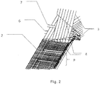
- the figure 2 shows the manner in which the first step of manufacturing the fabric according to the invention is carried out.
- a predetermined pitch P which can be, for example, 8 picks, according to the example of the figure 1 , to insert a chain wire 4 - which is therefore conductive - in the frame.
- the loom has a lower weft insertion needle 6 and an upper weft insertion needle 7; these needles will thus allow to insert into the frame composed of non-conductive son, a chain son who is conductive.
- a needle which has a profile allowing it to take according to the thread which is presented to it, the weft thread and the warp thread which is conductive.
- the fabric according to the invention is provided with a conductive thread in its weft direction, which thus forms an equipotential bond.
- the resulting fabric has an interweaving of conductive son, which is very favorable for the electromagnetic efficiency.
- the fabric After weaving, the fabric undergoes a treatment phase essentially by heating known per se to give it its shape memory property, that is to say its ability to wind on itself.
- the Figure 3 shows another embodiment of the invention in which the fabric has two faces which appear visually different so as to distinguish the functions of mechanical protection and electromagnetic protection.
- the fabric is woven according to the double weaving method with a particular binding yarn.
- the figure 3 schematically shows the weave of the fabric with the double weave. This particular method is combined with the conductive warp yarn 30 inserted in weft in the weaving of an electromagnetic shielding face.
- the figure 3 shows a loose binding that is used in this example; the conductive son of the chain are grouped in a weave weave type to form the electromagnetic shielding face, monofilament or multifilament son of the chain 31 are grouped in a weave weave type to form the mechanical protection face.
- the two armor are linked by son of chains 32 chosen monofilaments or multifilaments to form the binding.
- the binding son 32 is visible on the mechanical protection side and invisible electromagnetic protection side.
- the figure 3 shows an electromagnetic shielding measurement for a cladding composed, according to the prior art, of a fabric having (i) 8-stranded tinned copper strand of 0.10 mm and PET monofilaments of 0.25 mm and (ii) weft PET thermoplastic monofilaments 0.254 mm in diameter.
- the figure 6 shows an electromagnetic shielding measurement made with the fabric shown in FIG. Figure 1 .
- This fabric comprises (i) PET textile yarns and 0.10 mm 8-strand tinned copper strands and (ii) weft PET thermoplastic monofilaments and chain metal strands in a pitch of eight picks.
- the measurements carried out within the framework of the aforementioned standard show an attenuation of the order of 42 dB at 30 MHz and 40 dB at a frequency of 40 MHz.
- the Figure 7 shows an electromagnetic shielding measurement made with a variant of the fabric shown in FIG. Figure 1 .
- This fabric comprises (i) PET textile yarns and 0.10 mm 8-stranded tinned copper strands and (ii) weft PET thermoplastic monofilaments and chain metal strands inserted on each pick. Measurements made in the framework of the aforementioned standard show attenuation of the order of 48dB at 30MHz and 45dB for a frequency of 40 MHz.
- a metal coating on the fabric can be performed by electrochemical deposition according to known techniques.
- a thickness in the range of 0.2 ⁇ m to 1.3 ⁇ m is deposited according to the desired level of shielding attenuation.
- the Figure 8 shows an electromagnetic shielding measurement made with a variant of the fabric shown in FIG. Figure 1 , this one having received a nickel coating.
- This fabric comprises (i) PET textile yarns and 0.10 mm 8-strand tinned copper strands, (ii) weft PET thermoplastic monofilaments and chain metal strands inserted in a pitch of eight picks and (iii) ) a metallized coating electrochemically deposited on a thickness of about 0.7 microns, knowing that the coating may have a thickness of 0.2 microns to 1.3 microns.
- Measurements made within the framework of the aforementioned standard show attenuation of the order of 56 dB at 30 MHz and 55.5 dB at a frequency of 40 MHz.
- the sheath which is formed by a band of fabric closed on itself comprises a conductor strip of conducting warp threads inserted by weaving into the plain weave on the mechanical protection face. so that the conductive strip is covered by the opposite side side electromagnetic protection side of the sheath and constitutes a looping of the electrical circuit of the electromagnetic protection face when the sheath is closed on itself.
- the invention is not limited to the embodiments described for a fabric (Taffeta), for example, but it encompasses all embodiments such as Twill, Satin, Reps, Reps across ( fluted), Long Reps, Plaiting Armor (Panama) etc ...
Landscapes
- Engineering & Computer Science (AREA)
- Textile Engineering (AREA)
- Physics & Mathematics (AREA)
- Electromagnetism (AREA)
- Woven Fabrics (AREA)
- Shielding Devices Or Components To Electric Or Magnetic Fields (AREA)
Description
- La présente invention concerne un tissu pour blindage électromagnétique.
- On peut observer notamment dans le domaine général du transport que de nombreuses fonctions sont réalisées par des motorisations électriques.
- La conséquence est que l'on trouve dans de nombreux appareils tels que - de manière non limitative - : aéronefs, véhicules automobiles notamment électriques et/ou hybrides etc. des câbles qui relient des batteries à des actuateurs électriques.
- La présence de faisceaux de câbles conducteurs présente un impact à deux niveaux.
- D'une part, ces câbles étant traversés par un courant électrique, ils émettent un champ électromagnétique qui est perturbateur pour leur environnement. Il convient également que ces câbles ne soient pas perturbés par d'éventuels champs électromagnétiques. En d'autres termes, il convient d'empêcher qu'un signal ne s'échappe du câble et d'empêcher également qu'un signal parasite ne s'ajoute au signal transporté par ce même câble.
- D'autre part, les câbles conducteurs s'intègrent dans un appareil - aéronef, véhicule automobile ou autre - et, par conséquent, peuvent être amenés à être en contact avec des organes mécaniques de l'appareil en question. En cours de fonctionnement, il peut se produire des vibrations qui font que l'on observe des cycles de frottements entre les câbles et les organes qui l'environnent ; ces vibrations peuvent endommager les câbles.
- Les câbles électriques sont donc protégés par des gaines qui assurent un blindage électromagnétique et une protection mécanique.
- En matière de gaine de blindage électromagnétique, on connait, par exemple, par le document
EP 1 348 247 , une tresse de blindage électromagnétique qui assure à la fois un blindage électromagnétique - de l'ordre de 50/60 dB à 30/40 MHz - et une protection mécanique de qualité. - Cependant le principe de la tresse qui est donc fermée sur elle-même peut lui interdire certaines applications. En effet, la mise en place d'une tresse de blindage s'effectue en introduisant une extrémité du câble dans la gaine puis en la faisant glisser sur le câble.
- Ainsi, la mise en place d'une gaine sur un câble qui est en place ne peut pas se faire sans démontage de ce dernier.
- Il existe également des gaines de blindage dites auto-refermables. Contrairement aux gaines tressées, ces gaines sont constituées de rubans tissés. Les fils de chaine comprennent des brins métalliques conducteurs pour assurer la fonction de blindage, tandis que les fils de trame comprennent des brins mono filamentaires thermoformables pour assurer la fonction d'auto maintien de la gaine en forme tubulaire.
- De part leur construction ouverte, les gaines de blindage tissées auto-refermables présentent de médiocres performances. Leur efficacité généralement constatée est de l'ordre de 30 dB à 30/40 MHz soit une efficacité électromagnétique dégradée d'environ 20 à 30 dB par rapport à une gaine tressée, telle que celle décrite précédemment.
- La raison pour laquelle les gaines tissées auto-refermables conventionnelles présentent un faible pouvoir de blindage tient principalement à l'absence de liaison équipotentielle. Pour pallier cette absence, on recourt à des artifices pour créer des liaisons équipotentielles.
- Ainsi, il est connu de placer des colliers métalliques, par exemple, aux extrémités de la gaine. Il est également connu de réaliser des ligatures à intervalles réguliers par des colliers métalliques. Cela présente un coût en équipement et en temps de pose.
- D'autre part, ces gaines tissées auto-refermables peuvent être relativement lourdes, ce qui est un handicap pour ce type de gaines notamment pour des applications aéronautiques. Un tissu pour blindage électromagnétique présentant une armure de fils de trame et de fil de chaîne et dans lequel certains fils de trame sont conducteurs, est connu de
EP 2233620 A2 . Dans ce contexte technique, un but de l'invention est de proposer un tissu auto-refermable léger et présentant une efficacité de blindage électromagnétique proche des valeurs d'une gaine métallique tubulaire tressée, 50-60dB à 30/40MHz. - Ainsi, l'invention concerne un tissu pour blindage électromagnétique présentant une armure de fils de trame et de fils de chaine entrelacés, caractérisé en ce que les fils de chaine conducteurs comprennent des fils de monofilaments ou multifilaments associés à des brins métalliques et en ce que au moins un fil de chaine conducteur est inséré en trame pour créer une liaison équipotentielle perpendiculaire à la direction des fils de chaînes. De préférence, le tissu comprend plusieurs fils de chaînes conducteurs insérés en chaîne selon un pas compris entre 1 et 8 dans les foules.
- Selon une forme de réalisation préférée de l'invention, le tissu comprend des fils conducteurs de chaine formant une face de protection électromagnétique, des fils de chaine formant une face de protection mécanique et des fils de chaine assurant le liage des fils conducteurs de chaine formant la face de protection électromagnétique et des fils de chaine formant la face de protection mécanique.
- De plus, les fils conducteurs de chaine formant la face de protection électromagnétique sont tissés selon une armure toile et les fils de chaine formant une face de protection mécanique sont tissés selon une armure toile.
- Selon d'autres caractéristiques du tissu selon l'invention :
- le rapport des diamètres des monofilaments et des brins métalliques dans les fils de chaine est d'au moins 2.5.
- le diamètre des monofilaments est de l'ordre de 0.125 mm à 0.40 mm et le diamètre des brins métalliques est de l'ordre de 0.05 mm à 0.16 mm.
- les fils de trame sont constitués d'un ou plusieurs matériaux du groupe comprenant: PET ; PET-FR ; PBT ; PMMA ; PA4.6 ; PA6.6 ; PA11 ; PA12 ; PPS ; PEEK ; ECTFE ; PVDF ; ETFE FEP ; PFA ; PTFE.
- les fils de chaine associés aux brins métalliques sont constitués d'un ou plusieurs matériaux du groupe comprenant : PET ; PBT ; PMMA ; polyéthylène ; Polyamides; acryliques ; carbones ; PAN; polypropylène ; PPS ; polyimides ; PEEK ; ECTFE ; PVDF ; Fluorofibres ; fibres de verre ; fibres céramiques et minérales, fibres aramides et méta-aramides ; Cuivre nu ou revêtu étain, nickel, argent ; laiton nu ou étamé ; Aluminium, alliages d'aluminium, acier nu, acier zingué, acier cuivré étamé, acier cuivré nickelé, acier cuivré argenté, inox, inconel®, Monel®, nickel et alliages de nickel , alliages Cupro-Nickel ;
- le tissu reçoit une couche de revêtement d'un ou plusieurs éléments du groupe comprenant Cuivre, Zinc, Nickel ou Argent.
- Selon un autre aspect, l'invention concerne une gaine formée par le tissu précité.
- Dans une forme de réalisation, la gaine comprend une bande conductrice de fils de chaine conducteurs insérée par tissage dans l'armure toile sur la face de protection mécanique de sorte que la bande conductrice est recouverte par la face opposée côté face protection électromagnétique de la gaine et constitue un bouclage du circuit électrique de la face protection électromagnétique lorsque la gaine est refermée sur elle-même.
- Pour sa bonne compréhension, l'invention est décrite en référence au dessin ci-annexé représentant à titre d'exemple non limitatif plusieurs formes de réalisation d'un tissu selon l'invention.
-
Figure 1 est une vue schématique de l'armure d'un tissu selon une forme de réalisation de l'invention ; -
Figure 2 est une vue schématique du tissu au cours de tissage ; -
Figures 3 et 4 montrent un tissu en double tissage intégrant le fil de chaine pris en trame respectivement en vue schématique et en dessin d'armure ; -
Figures 5 à 8 montrent quatre mesures de blindage sur banc triaxial selon les dispositions de la norme IEC 62153-4-3 pour, respectivement, une gaine de l'art antérieur et trois gaines utilisant trois formes de réalisation de tissu selon l'invention. - Comme on peut le voir sur la
figure 2 , le tissu 1 pour blindage électromagnétique présente une armure de fils de trame 2 et de fils de chaine 3 entrelacés. - Les fils de chaine 3 comprennent des brins conducteurs associés à des fibres textiles. De manière concrète, les fils de chaine 3 conducteurs peuvent comprendre des fils de monofilaments associés à des brins métalliques. Les brins métalliques peuvent être incorporés aux fils de monofilaments par guipage, toronnage ou encore tressage.
- En pratique, le rapport des diamètres des monofilaments et des brins métalliques dans les fils de chaine peut être d'au moins 2.5 mm.
- Ainsi on peut envisager une forme d'exécution de l'invention dans laquelle le diamètre des monofilaments est de l'ordre de 0.25 mm et le diamètre des brins métalliques est de l'ordre de 0.15 mm.
- Les fils de trame 2 peuvent être des fils conducteurs mais, de préférence, sont des fils non conducteurs composés essentiellement de monofilaments thermoplastiques, par exemple PET ; PET-FR ; PBT ; PMMA ; PA4.6 ; PA6.6 ; PA11 ; PA12 ; PPS ; PEEK ; ECTFE ; PVDF ; ETFE FEP ; PFA ; PTFE de sorte que le tissu incorporant ces fils de trame 2 présente une masse linéique contenue.
- La
figure 2 fait apparaître la manière avec laquelle la première étape de fabrication du tissu selon l'invention est réalisée. - Comme le montre cette figure, il est prévu à un pas P prédéterminé qui peut être, par exemple, de 8 duites, selon l'exemple de la
figure 1 , d'insérer un fil de chaine 4 - qui est donc conducteur - dans la trame. - Dans la
figure 1 , les références numériques désignent : - 1 fil textile
- 2 fil textile
- 3 fil métallique
- 4 fil textile
- 5 fil métallique inséré en trame
- 6 fil textile
- 7 fil textile
- 8 fil métallique.
- Il est également possible d'intercaler d'autres fils conducteurs de la chaine dans la trame en les disposant sur des cadres différents et de les sélectionner sur des séquences d'une duite minimum mais en décalage de phase les unes par rapport aux autres.
- Pour cela, le métier à tisser est doté d'une aiguille inférieure d'insertion de trame 6 et d'une aiguille supérieure d'insertion de trame 7 ; ces aiguilles vont ainsi permettre d'insérer dans la trame composée de fils non conducteurs, un fils de chaine qui est conducteur.
- Selon une autre possibilité, il est possible d'utiliser une aiguille qui présente un profil lui permettant de prendre selon le fil qui lui est présenté, le fil de trame et le fil de chaine qui est conducteur.
- Ainsi, le tissu selon l'invention se trouve doté d'un fil conducteur dans son sens trame qui forme ainsi une liaison équipotentielle. Le tissu ainsi obtenu présente un entrecroisement de fils conducteurs, ce qui s'avère très favorable pour l'efficacité électromagnétique.
- Après tissage, le tissu subit une phase de traitement essentiellement par chauffage connue en soi pour lui donner sa propriété de mémoire de forme, c'est-à-dire sa capacité à s'enrouler sur lui-même.
- La
Figure 3 montre une autre forme de réalisation l'invention dans laquelle le tissu présente deux faces qui apparaissent visuellement différentes de façon à distinguer les fonctions de protection mécanique et de protection électromagnétique. - Dans cette forme de réalisation de l'invention, le tissu est tissé selon le procédé du double tissage avec un fil de liage particulier.
- La
figure 3 montre schématiquement l'armure du tissu avec le double tissage. Ce procédé particulier est combiné avec le fil de chaine conducteur 30 inséré en trame dans le tissage de une face de protection électromagnétique. - La
figure 3 montre un liage lâche qui est utilisé dans cet exemple ; les fils conducteurs de la chaîne sont regroupés dans un tissage armure de type toile pour constituer la face de protection électromagnétique, les fils monofilament ou multifilament de la chaîne 31 sont regroupés dans un tissage armure de type toile pour constituer la face de protection mécanique. Les deux armures sont liées par des fils de chaines 32 choisis monofilaments ou multifilaments pour constituer le liage. - De préférence, les fils de liage 32 est visible coté protection mécanique et invisible cote protection électromagnétique.
- Pour démontrer l'efficacité de l'invention, il a été procédé à quatre mesures sur banc triaxial selon les termes de la norme IEC 62153-4-3 pour une gaine de l'art antérieur et trois gaines selon l'invention.
- La
figure 3 montre une mesure de blindage électromagnétique pour une gaine composée, selon l'art antérieur, d'un tissu ayant (i) en chaine des fils de cuivre étamé 8 brins de 0.10 mm et des monofilaments de PET de 0.25 mm et (ii) en trame des monofilaments thermoplastiques PET de diamètre 0.254 mm. - On constate une efficacité de l'ordre de 34 dB à 30MHz et 30dB à 40 MHz.
- La
figure 6 montre une mesure de blindage électromagnétique réalisée avec le tissu représenté à laFigure 1 . Ce tissu comprend (i) en chaine des fils textiles en PET et des fils en cuivre étamé 8 brins de 0.10 mm et (ii) en trame des monofilaments thermoplastiques PET et des fils métalliques de chaine selon un pas de huit duites. Les mesures effectuées dans le cadre de la norme précitée montrent une atténuation de l'ordre de 42dB à 30MHz et 40dB pour une fréquence de 40 MHz. - La
Figure 7 montre une mesure de blindage électromagnétique réalisée avec une variante du tissu représenté à laFigure 1 . Ce tissu comprend (i) en chaine des fils textiles en PET et des fils en cuivre étamé 8 brins de 0.10 mm et (ii) en trame des monofilaments thermoplastiques PET et des fils métalliques de chaine insérés sur chaque duite. Les mesures effectuées dans le cadre de la norme précitée montrent une atténuation de l'ordre de 48dB à 30MHz et 45dB pour une fréquence de 40 MHz. - Optionnellement, pour renforcer l'efficacité du blindage, il est envisagé d'effectuer un dépôt d'un revêtement métallique sur le tissu. Ce revêtement peut être effectué par un dépôt electro-chimique selon des techniques connues. Une épaisseur comprise dans un intervalle de 0.2 µm à 1.3 µm est déposée selon le niveau souhaité d'atténuation de blindage.
- La
Figure 8 montre une mesure de blindage électromagnétique réalisée avec une variante du tissu représenté à laFigure 1 , celui-ci ayant reçu un revêtement de Nickel. Ce tissu comprend (i) en chaine des fils textiles en PET et des fils en cuivre étamé 8 brins de 0.10 mm, (ii) en trame des monofilaments thermoplastiques PET et des fils métalliques de chaine insérés selon un pas de huit duites et (iii) un révetement métallisé déposé par électrochimie sur une épaisseur de l'ordre de 0.7 µm, sachant que le revetement peut présenter une épaisseur comprise en 0.2 µm à 1.3 µm. Les mesures effectuées dans le cadre de la norme précitée montrent une atténuation de l'ordre de 56dB à 30MHz et 55.5 dB pour une fréquence de 40 MHz. - Ces mesures démontrent que les gaines réalisées avec le tissu selon l'invention dans plusieurs variantes présentent un blindage électromagnétique significativement supérieur aux gaines de l'art antérieur.
- Pour améliorer la performance de blindage électromagnétique de la gaine tubulaire, la gaine qui est formée par une bande de tissu refermée sur elle-même comprend une bande conductrice de fils de chaine conducteurs insérée par tissage dans l'armure toile sur la face de protection mécanique de sorte que la bande conductrice est recouverte par la face opposée côté face protection électromagnétique de la gaine et constitue un bouclage du circuit électrique de la face protection électromagnétique lorsque la gaine est refermée sur elle-même.
- Bien entendu, l'invention n'est pas limitée aux variantes de réalisation décrites pour une toile (Taffeta), à titre d'exemple, mais elle en embrasse toutes les formes de réalisation telles que Sergé, Satin, Reps, Reps en travers (cannelé), Reps en Long, Armure nattée (Panama) etc...
Claims (12)
- Tissu pour blindage électromagnétique présentant une armure de fils de trame (2) et de fils de chaine (3) entrelacés, caractérisé en ce que les fils de chaîne (3) sont conducteurs et comprennent des fils conducteurs textiles multi-filaments ou monofilaments associés à des brins métalliques et en ce que, au moins un fil de chaine conducteur (4) est inséré en trame pour créer une liaison équipotentielle perpendiculaire à la direction des fils de chaine (3).
- Tissu pour blindage électromagnétique selon la revendication 1, caractérisé en ce que le tissu comprend plusieurs fils de chaine conducteurs (4) insérés en chaine selon un pas P compris entre 1 et 8 dans les foules.
- Tissu pour blindage électromagnétique selon l'une des revendications 1 à 2, caractérisé en ce que le tissu comprend des fils conducteurs de chaine (30) formant une face de protection électromagnétique, des fils de chaine (31) formant une face de protection mécanique et des fils de chaine (32) assurant le liage des fils conducteurs de chaine (30) formant la face de protection électromagnétique et des fils de chaine (31) formant la face de protection mécanique.
- Tissu selon la revendication 3, caractérisé en ce que les fils conducteurs de chaine (30) formant la face de protection électromagnétique sont tissés selon une armure toile et les fils de chaine (31) formant une face de protection mécanique sont tissés selon une armure toile.
- Tissu pour blindage électromagnétique selon l'une des revendications 1 à 4, caractérisé en ce que le rapport des diamètres des monofilaments et des brins métalliques dans les fils de chaine conducteur (3) est d'au moins 2.5.
- Tissu pour blindage électromagnétique selon la revendication 5, caractérisé en ce que le diamètre des monofilaments est de l'ordre de 0.125 mm à 0.40 mm et le diamètre des brins métalliques est de l'ordre de 0.05 mm à 0.16 mm.
- Tissu pour blindage électromagnétique selon l'une des revendications 1 à 6, caractérisé en ce que les monofilaments thermoplastiques inclus dans les fils de trame (2) sont constitués d'un ou plusieurs matériaux du groupe comprenant : PET ; PET-FR ; PBT ; PMMA ; PA4.6 ; PA6.6 ; PA11 ; PA12 ; PPS ; PEEK ; ECTFE ; PVDF ; ETFE FEP ; PFA ; PTFE.
- Tissu pour blindage électromagnétique selon l'une des revendications 1 à 7, caractérisé en ce que le tissu reçoit une couche métallique d'épaisseur comprise entre 0.2 µm à 1.3 µm.
- Tissu pour blindage électromagnétique selon la revendication 6, caractérisé en ce que la couche métallique comprend un ou plusieurs métaux du groupe comprenant le nickel et le zinc et le cuivre et l'argent.
- Tissu pour blindage électromagnétique selon l'une des revendications 1 à 9, caractérisé en ce que les fils de chaînes sont constitués de brins d'un ou plusieurs matériaux du groupe comprenant : PET ; PBT ; PMMA ; polyéthylène ; Polyamides; acryliques ; carbones ; PAN; polypropylène ; PPS ; polyimides ; PEEK ; ECTFE ; PVDF ; Fluorofibres ; fibres de verre ; fibres céramiques et minérales, fibres aramides et méta-aramides ; Cuivre nu ou revêtu étain, nickel, argent ; laiton nu ou étamé ; Aluminium, alliages d'aluminium, acier nu, acier zingué, acier cuivré étamé, acier cuivré nickelé, acier cuivré argenté, inox, inconel®, Monel®, nickel, alliages de nickel, alliages Cupro-Nickel .
- Gaine de blindage électromagnétique comprenant une bande de tissu selon l'une des revendications 1 à 10.
- Gaine selon la revendication 11, caractérisée en ce que la gaine comprend une bande conductrice de fils de chaine conducteurs (3) insérée par tissage dans l'armure toile sur la face de protection mécanique de sorte que la bande conductrice est recouverte par la face opposée côté face protection électromagnétique de la gaine et constitue un bouclage du circuit électrique de la face protection électromagnétique lorsque la gaine est refermée sur elle-même.
Applications Claiming Priority (2)
| Application Number | Priority Date | Filing Date | Title |
|---|---|---|---|
| FR1455480A FR3022266B1 (fr) | 2014-06-16 | 2014-06-16 | Tissu pour blindage electromagnetique. |
| PCT/FR2015/051584 WO2015193602A1 (fr) | 2014-06-16 | 2015-06-15 | Tissu pour blindage électromagnétique |
Publications (2)
| Publication Number | Publication Date |
|---|---|
| EP3155152A1 EP3155152A1 (fr) | 2017-04-19 |
| EP3155152B1 true EP3155152B1 (fr) | 2018-07-18 |
Family
ID=51894117
Family Applications (1)
| Application Number | Title | Priority Date | Filing Date |
|---|---|---|---|
| EP15733840.1A Active EP3155152B1 (fr) | 2014-06-16 | 2015-06-15 | Tissu pour blindage électromagnétique |
Country Status (10)
| Country | Link |
|---|---|
| US (1) | US10392728B2 (fr) |
| EP (1) | EP3155152B1 (fr) |
| KR (1) | KR102539372B1 (fr) |
| CA (1) | CA2951360C (fr) |
| ES (1) | ES2691397T3 (fr) |
| FR (1) | FR3022266B1 (fr) |
| MX (1) | MX357189B (fr) |
| PT (1) | PT3155152T (fr) |
| TR (1) | TR201815274T4 (fr) |
| WO (1) | WO2015193602A1 (fr) |
Families Citing this family (7)
| Publication number | Priority date | Publication date | Assignee | Title |
|---|---|---|---|---|
| US10526731B2 (en) * | 2014-12-22 | 2020-01-07 | Apple, Inc. | Conductive signal paths in woven fabrics |
| CN105824472A (zh) * | 2016-03-18 | 2016-08-03 | 苏州椒图电子有限公司 | 一种矩阵电路及传感系统 |
| CN108796774B (zh) * | 2018-06-20 | 2020-11-06 | 保定三源纺织科技有限公司 | 一种伪装屏蔽布及其生产方法 |
| RU2750215C1 (ru) * | 2019-12-25 | 2021-06-24 | Государственное образовательное учреждение высшего профессионального образования Кыргызско-Российский Славянский университет (КРСУ) | Широкополосное электромагнитное поглощающее покрытие |
| CN111188116A (zh) * | 2020-02-17 | 2020-05-22 | 上海市纺织科学研究院有限公司 | 一种聚醚醚酮纤维基自润滑织物的制备方法 |
| EP4043627B1 (fr) * | 2021-02-10 | 2023-10-18 | Backhausen GmbH | Tissu de blindage électromagnétique |
| JP7679489B2 (ja) * | 2021-05-04 | 2025-05-19 | エルエス ケーブル アンド システム リミテッド. | 複合素材セルフラップ遮蔽チューブ |
Family Cites Families (15)
| Publication number | Priority date | Publication date | Assignee | Title |
|---|---|---|---|---|
| GB8423219D0 (en) * | 1984-09-14 | 1984-10-17 | Raychem Ltd | Shaped woven fabrics |
| DE69723560T2 (de) * | 1996-08-05 | 2004-06-09 | Seiren Co. Ltd. | Leitfähiges dichtungsmaterial und sein herstellungsverfahren |
| KR970015917A (ko) * | 1997-01-30 | 1997-04-28 | 이효계 | 직물에 전자기파 차폐를 위한 금속을 코팅하는 방법 |
| US6381482B1 (en) * | 1998-05-13 | 2002-04-30 | Georgia Tech Research Corp. | Fabric or garment with integrated flexible information infrastructure |
| FR2819092B1 (fr) | 2001-01-03 | 2003-02-28 | Tresse Ind | Gaine de blindage electromagnetique, a diametre extensible |
| JP2005015954A (ja) | 2003-06-26 | 2005-01-20 | Kawashima Textile Manuf Ltd | 柄糸経緯織込織機と織物 |
| KR200353668Y1 (ko) * | 2004-01-16 | 2004-06-22 | 김홍운 | 유해파 차단기능을 갖는 직물지 |
| KR101160529B1 (ko) * | 2004-03-08 | 2012-06-28 | 케이비 세렌 가부시키가이샤 | 직편물, 스피커용 진동판 및 스피커 |
| TW200614591A (en) * | 2004-09-14 | 2006-05-01 | Textilma Ag | Textile strip comprising an integrated antenna thread for an RF transponder |
| JP2009520886A (ja) * | 2005-12-23 | 2009-05-28 | テクスティルマ・アクチェンゲゼルシャフト | 織り込まれた導電糸、特にアンテナ用糸を有する細幅布、特にラベル用細幅布を製造するための細幅ニードル織機 |
| US7576286B2 (en) * | 2006-03-29 | 2009-08-18 | Federal-Mogul World Wide, Inc. | Protective sleeve fabricated with hybrid yarn having wire filaments and methods of construction |
| FR2920442A1 (fr) * | 2007-10-10 | 2009-03-06 | Commissariat Energie Atomique | Textile intelligent comportant au moins un fil conducteur et procede de realisation d'une antenne textile |
| PL214362B1 (pl) * | 2009-03-23 | 2013-07-31 | Politechnika Lodzka | Tkanina o wlasciwosci ekranowania przed promieniowaniem elektromagnetycznym |
| KR101325817B1 (ko) * | 2010-01-14 | 2013-11-05 | 실버레이 주식회사 | 도전성 직조물, 그 제조방법 및 제조장치 |
| EP2395140A1 (fr) * | 2010-06-09 | 2011-12-14 | Textilma Ag | Métier à tisser destiné à la fabrication de produits tissés avec un fil travaillé inséré |
-
2014
- 2014-06-16 FR FR1455480A patent/FR3022266B1/fr not_active Expired - Fee Related
-
2015
- 2015-06-15 PT PT15733840T patent/PT3155152T/pt unknown
- 2015-06-15 KR KR1020167034909A patent/KR102539372B1/ko active Active
- 2015-06-15 WO PCT/FR2015/051584 patent/WO2015193602A1/fr not_active Ceased
- 2015-06-15 CA CA2951360A patent/CA2951360C/fr active Active
- 2015-06-15 US US15/319,509 patent/US10392728B2/en active Active
- 2015-06-15 MX MX2016016715A patent/MX357189B/es active IP Right Grant
- 2015-06-15 ES ES15733840.1T patent/ES2691397T3/es active Active
- 2015-06-15 TR TR2018/15274T patent/TR201815274T4/tr unknown
- 2015-06-15 EP EP15733840.1A patent/EP3155152B1/fr active Active
Non-Patent Citations (1)
| Title |
|---|
| None * |
Also Published As
| Publication number | Publication date |
|---|---|
| MX357189B (es) | 2018-06-29 |
| WO2015193602A1 (fr) | 2015-12-23 |
| FR3022266B1 (fr) | 2016-05-27 |
| PT3155152T (pt) | 2018-11-09 |
| US20170321353A1 (en) | 2017-11-09 |
| CA2951360A1 (fr) | 2015-12-23 |
| FR3022266A1 (fr) | 2015-12-18 |
| TR201815274T4 (tr) | 2018-11-21 |
| MX2016016715A (es) | 2017-06-28 |
| KR102539372B1 (ko) | 2023-06-01 |
| US10392728B2 (en) | 2019-08-27 |
| CA2951360C (fr) | 2022-10-25 |
| KR20170021783A (ko) | 2017-02-28 |
| ES2691397T3 (es) | 2018-11-27 |
| EP3155152A1 (fr) | 2017-04-19 |
Similar Documents
| Publication | Publication Date | Title |
|---|---|---|
| EP3155152B1 (fr) | Tissu pour blindage électromagnétique | |
| EP2145517B1 (fr) | Gaine de protection électromagnétique en textile | |
| CA2519583C (fr) | Gaine de blindage electro-magnetique notamment pour proteger des faisceaux de cables dans l'aeronautique | |
| EP1236820A2 (fr) | Textile possédant des propriétés anti-lacération | |
| JP6592272B2 (ja) | シールドスリーブ | |
| FR2966319A1 (fr) | Tissu formant ecran aux ondes electromagnetiques et fil composite utilise pour elaborer ce tissu | |
| EP3126556B1 (fr) | Fil textile conducteur, procédé de fabrication d'un tel fil et tissu intégrant un tel fil | |
| EP1348247A1 (fr) | Gaine de blindage electromagnetique, a diametre extensible. | |
| WO2016166457A1 (fr) | Tissu elastique integrant des fils conducteurs non elastiques | |
| JP6168345B2 (ja) | 金属撚線の製造方法、並びに、当該方法により製造される金属撚線及び金属撚線織物 | |
| FR2929624A1 (fr) | Procede de tissage pour realiser une nappe textile chauffante, nappe textile chauffante et metier a tisser pour mettre en oeuvre un tel procede. | |
| EP4197010A1 (fr) | Matériau de blindage électrique composé de fils monofilaments d'acier inoxydable métallisé ou d'acier à faible teneur en carbone | |
| JP7416632B2 (ja) | 繊維シート、繊維加工体、ケーブル用シールド材、およびケーブル | |
| WO2016166429A1 (fr) | Etoffe tissé elastique incluant des fils conducteurs electriques | |
| JP2014181434A (ja) | 金属撚線の製造方法、並びに、当該方法により製造される金属撚線及び金属撚線織物 | |
| FR2503203A1 (fr) | Procede pour l'obtention d'un cable souple et resistant et nouveau type de cable ainsi realise | |
| FR2855312A3 (fr) | Cable compose de fils conducteurs et de fils a haute tenacite | |
| FR2690558A1 (fr) | Joint de blindage électrique. |
Legal Events
| Date | Code | Title | Description |
|---|---|---|---|
| STAA | Information on the status of an ep patent application or granted ep patent |
Free format text: STATUS: THE INTERNATIONAL PUBLICATION HAS BEEN MADE |
|
| PUAI | Public reference made under article 153(3) epc to a published international application that has entered the european phase |
Free format text: ORIGINAL CODE: 0009012 |
|
| STAA | Information on the status of an ep patent application or granted ep patent |
Free format text: STATUS: REQUEST FOR EXAMINATION WAS MADE |
|
| 17P | Request for examination filed |
Effective date: 20161202 |
|
| AK | Designated contracting states |
Kind code of ref document: A1 Designated state(s): AL AT BE BG CH CY CZ DE DK EE ES FI FR GB GR HR HU IE IS IT LI LT LU LV MC MK MT NL NO PL PT RO RS SE SI SK SM TR |
|
| AX | Request for extension of the european patent |
Extension state: BA ME |
|
| DAV | Request for validation of the european patent (deleted) | ||
| DAX | Request for extension of the european patent (deleted) | ||
| GRAP | Despatch of communication of intention to grant a patent |
Free format text: ORIGINAL CODE: EPIDOSNIGR1 |
|
| STAA | Information on the status of an ep patent application or granted ep patent |
Free format text: STATUS: GRANT OF PATENT IS INTENDED |
|
| INTG | Intention to grant announced |
Effective date: 20171207 |
|
| GRAS | Grant fee paid |
Free format text: ORIGINAL CODE: EPIDOSNIGR3 |
|
| GRAJ | Information related to disapproval of communication of intention to grant by the applicant or resumption of examination proceedings by the epo deleted |
Free format text: ORIGINAL CODE: EPIDOSDIGR1 |
|
| GRAL | Information related to payment of fee for publishing/printing deleted |
Free format text: ORIGINAL CODE: EPIDOSDIGR3 |
|
| STAA | Information on the status of an ep patent application or granted ep patent |
Free format text: STATUS: REQUEST FOR EXAMINATION WAS MADE |
|
| GRAP | Despatch of communication of intention to grant a patent |
Free format text: ORIGINAL CODE: EPIDOSNIGR1 |
|
| STAA | Information on the status of an ep patent application or granted ep patent |
Free format text: STATUS: GRANT OF PATENT IS INTENDED |
|
| INTC | Intention to grant announced (deleted) | ||
| GRAA | (expected) grant |
Free format text: ORIGINAL CODE: 0009210 |
|
| STAA | Information on the status of an ep patent application or granted ep patent |
Free format text: STATUS: THE PATENT HAS BEEN GRANTED |
|
| INTG | Intention to grant announced |
Effective date: 20180523 |
|
| AK | Designated contracting states |
Kind code of ref document: B1 Designated state(s): AL AT BE BG CH CY CZ DE DK EE ES FI FR GB GR HR HU IE IS IT LI LT LU LV MC MK MT NL NO PL PT RO RS SE SI SK SM TR |
|
| REG | Reference to a national code |
Ref country code: GB Ref legal event code: FG4D Free format text: NOT ENGLISH |
|
| REG | Reference to a national code |
Ref country code: CH Ref legal event code: EP |
|
| REG | Reference to a national code |
Ref country code: IE Ref legal event code: FG4D Free format text: LANGUAGE OF EP DOCUMENT: FRENCH |
|
| REG | Reference to a national code |
Ref country code: DE Ref legal event code: R096 Ref document number: 602015013751 Country of ref document: DE |
|
| REG | Reference to a national code |
Ref country code: AT Ref legal event code: REF Ref document number: 1019479 Country of ref document: AT Kind code of ref document: T Effective date: 20180815 |
|
| REG | Reference to a national code |
Ref country code: SE Ref legal event code: TRGR |
|
| REG | Reference to a national code |
Ref country code: PT Ref legal event code: SC4A Ref document number: 3155152 Country of ref document: PT Date of ref document: 20181109 Kind code of ref document: T Free format text: AVAILABILITY OF NATIONAL TRANSLATION Effective date: 20181016 |
|
| REG | Reference to a national code |
Ref country code: NL Ref legal event code: MP Effective date: 20180718 |
|
| REG | Reference to a national code |
Ref country code: ES Ref legal event code: FG2A Ref document number: 2691397 Country of ref document: ES Kind code of ref document: T3 Effective date: 20181127 |
|
| REG | Reference to a national code |
Ref country code: LT Ref legal event code: MG4D |
|
| PG25 | Lapsed in a contracting state [announced via postgrant information from national office to epo] |
Ref country code: NL Free format text: LAPSE BECAUSE OF FAILURE TO SUBMIT A TRANSLATION OF THE DESCRIPTION OR TO PAY THE FEE WITHIN THE PRESCRIBED TIME-LIMIT Effective date: 20180718 |
|
| PG25 | Lapsed in a contracting state [announced via postgrant information from national office to epo] |
Ref country code: BG Free format text: LAPSE BECAUSE OF FAILURE TO SUBMIT A TRANSLATION OF THE DESCRIPTION OR TO PAY THE FEE WITHIN THE PRESCRIBED TIME-LIMIT Effective date: 20181018 Ref country code: PL Free format text: LAPSE BECAUSE OF FAILURE TO SUBMIT A TRANSLATION OF THE DESCRIPTION OR TO PAY THE FEE WITHIN THE PRESCRIBED TIME-LIMIT Effective date: 20180718 Ref country code: RS Free format text: LAPSE BECAUSE OF FAILURE TO SUBMIT A TRANSLATION OF THE DESCRIPTION OR TO PAY THE FEE WITHIN THE PRESCRIBED TIME-LIMIT Effective date: 20180718 Ref country code: LT Free format text: LAPSE BECAUSE OF FAILURE TO SUBMIT A TRANSLATION OF THE DESCRIPTION OR TO PAY THE FEE WITHIN THE PRESCRIBED TIME-LIMIT Effective date: 20180718 Ref country code: IS Free format text: LAPSE BECAUSE OF FAILURE TO SUBMIT A TRANSLATION OF THE DESCRIPTION OR TO PAY THE FEE WITHIN THE PRESCRIBED TIME-LIMIT Effective date: 20181118 Ref country code: NO Free format text: LAPSE BECAUSE OF FAILURE TO SUBMIT A TRANSLATION OF THE DESCRIPTION OR TO PAY THE FEE WITHIN THE PRESCRIBED TIME-LIMIT Effective date: 20181018 Ref country code: GR Free format text: LAPSE BECAUSE OF FAILURE TO SUBMIT A TRANSLATION OF THE DESCRIPTION OR TO PAY THE FEE WITHIN THE PRESCRIBED TIME-LIMIT Effective date: 20181019 Ref country code: FI Free format text: LAPSE BECAUSE OF FAILURE TO SUBMIT A TRANSLATION OF THE DESCRIPTION OR TO PAY THE FEE WITHIN THE PRESCRIBED TIME-LIMIT Effective date: 20180718 |
|
| PG25 | Lapsed in a contracting state [announced via postgrant information from national office to epo] |
Ref country code: AL Free format text: LAPSE BECAUSE OF FAILURE TO SUBMIT A TRANSLATION OF THE DESCRIPTION OR TO PAY THE FEE WITHIN THE PRESCRIBED TIME-LIMIT Effective date: 20180718 Ref country code: LV Free format text: LAPSE BECAUSE OF FAILURE TO SUBMIT A TRANSLATION OF THE DESCRIPTION OR TO PAY THE FEE WITHIN THE PRESCRIBED TIME-LIMIT Effective date: 20180718 Ref country code: HR Free format text: LAPSE BECAUSE OF FAILURE TO SUBMIT A TRANSLATION OF THE DESCRIPTION OR TO PAY THE FEE WITHIN THE PRESCRIBED TIME-LIMIT Effective date: 20180718 |
|
| REG | Reference to a national code |
Ref country code: DE Ref legal event code: R097 Ref document number: 602015013751 Country of ref document: DE |
|
| PG25 | Lapsed in a contracting state [announced via postgrant information from national office to epo] |
Ref country code: EE Free format text: LAPSE BECAUSE OF FAILURE TO SUBMIT A TRANSLATION OF THE DESCRIPTION OR TO PAY THE FEE WITHIN THE PRESCRIBED TIME-LIMIT Effective date: 20180718 Ref country code: RO Free format text: LAPSE BECAUSE OF FAILURE TO SUBMIT A TRANSLATION OF THE DESCRIPTION OR TO PAY THE FEE WITHIN THE PRESCRIBED TIME-LIMIT Effective date: 20180718 Ref country code: CZ Free format text: LAPSE BECAUSE OF FAILURE TO SUBMIT A TRANSLATION OF THE DESCRIPTION OR TO PAY THE FEE WITHIN THE PRESCRIBED TIME-LIMIT Effective date: 20180718 |
|
| PLBE | No opposition filed within time limit |
Free format text: ORIGINAL CODE: 0009261 |
|
| STAA | Information on the status of an ep patent application or granted ep patent |
Free format text: STATUS: NO OPPOSITION FILED WITHIN TIME LIMIT |
|
| PG25 | Lapsed in a contracting state [announced via postgrant information from national office to epo] |
Ref country code: SM Free format text: LAPSE BECAUSE OF FAILURE TO SUBMIT A TRANSLATION OF THE DESCRIPTION OR TO PAY THE FEE WITHIN THE PRESCRIBED TIME-LIMIT Effective date: 20180718 Ref country code: DK Free format text: LAPSE BECAUSE OF FAILURE TO SUBMIT A TRANSLATION OF THE DESCRIPTION OR TO PAY THE FEE WITHIN THE PRESCRIBED TIME-LIMIT Effective date: 20180718 Ref country code: SK Free format text: LAPSE BECAUSE OF FAILURE TO SUBMIT A TRANSLATION OF THE DESCRIPTION OR TO PAY THE FEE WITHIN THE PRESCRIBED TIME-LIMIT Effective date: 20180718 |
|
| 26N | No opposition filed |
Effective date: 20190423 |
|
| PG25 | Lapsed in a contracting state [announced via postgrant information from national office to epo] |
Ref country code: SI Free format text: LAPSE BECAUSE OF FAILURE TO SUBMIT A TRANSLATION OF THE DESCRIPTION OR TO PAY THE FEE WITHIN THE PRESCRIBED TIME-LIMIT Effective date: 20180718 |
|
| PG25 | Lapsed in a contracting state [announced via postgrant information from national office to epo] |
Ref country code: MC Free format text: LAPSE BECAUSE OF FAILURE TO SUBMIT A TRANSLATION OF THE DESCRIPTION OR TO PAY THE FEE WITHIN THE PRESCRIBED TIME-LIMIT Effective date: 20180718 |
|
| REG | Reference to a national code |
Ref country code: CH Ref legal event code: PL |
|
| PG25 | Lapsed in a contracting state [announced via postgrant information from national office to epo] |
Ref country code: CH Free format text: LAPSE BECAUSE OF NON-PAYMENT OF DUE FEES Effective date: 20190630 Ref country code: LI Free format text: LAPSE BECAUSE OF NON-PAYMENT OF DUE FEES Effective date: 20190630 Ref country code: LU Free format text: LAPSE BECAUSE OF NON-PAYMENT OF DUE FEES Effective date: 20190615 |
|
| REG | Reference to a national code |
Ref country code: AT Ref legal event code: UEP Ref document number: 1019479 Country of ref document: AT Kind code of ref document: T Effective date: 20180718 |
|
| PG25 | Lapsed in a contracting state [announced via postgrant information from national office to epo] |
Ref country code: CY Free format text: LAPSE BECAUSE OF FAILURE TO SUBMIT A TRANSLATION OF THE DESCRIPTION OR TO PAY THE FEE WITHIN THE PRESCRIBED TIME-LIMIT Effective date: 20180718 |
|
| PG25 | Lapsed in a contracting state [announced via postgrant information from national office to epo] |
Ref country code: MT Free format text: LAPSE BECAUSE OF FAILURE TO SUBMIT A TRANSLATION OF THE DESCRIPTION OR TO PAY THE FEE WITHIN THE PRESCRIBED TIME-LIMIT Effective date: 20180718 Ref country code: HU Free format text: LAPSE BECAUSE OF FAILURE TO SUBMIT A TRANSLATION OF THE DESCRIPTION OR TO PAY THE FEE WITHIN THE PRESCRIBED TIME-LIMIT; INVALID AB INITIO Effective date: 20150615 |
|
| PG25 | Lapsed in a contracting state [announced via postgrant information from national office to epo] |
Ref country code: MK Free format text: LAPSE BECAUSE OF FAILURE TO SUBMIT A TRANSLATION OF THE DESCRIPTION OR TO PAY THE FEE WITHIN THE PRESCRIBED TIME-LIMIT Effective date: 20180718 |
|
| PGFP | Annual fee paid to national office [announced via postgrant information from national office to epo] |
Ref country code: DE Payment date: 20250529 Year of fee payment: 11 |
|
| PGFP | Annual fee paid to national office [announced via postgrant information from national office to epo] |
Ref country code: GB Payment date: 20250521 Year of fee payment: 11 |
|
| PGFP | Annual fee paid to national office [announced via postgrant information from national office to epo] |
Ref country code: BE Payment date: 20250619 Year of fee payment: 11 |
|
| PGFP | Annual fee paid to national office [announced via postgrant information from national office to epo] |
Ref country code: PT Payment date: 20250526 Year of fee payment: 11 |
|
| PGFP | Annual fee paid to national office [announced via postgrant information from national office to epo] |
Ref country code: FR Payment date: 20250521 Year of fee payment: 11 |
|
| PGFP | Annual fee paid to national office [announced via postgrant information from national office to epo] |
Ref country code: AT Payment date: 20250618 Year of fee payment: 11 |
|
| PGFP | Annual fee paid to national office [announced via postgrant information from national office to epo] |
Ref country code: TR Payment date: 20250526 Year of fee payment: 11 |
|
| PGFP | Annual fee paid to national office [announced via postgrant information from national office to epo] |
Ref country code: IE Payment date: 20250619 Year of fee payment: 11 |
|
| PGFP | Annual fee paid to national office [announced via postgrant information from national office to epo] |
Ref country code: SE Payment date: 20250624 Year of fee payment: 11 |
|
| PGFP | Annual fee paid to national office [announced via postgrant information from national office to epo] |
Ref country code: ES Payment date: 20250918 Year of fee payment: 11 |
|
| PGFP | Annual fee paid to national office [announced via postgrant information from national office to epo] |
Ref country code: IT Payment date: 20250617 Year of fee payment: 11 |