EP3155201B1 - Stabilisator-räumer für bohrgestänge - Google Patents
Stabilisator-räumer für bohrgestänge Download PDFInfo
- Publication number
- EP3155201B1 EP3155201B1 EP15723944.3A EP15723944A EP3155201B1 EP 3155201 B1 EP3155201 B1 EP 3155201B1 EP 15723944 A EP15723944 A EP 15723944A EP 3155201 B1 EP3155201 B1 EP 3155201B1
- Authority
- EP
- European Patent Office
- Prior art keywords
- inserts
- diamond
- stabilizer
- reamer
- diamond impregnated
- Prior art date
- Legal status (The legal status is an assumption and is not a legal conclusion. Google has not performed a legal analysis and makes no representation as to the accuracy of the status listed.)
- Active
Links
Images




Classifications
-
- E—FIXED CONSTRUCTIONS
- E21—EARTH OR ROCK DRILLING; MINING
- E21B—EARTH OR ROCK DRILLING; OBTAINING OIL, GAS, WATER, SOLUBLE OR MELTABLE MATERIALS OR A SLURRY OF MINERALS FROM WELLS
- E21B10/00—Drill bits
- E21B10/46—Drill bits characterised by wear resisting parts, e.g. diamond inserts
- E21B10/56—Button-type inserts
-
- B—PERFORMING OPERATIONS; TRANSPORTING
- B23—MACHINE TOOLS; METAL-WORKING NOT OTHERWISE PROVIDED FOR
- B23K—SOLDERING OR UNSOLDERING; WELDING; CLADDING OR PLATING BY SOLDERING OR WELDING; CUTTING BY APPLYING HEAT LOCALLY, e.g. FLAME CUTTING; WORKING BY LASER BEAM
- B23K1/00—Soldering, e.g. brazing, or unsoldering
- B23K1/0008—Soldering, e.g. brazing, or unsoldering specially adapted for particular articles or work
-
- B—PERFORMING OPERATIONS; TRANSPORTING
- B23—MACHINE TOOLS; METAL-WORKING NOT OTHERWISE PROVIDED FOR
- B23K—SOLDERING OR UNSOLDERING; WELDING; CLADDING OR PLATING BY SOLDERING OR WELDING; CUTTING BY APPLYING HEAT LOCALLY, e.g. FLAME CUTTING; WORKING BY LASER BEAM
- B23K26/00—Working by laser beam, e.g. welding, cutting or boring
- B23K26/34—Laser welding for purposes other than joining
-
- C—CHEMISTRY; METALLURGY
- C22—METALLURGY; FERROUS OR NON-FERROUS ALLOYS; TREATMENT OF ALLOYS OR NON-FERROUS METALS
- C22C—ALLOYS
- C22C29/00—Alloys based on carbides, oxides, nitrides, borides, or silicides, e.g. cermets, or other metal compounds, e.g. oxynitrides, sulfides
- C22C29/02—Alloys based on carbides, oxides, nitrides, borides, or silicides, e.g. cermets, or other metal compounds, e.g. oxynitrides, sulfides based on carbides or carbonitrides
-
- E—FIXED CONSTRUCTIONS
- E21—EARTH OR ROCK DRILLING; MINING
- E21B—EARTH OR ROCK DRILLING; OBTAINING OIL, GAS, WATER, SOLUBLE OR MELTABLE MATERIALS OR A SLURRY OF MINERALS FROM WELLS
- E21B10/00—Drill bits
- E21B10/26—Drill bits with leading portion, i.e. drill bits with a pilot cutter; Drill bits for enlarging the borehole, e.g. reamers
-
- E—FIXED CONSTRUCTIONS
- E21—EARTH OR ROCK DRILLING; MINING
- E21B—EARTH OR ROCK DRILLING; OBTAINING OIL, GAS, WATER, SOLUBLE OR MELTABLE MATERIALS OR A SLURRY OF MINERALS FROM WELLS
- E21B10/00—Drill bits
- E21B10/46—Drill bits characterised by wear resisting parts, e.g. diamond inserts
- E21B10/54—Drill bits characterised by wear resisting parts, e.g. diamond inserts the bit being of the rotary drag type, e.g. fork-type bits
- E21B10/55—Drill bits characterised by wear resisting parts, e.g. diamond inserts the bit being of the rotary drag type, e.g. fork-type bits with preformed cutting elements
-
- E—FIXED CONSTRUCTIONS
- E21—EARTH OR ROCK DRILLING; MINING
- E21B—EARTH OR ROCK DRILLING; OBTAINING OIL, GAS, WATER, SOLUBLE OR MELTABLE MATERIALS OR A SLURRY OF MINERALS FROM WELLS
- E21B17/00—Drilling rods or pipes; Flexible drill strings; Kellies; Drill collars; Sucker rods; Cables; Casings; Tubings
- E21B17/10—Wear protectors; Centralising devices, e.g. stabilisers
- E21B17/1078—Stabilisers or centralisers for casing, tubing or drill pipes
-
- B—PERFORMING OPERATIONS; TRANSPORTING
- B23—MACHINE TOOLS; METAL-WORKING NOT OTHERWISE PROVIDED FOR
- B23K—SOLDERING OR UNSOLDERING; WELDING; CLADDING OR PLATING BY SOLDERING OR WELDING; CUTTING BY APPLYING HEAT LOCALLY, e.g. FLAME CUTTING; WORKING BY LASER BEAM
- B23K2101/00—Articles made by soldering, welding or cutting
- B23K2101/002—Drill-bits
-
- B—PERFORMING OPERATIONS; TRANSPORTING
- B23—MACHINE TOOLS; METAL-WORKING NOT OTHERWISE PROVIDED FOR
- B23K—SOLDERING OR UNSOLDERING; WELDING; CLADDING OR PLATING BY SOLDERING OR WELDING; CUTTING BY APPLYING HEAT LOCALLY, e.g. FLAME CUTTING; WORKING BY LASER BEAM
- B23K2103/00—Materials to be soldered, welded or cut
- B23K2103/50—Inorganic materials other than metals or composite materials
Definitions
- the present invention relates to drilling devices and more particularly, a stabilizer-reamer for downhole equipment.
- the document US 43,855,669 discloses a tool with boring and stabilizing capabilities.
- the stabilizing portion of the tool limits the lateral movement of the bit as it advances through the rock formation, the reamer portion being characterized by the presence of hardened pellets which exert a cutting action on the wall of the hole .
- the projecting pellets allow the stabilizer-reamer to maintain the desired size all parts of the hole wall that are smaller than the standard.
- the hardened pellets disclosed are tungsten carbide pellets or pellets in PDC ("poly-diamond compact" or compact polycrystalline diamond).
- Tungsten carbide pellets are sufficient under normal non-abrasive drilling conditions, but this type of protection no longer meets the needs of current applications, which target deeper and more difficult sections through or into abrasive rocks. Tungsten carbide hardfacing leads to uncontrollable downhole dynamics with lateral, torsional and axial vibrations, and uneconomic results, forcing the operator out of the well to replace failed or worn components of the downhole assembly. On the other hand, the introduction of PDC pellets acting as cutting knots causes shocks and torsional torque variations that result in imparting ineffective dynamics to the downhole equipment.
- the document US 8,607,900 describes a downhole tool with bore and stabilizer features. It discloses PDC cutting knots located on the edges of the helical blades. As previously explained, although they improve the cutting power of the tools, these PDC cutting knots cause shocks and torsional torque variations that lead to imparting ineffective dynamics to the downhole equipment.
- the document EP 1 811 126 also discloses a tool having boring and stabilizing capabilities. There are carbide inserts that improve the tool's bore capabilities. The drawbacks related to this feature are those mentioned above in the more specific case of tungsten carbide inserts.
- the invention aims to provide a stabilizer-reamer that overcomes the aforementioned drawbacks of devices of the state of the art.
- a drill rig stabilizer comprising on its outer surface a mixture of inserts, the mixture comprising cutting inserts and inserts resistant to wear, characterized in that said cutting inserts.
- the wear-resistant diamond inserts have a lower diamond grain size and a higher diamond concentration than the diamond cutting inserts.
- mixture of diamond inserts is meant a set of diamond inserts comprising at least two types of diamond inserts, said types being characterized by diamond granulometries and / or different diamond concentrations, and possibly by other different parameters like the composition of the impregnated matrix that makes up the inserts.
- diamond cutting inserts and “wear-resistant diamond inserts” used Throughout this text, it is intended to distinguish between the two or more types of diamond inserts included in the set of diamond inserts.
- the diamond inserts having a coarse diamond size and a medium diamond concentration constitute effective cutting structures, generating fewer variations in the torsional torque in the drill string than the PDC cutting inserts of the drill. state of the art, and that they therefore provide a significantly longer life of the drilling equipment.
- diamond inserts having a small diamond grain size and a high diamond concentration exhibit a low coefficient of friction with the wellbore rock and thus provide high wear resistance to the reamer-stabilizer.
- the stabilizers-reamers comprising a mixture of the two types of diamond inserts offer stabilization and boring capabilities much higher than those of the stabilizer-reamers of the state of the art.
- the diamond cutting inserts have a diamond particle size of between 18/20 and 40/50 mesh ASTM and a diamond concentration between 10% and 35% by volume, and the inserts wear resistant diamond has a diamond particle size of between 40/50 and 120/140 mesh ASTM and a diamond concentration between 35% and 60% by volume.
- the composition of the diamond inserts comprises at least one metal and one metal carbide selected from the group consisting of tungsten carbide, titanium carbide, tantalum carbide, chromium carbide, vanadium carbide. , niobium carbide and molybdenum carbide.
- the at least one metal and the metal of the metal carbide are not the same.
- the at least one metal is selected from the group consisting of cobalt, nickel, molybdenum, chromium, manganese and iron.
- the at least one metal is cobalt or nickel, these metals in fact providing a good mechanical strength of the metal phase.
- the diamond inserts comprise between 50% and 95% of metal carbide.
- the diamond inserts are brazed to the stabilizer-reamer.
- Brazing is proving to be a very effective method for preserving the integrity of diamond inserts, especially diamond inserts having a high diamond concentration.
- the diamond inserts are brazed at a temperature below 850 ° C.
- the stabilizer-reamer comprises a central cylindrical portion and two conical portions on either side of said central cylindrical portion.
- the central cylindrical portion comprises advantageously helical blades.
- This design limits the shock level of the rotating stabilizer, while leaving a channel for circulating the fluid in the wellbore.
- the central cylindrical portion comprises a mixture of diamond inserts comprising diamond cutting inserts and wear-resistant diamond inserts.
- the proportion of diamond cutting inserts in this mixture of diamond inserts on the central cylindrical portion is advantageously between 0% and 70%. It turns out that a proportion greater than 70%, although it confers a very great bore power to the stabilizer, creates a coefficient of friction too high between the stabilizer and the wall of the borehole.
- leading and lateral edges of the helical blades comprise between one and five rows of diamond cutting inserts and the central portion of the helical blades comprises a mixture of diamond cutting inserts and wear-resistant diamond inserts. .
- the cutting inserts on the leading and lateral edges of the helical blades improve the quality of the wellbore by effectively boring the wall of the borehole.
- a fraction between 40% and 70% of the surface of the helical blades is covered with diamond inserts.
- the diameter of the diamond inserts is between 6 and 25 mm and their height is between 3 and 30 mm.
- the two conical parts comprise a mixture of diamond inserts, the mixture comprising cutting diamond inserts and wear-resistant diamond inserts.
- the proportion of the cutting inserts in the two conical parts is greater than 50% of the total number of inserts in the diamond insert mixture.
- the stabilizer-reamer comprises cylindrical transition zones between the helical blades and the conical portions, said cylindrical transition zones comprising between two and five rows of diamond cutting inserts.
- the cutting inserts provided in these regions increase the life of the tool, since the observations have shown that the transition zones between the blades and conical parts were areas of the tools that are highly exposed to destructive shocks and extremely abrasive formations from the borehole wall.
- the conical parts of the stabilizer-reamer according to the invention comprise diamond inserts having a shape, a diameter and a length adapted to form a taper angle between 5 ° and 25 °.
- the diamond insert mixture comprises advantageously cylindrical inserts having a planar upper surface and rounded inserts of variable curvature.
- This taper angle and design of the inserts improves the boring efficiency of the reamer-stabilizer by increasing the contact area between the rear bore and the front bore areas and the wall of the borehole.
- the central cylindrical portion of the stabilizer-reamer comprises a diamond laser coating, the diamond concentration of said diamond laser coating being between 20 and 35% by volume, and the diamond particle size being between 40/50 mesh ASTM and 120/140 mesh ASTM.
- the diamond laser coating may be applied over the entire surface, or a portion of the surface, with interlayered steel layers.
- the diamond laser coating offers an interesting alternative, from an economic point of view, to the brazing of diamond inserts.
- Another object of the invention is to provide a method for further improving stabilizing a stabilizer-reamer for a given borehole.
- the method of improving the stabilization capabilities of a stabilizer-reamer according to the invention is characterized in that modulates the coefficient of friction between the stabilizer-reamer and the wall of the borehole.
- This modulation means that the overall coefficient of friction between the stabilizer-reamer and the wall of the borehole is adapted to reach a value between 0.02 and 0.8.
- modulating the coefficient of friction between the stabilizer-reamer and the borehole wall consists in varying the proportion of diamond-cutting inserts and wear-resistant diamond inserts in the mixture. Diamond inserts.
- modulating the coefficient of friction between a stabilizer-reamer according to the invention and the wall of the borehole is to vary the proportion of diamond cutting inserts and wear-resistant diamond inserts. in the mixture of diamond inserts on the central part of the helical blades of the stabilizer-reamer.
- the overall coefficient of friction between the stabilizer and the wellbore varies in fact when the proportion of diamond inserts having a higher coefficient of friction increases or decreases in the mixture of diamond inserts.
- increasing the proportion of diamond cutting inserts increases the value of the coefficient of friction between the reamer and the borehole.
- the value of the coefficient of friction being the result of an interaction between the stabilizer material and the borehole, it also depends on parameters related to the rock which constitutes the borehole. It is therefore necessary to take into account these parameters intrinsic to the borehole to vary the proportion of different types of diamond inserts.
- the coefficient of friction modulated according to the method according to the invention can generally be adjusted between 0.02 and 0.8.
- the coefficient of friction of a stabilizer-reamer is modulated between 0.3 and 0.6 when the stabilizer is used to drill a well which is substantially vertical.
- substantially vertical means an inclination between 90 ° and 70 ° relative to the horizontal.
- the coefficient of friction of a stabilizer-reamer is modulated between 0.02 and 0.3 when the stabilizer is used in substantially horizontal or deviated wellbores.
- substantially horizontal or deviated means an inclination between 0 ° and 70 ° relative to the horizontal.
- the coefficient of friction of a stabilizer-reamer is modulated between 0.3 and 0.6 when the stabilizer is in a position near the bit or on the bit in the train drilling.
- the proportion of cutting inserts relative to the wear-resistant inserts in the cylindrical portion of the blades is around 25% of the total amount of inserts in the diamond insert mixture.
- the proportion of diamond cutting inserts in the mixture diamond inserts on the central portion of the helical blades of the stabilizer-reamer varies between 0% and 70% of the total number of diamond inserts in said diamond insert mixture.
- the proportion may be as low as 5 to 10%, and may even be as high as 0% if the drilling is to be horizontal.
- this proportion when significant dynamic effects are exerted on the bit, this proportion can rise to 70%.
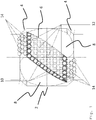
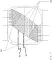
- the figure 1 shows a first embodiment of a stabilizer-reamer according to the invention.
- This stabilizer-reamer comprises a central cylindrical portion 2 and two conical portions 4 on either side of said central cylindrical portion.
- the central cylindrical portion 2 comprises helical blades 6 and spline profiles 8 placed between the helical blades.
- the central cylindrical portion 2 also comprises flat or slightly rounded diamond inserts.
- the leading and lateral edges of the helicoidal blades 6 comprise cutting diamond inserts 10, the central part of the blades comprising in turn at least one type of wear-resistant inserts 12.
- the two conical parts comprise a mixture of diamond inserts 14, the mixture comprising cutting diamond inserts and wear-resistant diamond inserts.
- the design of the tapered parts makes them suitable for front boring and rear boring operations.
- All diamond cutting inserts have a diamond particle size of between 18/20 and 40/50 mesh ASTM and a diamond concentration between 10% and 35% by volume, while wear-resistant diamond inserts have a grain size distribution.
- diamond between 40/50 and 120/140 mesh ASTM and a diamond concentration between 35% and 60% by volume.
- the diameter of the diamond inserts is generally between 6 and 25 mm and their height is generally between 3 and 30 mm.
- the typical compositions of the matrix of diamond inserts are as follows: 1 tungsten carbide: from 50 to 94% cobalt: from 50 to 6% 2 tungsten carbide: 40 to 96% cobalt: from 20 to 2% nickel: from 30 to 4% 3 tungsten carbide: from 50 to 94% 50 to 6% nickel 4 tungsten carbide: 40 to 60% titanium carbide: 10 to 50% cobalt or nickel: 50 to 10% 5 chromium carbide: from 50 to 94% nickel: from 50 to 6% 6 titanium carbide: 20 to 40% niobium carbide: 3 to 10% nickel: from 30 to 50% molybdenum: 10 to 20% aluminum: from 10 to 20%
- a stabilizer according to the invention comprises in fact at least one type of cutting inserts and a type of wear-resistant inserts, but it can also comprise more than two different types of inserts. It may include, for example, two types of wear-resistant inserts having the above-mentioned typical compositions.
- the proportion of carbide is advantageously reduced in order to have a more resilient matrix.
- the proportion of carbide is therefore generally lower in wear-resistant diamond inserts than in the impregnated cutting inserts.
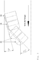
- the tapered portions of the stabilizer-reamer according to the invention comprise diamond inserts having a shape, a diameter and a length adapted to form a taper angle 17 which is between 5 ° and 25 °.
- This relatively soft angle compared to that disclosed in the state of the art, has been found to be particularly suited to the features of rear bore and front bore, increasing the contact area between the rear bore areas and bore before and the wall of the borehole.
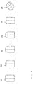
- the diamond inserts comprise rounded inserts 16, 18 and 20 of variable curvature.
- the figure 4 shows different embodiments of the shapes of diamond inserts according to the invention, these inserts 16, 18, 20 being used in combination, as detailed in the previous figures.
- the inserts 20 are fully rounded inserts, while the least curved round inserts 16 may have a radius of curvature of about 160 mm.
- Truncated inserts 22 are also disclosed in this figure, these inserts being rounded with a planar upper surface.
- Cylindrical inserts 24 having a flat top surface and longitudinally truncated cylindrical inserts 23, used in different embodiments of the invention are also shown on the figure 4 .
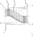
- the figure 5 shows another embodiment of a stabilizer-reamer according to the invention, this embodiment being particularly suitable when the formation of the well is ultra-hard and abrasive.
- This stabilizer-reamer includes longitudinally truncated inserts 23 in the side edges of the helical blades and cylindrical inserts 24 in the conical portions.
- the diamond inserts may be cutting inserts or wear resistant inserts, or a mixture of both.
- the figure 6 shows a sectional view of the lateral edge of the embodiment of the figure 5 .
- the figure 7 shows another embodiment of a stabilizer-reamer according to the invention.
- this stabilizer-reamer has cylindrical transition zones 26 between the helicoidal blades 6 and the conical portions 4, said cylindrical transition zones 26 comprising two rows of diamond cutting inserts.
- the cutting inserts provided in these regions increase the service life of the tool, the transition zones between the blades and the conical parts being regions of the tools highly exposed to destructive shocks with the wall of the borehole.
- the figure 8 and the figure 9 show other embodiments of the stabilizer-reamer according to the invention.
- the wear-resistant diamond inserts mentioned in the invention is replaced by a diamond laser coating 28.
- the diamond concentration of said diamond laser coating 28 is between 20 and 35% by volume, and the diamond particle size is between 40/50 mesh ASTM and 120/140 mesh ASTM.
- the diamond laser coating 28 covers the entire surface of the wear-resistant portion of the stabilizer.
- the diamond laser coating 28 is arranged in strips covering the entire width of the blade and alternating with a much thinner steel strip, this arrangement making it possible to prevent the propagation of cracks in the diamond laser coating 28. it can be seen in these figures, the two cylindrical edges of the stabilizer are still covered with cutting diamond inserts 12 soldered into pockets machined in the steel portion of the stabilizer.
Landscapes
- Engineering & Computer Science (AREA)
- Life Sciences & Earth Sciences (AREA)
- Mining & Mineral Resources (AREA)
- Geology (AREA)
- Mechanical Engineering (AREA)
- Physics & Mathematics (AREA)
- Environmental & Geological Engineering (AREA)
- Fluid Mechanics (AREA)
- General Life Sciences & Earth Sciences (AREA)
- Geochemistry & Mineralogy (AREA)
- Chemical & Material Sciences (AREA)
- Optics & Photonics (AREA)
- Plasma & Fusion (AREA)
- Materials Engineering (AREA)
- Metallurgy (AREA)
- Organic Chemistry (AREA)
- Earth Drilling (AREA)
- Milling, Broaching, Filing, Reaming, And Others (AREA)
Claims (15)
- Erweiterungsstabilisator für einen Bohrstrang, umfassend auf seiner externen Oberfläche eine Zusammenstellung von Einsätzen, wobei die Zusammenstellung Schneideinsätze und verschleißfeste Einsätze umfasst, dadurch gekennzeichnet, dass- die Schneideinsätze und verschleißfesten Einsätze Diamanteinsätze sind,- die verschleißfesten Diamanteinsätze (12) eine Korngröße des Diamanten, die kleiner, und eine Diamantkonzentration, die größer als die der Diamantschneideinsätze (10) sind, aufweisen.
- Erweiterungsstabilisator nach Anspruch 1, dadurch gekennzeichnet, dass die Diamantschneideinsätze (10) eine Korngröße des Diamanten, die zwischen 18/20 und 40/50 mesh ASTM liegt, und eine Diamantkonzentration, die zwischen 10 und 35 Volumenprozent liegt, aufweisen, und die verschleißfesten Diamanteinsätze (12) eine Korngröße des Diamanten, die zwischen 40/50 und 120/140 mesh ASTM liegt, und eine Diamantkonzentration, die zwischen 35 bis 60 Volumenprozent liegt, aufweisen.
- Erweiterungsstabilisator nach einem der vorhergehenden Ansprüche, dadurch gekennzeichnet, dass die Zusammensetzung der Diamanteinsätze mindestens ein Metall und ein Metallkarbid, das aus der Gruppe ausgewählt wird, die aus Wolframkarbid, Titankarbid, Tantalkarbid, Chromkarbid, Vanadiumkarbid, Niobkarbid und Molybdänkarbid besteht, umfasst.
- Erweiterungsstabilisator nach einem der vorhergehenden Ansprüche, dadurch gekennzeichnet, dass die Diamanteinsätze auf dem Erweiterungsstabilisator hartgelötet sind.
- Erweiterungsstabilisator nach einem der vorhergehenden Ansprüche, dadurch gekennzeichnet, dass er einen mittleren zylindrischen Teil (2) und zwei kegelförmige Teile (4) auf beiden Seiten des mittleren zylindrischen Teils (2) umfasst.
- Erweiterungsstabilisator nach Anspruch 5, dadurch gekennzeichnet, dass der mittlere zylindrische Teil (2) spiralförmige Blätter (6) umfasst.
- Erweiterungsstabilisator nach einem der Ansprüche 5 und 6, dadurch gekennzeichnet, dass der mittlere zylindrische Teil (2) eine Zusammenstellung (14) von Diamanteinsätzen umfasst, wobei die Zusammenstellung Diamantschneideinsätze (10) und verschleißfeste Diamanteinsätze (12) umfasst.
- Erweiterungsstabilisator nach einem der Ansprüche 6 oder 7, dadurch gekennzeichnet, dass die Leitkante und die Seitenkante der spiralförmigen Blätter (6) zwischen einer und fünf Reihen von Diamantschneideinsätzen (10) umfassen und der mittlere Teil der spiralförmigen Blätter (6) verschleißfeste Diamanteinsätze (12) umfasst.
- Erweiterungsstabilisator nach einem der Ansprüche 5 bis 8, dadurch gekennzeichnet, dass die beiden kegelförmigen Teile (4) eine Zusammenstellung (14) von Diamanteinsätzen umfassen, wobei die Zusammenstellung Diamantschneideinsätze (10) und verschleißfeste Diamanteinsätze (12) umfasst, wobei die Proportion der Schneideinsätze größer als 50 % der Gesamtanzahl der Einsätze in der Zusammenstellung (14) von Diamanteinsätzen ist.
- Erweiterungsstabilisator nach Anspruch 6 bis 9, dadurch gekennzeichnet, dass der Erweiterungsstabilisator zylindrische Übergangszonen (26) zwischen den spiralförmigen Blättern (6) und den kegelförmigen Teilen (4) umfasst, wobei die zylindrischen Übergangszonen (26) zwischen zwei Reihen und fünf Reihen von Diamantschneideinsätzen (10) umfassen.
- Erweiterungsstabilisator nach Anspruch 5 bis 10, dadurch gekennzeichnet, dass die beiden kegelförmigen Teile (4) Diamanteinsätze umfassen, die eine Form, einen Durchmesser und eine Länge aufweisen, die geeignet sind, um einen Kegelwinkel (17) zwischen 5° und 25° zu bilden.
- Erweiterungsstabilisator nach Anspruch 5 bis 11, dadurch gekennzeichnet, dass der mittlere zylindrische Teil (2) eine Diamantlaserbeschichtung (28) umfasst, wobei die Diamantkonzentration der Diamantlaserbeschichtung (28) zwischen 20 und 35 Volumenprozent liegt, und die Körnung des Diamanten zwischen 40/50 mesh ASTM und 120/140 mesh ASTM liegt.
- Verfahren zum Verbessern der Stabilisierungsfähigkeiten eines Erweiterungsstabilisators nach einem der vorhergehenden Ansprüche, dadurch gekennzeichnet, dass der Reibungskoeffizient zwischen dem Erweiterungsstabilisator und der Wand des Bohrlochs moduliert wird.
- Verfahren nach Anspruch 13, dadurch gekennzeichnet, dass das Modulieren des Reibungskoeffizienten zwischen dem Erweiterungsstabilisator und der Wand des Bohrlochs darin besteht, die Proportion der Diamantschneideinsätze (10) und der verschleißfesten Diamanteinsätze (12) in der Zusammenstellung (14) von Diamanteinsätzen auf dem mittleren Teil der spiralförmigen Blätter (6) des Erweiterungsstabilisators zu variieren.
- Verfahren nach Anspruch 14, dadurch gekennzeichnet, dass die Proportion der Diamantschneideinsätze (10) in der Zusammenstellung von Diamanteinsätzen auf dem mittleren Teil der spiralförmigen Blätter (6) des Erweiterungsstabilisators zwischen 0 % und 70 % der Gesamtanzahl von Diamanteinsätzen in der Zusammenstellung aus Diamanteinsätzen (14) variiert.
Applications Claiming Priority (2)
| Application Number | Priority Date | Filing Date | Title |
|---|---|---|---|
| BE2014/0411A BE1023426B1 (fr) | 2014-05-30 | 2014-05-30 | Stabilisateur-aleseur pour train de forage |
| PCT/EP2015/061069 WO2015181010A1 (fr) | 2014-05-30 | 2015-05-20 | Stabilisateur-aléseur pour train de forage |
Publications (2)
| Publication Number | Publication Date |
|---|---|
| EP3155201A1 EP3155201A1 (de) | 2017-04-19 |
| EP3155201B1 true EP3155201B1 (de) | 2018-09-26 |
Family
ID=51352368
Family Applications (1)
| Application Number | Title | Priority Date | Filing Date |
|---|---|---|---|
| EP15723944.3A Active EP3155201B1 (de) | 2014-05-30 | 2015-05-20 | Stabilisator-räumer für bohrgestänge |
Country Status (5)
| Country | Link |
|---|---|
| US (1) | US10323462B2 (de) |
| EP (1) | EP3155201B1 (de) |
| BE (1) | BE1023426B1 (de) |
| CA (1) | CA2949722C (de) |
| WO (1) | WO2015181010A1 (de) |
Families Citing this family (5)
| Publication number | Priority date | Publication date | Assignee | Title |
|---|---|---|---|---|
| CA3078957A1 (en) | 2017-10-10 | 2019-04-18 | Extreme Technologies, Llc | Wellbore reaming systems and devices |
| WO2019147820A1 (en) * | 2018-01-24 | 2019-08-01 | Stabil Drill Specialties, L.L.C. | Eccentric reaming tool |
| BE1028839B1 (fr) * | 2020-11-30 | 2022-06-28 | Diarotech Sa | Nouvelle technique de revêtement pour pièces d'usure |
| US11939818B2 (en) | 2021-12-01 | 2024-03-26 | T.J. Technology 2020 Inc. | Modular reamer |
| CN115182688B (zh) * | 2022-06-27 | 2025-09-05 | 中国地质大学(武汉) | 一种孕镶金刚石扶正器及其制造方法与应用 |
Citations (1)
| Publication number | Priority date | Publication date | Assignee | Title |
|---|---|---|---|---|
| US8607900B1 (en) * | 2012-08-27 | 2013-12-17 | LB Enterprises, LLC | Downhole tool engaging a tubing string between a drill bit and tubular for reaming a wellbore |
Family Cites Families (21)
| Publication number | Priority date | Publication date | Assignee | Title |
|---|---|---|---|---|
| US3250578A (en) * | 1964-01-27 | 1966-05-10 | Land And Marine Rental Company | Well apparatus |
| US3268274A (en) * | 1964-05-25 | 1966-08-23 | Exxon Production Research Co | Spiral blade stabilizer |
| US3343615A (en) * | 1966-08-15 | 1967-09-26 | Exxon Production Research Co | Drill collar with cutting surface |
| US3575247A (en) * | 1969-03-06 | 1971-04-20 | Shell Oil Co | Diamond bit unit |
| US4662461A (en) * | 1980-09-15 | 1987-05-05 | Garrett William R | Fixed-contact stabilizer |
| US4618010A (en) * | 1986-02-18 | 1986-10-21 | Team Engineering And Manufacturing, Inc. | Hole opener |
| GB8709229D0 (en) * | 1987-04-16 | 1987-05-20 | Shell Int Research | Tubular element |
| US5474143A (en) * | 1994-05-25 | 1995-12-12 | Smith International Canada, Ltd. | Drill bit reamer stabilizer |
| US6386302B1 (en) * | 1999-09-09 | 2002-05-14 | Smith International, Inc. | Polycrystaline diamond compact insert reaming tool |
| GB2377722B (en) * | 2000-05-30 | 2003-08-06 | Baker Hughes Inc | Laminated and composite impregnated cutting structures for drill bits |
| US7451836B2 (en) * | 2001-08-08 | 2008-11-18 | Smith International, Inc. | Advanced expandable reaming tool |
| AU2002951839A0 (en) * | 2002-09-30 | 2002-10-24 | Transco Manufacturing Australia Pty Ltd | Combined reamer and drill bit stabiliser |
| US8061451B2 (en) * | 2008-10-17 | 2011-11-22 | Strata Directional Technology, Llc | Vertical drilling system for controlling deviation |
| US7878273B2 (en) * | 2008-11-17 | 2011-02-01 | Omni Ip Ltd. | Ultra-hard drilling stabilizer |
| GB0904791D0 (en) | 2009-03-20 | 2009-05-06 | Turbopower Drilling Sal | Downhole drilling assembly |
| US8776912B2 (en) * | 2009-05-01 | 2014-07-15 | Smith International, Inc. | Secondary cutting structure |
| CN102656334B (zh) * | 2009-08-07 | 2015-11-25 | 史密斯国际有限公司 | 具有改进的过渡结构的高度耐磨的金刚石镶齿 |
| CN104712252B (zh) * | 2009-08-07 | 2018-09-14 | 史密斯国际有限公司 | 具有高的韧度和高的耐磨性的多晶金刚石材料 |
| US9051793B2 (en) * | 2011-12-13 | 2015-06-09 | Smith International, Inc. | Apparatuses and methods for stabilizing downhole tools |
| US20130153306A1 (en) * | 2011-12-19 | 2013-06-20 | Smith International, Inc. | Fixed cutter drill bit heel and back-ream cutter protections for abrasive applications |
| US9677344B2 (en) * | 2013-03-01 | 2017-06-13 | Baker Hughes Incorporated | Components of drilling assemblies, drilling assemblies, and methods of stabilizing drilling assemblies in wellbores in subterranean formations |
-
2014
- 2014-05-30 BE BE2014/0411A patent/BE1023426B1/fr active IP Right Grant
-
2015
- 2015-05-20 US US15/314,399 patent/US10323462B2/en active Active
- 2015-05-20 CA CA2949722A patent/CA2949722C/fr active Active
- 2015-05-20 EP EP15723944.3A patent/EP3155201B1/de active Active
- 2015-05-20 WO PCT/EP2015/061069 patent/WO2015181010A1/fr not_active Ceased
Patent Citations (1)
| Publication number | Priority date | Publication date | Assignee | Title |
|---|---|---|---|---|
| US8607900B1 (en) * | 2012-08-27 | 2013-12-17 | LB Enterprises, LLC | Downhole tool engaging a tubing string between a drill bit and tubular for reaming a wellbore |
Also Published As
| Publication number | Publication date |
|---|---|
| US10323462B2 (en) | 2019-06-18 |
| CA2949722C (fr) | 2021-10-26 |
| US20170198527A1 (en) | 2017-07-13 |
| WO2015181010A1 (fr) | 2015-12-03 |
| EP3155201A1 (de) | 2017-04-19 |
| CA2949722A1 (fr) | 2015-12-03 |
| BE1023426B1 (fr) | 2017-03-15 |
Similar Documents
| Publication | Publication Date | Title |
|---|---|---|
| BE1023426B1 (fr) | Stabilisateur-aleseur pour train de forage | |
| BE1012924A5 (fr) | Perfectionnements aux tetes de forage ou concernant celles-ci. | |
| BE1012823A5 (fr) | Elements rapportes a pointe superabrasive pour trepans de forage de terre. | |
| BE1012649A5 (fr) | Element de coupe superabrasif avec chanfrein plan supporte par un contrefort et trepans de forage equipes d'un tel element. | |
| BE1014915A5 (fr) | Structure de forage de formations souterraines. | |
| BE1015202A5 (fr) | Structure de forage, procede de forage avec celle-ci et procede de conception de la structure. | |
| BE1012751A5 (fr) | Trepan a lames rotatif dirigeable a agressivite longitudinale variable de la zone de front de taille. | |
| BE1016273A3 (fr) | Procede de forage de formations souterraines. | |
| BE1012752A5 (fr) | Trepans de forage rotatifs pour forage directionnel presentant des caracteristiques de coupe variables dependant du poids applique sur le trepan. | |
| BE1013652A3 (fr) | Trepans de forage a controle de la charge appliquee au dispositif de coupe et de la profondeur de coupe. | |
| BE1014519A5 (fr) | Tete de forage et son procede d'utilisation. | |
| BE1016350A3 (fr) | Appareil et procede de forage terrestre offrant une meilleure protection des alesoirs. | |
| BE1015740A3 (de) | ||
| BE1016271A3 (fr) | Trepan et son procede de fabrication. | |
| BE1016272A3 (fr) | Trepan et procede de forage. | |
| EP0944764B1 (de) | Bohrkopf | |
| BE1010801A3 (fr) | Outil de forage et/ou de carottage. | |
| BE1014353A5 (fr) | Element coupant et trepan tournant utilisant cet element. | |
| BE1001698A3 (fr) | Reglage de circulation de fluide pour trepans a lames. | |
| BE1013524A5 (fr) | Trepan a dents en acier comportant une couche de rechargement tres epaisse. | |
| BE1013451A5 (fr) | Structure de forage a region de front de taille non axiale. | |
| FR2915232A1 (fr) | Trepan pour le forage d'un puits et procede de forage associe. | |
| CA1108596A (fr) | Outil de forage a haut rendement a attaque rapide de la carotte | |
| BE1013521A3 (fr) | Element de coupe superabrasif comportant des interfaces arquees entre la table et le substrat. | |
| WO2013190219A1 (fr) | Element de garniture de forage avec zone d'activation des fluides |
Legal Events
| Date | Code | Title | Description |
|---|---|---|---|
| STAA | Information on the status of an ep patent application or granted ep patent |
Free format text: STATUS: THE INTERNATIONAL PUBLICATION HAS BEEN MADE |
|
| PUAI | Public reference made under article 153(3) epc to a published international application that has entered the european phase |
Free format text: ORIGINAL CODE: 0009012 |
|
| STAA | Information on the status of an ep patent application or granted ep patent |
Free format text: STATUS: REQUEST FOR EXAMINATION WAS MADE |
|
| 17P | Request for examination filed |
Effective date: 20161222 |
|
| AK | Designated contracting states |
Kind code of ref document: A1 Designated state(s): AL AT BE BG CH CY CZ DE DK EE ES FI FR GB GR HR HU IE IS IT LI LT LU LV MC MK MT NL NO PL PT RO RS SE SI SK SM TR |
|
| AX | Request for extension of the european patent |
Extension state: BA ME |
|
| DAV | Request for validation of the european patent (deleted) | ||
| DAX | Request for extension of the european patent (deleted) | ||
| REG | Reference to a national code |
Ref country code: DE Ref legal event code: R079 Ref document number: 602015016986 Country of ref document: DE Free format text: PREVIOUS MAIN CLASS: E21B0010260000 Ipc: E21B0010550000 |
|
| GRAP | Despatch of communication of intention to grant a patent |
Free format text: ORIGINAL CODE: EPIDOSNIGR1 |
|
| STAA | Information on the status of an ep patent application or granted ep patent |
Free format text: STATUS: GRANT OF PATENT IS INTENDED |
|
| RIC1 | Information provided on ipc code assigned before grant |
Ipc: C22C 29/02 20060101ALI20180319BHEP Ipc: B23K 103/00 20060101ALI20180319BHEP Ipc: B23K 101/00 20060101ALI20180319BHEP Ipc: E21B 10/56 20060101ALI20180319BHEP Ipc: B23K 1/00 20060101ALI20180319BHEP Ipc: E21B 10/54 20060101ALI20180319BHEP Ipc: E21B 17/10 20060101ALI20180319BHEP Ipc: E21B 10/55 20060101AFI20180319BHEP Ipc: E21B 10/26 20060101ALI20180319BHEP Ipc: B23K 26/34 20140101ALI20180319BHEP |
|
| INTG | Intention to grant announced |
Effective date: 20180417 |
|
| GRAS | Grant fee paid |
Free format text: ORIGINAL CODE: EPIDOSNIGR3 |
|
| GRAA | (expected) grant |
Free format text: ORIGINAL CODE: 0009210 |
|
| STAA | Information on the status of an ep patent application or granted ep patent |
Free format text: STATUS: THE PATENT HAS BEEN GRANTED |
|
| AK | Designated contracting states |
Kind code of ref document: B1 Designated state(s): AL AT BE BG CH CY CZ DE DK EE ES FI FR GB GR HR HU IE IS IT LI LT LU LV MC MK MT NL NO PL PT RO RS SE SI SK SM TR |
|
| REG | Reference to a national code |
Ref country code: GB Ref legal event code: FG4D Free format text: NOT ENGLISH |
|
| REG | Reference to a national code |
Ref country code: CH Ref legal event code: EP |
|
| REG | Reference to a national code |
Ref country code: AT Ref legal event code: REF Ref document number: 1046240 Country of ref document: AT Kind code of ref document: T Effective date: 20181015 |
|
| REG | Reference to a national code |
Ref country code: IE Ref legal event code: FG4D Free format text: LANGUAGE OF EP DOCUMENT: FRENCH |
|
| REG | Reference to a national code |
Ref country code: DE Ref legal event code: R096 Ref document number: 602015016986 Country of ref document: DE |
|
| REG | Reference to a national code |
Ref country code: RO Ref legal event code: EPE |
|
| REG | Reference to a national code |
Ref country code: NL Ref legal event code: FP |
|
| REG | Reference to a national code |
Ref country code: NO Ref legal event code: T2 Effective date: 20180926 |
|
| PG25 | Lapsed in a contracting state [announced via postgrant information from national office to epo] |
Ref country code: RS Free format text: LAPSE BECAUSE OF FAILURE TO SUBMIT A TRANSLATION OF THE DESCRIPTION OR TO PAY THE FEE WITHIN THE PRESCRIBED TIME-LIMIT Effective date: 20180926 Ref country code: SE Free format text: LAPSE BECAUSE OF FAILURE TO SUBMIT A TRANSLATION OF THE DESCRIPTION OR TO PAY THE FEE WITHIN THE PRESCRIBED TIME-LIMIT Effective date: 20180926 Ref country code: BG Free format text: LAPSE BECAUSE OF FAILURE TO SUBMIT A TRANSLATION OF THE DESCRIPTION OR TO PAY THE FEE WITHIN THE PRESCRIBED TIME-LIMIT Effective date: 20181226 Ref country code: GR Free format text: LAPSE BECAUSE OF FAILURE TO SUBMIT A TRANSLATION OF THE DESCRIPTION OR TO PAY THE FEE WITHIN THE PRESCRIBED TIME-LIMIT Effective date: 20181227 Ref country code: LT Free format text: LAPSE BECAUSE OF FAILURE TO SUBMIT A TRANSLATION OF THE DESCRIPTION OR TO PAY THE FEE WITHIN THE PRESCRIBED TIME-LIMIT Effective date: 20180926 Ref country code: FI Free format text: LAPSE BECAUSE OF FAILURE TO SUBMIT A TRANSLATION OF THE DESCRIPTION OR TO PAY THE FEE WITHIN THE PRESCRIBED TIME-LIMIT Effective date: 20180926 |
|
| REG | Reference to a national code |
Ref country code: DE Ref legal event code: R082 Ref document number: 602015016986 Country of ref document: DE Representative=s name: NOVAGRAAF BREVETS, FR Ref country code: DE Ref legal event code: R081 Ref document number: 602015016986 Country of ref document: DE Owner name: FASTIP S.A., BE Free format text: FORMER OWNERS: AURORA BIT CONSULTANCY LTD, ABERDEEN, GB; DIAROTECH S.A., GILLY, BE Ref country code: DE Ref legal event code: R081 Ref document number: 602015016986 Country of ref document: DE Owner name: AURORA BIT CONSULTANCY LTD, GB Free format text: FORMER OWNERS: AURORA BIT CONSULTANCY LTD, ABERDEEN, GB; DIAROTECH S.A., GILLY, BE |
|
| REG | Reference to a national code |
Ref country code: LT Ref legal event code: MG4D |
|
| PG25 | Lapsed in a contracting state [announced via postgrant information from national office to epo] |
Ref country code: HR Free format text: LAPSE BECAUSE OF FAILURE TO SUBMIT A TRANSLATION OF THE DESCRIPTION OR TO PAY THE FEE WITHIN THE PRESCRIBED TIME-LIMIT Effective date: 20180926 Ref country code: LV Free format text: LAPSE BECAUSE OF FAILURE TO SUBMIT A TRANSLATION OF THE DESCRIPTION OR TO PAY THE FEE WITHIN THE PRESCRIBED TIME-LIMIT Effective date: 20180926 Ref country code: AL Free format text: LAPSE BECAUSE OF FAILURE TO SUBMIT A TRANSLATION OF THE DESCRIPTION OR TO PAY THE FEE WITHIN THE PRESCRIBED TIME-LIMIT Effective date: 20180926 |
|
| REG | Reference to a national code |
Ref country code: GB Ref legal event code: 732E Free format text: REGISTERED BETWEEN 20190207 AND 20190213 |
|
| RAP2 | Party data changed (patent owner data changed or rights of a patent transferred) |
Owner name: FASTIP SA Owner name: AURORA BIT CONSULTANCY LTD |
|
| REG | Reference to a national code |
Ref country code: AT Ref legal event code: MK05 Ref document number: 1046240 Country of ref document: AT Kind code of ref document: T Effective date: 20180926 |
|
| REG | Reference to a national code |
Ref country code: BE Ref legal event code: PD Owner name: AURORA BIT CONSULTANCY LTD; GB Free format text: DETAILS ASSIGNMENT: CHANGE OF OWNER(S), CESSION; FORMER OWNER NAME: AURORA BIT CONSULTANCY LTD Effective date: 20190125 |
|
| REG | Reference to a national code |
Ref country code: DE Ref legal event code: R082 Ref document number: 602015016986 Country of ref document: DE Representative=s name: NOVAGRAAF BREVETS, FR Ref country code: DE Ref legal event code: R081 Ref document number: 602015016986 Country of ref document: DE Owner name: FASTIP S.A., BE Free format text: FORMER OWNERS: AURORA BIT CONSULTANCY LTD, ABERDEEN, GB; FASTIP S.A., FLEURUS, BE |
|
| REG | Reference to a national code |
Ref country code: NL Ref legal event code: PD Owner name: AURORA BIT CONSULTANCY LTD; GB Free format text: DETAILS ASSIGNMENT: CHANGE OF OWNER(S), ASSIGNMENT; FORMER OWNER NAME: DIAROTECH S.A. Effective date: 20190131 |
|
| PG25 | Lapsed in a contracting state [announced via postgrant information from national office to epo] |
Ref country code: EE Free format text: LAPSE BECAUSE OF FAILURE TO SUBMIT A TRANSLATION OF THE DESCRIPTION OR TO PAY THE FEE WITHIN THE PRESCRIBED TIME-LIMIT Effective date: 20180926 Ref country code: CZ Free format text: LAPSE BECAUSE OF FAILURE TO SUBMIT A TRANSLATION OF THE DESCRIPTION OR TO PAY THE FEE WITHIN THE PRESCRIBED TIME-LIMIT Effective date: 20180926 Ref country code: IS Free format text: LAPSE BECAUSE OF FAILURE TO SUBMIT A TRANSLATION OF THE DESCRIPTION OR TO PAY THE FEE WITHIN THE PRESCRIBED TIME-LIMIT Effective date: 20190126 Ref country code: AT Free format text: LAPSE BECAUSE OF FAILURE TO SUBMIT A TRANSLATION OF THE DESCRIPTION OR TO PAY THE FEE WITHIN THE PRESCRIBED TIME-LIMIT Effective date: 20180926 Ref country code: ES Free format text: LAPSE BECAUSE OF FAILURE TO SUBMIT A TRANSLATION OF THE DESCRIPTION OR TO PAY THE FEE WITHIN THE PRESCRIBED TIME-LIMIT Effective date: 20180926 Ref country code: PL Free format text: LAPSE BECAUSE OF FAILURE TO SUBMIT A TRANSLATION OF THE DESCRIPTION OR TO PAY THE FEE WITHIN THE PRESCRIBED TIME-LIMIT Effective date: 20180926 |
|
| REG | Reference to a national code |
Ref country code: GB Ref legal event code: 732E Free format text: REGISTERED BETWEEN 20190411 AND 20190417 |
|
| REG | Reference to a national code |
Ref country code: NL Ref legal event code: PD Owner name: FASTIP SA; BE Free format text: DETAILS ASSIGNMENT: CHANGE OF OWNER(S), ASSIGNMENT; FORMER OWNER NAME: FASTIP SA Effective date: 20190325 |
|
| PG25 | Lapsed in a contracting state [announced via postgrant information from national office to epo] |
Ref country code: SK Free format text: LAPSE BECAUSE OF FAILURE TO SUBMIT A TRANSLATION OF THE DESCRIPTION OR TO PAY THE FEE WITHIN THE PRESCRIBED TIME-LIMIT Effective date: 20180926 Ref country code: PT Free format text: LAPSE BECAUSE OF FAILURE TO SUBMIT A TRANSLATION OF THE DESCRIPTION OR TO PAY THE FEE WITHIN THE PRESCRIBED TIME-LIMIT Effective date: 20190126 Ref country code: SM Free format text: LAPSE BECAUSE OF FAILURE TO SUBMIT A TRANSLATION OF THE DESCRIPTION OR TO PAY THE FEE WITHIN THE PRESCRIBED TIME-LIMIT Effective date: 20180926 |
|
| REG | Reference to a national code |
Ref country code: BE Ref legal event code: PD Owner name: FASTIP SA; BE Free format text: DETAILS ASSIGNMENT: CHANGE OF OWNER(S), CESSION; FORMER OWNER NAME: AURORA BIT CONSULTANCY LTD Effective date: 20190319 |
|
| REG | Reference to a national code |
Ref country code: NO Ref legal event code: CHAD Owner name: FASTIP SA, BE |
|
| REG | Reference to a national code |
Ref country code: DE Ref legal event code: R097 Ref document number: 602015016986 Country of ref document: DE |
|
| PG25 | Lapsed in a contracting state [announced via postgrant information from national office to epo] |
Ref country code: DK Free format text: LAPSE BECAUSE OF FAILURE TO SUBMIT A TRANSLATION OF THE DESCRIPTION OR TO PAY THE FEE WITHIN THE PRESCRIBED TIME-LIMIT Effective date: 20180926 |
|
| PLBE | No opposition filed within time limit |
Free format text: ORIGINAL CODE: 0009261 |
|
| STAA | Information on the status of an ep patent application or granted ep patent |
Free format text: STATUS: NO OPPOSITION FILED WITHIN TIME LIMIT |
|
| 26N | No opposition filed |
Effective date: 20190627 |
|
| PG25 | Lapsed in a contracting state [announced via postgrant information from national office to epo] |
Ref country code: SI Free format text: LAPSE BECAUSE OF FAILURE TO SUBMIT A TRANSLATION OF THE DESCRIPTION OR TO PAY THE FEE WITHIN THE PRESCRIBED TIME-LIMIT Effective date: 20180926 |
|
| REG | Reference to a national code |
Ref country code: CH Ref legal event code: PL |
|
| PG25 | Lapsed in a contracting state [announced via postgrant information from national office to epo] |
Ref country code: CH Free format text: LAPSE BECAUSE OF NON-PAYMENT OF DUE FEES Effective date: 20190531 Ref country code: LI Free format text: LAPSE BECAUSE OF NON-PAYMENT OF DUE FEES Effective date: 20190531 Ref country code: MC Free format text: LAPSE BECAUSE OF FAILURE TO SUBMIT A TRANSLATION OF THE DESCRIPTION OR TO PAY THE FEE WITHIN THE PRESCRIBED TIME-LIMIT Effective date: 20180926 |
|
| PG25 | Lapsed in a contracting state [announced via postgrant information from national office to epo] |
Ref country code: LU Free format text: LAPSE BECAUSE OF NON-PAYMENT OF DUE FEES Effective date: 20190520 |
|
| PG25 | Lapsed in a contracting state [announced via postgrant information from national office to epo] |
Ref country code: TR Free format text: LAPSE BECAUSE OF FAILURE TO SUBMIT A TRANSLATION OF THE DESCRIPTION OR TO PAY THE FEE WITHIN THE PRESCRIBED TIME-LIMIT Effective date: 20180926 |
|
| PG25 | Lapsed in a contracting state [announced via postgrant information from national office to epo] |
Ref country code: IE Free format text: LAPSE BECAUSE OF NON-PAYMENT OF DUE FEES Effective date: 20190520 |
|
| PG25 | Lapsed in a contracting state [announced via postgrant information from national office to epo] |
Ref country code: CY Free format text: LAPSE BECAUSE OF FAILURE TO SUBMIT A TRANSLATION OF THE DESCRIPTION OR TO PAY THE FEE WITHIN THE PRESCRIBED TIME-LIMIT Effective date: 20180926 |
|
| PG25 | Lapsed in a contracting state [announced via postgrant information from national office to epo] |
Ref country code: HU Free format text: LAPSE BECAUSE OF FAILURE TO SUBMIT A TRANSLATION OF THE DESCRIPTION OR TO PAY THE FEE WITHIN THE PRESCRIBED TIME-LIMIT; INVALID AB INITIO Effective date: 20150520 Ref country code: MT Free format text: LAPSE BECAUSE OF FAILURE TO SUBMIT A TRANSLATION OF THE DESCRIPTION OR TO PAY THE FEE WITHIN THE PRESCRIBED TIME-LIMIT Effective date: 20180926 |
|
| PG25 | Lapsed in a contracting state [announced via postgrant information from national office to epo] |
Ref country code: MK Free format text: LAPSE BECAUSE OF FAILURE TO SUBMIT A TRANSLATION OF THE DESCRIPTION OR TO PAY THE FEE WITHIN THE PRESCRIBED TIME-LIMIT Effective date: 20180926 |
|
| PGFP | Annual fee paid to national office [announced via postgrant information from national office to epo] |
Ref country code: NL Payment date: 20260527 Year of fee payment: 12 |
|
| PGFP | Annual fee paid to national office [announced via postgrant information from national office to epo] |
Ref country code: GB Payment date: 20260520 Year of fee payment: 12 |
|
| PGFP | Annual fee paid to national office [announced via postgrant information from national office to epo] |
Ref country code: IT Payment date: 20260512 Year of fee payment: 12 |
|
| PGFP | Annual fee paid to national office [announced via postgrant information from national office to epo] |
Ref country code: DE Payment date: 20260521 Year of fee payment: 12 |
|
| PGFP | Annual fee paid to national office [announced via postgrant information from national office to epo] |
Ref country code: NO Payment date: 20260521 Year of fee payment: 12 |
|
| PGFP | Annual fee paid to national office [announced via postgrant information from national office to epo] |
Ref country code: RO Payment date: 20260508 Year of fee payment: 12 Ref country code: BE Payment date: 20260526 Year of fee payment: 12 |
|
| PGFP | Annual fee paid to national office [announced via postgrant information from national office to epo] |
Ref country code: FR Payment date: 20260526 Year of fee payment: 12 |