EP3155228B1 - Verfahren zum betreiben einer maschinenanlage mit einem wellenstrang - Google Patents
Verfahren zum betreiben einer maschinenanlage mit einem wellenstrang Download PDFInfo
- Publication number
- EP3155228B1 EP3155228B1 EP15762950.2A EP15762950A EP3155228B1 EP 3155228 B1 EP3155228 B1 EP 3155228B1 EP 15762950 A EP15762950 A EP 15762950A EP 3155228 B1 EP3155228 B1 EP 3155228B1
- Authority
- EP
- European Patent Office
- Prior art keywords
- stress
- shaft train
- maximum
- determined
- stress amplitude
- Prior art date
- Legal status (The legal status is an assumption and is not a legal conclusion. Google has not performed a legal analysis and makes no representation as to the accuracy of the status listed.)
- Active
Links
Images

Classifications
-
- F—MECHANICAL ENGINEERING; LIGHTING; HEATING; WEAPONS; BLASTING
- F01—MACHINES OR ENGINES IN GENERAL; ENGINE PLANTS IN GENERAL; STEAM ENGINES
- F01D—NON-POSITIVE DISPLACEMENT MACHINES OR ENGINES, e.g. STEAM TURBINES
- F01D21/00—Shutting-down of machines or engines, e.g. in emergency; Regulating, controlling, or safety means not otherwise provided for
-
- G—PHYSICS
- G01—MEASURING; TESTING
- G01H—MEASUREMENT OF MECHANICAL VIBRATIONS OR ULTRASONIC, SONIC OR INFRASONIC WAVES
- G01H1/00—Measuring characteristics of vibrations in solids by using direct conduction to the detector
- G01H1/12—Measuring characteristics of vibrations in solids by using direct conduction to the detector of longitudinal or not specified vibrations
- G01H1/14—Frequency
-
- F—MECHANICAL ENGINEERING; LIGHTING; HEATING; WEAPONS; BLASTING
- F01—MACHINES OR ENGINES IN GENERAL; ENGINE PLANTS IN GENERAL; STEAM ENGINES
- F01D—NON-POSITIVE DISPLACEMENT MACHINES OR ENGINES, e.g. STEAM TURBINES
- F01D17/00—Regulating or controlling by varying flow
- F01D17/02—Arrangement of sensing elements
- F01D17/04—Arrangement of sensing elements responsive to load
-
- F—MECHANICAL ENGINEERING; LIGHTING; HEATING; WEAPONS; BLASTING
- F01—MACHINES OR ENGINES IN GENERAL; ENGINE PLANTS IN GENERAL; STEAM ENGINES
- F01D—NON-POSITIVE DISPLACEMENT MACHINES OR ENGINES, e.g. STEAM TURBINES
- F01D21/00—Shutting-down of machines or engines, e.g. in emergency; Regulating, controlling, or safety means not otherwise provided for
- F01D21/003—Arrangements for testing or measuring
-
- F—MECHANICAL ENGINEERING; LIGHTING; HEATING; WEAPONS; BLASTING
- F01—MACHINES OR ENGINES IN GENERAL; ENGINE PLANTS IN GENERAL; STEAM ENGINES
- F01D—NON-POSITIVE DISPLACEMENT MACHINES OR ENGINES, e.g. STEAM TURBINES
- F01D5/00—Blades; Blade-carrying members; Heating, heat-insulating, cooling or antivibration means on the blades or the members
- F01D5/02—Blade-carrying members, e.g. rotors
- F01D5/027—Arrangements for balancing
-
- F—MECHANICAL ENGINEERING; LIGHTING; HEATING; WEAPONS; BLASTING
- F01—MACHINES OR ENGINES IN GENERAL; ENGINE PLANTS IN GENERAL; STEAM ENGINES
- F01D—NON-POSITIVE DISPLACEMENT MACHINES OR ENGINES, e.g. STEAM TURBINES
- F01D5/00—Blades; Blade-carrying members; Heating, heat-insulating, cooling or antivibration means on the blades or the members
- F01D5/02—Blade-carrying members, e.g. rotors
- F01D5/04—Blade-carrying members, e.g. rotors for radial-flow machines or engines
-
- F—MECHANICAL ENGINEERING; LIGHTING; HEATING; WEAPONS; BLASTING
- F01—MACHINES OR ENGINES IN GENERAL; ENGINE PLANTS IN GENERAL; STEAM ENGINES
- F01D—NON-POSITIVE DISPLACEMENT MACHINES OR ENGINES, e.g. STEAM TURBINES
- F01D5/00—Blades; Blade-carrying members; Heating, heat-insulating, cooling or antivibration means on the blades or the members
- F01D5/02—Blade-carrying members, e.g. rotors
- F01D5/06—Rotors for more than one axial stage, e.g. of drum or multiple disc type; Details thereof, e.g. shafts, shaft connections
-
- F—MECHANICAL ENGINEERING; LIGHTING; HEATING; WEAPONS; BLASTING
- F01—MACHINES OR ENGINES IN GENERAL; ENGINE PLANTS IN GENERAL; STEAM ENGINES
- F01D—NON-POSITIVE DISPLACEMENT MACHINES OR ENGINES, e.g. STEAM TURBINES
- F01D5/00—Blades; Blade-carrying members; Heating, heat-insulating, cooling or antivibration means on the blades or the members
- F01D5/12—Blades
- F01D5/26—Antivibration means not restricted to blade form or construction or to blade-to-blade connections or to the use of particular materials
-
- G—PHYSICS
- G01—MEASURING; TESTING
- G01H—MEASUREMENT OF MECHANICAL VIBRATIONS OR ULTRASONIC, SONIC OR INFRASONIC WAVES
- G01H1/00—Measuring characteristics of vibrations in solids by using direct conduction to the detector
- G01H1/10—Measuring characteristics of vibrations in solids by using direct conduction to the detector of torsional vibrations
-
- G—PHYSICS
- G01—MEASURING; TESTING
- G01H—MEASUREMENT OF MECHANICAL VIBRATIONS OR ULTRASONIC, SONIC OR INFRASONIC WAVES
- G01H1/00—Measuring characteristics of vibrations in solids by using direct conduction to the detector
- G01H1/12—Measuring characteristics of vibrations in solids by using direct conduction to the detector of longitudinal or not specified vibrations
- G01H1/16—Amplitude
Definitions
- the invention relates to a method for operating a machine system with a shaft train.
- An engine plant such as a power plant for generating electricity, has an electric generator and at least one turbine, the turbine driving the generator.
- the turbine and the generator are arranged on a common shaft train. It is possible to provide couplings in the shaft train to couple individual turbines into the shaft train or decouple them from the shaft train.
- the generator feeds electricity into a power grid during operation of the power plant. Electrical accidents in the power grid can cause a torsional vibration of the shaft train is excited via the generator. In the worst case, it may come to an excitation of one of the natural frequencies of the shaft train. The excitation at a natural frequency leads to a high torsional stress load of the shaft train, which can lead to a reduction of its service life or to the formation of stress cracks. It is expected that the incidents in the electricity grid will occur more frequently in the future because the structures of the electricity grid change as part of the energy turnaround.
- the load of the shaft train is measured by measuring its rotational speed in high resolution at several axial positions of the shaft train. From the differences of the speeds at the different axial positions is then deduced on the load of the shaft train.
- the measurement technique and the associated evaluation are expensive.
- DE 40 32 299 A1 describes a method for monitoring a rotatable component, in which the vibration displacement of the component in the radial direction to the component and the rotational position of the component are measured time-dependent.
- EP 0 585 623 A2 describes a method for the early detection of a crack in a rotating shaft.
- DE 27 34 396 A1 describes a method for monitoring torsional vibrations on waves, in which the instantaneous power of the generator is measured.
- the object of the invention is to provide a method for operating a machine system with a shaft train, in which loads of the shaft train are easily detectable by torsional vibrations.
- the inventive method for operating a turbine system having a shaft train comprises the steps of: a) calculating the natural frequency of at least one torsional vibration mode of the shaft train and computationally determining the mechanical stresses of the shaft train occurring during a period of oscillation of the torsional vibration mode; b) determining a respective correlation for each torsional vibration mode between a first stress amplitude occurring at a position of the wave strand susceptible to the formation of torsional stress damage and a second stress amplitude occurring at a measurement point of the stress wave, for each of them Torsional vibration mode calculated voltages; c) setting a maximum first voltage amplitude for the position; d) determining a maximum second voltage amplitude corresponding to the maximum first voltage amplitude for the measuring point based on the correlation; e) Measuring the voltage of the shaft train while the shaft train rotates at the measuring point in dependence from the time; f) determining a voltage amplitude at each natural frequency from the measured voltage; g) outputting a signal in the event that
- the method is advantageously easy to carry out.
- the voltage amplitudes at the position can advantageously be determined with high accuracy.
- Measures can be taken on the signal to reduce the torsional vibrations of the shaft train.
- the machine installation is a power plant for supplying electricity to a power grid
- a desynchronization between the excitations from the power grid and the torsional oscillations of the shaft train can be carried out. This can be done, for example, by changing its natural frequencies by decoupling a turbine or a plurality of turbines from the shaft train. It is also possible to decouple the power plant from the mains by interrupting electrical lines.
- the voltage is measured by means of a magnetostrictive sensor and / or by means of a strain gauge, wherein the voltages measured by means of the strain gauge are transmitted by means of telemetry.
- the magnetostrictive sensor generates a high-frequency magnetic field by means of a transmitting coil and flows through the surface of the shaft strand with the magnetic field.
- the magnetostrictive sensor has one or more receiving coils, which form a magnetic circuit with the transmitting coil and are specially arranged for the detection of torsional stresses. With the special arrangement of the transmitting coil and receiving coils, the magnetic susceptibility can be determined on the surface of the shaft strand.
- the signal detected by the receiver coils also depends on the mechanical stress of the surface of the wave train.
- the magnetostrictive sensor outputs an analog output signal that is proportional to the torsional strain of the shaft train. Due to the proportionality of the output signal to the torsion voltage, the data processing is advantageous only a little compute-intensive, whereby the method is simple and fast to carry out. Both the magnetostrictive sensor and the strain gages determine the tension of the shaft train directly, whereby the method is also easy to carry out.
- step f) the voltages measured in step e) are filtered by means of a bandpass filter which allows a frequency band arranged around the natural frequency to pass and / or a Fourier transformation, in particular a fast Fourier transformation Step e) measured voltages is performed.
- a bandpass filter which allows a frequency band arranged around the natural frequency to pass and / or a Fourier transformation, in particular a fast Fourier transformation Step e) measured voltages is performed.
- the voltage amplitudes of the different torsional vibration modes can advantageously be easily determined.
- the signal can be output a short time after reaching the maximum second voltage amplitude.
- the Fourier transformation or the Fast Fourier transformation is applied, the signal is output after the completion of the calculation.
- step e) the voltage is measured at a plurality of measuring points arranged in different axial positions of the shaft train.
- a high accuracy of the natural frequencies can be achieved by an arithmetic means of the determined in the plurality of measuring points natural frequencies.
- one of the measuring points coincides with a vibration node of one of the torsional vibration modes, as a result of which the torsional vibration mode would not be visible with the measuring point.
- the probability is very low that all vibration nodes lie on the measuring points for a torsional vibration mode. This can be detected with a high probability all relevant torsional vibration modes.
- step f) preferably only one measuring point is used for a selected torsional vibration mode, which has the highest mechanical stress for the selected torsional vibration mode in step a). This advantageously achieves a high signal-to-noise ratio in the determination of the voltage amplitudes.
- the voltage amplitudes are assigned to one of the natural frequencies in which an experimental ratio of the voltage amplitudes and / or oscillation phases determined in step f) is formed at the plurality of measuring points, a mathematical ratio of the computationally determined Voltage amplitudes and / or vibration phases is formed at the plurality of measuring points and the experimental ratio is compared with the calculated ratio.
- the torsional vibration modes in which the shaft strand oscillates can advantageously be correctly determined with a high probability.
- the eigenfrequencies computationally determined in step a) are either lower than or equal to two and one-half times the rotational frequency of the shaft train or, in the case where the machinery is a power plant for power generation and the grid frequency is higher than the rotational frequency, lower or equal two and a half times the Mains frequency are.
- These natural frequencies result in particularly strong stress loads of the shaft train, so that monitoring of these frequencies is particularly advantageous.
- the computational determination of the natural frequency and of the mechanical stresses preferably takes into account the centrifugal force load which the shaft train has during operation of the machine installation.
- the correlation determined in step b) between the first voltage amplitude and the second voltage amplitude is preferably a proportionality.
- step c) an additional third maximum voltage amplitude which is higher than the first maximum voltage amplitude is preferably determined for the position, in step d) a maximum fourth voltage amplitude corresponding to the maximum third voltage amplitude for the measuring point is determined on the basis of the correlation and in step g) outputs a stop signal in the event that the determined in step f) voltage amplitude at the natural frequency reaches the maximum fourth voltage amplitude, the stop signal triggers a shutdown of the machinery. This can advantageously be prevented automatically too high a voltage load of the shaft train.
- the method comprises the step: d1) roughly calibrating the magnetostrictive sensor and / or the strain gauge on a shaft which is loaded by means of a testing machine with a defined voltage.
- the machinery has a generator and that the process is performed with the step of: d2) fine calibrating the magnetostrictive sensor and / or the strain gauge as the shaft train rotates using a voltage determined at the measurement point, using the output from the generator Performance is determined. From the output from the generator power can be deduced on the torque that exerts the generator on the shaft train. From the torque can then on the in the Wavelength occurring voltages are closed. This can be done advantageously the calibration of the real shaft train and the operation of the machinery.
- step b) correlations be determined for a plurality of positions of the wave-train that are susceptible to the formation of stress damage, in step c) for each position a respective maximum first stress amplitude is determined, in step d) for each the positions a corresponding maximum second voltage amplitude is determined and in step g) the signal is output in the event that one of the maximum second voltage amplitudes is reached.
- a plurality of critical points of the shaft train can advantageously be monitored with only a single measuring point.
- the maximum first voltage amplitudes at the different positions may be the same or different from each other. It is also possible to set third maximum voltage amplitudes for the plurality of positions, whereby these too may be the same or different from one another.
- the measuring points are arranged on the shaft train in the region of an exposed section of the shaft train, in the region of a section of the shaft train accessible to the measuring technology and / or in a region of a mathematically determined maximum stress.
- the positions are preferably arranged in the region of bearings, couplings and / or blade roots. These are advantageously positions which are particularly prone to stress damage.
- the natural frequencies and the voltages are preferably determined by calculation using a finite element method.
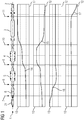
- a machine 1 has a generator 3 and at least one turbine, wherein the generator 3 and the turbine are arranged on a common shaft strand 2.
- the machinery 1 may also include a plurality of wave strands, the process being performed with each of the wave strands.
- the machinery according to FIG. 1 has a first turbine 4, a second turbine 5, a third turbine 6 and a fourth turbine 21, which are arranged on an axial side of the generator 3 in this order with increasing distance from the generator 3.
- the shaft train 2 has a first measuring point 7, a second measuring point 8, a third measuring point 9, a fourth measuring point 10 and a fifth measuring point 11, which are arranged at different axial positions of the shaft train 2 accessible to a measuring technique.
- FIG. 1 are also computationally determined Torsionsschwingungsmoden shown. Shown here are the four lowest-frequency torsional vibration modes 14 to 17, wherein the first torsional vibration mode 14 has the lowest natural frequency, the second torsional vibration mode 15, the second lowest natural frequency, the third torsional vibration mode 16, the third lowest natural frequency and the fourth torsional vibration mode 17, the fourth lowest natural frequency.
- the four natural frequencies are less than two and a half times the rotational frequency of the shaft train or two and a half times the network frequency, whichever is higher of the two frequencies.
- Each of the torsional vibration modes 14 to 17 is described by a respective plot in which the abscissa 12 is the axial position of the shaft train 2 and the ordinate 13, the angle of rotation of the shaft strand 3 is plotted. Because the gradient of the angle of rotation is proportional to the mechanical stress, by forming the gradient of the angle of rotation, the mechanical stress can be determined by calculation. It is also possible to determine the mechanical stress by means of a finite element method.
- At least one position of the shaft train 2 that is susceptible to the formation of stress damage is identified.
- the stress damage can be stress cracks and / or violent fractures. These positions may be in the range of bearings, couplings and / or blade roots, for example.
- a maximum first voltage amplitude is set, which is chosen such that it is not achieved in a normal operation of the machinery in which no resonant disturbances occur. Furthermore, it is chosen such that, when reached, no voltage damage occurs at the position.
- the maximum first voltage amplitude is the same for all torsional vibration modes 14 to 17. It is also possible to set a maximum third voltage amplitude for the position which is higher than the maximum first voltage amplitude. The third maximum voltage amplitude is selected such that, when reached, no voltage damage to the shaft train occurs.
- a correlation between the voltage amplitude at the position and the voltage amplitude at at least one of the measuring points 7 to 11 is determined for each torsional vibration mode, the correlation being a proportionality.
- a second maximum voltage amplitude for the measuring point 7 to 11 can be determined, the second maximum voltage amplitude occurring at the measuring point 7 to 11 when the first maximum voltage amplitude occurs at the position.
- a fourth maximum voltage amplitude for the measuring point 7 to 11 can also be determined. wherein the fourth maximum voltage amplitude occurs at the measuring point 7 to 11 when the third maximum voltage amplitude occurs at the position.
- the mechanical stress of the radially outer surface of the shaft train 2 is measured at each measuring point 7 to 11, each with at least one magnetostrictive sensor 18.
- a plurality of magnetostrictive sensors can be provided at each measuring point 7 to 11.
- the magnetostrictive sensor 18 has a transmitting coil, by means of which a magnetic field is generated.
- the surface of the shaft strand 2 is flooded with the magnetic field.
- the magnetostrictive sensor 18 has a receiver coil or a plurality of receiver coils, which are arranged in a magnetic circuit together with the transmitting coil and the flooded surface of the shaft strand 2 so suitable that thus the magnetic susceptibility of the surface of the shaft strand 2 can be determined.
- the magnetic susceptibility of the shaft strand 2 depends on its mechanical stress.
- the signal output by the magnetostrictive sensor is proportional to the torsion voltage of the magnetic field.
- the excitation coil and the receiver coils are integrated in a measuring head 19 of the magnetostrictive sensor 18. Between the measuring head 19 and the shaft train 2, an air gap 20 is arranged, whereby the method with the magnetostrictive sensor 18 can be performed without contact.
- the mechanical stresses are measured time-resolved by means of the magnetostrictive sensor 18.
- the measured voltages can then be filtered by means of a bandpass filter, which passes a frequency band arranged around the natural frequency of the torsional vibration mode.
- a bandpass filter which passes a frequency band arranged around the natural frequency of the torsional vibration mode.
- the signal is output when the filtered voltage reaches or exceeds the lowest of the second maximum voltage amplitudes of the plurality of torsional vibration modes.
- a shutdown of the engine system 1 can be provided in the event that the filtered voltage reaches or exceeds the maximum fourth voltage amplitude.
- a specific torsional vibration mode 14 to 17 can use only a single measuring point 7 to 11. In this case, that measuring point 7 to 11 can be used, which has the highest calculated voltage for the specific torsional vibration mode 14 to 17 in order to achieve a high signal to noise ratio.
- each torsional vibration mode 14 to 17 can identify that measuring point 7 to 11, which has the largest gradient of the rotation angle.
- each torsional vibration mode 14 to 17 it is possible for each torsional vibration mode 14 to 17 to identify the measuring point 7 to 11 having the highest calculated voltages. In FIG. 1 For example, this is the third measuring point 9 for the first torsional vibration mode 14, the third measuring point 9 for the second torsional vibration mode 15, the second measuring point 8 for the third torsional vibration mode 16 and the fifth measuring point 11 for the fourth torsional vibration mode 17.
- FIG. 3 illustrates the method in a flowchart.
- a rotor dynamic calculation is performed, in which the natural frequency for at least one torsional vibration mode of the shaft train 2 and the mechanical stresses of the shaft train 2 occurring during a vibration period of the torsional vibration mode are determined by calculation.
- step c the voltages of the shaft train 2 are measured, and in step d , the measured voltages are displayed.
- the measured voltages are filtered by means of the band-pass filters to determine the voltage amplitudes at the respective natural frequency.
- step f the filtered voltage amplitudes are displayed.
- step g it is queried whether the filtered voltage amplitude exceeds the limit value ⁇ STORE . If this is the case, the measured voltages are stored in step h . Alternatively, it is possible to permanently store the measured voltages with large time steps and to store the measured voltages with small time steps in step h .
- step i it is queried whether the filtered voltage amplitude exceeds the limit value ⁇ W. If this is the case, a warning signal is output in step j .
- step k it is queried whether the filtered voltage amplitude exceeds the limit value ⁇ A. If this is the case, an alarm signal is output in step l .
- the alarm signal can cause an operator of the machine system to switch it off manually. Alternatively, the alarm signal can lead to an automatic shutdown of the machinery.
Landscapes
- Engineering & Computer Science (AREA)
- Mechanical Engineering (AREA)
- General Engineering & Computer Science (AREA)
- Physics & Mathematics (AREA)
- General Physics & Mathematics (AREA)
- Testing Of Devices, Machine Parts, Or Other Structures Thereof (AREA)
- Measurement Of Mechanical Vibrations Or Ultrasonic Waves (AREA)
Description
- Die Erfindung betrifft ein Verfahren zum Betreiben einer Maschinenanlage mit einem Wellenstrang.
- Eine Maschinenanlage, wie beispielsweise ein Kraftwerk zur Erzeugung von Strom, weist einen elektrischen Generator und mindestens eine Turbine auf, wobei die Turbine den Generator antreibt. Dazu sind die Turbine und der Generator auf einem gemeinsamen Wellenstrang angeordnet. Es ist möglich in dem Wellenstrang Kupplungen vorzusehen, um einzelne Turbinen in den Wellenstrang einzukuppeln oder von dem Wellenstrang abzukuppeln.
- Der Generator speist im Betrieb des Kraftwerks Strom in ein Stromnetz ein. Elektrische Störfälle in dem Stromnetz können dazu führen, dass via den Generator eine Torsionsschwingung des Wellenstrangs angeregt wird. Im ungünstigsten Fall kann es dabei zu einer Anregung einer der Eigenfrequenzen des Wellenstrangs kommen. Die Anregung bei einer Eigenfrequenz führt zu einer hohen torsionalen Spannungsbelastung des Wellenstrangs, was zu einer Reduzierung seiner Lebensdauer oder zu der Bildung von Spannungsrissen führen kann. Es wird erwartet, dass die Störfälle in dem Stromnetz in Zukunft häufiger auftreten werden, weil sich im Rahmen der Energiewende die Strukturen des Stromnetzes ändern.
- Herkömmlich wird die Belastung des Wellenstrangs gemessen, in dem an mehreren Axialpositionen des Wellenstrangs seine Drehzahl hochauflösend gemessen wird. Aus den Differenzen der Drehzahlen an den unterschiedlichen Axialpositionen wird dann auf die Belastung des Wellenstrangs zurückgeschlossen. Jedoch sind in diesem Verfahren die Messtechnik und die zugehörige Auswertung aufwändig. Alternativ ist es möglich Schwingungen in der elektrischen Energieableitung des Kraftwerks zu messen. Für den Fall, dass in der Energieableitung potentiell anregende Schwingungen identifiziert werden, können jedoch keine Rückschlüsse auf die tatsächliche Belastung des Wellenstrangs gezogen werden.
-
DE 40 32 299 A1 beschreibt ein Verfahren zum Überwachen eines drehbaren Bauteils, bei dem der Schwingweg des Bauteils in radialer Richtung zum Bauteil und die Drehlage des Bauteiles zeitabhängig gemessen werden.EP 0 585 623 A2 beschreibt ein Verfahren zur Früherkennung eines Risses in einer rotierenden Welle.DE 27 34 396 A1 beschreibt ein Verfahren zur Überwachung von Torsionsschwingungen an Wellen, bei der die Augenblicksleistung des Generators gemessen wird. - Aufgabe der Erfindung ist es ein Verfahren zum Betreiben einer Maschinenanlage mit einem Wellenstrang zu schaffen, bei dem Belastungen des Wellenstrangs durch Torsionsschwingungen einfach detektierbar sind.
- Das erfindungsgemäße Verfahren zum Betreiben einer einen Wellenstrang aufweisenden Maschinenanlage weist die Schritte auf: a) Rechnerisches Bestimmen der Eigenfrequenz von mindestens einer Torsionsschwingungsmode des Wellenstrangs und rechnerisches Bestimmen der während einer Schwingungsperiode der Torsionsschwingungsmode auftretenden mechanischen Spannungen des Wellenstrangs; b) Bestimmen jeweils einer Korrelation für jede Torsionsschwingungsmode zwischen einer ersten Spannungsamplitude, die an einer Position des Wellenstrangs auftritt, die für die Bildung von torsionalen Spannungsschäden anfällig ist, und einer zweiten Spannungsamplitude, die an einer Messstelle des Wellenstrangs auftritt, anhand der für die jeweilige Torsionsschwingungsmode rechnerisch bestimmten Spannungen; c) Festlegen einer maximalen ersten Spannungsamplitude für die Position; d) Bestimmen einer der maximalen ersten Spannungsamplitude entsprechenden maximalen zweiten Spannungsamplitude für die Messstelle anhand der Korrelation; e) Messen der Spannung des Wellenstrangs während der Wellenstrang rotiert an der Messstelle in Abhängigkeit von der Zeit; f) Bestimmen einer Spannungsamplitude bei jeder Eigenfrequenz aus der gemessenen Spannung; g) Ausgeben eines Signals in dem Fall, dass die aus den gemessenen Spannungen bestimmte Spannungsamplitude bei einer der Eigenfrequenzen die maximale zweite Spannungsamplitude erreicht.
- Durch das Bestimmen der Korrelationen zwischen den an der Position und der Messstelle auftretenden Spannungsamplituden aus den rechnerisch bestimmten Spannungen können vorteilhaft Spannungsamplituden an Messstellen des Wellenstrangs bestimmt werden, die einer Messung nicht zugänglich sind. Um die Spannungsamplituden an der Position zu bestimmen, genügt eine einzige Messstelle an dem Wellenstrang, wobei die Messstelle beliebig gewählt werden kann. Dadurch ist das Verfahren vorteilhaft einfach durchführbar. Indem jeweils eine Korrelation für jede Torsionsmode bestimmt wird, können die Spannungsamplituden an der Position vorteilhaft mit einer hohen Genauigkeit bestimmt werden.
- Auf das Signal hin können Maßnahmen ergriffen werden, um die Torsionsschwingungen des Wellenstrangs zu vermindern. Handelt es sich bei der Maschinenanlage um ein Kraftwerk zur Einspeisung von Strom in ein Stromnetz, kann beispielsweise eine Desynchronisation zwischen den Anregungen aus dem Stromnetz und den Torsionsschwingungen des Wellenstrangs vorgenommen werden. Dies kann beispielsweise erfolgen, in dem durch Abkoppeln einer Turbine oder einer Mehrzahl an Turbinen von dem Wellenstrang seine Eigenfrequenzen geändert werden. Auch ist es möglich das Kraftwerk vom Stromnetz durch ein Unterbrechen von elektrischen Leitungen abzukoppeln.
- Bevorzugt wird in Schritt e) die Spannung mittels eines magnetostriktiven Sensors und/oder mittels eines Dehnmessstreifens gemessen, wobei die mittels des Dehnmessstreifens gemessenen Spannungen mittels Telemetrie übertragen werden. Der magnetostriktive Sensor erzeugt ein mittels einer Sendespule ein hochfrequentes Magnetfeld und durchflutet die Oberfläche des Wellenstrangs mit dem Magnetfeld. Der magnetostriktive Sensor verfügt über eine oder mehrere Empfangsspulen, welche mit der Sendespule einen magnetischen Kreis bilden und zur Detektion von Torsionsspannungen speziell angeordnet sind. Mit der speziellen Anordnung der Sendespule und Empfangsspulen kann die magnetische Suszeptibilität an der Oberfläche des Wellenstrangs bestimmt werden. Weil aufgrund des Villari-Effektes die magnetische Suszeptibilität eines Körpers von seiner mechanischen Spannung abhängt, hängt auch das von den Empfangsspulen detektierte Signal von der mechanischen Spannung der Oberfläche des Wellenstrangs ab. Der magnetostriktive Sensor gibt ein analoges Ausgangssignal aus, das proportional zu der Torsionsspannung des Wellenstrangs ist. Durch die Proportionalität des Ausgangssignals zu der Torsionsspannung ist die Datenverarbeitung vorteilhaft nur wenig rechenintensiv, wodurch das Verfahren einfach und schnell durchführbar ist. Sowohl der magnetostriktive Sensor als auch der Dehnmessstreifen ermitteln die Spannung des Wellenstrangs unmittelbar, wodurch das Verfahren ebenfalls einfach durchführbar ist.
- Es ist bevorzugt, dass in Schritt f) die in Schritt e) gemessenen Spannungen mittels eines Bandpassfilters gefiltert werden, der ein um die Eigenfrequenz herum angeordnetes Frequenzband passieren lässt und/oder dass eine Fourier Transformation, insbesondere eine Fast-Fourier-Transformation, der in Schritt e) gemessenen Spannungen durchgeführt wird. Damit lassen sich die Spannungsamplituden der unterschiedlichen Torsionsschwingungsmoden vorteilhaft einfach bestimmen. In dem Fall, dass der Bandpassfilter eingesetzt wird, kann in Schritt g) das Signal schon kurze Zeit nach dem Erreichen der maximalen zweiten Spannungsamplitude ausgegeben wird. In dem Fall, dass die Fourier Transformation oder die Fast Fourier Transformation angewendet wird, erfolgt die Ausgabe des Signales nach Abschluss der Berechnung.
- Es ist bevorzugt, dass in Schritt e) die Spannung an einer Mehrzahl in unterschiedlichen Axialpositionen des Wellenstrangs angeordneten Messstellen gemessen wird. Hier kann durch ein arithmetisches Mitteln der in der Mehrzahl an Messstellen ermittelten Eigenfrequenzen eine hohe Messgenauigkeit der Eigenfrequenzen erzielt werden. Zudem kann es vorkommen, dass eine der Messstellen mit einem Schwingungsknoten einer der Torsionsschwingungsmoden zusammenfällt, wodurch mit der Messstelle die Torsionsschwingungsmode nicht sichtbar wäre. Durch das Vorsehen der Mehrzahl der Messstellen ist die Wahrscheinlichkeit sehr gering, dass für eine Torsionsschwingungsmode alle Schwingungsknoten auf den Messstellen liegen. Damit können mit einer hohen Wahrscheinlichkeit alle relevanten Torsionsschwingungsmoden detektiert werden.
- In Schritt f) wird bevorzugt für eine ausgewählte Torsionsschwingungsmode nur diejenige Messstelle herangezogen, die für die ausgewählte Torsionsschwingungsmode die höchste in Schritt a) rechnerisch bestimmte mechanische Spannung aufweist. Dadurch wird vorteilhaft ein hohes Signal zu Rausch Verhältnis bei der Bestimmung der Spannungsamplituden erreicht. Es ist bevorzugt, dass in Schritt f) ein Zuordnen der Spannungsamplituden zu einer der Eigenfrequenzen erfolgt, in dem ein experimentelles Verhältnis der in Schritt f) bestimmten Spannungsamplituden und/oder Schwingungsphasen an der Mehrzahl an den Messstellen gebildet wird, ein rechnerisches Verhältnis der rechnerisch bestimmten Spannungsamplituden und/oder Schwingungsphasen an der Mehrzahl an den Messstellen gebildet wird und das experimentelle Verhältnis mit dem rechnerischen Verhältnis verglichen wird. Durch den Vergleich des experimentellen Verhältnisses mit dem rechnerischen Verhältnis lassen sich die Torsionsschwingungsmoden, in denen der Wellenstrang schwingt, vorteilhaft mit einer hohen Wahrscheinlichkeit richtig ermitteln.
- Es ist bevorzugt, dass die in Schritt a) rechnerisch bestimmten Eigenfrequenzen entweder niedriger oder gleich der zweieinhalbfachen der Drehfrequenz des Wellenstrangs sind oder, in dem Fall, dass die Maschinenanlage ein Kraftwerk zur Stromerzeugung ist und die Netzfrequenz höher als die Drehfrequenz ist, niedriger oder gleich der zweieinhalbfachen der Netzfrequenz sind. Diese Eigenfrequenzen resultieren in besonders starken Spannungsbelastungen des Wellenstrangs, so dass ein Überwachen von diesen Frequenzen besonders vorteilhaft ist. In Schritt a) wird bevorzugt beim rechnerischen Bestimmen der Eigenfrequenz und der mechanischen Spannungen die Fliehkraftbelastung berücksichtigt, die der Wellenstrang im Betrieb der Maschinenanlage hat. Damit können die ersten Spannungsamplituden mit einer hohen Genauigkeit bestimmt werden. Die in Schritt b) bestimmte Korrelation zwischen der ersten Spannungsamplitude und der zweiten Spannungsamplitude ist bevorzugt eine Proportionalität.
- In Schritt c) wird bevorzugt eine zusätzliche dritte maximale Spannungsamplitude, die höher als die erste maximale Spannungsamplitude ist, für die Position festgelegt, in Schritt d) wird eine der maximalen dritten Spannungsamplitude entsprechenden maximalen vierte Spannungsamplitude für die Messstelle anhand der Korrelation bestimmt und in Schritt g) wird ein Stop-Signal in dem Fall ausgeben, dass die in Schritt f) bestimmte Spannungsamplitude bei der Eigenfrequenz die maximale vierte Spannungsamplitude erreicht, wobei das Stop-Signal eine Abschaltung der Maschinenanlage auslöst. Damit kann vorteilhaft eine zu hohe Spannungsbelastung des Wellenstrangs automatisch unterbunden werden.
- Bevorzugt weist das Verfahren den Schritt auf: d1) Grobkalibrieren des magnetostriktiven Sensors und/oder des Dehnmessstreifens an einer Welle, die mittels einer Prüfmaschine mit einer definierten Spannung belastet wird. Es ist bevorzugt, dass die Maschinenanlage einen Generator aufweist und das Verfahren mit dem Schritt durchgeführt wird: d2) Feinkalibrieren des magnetostriktiven Sensors und/oder des Dehnmessstreifens beim Rotieren des Wellenstrangs unter Heranziehen einer an der Messstelle bestimmten Spannung, die unter Heranziehen der vom Generator abgegebenen Leistung bestimmt wird. Von der vom Generator abgegebenen Leistung kann auf das Drehmoment zurückgeschlossen werden, dass der Generator auf den Wellenstrang ausübt. Von dem Drehmoment kann dann auf die im Wellenstrang auftretenden Spannungen zurückgeschlossen werden. Damit kann vorteilhaft die Kalibration an dem realen Wellenstrang und im Betrieb der Maschinenanlage erfolgen.
- Es ist bevorzugt, dass in Schritt b) Korrelationen für eine Mehrzahl an Positionen des Wellenstrangs bestimmt werden, die für die Bildung von Spannungsschäden anfällig sind, in Schritt c) für jede Position eine jeweilige maximale erste Spannungsamplitude festgelegt wird, in Schritt d) für jede der Positionen eine entsprechende maximale zweite Spannungsamplitude bestimmt wird und in Schritt g) das Signal in dem Fall ausgegeben wird, dass eine der maximalen zweiten Spannungsamplituden erreicht wird. Damit kann vorteilhaft eine Mehrzahl an kritischen Stellen des Wellenstrangs mit lediglich einer einzigen Messstelle überwacht werden. Die maximalen ersten Spannungsamplituden an den verschiedenen Positionen können dabei gleich oder verschieden voneinander sein. Es ist auch möglich für die Mehrzahl an Positionen dritte maximale Spannungsamplituden festzulegen, wobei auch diese gleich oder verschieden voneinander sein können.
- Es ist bevorzugt, dass die Messstellen auf dem Wellenstrang im Bereich eines frei liegenden Abschnitts des Wellenstrangs, im Bereich eines der Messtechnik zugänglichen Abschnitts des Wellenstrangs und/oder in einem Bereich eines rechnerisch bestimmten Spannungsmaximums angeordnet sind. Die Positionen sind bevorzugt im Bereich von Lagern, Kupplungen und/oder Schaufelfüßen angeordnet. Hierbei handelt es sich vorteilhaft um Positionen, die besonders gegen Spannungsschäden anfällig sind. Bevorzugt werden in Schritt a) die Eigenfrequenzen und die Spannungen mittels einer Finiten Elemente Methode rechnerisch bestimmt.
- Im Folgenden wird anhand der beigefügten schematischen Zeichnung das erfindungsgemäße Verfahren näher erläutert. Es zeigen:
-
Figur 1 zeigt eine Seitenansicht eines Wellenstrangs mit vier rechnerisch bestimmten Torsionsmoden, -
Figur 2 einen Querschnitt durch einen Wellenstrang mit einem magnetostriktiven Sensor und -
Figur 3 ein Ablaufdiagramm eines beispielhaften Verfahrens. - Wie es aus
Figur 1 ersichtlich ist, weist eine Maschinenanlage 1 einen Generator 3 und mindestens eine Turbine auf, wobei der Generator 3 und die Turbine auf einem gemeinsamen Wellenstrang 2 angeordnet sind. Die Maschinenanlage 1 kann auch einer Mehrzahl an Wellensträngen aufweisen, wobei das Verfahren mit jedem der Wellenstränge durchgeführt wird. Die Maschinenanlage gemäßFigur 1 weist eine erste Turbine 4, eine zweite Turbine 5, eine dritte Turbine 6 und eine vierte Turbine 21 auf, die an einer axialen Seite des Generators 3 in dieser Reihenfolge mit zunehmendem Abstand von dem Generator 3 angeordnet sind. Der Wellenstrang 2 weist eine erste Messstelle 7, eine zweite Messstelle 8, eine dritte Messstelle 9, eine vierte Messstelle 10 und eine fünfte Messstelle 11 auf, die an verschiedenen und einer Messtechnik zugänglichen Axialpositionen des Wellenstrangs 2 angeordnet sind. - In
Figur 1 sind ebenfalls rechnerisch bestimmte Torsionsschwingungsmoden dargestellt. Dargestellt sind dabei die vier niederfrequentesten Torsionsschwingungsmoden 14 bis 17, wobei die erste Torsionsschwingungsmode 14 die niedrigste Eigenfrequenz, die zweite Torsionsschwingungsmode 15 die zweitniedrigste Eigenfrequenz, die dritte Torsionsschwingungsmode 16 die drittniedrigste Eigenfrequenz und die vierte Torsionsschwingungsmode 17 die viertniedrigste Eigenfrequenz aufweist. Die vier Eigenrequenzen sind dabei niedriger als die zweieinhalbfache der Drehfrequenz des Wellenstrangs oder die zweieinhalbfache der Netzfrequenz, je nach dem welche von beiden Frequenzen höher ist. Jede der Torsionsschwingungsmoden 14 bis 17 ist beschrieben durch eine jeweilige Auftragung, in der über die Abszisse 12 die Axialposition des Wellenstrangs 2 und über die Ordinate 13 der Verdrehwinkel des Wellenstrangs 3 aufgetragen ist. Weil der Gradient des Verdrehwinkels proportional zu der mechanischen Spannung ist, kann durch Bilden des Gradienten des Verdrehwinkels die mechanische Spannung rechnerisch bestimmt werden. Es ist auch möglich die mechanische Spannung mittels einer Finiten Elemente Methode zu bestimmen. - In dem Verfahren wird mindestens eine Position des Wellenstrangs 2 identifiziert, die für die Bildung von Spannungsschäden anfällig ist. Die Spannungsschäden können Spannungsrisse und/oder Gewaltbrüche sein. Diese Positionen können beispielsweise in dem Bereich von Lagern, Kupplungen und/oder Schaufelfüßen liegen. Für jede der Positionen wird eine maximale erste Spannungsamplitude festgelegt, wobei diese derart gewählt wird, dass sie in einem Normalbetrieb der Maschinenanlage, in der keine resonanten Störungen auftreten, nicht erreicht wird. Des Weiteren ist sie derart gewählt, dass bei einem Erreichen noch keine Spannungsschäden an der Position auftreten. Die maximale erste Spannungsamplitude ist dabei gleich für alle Torsionsschwingungsmoden 14 bis 17. Es ist auch möglich eine maximale dritte Spannungsamplitude für die Position festzulegen, die höher als die maximale erste Spannungsamplitude ist. Die dritte maximale Spannungsamplitude ist dabei derart gewählt, dass bei einem Erreichen noch keine Spannungsschäden an dem Wellenstrang auftreten.
- Anhand der rechnerisch bestimmten Spannungen wird für jede Torsionsschwingungsmode eine Korrelation zwischen der Spannungsamplitude an der Position und der Spannungsamplitude an mindestens eine der Messstellen 7 bis 11 bestimmt, wobei die Korrelation eine Proportionalität ist. Anhand der Korrelation kann eine zweite maximale Spannungsamplitude für die Messstelle 7 bis 11 bestimmt werden, wobei die zweite maximale Spannungsamplitude an der Messstelle 7 bis 11 auftritt, wenn die erste maximale Spannungsamplitude an der Position auftritt. Anhand der Korrelation kann auch eine vierte maximale Spannungsamplitude für die Messstelle 7 bis 11 bestimmt werden, wobei die vierte maximale Spannungsamplitude an der Messstelle 7 bis 11 auftritt, wenn die dritte maximale Spannungsamplitude an der Position auftritt.
- Die mechanische Spannung der radial außen liegenden Oberfläche des Wellenstrangs 2 wird an jeder Messstelle 7 bis 11 mit jeweils mindestens einem magnetostriktiven Sensor 18 gemessen. Aus Redundanzgründen kann eine Mehrzahl an magnetostriktiven Sensoren an jeder Messstelle 7 bis 11 vorgesehen werden. Der magnetostriktive Sensor 18 weist eine Sendespule auf, mittels der ein Magnetfeld erzeugt wird. Die Oberfläche des Wellenstrangs 2 wird mit dem Magnetfeld durchflutet. Der magnetostriktive Sensor 18 weist eine Empfängerspule oder mehrere Empfängerspulen auf, die in einem magnetischen Kreis gemeinsam mit der Sendespule und der durchfluteten Oberfläche des Wellenstrangs 2 so geeignet angeordnet sind, dass damit die magnetische Suszeptibilität der Oberfläche des Wellenstrangs 2 bestimmt werden kann. Aufgrund des Villari-Effektes hängt die magnetische Suszeptibilität des Wellenstrangs 2 von seiner mechanischen Spannung ab. Das vom magnetostriktiven Sensor ausgegebene Signal ist dabei proportional zu der Torsionsspannung des Magnetfeldes. Wie es auf
Figur 1 ersichtlich ist, sind die Erregerspule und die Empfängerspulen in einem Messkopf 19 des magnetostriktiven Sensors 18 integriert. Zwischen dem Messkopf 19 und dem Wellenstrang 2 ist ein Luftspalt 20 angeordnet, wodurch das Verfahren mit dem magnetostriktiven Sensor 18 berührungsfrei durchgeführt werden kann. - In dem Verfahren werden mittels des magnetostriktiven Sensors 18 die mechanischen Spannungen zeitaufgelöst gemessen. Die gemessenen Spannungen können dann mittels eines Bandpassfilters gefiltert werden, der ein um die Eigenfrequenz der Torsionschwingungssmode herum angeordnetes Frequenzband passieren lässt. Alternativ ist es möglich, die gemessenen Spannungen mittels einer Fourier Transformation, insbesondere einer Fast Fourier Transformation, auszuwerten. Sobald diese gefilterte Spannung oder die mittels der Fourier erhaltene Spannungsamplitude die zweite maximale Spannungsamplitude erreicht oder überschreitet, wird ein Signal ausgegeben. Für den Fall, dass die Eigenfrequenzen nahe zusammen liegen, kann es erforderlich sein einen Bandpassfilter vorzusehen, der Eigenfrequenzen für eine Mehrzahl an Torsionsschwingungsmoden passieren lässt. In diesem Fall wird das Signal ausgegeben, wenn die gefilterte Spannung die niedrigste der zweiten maximalen Spannungsamplituden der Mehrzahl an Torsionsschwingungsmoden erreicht oder überschreitet. Für den Fall, dass eine maximale vierte Spannungsamplitude vorgesehen ist, kann ein Abschalten der Maschinenanlage 1 in dem Fall vorgesehen werden, dass die gefilterte Spannung die maximale vierte Spannungsamplitude erreicht oder überschreitet.
- Es ist möglich für eine bestimmte Torsionsschwingungsmode 14 bis 17 nur eine einzelne Messstelle 7 bis 11 heranzuziehen. Dabei kann diejenige Messstelle 7 bis 11 herangezogen werden, die die höchste rechnerisch bestimmte Spannung für die bestimmte Torsionsschwingungsmode 14 bis 17 aufweist, um ein hohes Signal zu Rausch Verhältnis zu erreichen. Dazu ist es möglich in
Figur 1 für jede Torsionsschwingungsmode 14 bis 17 diejenige Messstelle 7 bis 11 zu identifizieren, die den größten Gradienten des Verdrehwinkels aufweist. Alternativ ist es möglich für jede Torsionsschwingungsmode 14 bis 17 diejenige Messstelle 7 bis 11 zu identifizieren, die die höchsten rechnerisch bestimmten Spannungen hat. InFigur 1 ist dies beispielsweise für die erste Torsionsschwingungsmode 14 die dritte Messstelle 9, für die zweite Torsionsschwingungsmode 15 die dritte Messstelle 9, für die dritte Torsionsschwingungsmode 16 die zweite Messstelle 8 und für die vierte Torsionsschwingungsmode 17 die fünfte Messstelle 11. - Es ist ebenfalls möglich, die an einer Mehrzahl an Messstellen 7 bis 11 gemessenen Spannungen zu verwenden, um die Torsionsschwingungsmode 14 bis 17, in der der Wellenstrang 2 schwingt, zu identifizieren. Dazu wird für jede Torsionsschwingungsmode 14 bis 17 ein rechnerisches Verhältnis der Form Ar1 :Ar2 :...:Arn gebildet, wobei Arx die rechnerisch bestimmte Spannungsamplitude an der x-ten Messstelle und n die Anzahl der Messstellen ist. Aus den aus den Messungen bestimmten Spannungsamplituden wird ein experimentelles Verhältnis der Form Ae1 :Ae2 :...:Aen gebildet, wobei wobei Aex die aus den Messungen bestimmte Spannungsamplitude an der x-ten Messstelle ist. Durch Vergleichen des rechnerischen Verhältnisses mit dem experimentellen Verhältnis kann selbst dann die Torsionsschwingungsmode, in der der Wellenstrang 2 schwingt, eindeutig zugeordnet werden, wenn die Eigenfrequenzen der verschiedenen Torsionsschwingungsmoden nahe zusammen liegen.
-
Figur 3 veranschaulicht das Verfahren in einem Ablaufdiagramm. In Schritt a wird eine rotordynamische Rechnung durchgeführt, in der die Eigenfrequenz für mindestens eine Torsionsschwingungsmode des Wellenstrangs 2 und die während einer Schwingungsperiode der Torsionsschwingungsmode auftretenden mechanischen Spannungen des Wellenstrangs 2 rechnerisch bestimmt werden. In Schritt b werden drei Grenzwerte σSTORE σW und σA festgelegt, wobei σSTORE < σW < σA, σW die zweite maximale Spannungsamplitude und σA die vierte maximale Spannungsamplitude sind. Dabei kann beispielsweise σSTORE=0,5*σA und σW=0,75* σA gewählt werden. - In Schritt c werden die Spannungen des Wellenstrangs 2 gemessen und in Schritt d werden die gemessenen Spannungen angezeigt. In Schritt e werden die gemessenen Spannungen mittels der Bandpassfilter gefiltert, um die Spannungsamplituden bei der jeweiligen Eigenfrequenz zu bestimmen. In Schritt f werden die gefilterten Spannungsamplituden angezeigt.
- In Schritt g wird abgefragt, ob die gefilterte Spannungsamplitude den Grenzwert σSTORE überschreitet. Ist dies der Fall, so werden in Schritt h die gemessenen Spannungen gespeichert. Alternativ ist es möglich, die gemessenen Spannungen mit großen Zeitschritten dauernd zu speichern und in Schritt h die gemessenen Spannungen mit kleinen Zeitschritten zu speichern. In Schritt i wird abgefragt, ob die gefilterte Spannungsamplitude den Grenzwert σW überschreitet. Ist dies der Fall, so wird in Schritt j ein Warnsignal ausgegeben. In Schritt k wird abgefragt, ob die gefilterte Spannungsamplitude den Grenzwert σA überschreitet. Ist dies der Fall, so wird in Schritt l ein Alarmsignal ausgegeben. Das Alarmsignal kann dazu führen, dass ein Betreiber der Maschinenanlage diese manuell abschaltet. Alternativ kann das Alarmsignal dazu führen, dass eine automatische Abschaltung der Maschinenanlage erfolgt.
- Obwohl die Erfindung im Detail durch das bevorzugte Ausführungsbeispiel näher illustriert und beschrieben wurde, so ist die Erfindung nicht durch die offenbarten Beispiele eingeschränkt und andere Variationen können vom Fachmann hieraus abgeleitet werden, ohne den Schutzumfang der Erfindung zu verlassen.
Claims (15)
- Verfahren zum Betreiben einer einen Wellenstrang (2) aufweisenden Maschinenanlage (1) mit den Schritten:a) Rechnerisches Bestimmen der Eigenfrequenz von mindestens einer Torsionsschwingungsmode des Wellenstrangs (2) und rechnerisches Bestimmen der während einer Schwingungsperiode der Torsionsschwingungsmode auftretenden mechanischen Spannungen des Wellenstrangs (2);b) Bestimmen jeweils einer Korrelation für jede Torsionsschwingungsmode zwischen einer ersten Spannungsamplitude, die an einer Position des Wellenstrangs (2) auftritt, die für die Bildung von Spannungsschäden anfällig ist, und einer zweiten Spannungsamplitude, die an einer Messstelle (7 bis 11) des Wellenstrangs (2) auftritt, anhand der für die jeweilige Torsionsschwingungsmode rechnerisch bestimmten Spannungen;c) Festlegen einer maximalen ersten Spannungsamplitude für die Position;d) Bestimmen einer der maximalen ersten Spannungsamplitude entsprechenden maximalen zweiten Spannungsamplitude für die Messstelle (7 bis 11) anhand der Korrelation;e) Messen der Spannung des Wellenstrangs (2) während der Wellenstrang (2) rotiert an der Messstelle (7 bis 11) in Abhängigkeit von der Zeit;f) Bestimmen einer Spannungsamplitude bei jeder Eigenfrequenz aus der gemessenen Spannung;g) Ausgeben eines Signals in dem Fall, dass die aus den gemessenen Spannungen bestimmte Spannungsamplitude bei einer der Eigenfrequenzen die maximale zweite Spannungsamplitude erreicht.
- Verfahren gemäß Anspruch 1,
wobei in Schritt e) die Spannung mittels eines magnetostriktiven Sensors (18) und/oder mittels eines Dehnmessstreifens gemessen wird, wobei die mittels des Dehnmessstreifens gemessenen Spannungen mittels Telemetrie übertragen werden. - Verfahren gemäß Anspruch 1 oder 2,
wobei in Schritt f) die in Schritt e) gemessenen Spannungen mittels eines Bandpassfilters gefiltert werden, der ein um die Eigenfrequenz herum angeordnetes Frequenzband passieren lässt und/oder eine Fourier Transformation, insbesondere eine Fast-Fourier-Transformation, der in Schritt e) gemessenen Spannungen durchgeführt wird. - Verfahren gemäß einem der Ansprüche 1 bis 3,
wobei in Schritt e) die Spannung an einer Mehrzahl in unterschiedlichen Axialpositionen des Wellenstrangs (2) angeordneten Messstellen (7 bis 11) gemessen wird. - Verfahren gemäß Anspruch 4,
wobei in Schritt f) für eine ausgewählte Torsionsschwingungsmode nur diejenige Messstelle herangezogen wird, die für die ausgewählte Torsionsschwingungsmode die höchste in Schritt a) rechnerisch bestimmte mechanische Spannung aufweist. - Verfahren gemäß Anspruch 4,
wobei in Schritt f) ein Zuordnen der Spannungsamplituden zu einer der Eigenfrequenzen erfolgt, in dem ein experimentelles Verhältnis der in Schritt f) bestimmten Spannungsamplituden und/oder Schwingungsphasen an der Mehrzahl an den Messstellen (7 bis 11) gebildet wird, ein rechnerisches es Verhältnis der rechnerisch bestimmten Spannungsamplituden und/oder Schwingungsphasen an der Mehrzahl an den Messstellen (7 bis 11) gebildet wird und das experimentelle Verhältnis mit dem rechnerischen Verhältnis verglichen wird. - Verfahren gemäß einem der Ansprüche 1 bis 6,
wobei die in Schritt a) rechnerisch bestimmten Eigenfrequenzen entweder niedriger oder gleich der zweieinhalbfachen der Drehfrequenz des Wellenstrangs sind oder in dem Fall, dass die Maschinenanlage ein Kraftwerk zur Stromerzeugung ist und die Netzfrequenz des Kraftwerks höher als die Drehfrequenz ist, niedriger oder gleich der zweieinhalbfachen der Netzfrequenz sind. - Verfahren gemäß einem der Ansprüche 1 bis 7,
wobei in Schritt a) beim rechnerischen Bestimmen der Eigenfrequenz und der mechanischen Spannungen die Fliehkraftbelastung berücksichtigt wird, die der Wellenstrang (2) im Betrieb der Maschinenanlage hat. - Verfahren gemäß einem der Ansprüche 1 bis 8,
wobei die in Schritt b) bestimmte Korrelation zwischen der ersten Spannungsamplitude und der zweiten Spannungsamplitude eine Proportionalität ist. - Verfahren gemäß einem der Ansprüche 1 bis 9,
wobei in Schritt c) eine zusätzliche dritte maximale Spannungsamplitude, die höher als die erste maximale Spannungsamplitude ist, für die Position festgelegt wird, in Schritt d) eine der maximalen dritten Spannungsamplitude entsprechenden maximalen vierte Spannungsamplitude für die Messstelle anhand der Korrelation bestimmt wird und in Schritt g) ein Stop-Signal in dem Fall ausgeben wird, dass die in Schritt f) bestimmte Spannungsamplitude bei der Eigenfrequenz die maximale vierte Spannungsamplitude erreicht, wobei das Stop-Signal eine Abschaltung der Maschinenanlage (1) auslöst. - Verfahren gemäß Anspruch 2, mit dem Schritt:d1) Grobkalibrieren des magnetostriktiven Sensors (18) und/oder des Dehnmessstreifens an einer Welle, die mittels einer Prüfmaschine mit einer definierten Spannung belastet wird.
- Verfahren gemäß Anspruch 2,
wobei die Maschinenanlage einen Generator (6) aufweist, mit dem Schritt:d2) Feinkalibrieren des magnetostriktiven Sensors (18) und/oder des Dehnmessstreifens beim Rotieren des Wellenstrangs (2) unter Heranziehen einer an der Messstelle (7 bis 11) bestimmten Spannung, die unter Heranziehen der vom Generator (3) abgegebenen Leistung bestimmt wird, wobei von der vom Generator abgegebenen Leistung auf das Drehmoment zurückgeschlossen wird, das der Generator auf den Wellenstrang ausübt und von dem Drehmoment dann auf die im Wellenstrang auftretenden Spannungen zurückgeschlossen wird. - Verfahren gemäß einem der Ansprüche 1 bis 12,
wobei in Schritt b) Korrelationen für eine Mehrzahl an Positionen des Wellenstrangs (2) bestimmt werden, die für die Bildung von Spannungsschäden anfällig sind, in Schritt c) für jede Position eine jeweilige maximale erste Spannungsamplitude festgelegt wird, in Schritt d) für jede der Positionen eine entsprechende maximale zweite Spannungsamplitude bestimmt wird und in Schritt g) das Signal in dem Fall ausgegeben wird, dass eine der maximalen zweiten Spannungsamplituden erreicht wird. - Verfahren gemäß einem der Ansprüche 1 bis 13,
wobei die Messstellen (7 bis 11) auf dem Wellenstrang (2) im Bereich eines frei liegenden Abschnitts des Wellenstrangs (2), im Bereich eines der Messtechnik zugänglichen Abschnitt des Wellenstrangs (2) und/oder in einem Bereich eines rechnerisch bestimmten Spannungsmaximums angeordnet sind. - Verfahren gemäß einem der Ansprüche 1 bis 14, wobei die Positionen im Bereich von Lagern, Kupplungen und/oder Schaufelfüßen angeordnet sind.
Priority Applications (1)
| Application Number | Priority Date | Filing Date | Title |
|---|---|---|---|
| PL15762950T PL3155228T3 (pl) | 2014-09-01 | 2015-08-27 | Sposób obsługi zakładu maszynowego z zespołem wałów |
Applications Claiming Priority (2)
| Application Number | Priority Date | Filing Date | Title |
|---|---|---|---|
| EP14183042.2A EP2990609A1 (de) | 2014-09-01 | 2014-09-01 | Verfahren zum Betreiben einer Maschinenanlage mit einem Wellenstrang |
| PCT/EP2015/069642 WO2016034487A1 (de) | 2014-09-01 | 2015-08-27 | Verfahren zum betreiben einer maschinenanlage mit einem wellenstrang |
Publications (3)
| Publication Number | Publication Date |
|---|---|
| EP3155228A1 EP3155228A1 (de) | 2017-04-19 |
| EP3155228B1 true EP3155228B1 (de) | 2018-03-21 |
| EP3155228B2 EP3155228B2 (de) | 2023-06-28 |
Family
ID=51453659
Family Applications (2)
| Application Number | Title | Priority Date | Filing Date |
|---|---|---|---|
| EP14183042.2A Withdrawn EP2990609A1 (de) | 2014-09-01 | 2014-09-01 | Verfahren zum Betreiben einer Maschinenanlage mit einem Wellenstrang |
| EP15762950.2A Active EP3155228B2 (de) | 2014-09-01 | 2015-08-27 | Verfahren zum betreiben einer maschinenanlage mit einem wellenstrang |
Family Applications Before (1)
| Application Number | Title | Priority Date | Filing Date |
|---|---|---|---|
| EP14183042.2A Withdrawn EP2990609A1 (de) | 2014-09-01 | 2014-09-01 | Verfahren zum Betreiben einer Maschinenanlage mit einem Wellenstrang |
Country Status (9)
| Country | Link |
|---|---|
| US (1) | US10598542B2 (de) |
| EP (2) | EP2990609A1 (de) |
| JP (1) | JP6408139B2 (de) |
| KR (1) | KR101949622B1 (de) |
| CN (1) | CN106796150B (de) |
| BR (1) | BR112017003602A2 (de) |
| PL (1) | PL3155228T3 (de) |
| RU (1) | RU2658724C1 (de) |
| WO (1) | WO2016034487A1 (de) |
Families Citing this family (6)
| Publication number | Priority date | Publication date | Assignee | Title |
|---|---|---|---|---|
| US10184846B2 (en) | 2016-08-31 | 2019-01-22 | General Electric Company | Systems and methods for compensating for air gap sensitivity in torque sensors |
| EP3483570A1 (de) * | 2017-11-14 | 2019-05-15 | Siemens Aktiengesellschaft | Verfahren und vorrichtung zum ausrichten eines wellenstrangs einer maschinenanlage |
| CN108168453A (zh) * | 2017-12-06 | 2018-06-15 | 内蒙古北方重工业集团有限公司 | 磁致动的光纤应变校准装置及其校准方法 |
| CN110374696B (zh) * | 2019-07-05 | 2021-10-01 | 桐乡泰爱斯环保能源有限公司 | 提升抽背式汽轮机组系统安全稳定运行的方法 |
| DE102019219857A1 (de) | 2019-12-17 | 2021-06-17 | Siemens Aktiengesellschaft | Verfahren zur Vermessung des Schwingungsverhaltens eines Antriebsstrangs eines einen Generator aufweisenden Turbosatzes eines mit einem Energienetz verbundenen Kraftwerks |
| DE102023108445B4 (de) * | 2023-04-03 | 2025-02-20 | Bachmann Gmbh | Verfahren und Vorrichtung zur Überwachung eines Maschinenzustands einer Maschinenanlage, insbesondere einer Windkraftanlage |
Family Cites Families (29)
| Publication number | Priority date | Publication date | Assignee | Title |
|---|---|---|---|---|
| GB867858A (en) * | 1957-10-18 | 1961-05-10 | Avery Ltd W & T | A method of measurement of dynamic unbalance in rotating workpieces |
| JPS52110449A (en) | 1976-03-12 | 1977-09-16 | Hitachi Ltd | Torsional vibration detector for generator shaft |
| JPS52143083A (en) | 1976-05-24 | 1977-11-29 | Hitachi Ltd | Control of torsional vibration in rotary axis system and control device |
| JPS53132391A (en) | 1977-04-25 | 1978-11-18 | Mitsubishi Heavy Ind Ltd | Torsional oscillator measuring method of revolving shaft systems |
| DE2734396C3 (de) * | 1977-07-29 | 1980-01-17 | Kraftwerk Union Ag, 4330 Muelheim | Verfahren zur Überwachung von Torsionsschwingungen an Wellen von Turbosätzen und ein Meßgerät zur Durchführung des Verfahrens |
| JPS56166428A (en) | 1980-05-28 | 1981-12-21 | Mitsubishi Heavy Ind Ltd | Measuring device for torsional vibration of rotating body |
| JPS5822925A (ja) | 1981-08-03 | 1983-02-10 | Kansai Electric Power Co Inc:The | 回転軸系捩り振動監視方法 |
| JPH0672825B2 (ja) * | 1984-08-30 | 1994-09-14 | 株式会社豊田中央研究所 | トルク測定装置 |
| US4751657A (en) | 1985-07-08 | 1988-06-14 | General Electric Company | Method and apparatus for detecting axial cracks in rotors for rotating machinery |
| JPS62259039A (ja) | 1986-04-11 | 1987-11-11 | Toshiba Corp | 軸ねじり疲労監視装置 |
| US5159563A (en) * | 1989-03-14 | 1992-10-27 | Rem Technologies, Inc. | Crack detection method for operating shaft |
| US5068800A (en) * | 1989-03-14 | 1991-11-26 | Rem Technologies, Inc. | Crack detection method for shaft at rest |
| DE4032299A1 (de) * | 1990-10-11 | 1992-04-16 | Siemens Ag | Verfahren und einrichtung zum ueberwachen eines drehbaren bauteiles |
| US5365787A (en) * | 1991-10-02 | 1994-11-22 | Monitoring Technology Corp. | Noninvasive method and apparatus for determining resonance information for rotating machinery components and for anticipating component failure from changes therein |
| JPH05149782A (ja) | 1991-11-27 | 1993-06-15 | Mitsubishi Heavy Ind Ltd | 回転体の捩り振動監視装置 |
| DE4229340C2 (de) * | 1992-09-04 | 1998-10-01 | Schenck Process Gmbh | Verfahren zur Früherkennung eines Risses in einer rotierenden Welle |
| JP3281333B2 (ja) | 1999-02-02 | 2002-05-13 | 株式会社東芝 | 軸ねじれ振動監視保護装置 |
| WO2004025232A2 (de) * | 2002-09-10 | 2004-03-25 | Alstom Technology Ltd | Verfahren und vorrichtung zur erfassung von schwingungen des wellenstranges an einer elektrischen maschine |
| DE10359930A1 (de) | 2003-01-23 | 2004-08-05 | Siemens Ag | Verfahren zum Ermitteln der Beanspruchung von Schaufeln einer Strömungsmaschine während des Betriebs sowie entsprechende Vorrichtung zur Durchführung des Verfahrens |
| CN1748129A (zh) | 2003-01-23 | 2006-03-15 | 西门子公司 | 在运行中确定涡轮机叶片应力的方法以及实施此方法的相应设备 |
| EP1634368B1 (de) * | 2003-06-13 | 2008-05-14 | Max-Planck-Gesellschaft zur Förderung der Wissenschaften e.V. | Verfahren und dämpfungsvorrichtung zur dämpfung einer torsionsschwingung in einem rotierenden antriebsstrang |
| EP2019302A1 (de) * | 2007-07-27 | 2009-01-28 | General Electric Company | Verfahren und System zur kontaktlosen Erfassung des Drehmoments einer Welle |
| CN100514026C (zh) * | 2007-12-04 | 2009-07-15 | 四方电气(集团)有限公司 | 汽轮发电机组轴系机械疲劳的测量方法 |
| DE102008004061A1 (de) * | 2008-01-12 | 2009-07-16 | Robert Bosch Gmbh | Spindeltrieb mit Lebensdauerüberwachung |
| US8042412B2 (en) | 2008-06-25 | 2011-10-25 | General Electric Company | Turbomachinery system fiberoptic multi-parameter sensing system and method |
| US8344673B2 (en) | 2008-12-04 | 2013-01-01 | Nuovo Pignone S.P.A. | Torsional mode damping apparatus |
| EP2623949A1 (de) | 2012-01-31 | 2013-08-07 | Siemens Aktiengesellschaft | Zustandsüberwachungsvorrichtung und Verfahren zur Zustandsüberwachung von rotierenden mechanischen Bauteilen |
| DE102012010420A1 (de) * | 2012-05-29 | 2013-12-05 | Robert Bosch Gmbh | Verfahren zur Dämpfung von Torsionsschwingungenin einer Antriebsstrangkomponente |
| CN103940564B (zh) | 2014-04-11 | 2016-09-28 | 东北大学 | 一种转子支承系统动力学相似测试实验台及测试方法 |
-
2014
- 2014-09-01 EP EP14183042.2A patent/EP2990609A1/de not_active Withdrawn
-
2015
- 2015-08-27 PL PL15762950T patent/PL3155228T3/pl unknown
- 2015-08-27 US US15/505,328 patent/US10598542B2/en active Active
- 2015-08-27 WO PCT/EP2015/069642 patent/WO2016034487A1/de not_active Ceased
- 2015-08-27 EP EP15762950.2A patent/EP3155228B2/de active Active
- 2015-08-27 RU RU2017110489A patent/RU2658724C1/ru active
- 2015-08-27 JP JP2017511856A patent/JP6408139B2/ja active Active
- 2015-08-27 BR BR112017003602A patent/BR112017003602A2/pt not_active Application Discontinuation
- 2015-08-27 KR KR1020177008618A patent/KR101949622B1/ko active Active
- 2015-08-27 CN CN201580046937.5A patent/CN106796150B/zh active Active
Non-Patent Citations (17)
| Title |
|---|
| "Anforderungen an ein Überwachungssystem zum Schutz von Turbosätzen vor kritischen subsynchronen Resonanzen Foliensatz einer Präsentation im Rahmen der 6", ESSENER TAGUNG TURBOGENERATOREN IN KRAFTWERKEN - TECHNIK - INSTANDHALTUNG - SCHÄDEN, 21 February 2013 (2013-02-21), XP055601340 |
| "Indruktiver Sensor zur berührungslosen Drehmomenterfassung Type 2000", 30 November 2012 (2012-11-30), XP055601508 |
| "Monitoring kritisch ansteigender Amplituden (SSR/SSTI-Monitoring)" |
| "Online Monitoring von Torsionsschwingungen in Turbosätzen", TORSIONSSCHWINGUNGEN IN TURBOSÄTZEN FOLIENSATZ EINER PRÄSENTATION IM RAHMEN DER 4. ESSENER TAGUNG TURBOGENERATOREN IN KRAFTWERKEN - TECHNIK - INSTANDHALTUNG - SCHÄDEN, 15 February 2011 (2011-02-15), XP055601351 |
| "Online Monitoring von Torsionsschwingungen in Wellensträngen von Kraftwerksturbosätzen", SYMPOSIUM SCHWINGUNGSDIAGNOSTISCHE ÜBERWACHUNG VON KRAFTWERKSTURBOSÄTZEN, 2006, pages 345 - 370, XP055601480 |
| "TorFat Fatigue Analyzer", BEDIENUNGSANLEITUNG DES PROGRAMMS TORFAT, pages 1 - 11 |
| "Torsionsanalysesysteme mit berührungsloser Drehmomenterfassung", 30 November 2004 (2004-11-30), pages 31pp, XP055601467 |
| "Torsionserfassungs- und - analysesteme", FRAUNHOFER-ITWM, 11 June 2007 (2007-06-11), XP055601495, Retrieved from the Internet <URL:https://web.archive.org/web/20070611023425/http:/www.itwm.fraunhofer.de/de/as_asproducts_torsion/torsion> [retrieved on 20181217] |
| ERWEITERTE DIAGNOSEVERFAHREN FÜR KRAFTWERKSTURBOSÄTZE, vol. 3, September 2009 (2009-09-01), Heppenheim, pages 455pp |
| FRAUNHOFER ITWM, 2003, Retrieved from the Internet <URL:https://www.itwm.fraunhofer.de/de/presse- pu bl i kationen/publ i kati onen- jahresberichte/jahresberichte/jahresberichte. htm l> |
| KULIG ET AL.: "Torsionsanalysesysteme mit berührungsloser Drehmomenterfassung", 19 January 2005 (2005-01-19), pages 1 - 29, XP055601457 |
| PASTOR ET AL.: "Modal Assurance Criterion", PROCEDIA ENGINEERING, 2012, pages 543 - 548, XP028492167 |
| R. SCHMIDT, DYNAMIK DER TURBOMASCHINEN, 1977 |
| SCHWIBINGER ET AL.: "Torsionsschwingungen von Turbogruppen und Ihre Kopplung mit den Biegeschwingungen bei Getriebemaschinen", 1987, ISBN: 3-18-149011-3, pages: 1 - 61 |
| STEFAN KULIG: "Torsionserfassungs- und -analysesysteme", SENSOR 2003, 13 May 2003 (2003-05-13), pages 19pp, XP055601461 |
| TORSIONSERFASSUNGS- UND ANALYSESYSTEME, 23 September 2003 (2003-09-23), pages 20pp, XP055601462 |
| WIRSEN ET AL.: "Berührungslose Drehmomenterfassung", SENSOR REPORT, pages 23 - 24, XP055601492 |
Also Published As
| Publication number | Publication date |
|---|---|
| WO2016034487A1 (de) | 2016-03-10 |
| CN106796150A (zh) | 2017-05-31 |
| US10598542B2 (en) | 2020-03-24 |
| EP2990609A1 (de) | 2016-03-02 |
| EP3155228A1 (de) | 2017-04-19 |
| US20170254696A1 (en) | 2017-09-07 |
| EP3155228B2 (de) | 2023-06-28 |
| RU2658724C1 (ru) | 2018-06-22 |
| CN106796150B (zh) | 2019-05-10 |
| JP6408139B2 (ja) | 2018-10-17 |
| KR20170048497A (ko) | 2017-05-08 |
| PL3155228T3 (pl) | 2018-08-31 |
| KR101949622B1 (ko) | 2019-02-18 |
| JP2017525973A (ja) | 2017-09-07 |
| BR112017003602A2 (pt) | 2017-11-28 |
Similar Documents
| Publication | Publication Date | Title |
|---|---|---|
| EP3155228B2 (de) | Verfahren zum betreiben einer maschinenanlage mit einem wellenstrang | |
| DE69329116T2 (de) | Verfahren und vorrichtung zur überwachung der vibrationserregung eines axialverdichters. | |
| DE102009038011B9 (de) | Verfahren zur automatischen Erfassung und Erkennung von Fehlern an einer Auswuchtmaschine | |
| DE102018104516A1 (de) | System zur Überwachung von Gebläseschwingungen | |
| DE102016102866A1 (de) | System und Verfahren für einen Drehmomentsensor und Temperatursensor | |
| EP2718681B1 (de) | Verfahren und vorrichtung zur überwachung von wickelkopfschwingungen eines generators | |
| DE102008029087A1 (de) | Überwachungssystem für ein Schwingungen unterworfenes Aggregat | |
| DE102021200210A1 (de) | Frühanzeichenerfassungsvorrichtung und Frühanzeichenerfassungsverfahren | |
| EP2244080A1 (de) | Verfahren zur Zustandsüberwachung bei Lagern permanenterregter Synchronmaschinen sowie zugehörige Einrichtung zur Zustandsüberwachung | |
| EP2786471B1 (de) | Verfahren zum betreiben einer elektrischen maschine | |
| DE102016202340A1 (de) | Messvorrichtung und Messverfahren | |
| EP2317308A2 (de) | Vorrichtung und Verfahren zum Überprüfen eines Bauteils auf Schäden | |
| DE102015011890A1 (de) | System zum Kompensieren von Rotorschwingungen | |
| WO2015169512A1 (de) | Verfahren und vorrichtung zum detektieren von windungsschlüssen sowie elektrische maschine | |
| EP2912272B1 (de) | Verfahren zum verstimmen eines laufschaufelgitters | |
| EP3969873A1 (de) | Verfahren zur echtzeit-analyse innermotorischer prozesse | |
| EP0865145B1 (de) | Verfahren zur Bestimmung des Festigkeitszustandes von Wickelköpfen elektrischer Maschinen und Anordnung zur Durchführung des Verfahrens | |
| DE102012105199A1 (de) | Sensoranordnungen zur Detektion der Nähe eines Materials zu einem Mikrowellenelement | |
| DE102017112343A1 (de) | Vorrichtung und Verfahren zur Zustandsüberwachung einer Elastomerkupplung oder eines Zweimassenschwungrades | |
| DE102009009714A1 (de) | Vorrichtung und Verfahren zur Drehmomentmessung an einer Turbinenwelle | |
| DE102016203672A1 (de) | Zustandsüberwachung | |
| EP3483570A1 (de) | Verfahren und vorrichtung zum ausrichten eines wellenstrangs einer maschinenanlage | |
| EP3232015A1 (de) | Strömungsmaschinenstrang und verfahren zum kuppeln des strömungsmaschinenstrangs | |
| EP1668348B1 (de) | System zur ermittlung einer beschädigung einer wand für einen strömungskanal einer strömungsmaschine | |
| DE202008009950U1 (de) | Vorrichtung zur Überwachung von rotierenden Bauteilen |
Legal Events
| Date | Code | Title | Description |
|---|---|---|---|
| STAA | Information on the status of an ep patent application or granted ep patent |
Free format text: STATUS: THE INTERNATIONAL PUBLICATION HAS BEEN MADE |
|
| PUAI | Public reference made under article 153(3) epc to a published international application that has entered the european phase |
Free format text: ORIGINAL CODE: 0009012 |
|
| STAA | Information on the status of an ep patent application or granted ep patent |
Free format text: STATUS: REQUEST FOR EXAMINATION WAS MADE |
|
| 17P | Request for examination filed |
Effective date: 20170113 |
|
| AK | Designated contracting states |
Kind code of ref document: A1 Designated state(s): AL AT BE BG CH CY CZ DE DK EE ES FI FR GB GR HR HU IE IS IT LI LT LU LV MC MK MT NL NO PL PT RO RS SE SI SK SM TR |
|
| AX | Request for extension of the european patent |
Extension state: BA ME |
|
| RAP1 | Party data changed (applicant data changed or rights of an application transferred) |
Owner name: SIEMENS AKTIENGESELLSCHAFT |
|
| GRAP | Despatch of communication of intention to grant a patent |
Free format text: ORIGINAL CODE: EPIDOSNIGR1 |
|
| STAA | Information on the status of an ep patent application or granted ep patent |
Free format text: STATUS: GRANT OF PATENT IS INTENDED |
|
| DAV | Request for validation of the european patent (deleted) | ||
| DAX | Request for extension of the european patent (deleted) | ||
| INTG | Intention to grant announced |
Effective date: 20171031 |
|
| GRAS | Grant fee paid |
Free format text: ORIGINAL CODE: EPIDOSNIGR3 |
|
| GRAA | (expected) grant |
Free format text: ORIGINAL CODE: 0009210 |
|
| STAA | Information on the status of an ep patent application or granted ep patent |
Free format text: STATUS: THE PATENT HAS BEEN GRANTED |
|
| AK | Designated contracting states |
Kind code of ref document: B1 Designated state(s): AL AT BE BG CH CY CZ DE DK EE ES FI FR GB GR HR HU IE IS IT LI LT LU LV MC MK MT NL NO PL PT RO RS SE SI SK SM TR |
|
| REG | Reference to a national code |
Ref country code: GB Ref legal event code: FG4D Free format text: NOT ENGLISH |
|
| REG | Reference to a national code |
Ref country code: CH Ref legal event code: EP |
|
| REG | Reference to a national code |
Ref country code: AT Ref legal event code: REF Ref document number: 981340 Country of ref document: AT Kind code of ref document: T Effective date: 20180415 |
|
| REG | Reference to a national code |
Ref country code: IE Ref legal event code: FG4D Free format text: LANGUAGE OF EP DOCUMENT: GERMAN |
|
| REG | Reference to a national code |
Ref country code: DE Ref legal event code: R096 Ref document number: 502015003567 Country of ref document: DE |
|
| REG | Reference to a national code |
Ref country code: CH Ref legal event code: NV Representative=s name: SIEMENS SCHWEIZ AG, CH |
|
| REG | Reference to a national code |
Ref country code: NL Ref legal event code: MP Effective date: 20180321 |
|
| PG25 | Lapsed in a contracting state [announced via postgrant information from national office to epo] |
Ref country code: FI Free format text: LAPSE BECAUSE OF FAILURE TO SUBMIT A TRANSLATION OF THE DESCRIPTION OR TO PAY THE FEE WITHIN THE PRESCRIBED TIME-LIMIT Effective date: 20180321 Ref country code: HR Free format text: LAPSE BECAUSE OF FAILURE TO SUBMIT A TRANSLATION OF THE DESCRIPTION OR TO PAY THE FEE WITHIN THE PRESCRIBED TIME-LIMIT Effective date: 20180321 Ref country code: CY Free format text: LAPSE BECAUSE OF FAILURE TO SUBMIT A TRANSLATION OF THE DESCRIPTION OR TO PAY THE FEE WITHIN THE PRESCRIBED TIME-LIMIT Effective date: 20180321 Ref country code: LT Free format text: LAPSE BECAUSE OF FAILURE TO SUBMIT A TRANSLATION OF THE DESCRIPTION OR TO PAY THE FEE WITHIN THE PRESCRIBED TIME-LIMIT Effective date: 20180321 Ref country code: NO Free format text: LAPSE BECAUSE OF FAILURE TO SUBMIT A TRANSLATION OF THE DESCRIPTION OR TO PAY THE FEE WITHIN THE PRESCRIBED TIME-LIMIT Effective date: 20180621 |
|
| REG | Reference to a national code |
Ref country code: LT Ref legal event code: MG4D |
|
| REG | Reference to a national code |
Ref country code: FR Ref legal event code: PLFP Year of fee payment: 4 |
|
| PG25 | Lapsed in a contracting state [announced via postgrant information from national office to epo] |
Ref country code: BG Free format text: LAPSE BECAUSE OF FAILURE TO SUBMIT A TRANSLATION OF THE DESCRIPTION OR TO PAY THE FEE WITHIN THE PRESCRIBED TIME-LIMIT Effective date: 20180621 Ref country code: SE Free format text: LAPSE BECAUSE OF FAILURE TO SUBMIT A TRANSLATION OF THE DESCRIPTION OR TO PAY THE FEE WITHIN THE PRESCRIBED TIME-LIMIT Effective date: 20180321 Ref country code: LV Free format text: LAPSE BECAUSE OF FAILURE TO SUBMIT A TRANSLATION OF THE DESCRIPTION OR TO PAY THE FEE WITHIN THE PRESCRIBED TIME-LIMIT Effective date: 20180321 Ref country code: RS Free format text: LAPSE BECAUSE OF FAILURE TO SUBMIT A TRANSLATION OF THE DESCRIPTION OR TO PAY THE FEE WITHIN THE PRESCRIBED TIME-LIMIT Effective date: 20180321 Ref country code: GR Free format text: LAPSE BECAUSE OF FAILURE TO SUBMIT A TRANSLATION OF THE DESCRIPTION OR TO PAY THE FEE WITHIN THE PRESCRIBED TIME-LIMIT Effective date: 20180622 |
|
| PG25 | Lapsed in a contracting state [announced via postgrant information from national office to epo] |
Ref country code: MT Free format text: LAPSE BECAUSE OF FAILURE TO SUBMIT A TRANSLATION OF THE DESCRIPTION OR TO PAY THE FEE WITHIN THE PRESCRIBED TIME-LIMIT Effective date: 20180321 |
|
| PG25 | Lapsed in a contracting state [announced via postgrant information from national office to epo] |
Ref country code: EE Free format text: LAPSE BECAUSE OF FAILURE TO SUBMIT A TRANSLATION OF THE DESCRIPTION OR TO PAY THE FEE WITHIN THE PRESCRIBED TIME-LIMIT Effective date: 20180321 Ref country code: IT Free format text: LAPSE BECAUSE OF FAILURE TO SUBMIT A TRANSLATION OF THE DESCRIPTION OR TO PAY THE FEE WITHIN THE PRESCRIBED TIME-LIMIT Effective date: 20180321 Ref country code: RO Free format text: LAPSE BECAUSE OF FAILURE TO SUBMIT A TRANSLATION OF THE DESCRIPTION OR TO PAY THE FEE WITHIN THE PRESCRIBED TIME-LIMIT Effective date: 20180321 Ref country code: NL Free format text: LAPSE BECAUSE OF FAILURE TO SUBMIT A TRANSLATION OF THE DESCRIPTION OR TO PAY THE FEE WITHIN THE PRESCRIBED TIME-LIMIT Effective date: 20180321 Ref country code: AL Free format text: LAPSE BECAUSE OF FAILURE TO SUBMIT A TRANSLATION OF THE DESCRIPTION OR TO PAY THE FEE WITHIN THE PRESCRIBED TIME-LIMIT Effective date: 20180321 Ref country code: ES Free format text: LAPSE BECAUSE OF FAILURE TO SUBMIT A TRANSLATION OF THE DESCRIPTION OR TO PAY THE FEE WITHIN THE PRESCRIBED TIME-LIMIT Effective date: 20180321 |
|
| PG25 | Lapsed in a contracting state [announced via postgrant information from national office to epo] |
Ref country code: SK Free format text: LAPSE BECAUSE OF FAILURE TO SUBMIT A TRANSLATION OF THE DESCRIPTION OR TO PAY THE FEE WITHIN THE PRESCRIBED TIME-LIMIT Effective date: 20180321 Ref country code: SM Free format text: LAPSE BECAUSE OF FAILURE TO SUBMIT A TRANSLATION OF THE DESCRIPTION OR TO PAY THE FEE WITHIN THE PRESCRIBED TIME-LIMIT Effective date: 20180321 Ref country code: CZ Free format text: LAPSE BECAUSE OF FAILURE TO SUBMIT A TRANSLATION OF THE DESCRIPTION OR TO PAY THE FEE WITHIN THE PRESCRIBED TIME-LIMIT Effective date: 20180321 |
|
| PGFP | Annual fee paid to national office [announced via postgrant information from national office to epo] |
Ref country code: PL Payment date: 20180808 Year of fee payment: 4 |
|
| REG | Reference to a national code |
Ref country code: DE Ref legal event code: R026 Ref document number: 502015003567 Country of ref document: DE |
|
| PG25 | Lapsed in a contracting state [announced via postgrant information from national office to epo] |
Ref country code: PT Free format text: LAPSE BECAUSE OF FAILURE TO SUBMIT A TRANSLATION OF THE DESCRIPTION OR TO PAY THE FEE WITHIN THE PRESCRIBED TIME-LIMIT Effective date: 20180723 |
|
| PLBI | Opposition filed |
Free format text: ORIGINAL CODE: 0009260 |
|
| PLAX | Notice of opposition and request to file observation + time limit sent |
Free format text: ORIGINAL CODE: EPIDOSNOBS2 |
|
| PG25 | Lapsed in a contracting state [announced via postgrant information from national office to epo] |
Ref country code: DK Free format text: LAPSE BECAUSE OF FAILURE TO SUBMIT A TRANSLATION OF THE DESCRIPTION OR TO PAY THE FEE WITHIN THE PRESCRIBED TIME-LIMIT Effective date: 20180321 |
|
| 26 | Opposition filed |
Opponent name: FRAUNHOFER-GESELLSCHAFT ZUR FOERDERUNG DER ANGEWAN Effective date: 20181221 |
|
| PGFP | Annual fee paid to national office [announced via postgrant information from national office to epo] |
Ref country code: CH Payment date: 20181107 Year of fee payment: 4 |
|
| PG25 | Lapsed in a contracting state [announced via postgrant information from national office to epo] |
Ref country code: MC Free format text: LAPSE BECAUSE OF FAILURE TO SUBMIT A TRANSLATION OF THE DESCRIPTION OR TO PAY THE FEE WITHIN THE PRESCRIBED TIME-LIMIT Effective date: 20180321 |
|
| PG25 | Lapsed in a contracting state [announced via postgrant information from national office to epo] |
Ref country code: LU Free format text: LAPSE BECAUSE OF NON-PAYMENT OF DUE FEES Effective date: 20180827 |
|
| REG | Reference to a national code |
Ref country code: BE Ref legal event code: MM Effective date: 20180831 |
|
| PLBB | Reply of patent proprietor to notice(s) of opposition received |
Free format text: ORIGINAL CODE: EPIDOSNOBS3 |
|
| PG25 | Lapsed in a contracting state [announced via postgrant information from national office to epo] |
Ref country code: SI Free format text: LAPSE BECAUSE OF FAILURE TO SUBMIT A TRANSLATION OF THE DESCRIPTION OR TO PAY THE FEE WITHIN THE PRESCRIBED TIME-LIMIT Effective date: 20180321 |
|
| PG25 | Lapsed in a contracting state [announced via postgrant information from national office to epo] |
Ref country code: BE Free format text: LAPSE BECAUSE OF NON-PAYMENT OF DUE FEES Effective date: 20180831 |
|
| PG25 | Lapsed in a contracting state [announced via postgrant information from national office to epo] |
Ref country code: TR Free format text: LAPSE BECAUSE OF FAILURE TO SUBMIT A TRANSLATION OF THE DESCRIPTION OR TO PAY THE FEE WITHIN THE PRESCRIBED TIME-LIMIT Effective date: 20180321 |
|
| GBPC | Gb: european patent ceased through non-payment of renewal fee |
Effective date: 20190827 |
|
| PG25 | Lapsed in a contracting state [announced via postgrant information from national office to epo] |
Ref country code: CH Free format text: LAPSE BECAUSE OF NON-PAYMENT OF DUE FEES Effective date: 20190831 Ref country code: LI Free format text: LAPSE BECAUSE OF NON-PAYMENT OF DUE FEES Effective date: 20190831 |
|
| PG25 | Lapsed in a contracting state [announced via postgrant information from national office to epo] |
Ref country code: MK Free format text: LAPSE BECAUSE OF NON-PAYMENT OF DUE FEES Effective date: 20180321 Ref country code: IE Free format text: LAPSE BECAUSE OF NON-PAYMENT OF DUE FEES Effective date: 20180827 Ref country code: HU Free format text: LAPSE BECAUSE OF FAILURE TO SUBMIT A TRANSLATION OF THE DESCRIPTION OR TO PAY THE FEE WITHIN THE PRESCRIBED TIME-LIMIT; INVALID AB INITIO Effective date: 20150827 |
|
| PG25 | Lapsed in a contracting state [announced via postgrant information from national office to epo] |
Ref country code: IS Free format text: LAPSE BECAUSE OF FAILURE TO SUBMIT A TRANSLATION OF THE DESCRIPTION OR TO PAY THE FEE WITHIN THE PRESCRIBED TIME-LIMIT Effective date: 20180721 |
|
| PG25 | Lapsed in a contracting state [announced via postgrant information from national office to epo] |
Ref country code: GB Free format text: LAPSE BECAUSE OF NON-PAYMENT OF DUE FEES Effective date: 20190827 |
|
| REG | Reference to a national code |
Ref country code: DE Ref legal event code: R081 Ref document number: 502015003567 Country of ref document: DE Owner name: SIEMENS ENERGY GLOBAL GMBH & CO. KG, DE Free format text: FORMER OWNER: SIEMENS AKTIENGESELLSCHAFT, 80333 MUENCHEN, DE |
|
| RAP2 | Party data changed (patent owner data changed or rights of a patent transferred) |
Owner name: SIEMENS ENERGY GLOBAL GMBH & CO. KG |
|
| REG | Reference to a national code |
Ref country code: AT Ref legal event code: MM01 Ref document number: 981340 Country of ref document: AT Kind code of ref document: T Effective date: 20200827 |
|
| PG25 | Lapsed in a contracting state [announced via postgrant information from national office to epo] |
Ref country code: AT Free format text: LAPSE BECAUSE OF NON-PAYMENT OF DUE FEES Effective date: 20200827 |
|
| PLAB | Opposition data, opponent's data or that of the opponent's representative modified |
Free format text: ORIGINAL CODE: 0009299OPPO |
|
| R26 | Opposition filed (corrected) |
Opponent name: FRAUNHOFER-GESELLSCHAFT ZUR FOERDERUNG DER ANGEWANDTEN FORSCHUNG E.V. Effective date: 20181221 |
|
| PG25 | Lapsed in a contracting state [announced via postgrant information from national office to epo] |
Ref country code: PL Free format text: LAPSE BECAUSE OF NON-PAYMENT OF DUE FEES Effective date: 20190827 |
|
| APBM | Appeal reference recorded |
Free format text: ORIGINAL CODE: EPIDOSNREFNO |
|
| APBP | Date of receipt of notice of appeal recorded |
Free format text: ORIGINAL CODE: EPIDOSNNOA2O |
|
| APAH | Appeal reference modified |
Free format text: ORIGINAL CODE: EPIDOSCREFNO |
|
| APBU | Appeal procedure closed |
Free format text: ORIGINAL CODE: EPIDOSNNOA9O |
|
| PUAH | Patent maintained in amended form |
Free format text: ORIGINAL CODE: 0009272 |
|
| STAA | Information on the status of an ep patent application or granted ep patent |
Free format text: STATUS: PATENT MAINTAINED AS AMENDED |
|
| 27A | Patent maintained in amended form |
Effective date: 20230628 |
|
| AK | Designated contracting states |
Kind code of ref document: B2 Designated state(s): AL AT BE BG CH CY CZ DE DK EE ES FI FR GB GR HR HU IE IS IT LI LT LU LV MC MK MT NL NO PL PT RO RS SE SI SK SM TR |
|
| REG | Reference to a national code |
Ref country code: DE Ref legal event code: R102 Ref document number: 502015003567 Country of ref document: DE |
|
| PG25 | Lapsed in a contracting state [announced via postgrant information from national office to epo] |
Ref country code: PL Free format text: LAPSE BECAUSE OF FAILURE TO SUBMIT A TRANSLATION OF THE DESCRIPTION OR TO PAY THE FEE WITHIN THE PRESCRIBED TIME-LIMIT Effective date: 20180321 |
|
| PG25 | Lapsed in a contracting state [announced via postgrant information from national office to epo] |
Ref country code: PL Free format text: LAPSE BECAUSE OF FAILURE TO SUBMIT A TRANSLATION OF THE DESCRIPTION OR TO PAY THE FEE WITHIN THE PRESCRIBED TIME-LIMIT Effective date: 20180321 |
|
| PGFP | Annual fee paid to national office [announced via postgrant information from national office to epo] |
Ref country code: DE Payment date: 20250827 Year of fee payment: 11 |
|
| PGFP | Annual fee paid to national office [announced via postgrant information from national office to epo] |
Ref country code: FR Payment date: 20250825 Year of fee payment: 11 |