EP3156121B1 - Mélangeur - Google Patents
Mélangeur Download PDFInfo
- Publication number
- EP3156121B1 EP3156121B1 EP14894349.1A EP14894349A EP3156121B1 EP 3156121 B1 EP3156121 B1 EP 3156121B1 EP 14894349 A EP14894349 A EP 14894349A EP 3156121 B1 EP3156121 B1 EP 3156121B1
- Authority
- EP
- European Patent Office
- Prior art keywords
- arc shape
- vertical wall
- shape guiding
- baffle
- mixer
- Prior art date
- Legal status (The legal status is an assumption and is not a legal conclusion. Google has not performed a legal analysis and makes no representation as to the accuracy of the status listed.)
- Not-in-force
Links
- 239000000463 material Substances 0.000 claims description 16
- 238000009434 installation Methods 0.000 claims description 3
- 239000000084 colloidal system Substances 0.000 description 6
- 238000000034 method Methods 0.000 description 5
- 239000000203 mixture Substances 0.000 description 2
- 239000000853 adhesive Substances 0.000 description 1
- 230000001070 adhesive effect Effects 0.000 description 1
- 230000001419 dependent effect Effects 0.000 description 1
- 230000000694 effects Effects 0.000 description 1
- 238000012986 modification Methods 0.000 description 1
- 230000004048 modification Effects 0.000 description 1
- 230000003068 static effect Effects 0.000 description 1
- 239000002699 waste material Substances 0.000 description 1
Images




Classifications
-
- B—PERFORMING OPERATIONS; TRANSPORTING
- B01—PHYSICAL OR CHEMICAL PROCESSES OR APPARATUS IN GENERAL
- B01F—MIXING, e.g. DISSOLVING, EMULSIFYING OR DISPERSING
- B01F25/00—Flow mixers; Mixers for falling materials, e.g. solid particles
- B01F25/40—Static mixers
- B01F25/42—Static mixers in which the mixing is affected by moving the components jointly in changing directions, e.g. in tubes provided with baffles or obstructions
- B01F25/43—Mixing tubes, e.g. wherein the material is moved in a radial or partly reversed direction
- B01F25/432—Mixing tubes, e.g. wherein the material is moved in a radial or partly reversed direction with means for dividing the material flow into separate sub-flows and for repositioning and recombining these sub-flows; Cross-mixing, e.g. conducting the outer layer of the material nearer to the axis of the tube or vice-versa
- B01F25/4321—Mixing tubes, e.g. wherein the material is moved in a radial or partly reversed direction with means for dividing the material flow into separate sub-flows and for repositioning and recombining these sub-flows; Cross-mixing, e.g. conducting the outer layer of the material nearer to the axis of the tube or vice-versa the subflows consisting of at least two flat layers which are recombined, e.g. using means having restriction or expansion zones
-
- B—PERFORMING OPERATIONS; TRANSPORTING
- B01—PHYSICAL OR CHEMICAL PROCESSES OR APPARATUS IN GENERAL
- B01F—MIXING, e.g. DISSOLVING, EMULSIFYING OR DISPERSING
- B01F25/00—Flow mixers; Mixers for falling materials, e.g. solid particles
- B01F25/40—Static mixers
- B01F25/42—Static mixers in which the mixing is affected by moving the components jointly in changing directions, e.g. in tubes provided with baffles or obstructions
- B01F25/43—Mixing tubes, e.g. wherein the material is moved in a radial or partly reversed direction
- B01F25/431—Straight mixing tubes with baffles or obstructions that do not cause substantial pressure drop; Baffles therefor
-
- B—PERFORMING OPERATIONS; TRANSPORTING
- B01—PHYSICAL OR CHEMICAL PROCESSES OR APPARATUS IN GENERAL
- B01F—MIXING, e.g. DISSOLVING, EMULSIFYING OR DISPERSING
- B01F2101/00—Mixing characterised by the nature of the mixed materials or by the application field
- B01F2101/36—Mixing of ingredients for adhesives or glues; Mixing adhesives and gas
Definitions
- the present invention relates to mixers, and more particularly, to a mixer for sufficiently mixing two to-be-mixed materials.
- a common mixing measure includes squeezing out two colloids into a container and mixing the colloid for facilitating the adhesion usage.
- such mixing measure fails to sufficiently mix the two colloids; also, air bubbles or clots are easily produced. As a result, an improvement is needed.
- EP0815929 discloses a static mixer with a bundle of chambered passages including several chambers which bring about a mixing effect.
- the bundle is located inside a tube, and the chambers are arranged in a series extending in the direction of the axis of the tube, each chamber being bound by two transverse end walls.
- EP0815929 discloses a mixer according to the preamble of claim 1.
- an example discloses a mixer, wherein the two to-be-mixed materials pass through a mixing component formed of plural first arc shape guiding plates and opposite second arc shape guiding plates, such that the two to-be-mixed materials are sufficiently mixed.
- An example provides a mixer for mixing two to-be-mixed materials, the mixer comprising:
- the inlet baffle separates the two to-be-mixed materials into a first stream and a second stream for the two streams to flow to the outlet baffle.
- the first stream and the second stream form a whirlpool and are combined into a mixed stream, and the mixed stream is subsequently exported by the outlet baffle.
- a sufficient mixing is achieved.
- air bubbles and clots are prevented from being produced by the two to-be-mixed materials during the mixing process.
- one side of the second arc shape guiding plate is provided with a gap, with the other side of the second arc shape guiding plate provided with a first path.
- a platform is disposed between a free end of the first arc shape guiding plate and the second vertical wall.
- connection baffles are equidistantly and transversely disposed from the inlet baffle to the outlet baffle.
- a second path is disposed between the connection baffles and the platforms. The first path and the second path allow the stream to repeatedly pass through the left part and the right part of the mixing component, thereby accelerating the mixing process.
- the mixer 1 provided by the present invention is applied for mixing two to-be-mixed materials.
- the two materials for example, are allowed to refer to an A colloid and a B colloid.
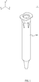
- An embodiment of the mixer 1 of the present invention comprises a hollow and elongate shaped casing 100 and a mixing component 200 disposed in the casing 100.
- One internal end of the casing 100 is provided with an installation portion 101.
- the mixing component 200 is provided with a non-circular mounting portion 201, such that the mounting portion 201 of the mixing component 200 is combined with the installation portion 101, so that the mixing component 200 is stably installed in the casing 100 and prevented from rotating against the casing 100.
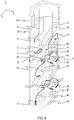
- the mixing component 200 comprises a first vertical wall 10, a second vertical wall 20, an inlet baffle 30, an outlet baffle 40, a plurality of first arc shape guiding plates 50, a plurality of second arc shape guiding plates 60, and a plurality of connection baffles 80.
- the first vertical wall 10 and the second vertical wall 20 are disposed in opposite and in parallel to each other.
- the inlet baffle 30 is disposed on one end of the first vertical wall 10 and the second vertical wall 20, and at the same time disposed adjacent to the mounting portion 201.
- the inlet baffle 30 is formed in an arc shape and extends from the second vertical wall 20 to the mounting portion 201.
- the inlet baffle 30 separated the two to-be-mixed materials into two streams.
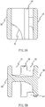
- a drop portion 31 is disposed on one side of the inlet baffle 30, as shown in Fig. 5 A .
- the outlet baffle 40 is disposed on the other end of the first vertical wall 10 and the second vertical wall 20.
- An outlet portion 41 is disposed on one side of the outlet baffle 40, while the other side thereof provided with two guiding outlets 42 disposed in opposite.
- the two guiding outlets 42 and the outlet portion 41 are applied for guiding the streams to flow out and be exported from a distal end of the casing 100, as shown in Fig. 5 B .
- the plural first arc shape guiding plates 50 and second arc shape guiding plates 60 are mutually spaced and disposed in opposite between the inlet baffle 30 and the outlet baffle 40, such that the stream passing through forms a whirlpool.
- the first arc shape guiding plates 50 extend from the first vertical wall 10 toward the outlet baffle 40; the second arc shape guiding plates 60 extend from the second vertical wall 20 toward the inlet baffle 30, and at the same time extends toward the same direction as the inlet baffle 30 does.
- a platform 70 is formed between a free end of the first arc shape guiding plate 50 and the second vertical wall 20.
- One side of the second arc shape guiding plate 60 is provided with a gap 61.
- the other side of the second arc shape guiding plate 60 is provided with a first path 62, through where the streams pass. Also, an arc-shaped connection portion 63 is disposed between the second arc shape guiding plate 60 and the first vertical wall 10. The connection portion 63 laterally extends toward a next first arc shape guiding plate 50.
- connection baffles 80 are equidistantly and transversely disposed from the inlet baffle 30 toward the outlet baffle 40, and at the same time disposed on the upper side and the lower side of each two corresponding first arc shape guiding plate 50 and second arc shape guiding plate 60. Also, one of the connection baffles 80 is disposed between the first arc shape guiding plate 50 adjacent to the mounting portion 201 and the inlet baffle 30, and one of the connection baffles 80 is disposed between the second arc shape guiding plate 60 which is the most far away from the mounting portion 201 and the outlet baffle 40. A second path 71 is disposed between the connection baffle 80 and the corresponding platform 70.
- each corresponding first arc shape guiding plate 50 and the second arc shape guiding plate 60 are connected by a side guiding plate 90, and the side guiding plate 90 is connected between the first vertical wall 10 and the second vertical wall 20.
- the side guiding plate 90 is provided with an edge 91, wherein a horizontal height of the edge 91 is higher than the free end of the second arc shape guiding plate 60.
- the edge 91 of the side guiding plate 90 and the free end of the second arc shape guiding plate 60 form a cross shape, such that the passing stream is separated.
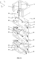
- the inlet baffle 30 separates the two to-be-mixed materials into a first stream A and a second steam B for flowing to the outlet baffle 40.
- the first stream A directly flows to the first arc shape guiding plate 50.
- the second stream B flows through the drop portion 31 of the inlet baffle 30 to the platform 70.
- the first stream A is blocked by the connection baffle 80 and is separated into a first branch stream A1 and a second branch stream A2 which flow to two sides of the mixing component 200, respectively.
- the first branch stream A1 and the second stream B gather as a whirlpool and form an initial mixed stream C, which then passes through the second path 71 and flow to the second arc shape guiding plate 60.
- the initial mixed stream C After the initial mixed stream C passes through the second path 71, the initial mixed stream C is further mixed with the second branch stream A2 and form a mixed stream D, which gathers as a whirlpool on one side of the second arc shape guiding plate 60 and reaches the side guiding plate 90.
- the mixed stream D spills over the edge 91 and flows to the next first arc shape guiding plate 50, wherein a part of the mixed stream D flows through the gap 61 of the second arc shape guiding plate 60 to the next first arc shape guiding plate 50; another part of the mixed stream D flows through the first path 62 to the next first arc shape guiding plate 50; the other part of the mixed stream D flows through the side guiding plate 90 to the first arc shape guiding plate 50.
- the mixed stream D is again guided and separated by the first arc shape guiding plate 50 and the second arc shape guiding plate 60, so as to form a whirlpool mixing with pressure difference, thereby sufficiently and completely mix the two to-be-mixed materials. Furthermore, by use of the first path 62 and the second path 71, the two to-be-mixed materials repeatedly flow through the two sides and both the left and right parts of the mixing component 200, accelerating the mixing process.
- the mixed stream D is flowing out or exported from the outlet portion 41 and the guiding outlet 42 of the outlet baffle 40 in a sufficiently mixed status. Also, unnecessary waste of the materials is prevented.
Landscapes
- Chemical & Material Sciences (AREA)
- Dispersion Chemistry (AREA)
- Chemical Kinetics & Catalysis (AREA)
Claims (9)
- Mélangeur (1) pour mélanger deux matières devant être mélangées, le mélangeur (1) comprenant un boîtier (100) et un composant de mélange (200), le composant de mélange (200) comprenant :une première paroi verticale (10) et une seconde paroi verticale (20) disposée de manière opposée et parallèle à la première paroi verticale (10) ;un déflecteur d'entrée (30) disposé sur une extrémité de la première paroi verticale (10) et de la seconde paroi verticale (20), le déflecteur d'entrée (30) séparant les deux matières devant être mélangées en deux courants ;un déflecteur de sortie (40) disposé sur l'autre extrémité de la première paroi verticale (10) et de la seconde paroi verticale (20), le déflecteur de sortie (40) exportant les courants ; etune pluralité de premières plaques de guidage en forme d'arc (50) et de secondes plaques de guidage en forme d'arc (60) disposées entre le déflecteur d'entrée (30) et le déflecteur de sortie (40), les premières plaques de guidage en forme d'arc (50) et les secondes plaques de guidage en forme d'arc (60) étant mutuellement espacées et disposées de manière opposée ;chaque seconde plaque de guidage en forme d'arc (60) a un côté de celle-ci comportant un intervalle (61) et l'autre côté de celle-ci comportant un premier trajet (62) à travers lequel les courants passent ;caractérisé par le fait que les premières plaques de guidage en forme d'arc (50) s'étendent à partir de la première paroi verticale (10) vers le déflecteur de sortie (40), les secondes plaques de guidage en forme d'arc (60) s'étendent à partir de la seconde paroi verticale (20) vers le déflecteur d'entrée (30).
- Mélangeur selon la revendication 1, dans lequel le déflecteur d'entrée (30) s'étend à partir de la seconde paroi verticale (20), et le déflecteur d'entrée (30) et la seconde plaque de guidage en forme d'arc (60) s'étendent vers la même direction.
- Mélangeur selon la revendication 2, dans lequel un côté du déflecteur d'entrée (30) comporte une partie chute (31).
- Mélangeur selon la revendication 1, dans lequel une plate-forme (70) est formée entre une extrémité libre de la première plaque de guidage en forme d'arc (50) et la seconde paroi verticale (20).
- Mélangeur selon la revendication 4, comprenant en outre plusieurs déflecteurs de liaison (80) qui sont disposés à équidistance à partir du déflecteur d'entrée (30) vers le déflecteur de sortie (40) ; un second trajet (71) est disposé entre le déflecteur de liaison (80) et la plate-forme correspondante (70).
- Mélangeur selon la revendication 1, dans lequel chaque première plaque de guidage en forme d'arc (50) correspondante et la seconde plaque de guidage en forme d'arc (60) sont reliées par une plaque de guidage latérale (90).
- Mélangeur selon la revendication 6, dans lequel une partie de liaison en forme d'arc (63) est disposée entre la seconde plaque de guidage en forme d'arc (60) et la première paroi latérale (10).
- Mélangeur selon la revendication 1, dans lequel le composant de mélange (200) comporte une partie de montage non-circulaire (201) disposée adjacente au déflecteur d'entrée (30), et le boîtier (100) comporte une partie d'installation (101) destinée à être combinée à la partie de montage (201).
- Mélangeur selon la revendication 1, dans lequel un côté du déflecteur de sortie (40) comporte une partie de sortie (41) et l'autre côté du déflecteur de sortie (40) comporte deux sorties de guidage (42).
Applications Claiming Priority (1)
| Application Number | Priority Date | Filing Date | Title |
|---|---|---|---|
| PCT/CN2014/079717 WO2015188340A1 (fr) | 2014-06-12 | 2014-06-12 | Mélangeur |
Publications (3)
| Publication Number | Publication Date |
|---|---|
| EP3156121A1 EP3156121A1 (fr) | 2017-04-19 |
| EP3156121A4 EP3156121A4 (fr) | 2018-01-24 |
| EP3156121B1 true EP3156121B1 (fr) | 2020-07-29 |
Family
ID=54832718
Family Applications (1)
| Application Number | Title | Priority Date | Filing Date |
|---|---|---|---|
| EP14894349.1A Not-in-force EP3156121B1 (fr) | 2014-06-12 | 2014-06-12 | Mélangeur |
Country Status (6)
| Country | Link |
|---|---|
| US (1) | US10040039B2 (fr) |
| EP (1) | EP3156121B1 (fr) |
| CN (1) | CN106659992B (fr) |
| DE (1) | DE112014000256T5 (fr) |
| ES (1) | ES2811725T3 (fr) |
| WO (1) | WO2015188340A1 (fr) |
Families Citing this family (5)
| Publication number | Priority date | Publication date | Assignee | Title |
|---|---|---|---|---|
| US10328255B2 (en) * | 2016-09-16 | 2019-06-25 | Precision Neurotechnologies Llc | Visual prosthesis employing virtual neural electrode arrays |
| US10722853B2 (en) * | 2017-08-04 | 2020-07-28 | Nordson Corporation | Static mixer without mixing baffle sidewalls and associated mixing conduit |
| CN111111602B (zh) * | 2020-01-20 | 2024-10-29 | 南通微著智能科技有限公司 | 连续流反应模块、反应装置及填块 |
| EP4282516A1 (fr) * | 2022-05-23 | 2023-11-29 | Henkel AG & Co. KGaA | Dispositif et procédé de pulvérisation d'une matière plastique multicomposant |
| CN117016340B (zh) * | 2023-08-08 | 2025-03-14 | 江苏大学 | 一种旋流对撞式流道抗堵塞滴头 |
Family Cites Families (9)
| Publication number | Priority date | Publication date | Assignee | Title |
|---|---|---|---|---|
| US3470912A (en) * | 1966-11-30 | 1969-10-07 | Du Pont | Flow inverter |
| ES2151650T3 (es) * | 1996-07-05 | 2001-01-01 | Sulzer Chemtech Ag | Mezclador estatico. |
| EP1125626B1 (fr) * | 2000-02-17 | 2005-11-02 | Sulzer Chemtech AG | Mélangeur statique |
| US20030048694A1 (en) | 2001-09-12 | 2003-03-13 | Tah Industries Inc. | Material mixing device and method |
| ATE372824T1 (de) | 2002-12-06 | 2007-09-15 | Mixpac Systems Ag | Statischer mischer und verfahren |
| DE10322922A1 (de) * | 2003-05-21 | 2004-12-16 | Fischerwerke Artur Fischer Gmbh & Co. Kg | Statikmischer |
| EP2550089A4 (fr) * | 2010-03-25 | 2014-08-20 | Nordson Corp | Mélangeur statique en-ligne |
| WO2012116873A1 (fr) * | 2011-03-03 | 2012-09-07 | Sulzer Mixpac Ag | Mélangeur statique pour appareil distributeur multicomposant |
| CA2775346C (fr) * | 2011-07-22 | 2019-03-05 | Sulzer Mixpac Ag | Melangeur statique |
-
2014
- 2014-06-12 EP EP14894349.1A patent/EP3156121B1/fr not_active Not-in-force
- 2014-06-12 US US15/308,545 patent/US10040039B2/en active Active
- 2014-06-12 DE DE112014000256.9T patent/DE112014000256T5/de not_active Withdrawn
- 2014-06-12 WO PCT/CN2014/079717 patent/WO2015188340A1/fr not_active Ceased
- 2014-06-12 ES ES14894349T patent/ES2811725T3/es active Active
- 2014-06-12 CN CN201480077172.7A patent/CN106659992B/zh not_active Expired - Fee Related
Non-Patent Citations (1)
| Title |
|---|
| None * |
Also Published As
| Publication number | Publication date |
|---|---|
| EP3156121A1 (fr) | 2017-04-19 |
| US10040039B2 (en) | 2018-08-07 |
| WO2015188340A1 (fr) | 2015-12-17 |
| US20170056845A1 (en) | 2017-03-02 |
| ES2811725T3 (es) | 2021-03-15 |
| CN106659992B (zh) | 2019-03-29 |
| DE112014000256T5 (de) | 2016-04-07 |
| EP3156121A4 (fr) | 2018-01-24 |
| CN106659992A (zh) | 2017-05-10 |
Similar Documents
| Publication | Publication Date | Title |
|---|---|---|
| US10040039B2 (en) | Mixer | |
| EP3083066B1 (fr) | Systèmes de projection de mousse à distance, générateurs de mousse et unités de rechargement | |
| US1496345A (en) | Apparatus for mixing liquids | |
| CN106659993A (zh) | 静态混合器 | |
| CN105056821B (zh) | 一种对称椭圆弧挡板的十字微混合器 | |
| CN107847885B (zh) | 双壁流移位器挡板和相关联的静态混合器及混合的方法 | |
| JP2018522733A (ja) | 入口混合要素、関連する静的ミキサ、及び、混合方法 | |
| JP2014188436A5 (fr) | ||
| CN105107401A (zh) | 一种对称扇形圆环挡板的十字微混合器 | |
| CN102309932A (zh) | 一种气液混合装置及其使用方法 | |
| EP3446776A3 (fr) | Mélangeur statique sans paroi latérale de déflecteur de mélange et conduit de mélange associé | |
| CN106659945B (zh) | 具有通过使用选择性溶剂的萃取蒸馏来分离烃和/或烃的衍生物的混合物的分离用装置的塔 | |
| US20070205307A1 (en) | Device and method for creating hydrodynamic cavitation in fluids | |
| KR101922535B1 (ko) | 추가 혼합 유닛을 포함하는 혼합 시스템 | |
| JP2010051959A5 (fr) | ||
| CN112188933A (zh) | 用于共注入两种或更多种液体的一体式分配喷嘴及其使用方法 | |
| CN104667776B (zh) | 一种多液体混合装置 | |
| JP6166125B2 (ja) | スリットノズル | |
| CN209451468U (zh) | 一种试样切割设备的排废系统 | |
| CN110756073B (zh) | 一种化工液体分流螺旋对冲混合器 | |
| WO2022200280A8 (fr) | Dispositif d'inactivation continue de virus | |
| JP2002361056A (ja) | 流体混合器 | |
| TWI513505B (zh) | 混合器 | |
| RU2317450C1 (ru) | Жидкостно-газовый струйный аппарат | |
| EP2402676A2 (fr) | Procédé de conduite d'un moyen de chauffe et corps de chauffe à plaques |
Legal Events
| Date | Code | Title | Description |
|---|---|---|---|
| STAA | Information on the status of an ep patent application or granted ep patent |
Free format text: STATUS: THE INTERNATIONAL PUBLICATION HAS BEEN MADE |
|
| PUAI | Public reference made under article 153(3) epc to a published international application that has entered the european phase |
Free format text: ORIGINAL CODE: 0009012 |
|
| STAA | Information on the status of an ep patent application or granted ep patent |
Free format text: STATUS: REQUEST FOR EXAMINATION WAS MADE |
|
| 17P | Request for examination filed |
Effective date: 20161024 |
|
| AK | Designated contracting states |
Kind code of ref document: A1 Designated state(s): AL AT BE BG CH CY CZ DE DK EE ES FI FR GB GR HR HU IE IS IT LI LT LU LV MC MK MT NL NO PL PT RO RS SE SI SK SM TR |
|
| AX | Request for extension of the european patent |
Extension state: BA ME |
|
| DAX | Request for extension of the european patent (deleted) | ||
| A4 | Supplementary search report drawn up and despatched |
Effective date: 20180103 |
|
| RIC1 | Information provided on ipc code assigned before grant |
Ipc: B01F 5/06 20060101AFI20171220BHEP |
|
| GRAP | Despatch of communication of intention to grant a patent |
Free format text: ORIGINAL CODE: EPIDOSNIGR1 |
|
| STAA | Information on the status of an ep patent application or granted ep patent |
Free format text: STATUS: GRANT OF PATENT IS INTENDED |
|
| INTG | Intention to grant announced |
Effective date: 20200217 |
|
| GRAS | Grant fee paid |
Free format text: ORIGINAL CODE: EPIDOSNIGR3 |
|
| GRAA | (expected) grant |
Free format text: ORIGINAL CODE: 0009210 |
|
| STAA | Information on the status of an ep patent application or granted ep patent |
Free format text: STATUS: THE PATENT HAS BEEN GRANTED |
|
| AK | Designated contracting states |
Kind code of ref document: B1 Designated state(s): AL AT BE BG CH CY CZ DE DK EE ES FI FR GB GR HR HU IE IS IT LI LT LU LV MC MK MT NL NO PL PT RO RS SE SI SK SM TR |
|
| REG | Reference to a national code |
Ref country code: CH Ref legal event code: EP |
|
| REG | Reference to a national code |
Ref country code: AT Ref legal event code: REF Ref document number: 1295135 Country of ref document: AT Kind code of ref document: T Effective date: 20200815 |
|
| REG | Reference to a national code |
Ref country code: IE Ref legal event code: FG4D |
|
| REG | Reference to a national code |
Ref country code: DE Ref legal event code: R096 Ref document number: 602014068431 Country of ref document: DE |
|
| REG | Reference to a national code |
Ref country code: CH Ref legal event code: NV Representative=s name: TR-IP CONSULTING LLC, CH |
|
| REG | Reference to a national code |
Ref country code: SE Ref legal event code: TRGR |
|
| REG | Reference to a national code |
Ref country code: LT Ref legal event code: MG4D |
|
| REG | Reference to a national code |
Ref country code: NL Ref legal event code: MP Effective date: 20200729 |
|
| REG | Reference to a national code |
Ref country code: AT Ref legal event code: MK05 Ref document number: 1295135 Country of ref document: AT Kind code of ref document: T Effective date: 20200729 |
|
| PG25 | Lapsed in a contracting state [announced via postgrant information from national office to epo] |
Ref country code: BG Free format text: LAPSE BECAUSE OF FAILURE TO SUBMIT A TRANSLATION OF THE DESCRIPTION OR TO PAY THE FEE WITHIN THE PRESCRIBED TIME-LIMIT Effective date: 20201029 Ref country code: AT Free format text: LAPSE BECAUSE OF FAILURE TO SUBMIT A TRANSLATION OF THE DESCRIPTION OR TO PAY THE FEE WITHIN THE PRESCRIBED TIME-LIMIT Effective date: 20200729 Ref country code: LT Free format text: LAPSE BECAUSE OF FAILURE TO SUBMIT A TRANSLATION OF THE DESCRIPTION OR TO PAY THE FEE WITHIN THE PRESCRIBED TIME-LIMIT Effective date: 20200729 Ref country code: NO Free format text: LAPSE BECAUSE OF FAILURE TO SUBMIT A TRANSLATION OF THE DESCRIPTION OR TO PAY THE FEE WITHIN THE PRESCRIBED TIME-LIMIT Effective date: 20201029 Ref country code: GR Free format text: LAPSE BECAUSE OF FAILURE TO SUBMIT A TRANSLATION OF THE DESCRIPTION OR TO PAY THE FEE WITHIN THE PRESCRIBED TIME-LIMIT Effective date: 20201030 Ref country code: PT Free format text: LAPSE BECAUSE OF FAILURE TO SUBMIT A TRANSLATION OF THE DESCRIPTION OR TO PAY THE FEE WITHIN THE PRESCRIBED TIME-LIMIT Effective date: 20201130 Ref country code: FI Free format text: LAPSE BECAUSE OF FAILURE TO SUBMIT A TRANSLATION OF THE DESCRIPTION OR TO PAY THE FEE WITHIN THE PRESCRIBED TIME-LIMIT Effective date: 20200729 Ref country code: HR Free format text: LAPSE BECAUSE OF FAILURE TO SUBMIT A TRANSLATION OF THE DESCRIPTION OR TO PAY THE FEE WITHIN THE PRESCRIBED TIME-LIMIT Effective date: 20200729 |
|
| PG25 | Lapsed in a contracting state [announced via postgrant information from national office to epo] |
Ref country code: LV Free format text: LAPSE BECAUSE OF FAILURE TO SUBMIT A TRANSLATION OF THE DESCRIPTION OR TO PAY THE FEE WITHIN THE PRESCRIBED TIME-LIMIT Effective date: 20200729 Ref country code: RS Free format text: LAPSE BECAUSE OF FAILURE TO SUBMIT A TRANSLATION OF THE DESCRIPTION OR TO PAY THE FEE WITHIN THE PRESCRIBED TIME-LIMIT Effective date: 20200729 Ref country code: PL Free format text: LAPSE BECAUSE OF FAILURE TO SUBMIT A TRANSLATION OF THE DESCRIPTION OR TO PAY THE FEE WITHIN THE PRESCRIBED TIME-LIMIT Effective date: 20200729 Ref country code: IS Free format text: LAPSE BECAUSE OF FAILURE TO SUBMIT A TRANSLATION OF THE DESCRIPTION OR TO PAY THE FEE WITHIN THE PRESCRIBED TIME-LIMIT Effective date: 20201129 |
|
| REG | Reference to a national code |
Ref country code: ES Ref legal event code: FG2A Ref document number: 2811725 Country of ref document: ES Kind code of ref document: T3 Effective date: 20210315 |
|
| PG25 | Lapsed in a contracting state [announced via postgrant information from national office to epo] |
Ref country code: NL Free format text: LAPSE BECAUSE OF FAILURE TO SUBMIT A TRANSLATION OF THE DESCRIPTION OR TO PAY THE FEE WITHIN THE PRESCRIBED TIME-LIMIT Effective date: 20200729 |
|
| PG25 | Lapsed in a contracting state [announced via postgrant information from national office to epo] |
Ref country code: CZ Free format text: LAPSE BECAUSE OF FAILURE TO SUBMIT A TRANSLATION OF THE DESCRIPTION OR TO PAY THE FEE WITHIN THE PRESCRIBED TIME-LIMIT Effective date: 20200729 Ref country code: DK Free format text: LAPSE BECAUSE OF FAILURE TO SUBMIT A TRANSLATION OF THE DESCRIPTION OR TO PAY THE FEE WITHIN THE PRESCRIBED TIME-LIMIT Effective date: 20200729 Ref country code: EE Free format text: LAPSE BECAUSE OF FAILURE TO SUBMIT A TRANSLATION OF THE DESCRIPTION OR TO PAY THE FEE WITHIN THE PRESCRIBED TIME-LIMIT Effective date: 20200729 Ref country code: RO Free format text: LAPSE BECAUSE OF FAILURE TO SUBMIT A TRANSLATION OF THE DESCRIPTION OR TO PAY THE FEE WITHIN THE PRESCRIBED TIME-LIMIT Effective date: 20200729 Ref country code: SM Free format text: LAPSE BECAUSE OF FAILURE TO SUBMIT A TRANSLATION OF THE DESCRIPTION OR TO PAY THE FEE WITHIN THE PRESCRIBED TIME-LIMIT Effective date: 20200729 |
|
| REG | Reference to a national code |
Ref country code: DE Ref legal event code: R097 Ref document number: 602014068431 Country of ref document: DE |
|
| PG25 | Lapsed in a contracting state [announced via postgrant information from national office to epo] |
Ref country code: AL Free format text: LAPSE BECAUSE OF FAILURE TO SUBMIT A TRANSLATION OF THE DESCRIPTION OR TO PAY THE FEE WITHIN THE PRESCRIBED TIME-LIMIT Effective date: 20200729 |
|
| PLBE | No opposition filed within time limit |
Free format text: ORIGINAL CODE: 0009261 |
|
| STAA | Information on the status of an ep patent application or granted ep patent |
Free format text: STATUS: NO OPPOSITION FILED WITHIN TIME LIMIT |
|
| PG25 | Lapsed in a contracting state [announced via postgrant information from national office to epo] |
Ref country code: SK Free format text: LAPSE BECAUSE OF FAILURE TO SUBMIT A TRANSLATION OF THE DESCRIPTION OR TO PAY THE FEE WITHIN THE PRESCRIBED TIME-LIMIT Effective date: 20200729 |
|
| 26N | No opposition filed |
Effective date: 20210430 |
|
| PG25 | Lapsed in a contracting state [announced via postgrant information from national office to epo] |
Ref country code: SI Free format text: LAPSE BECAUSE OF FAILURE TO SUBMIT A TRANSLATION OF THE DESCRIPTION OR TO PAY THE FEE WITHIN THE PRESCRIBED TIME-LIMIT Effective date: 20200729 |
|
| REG | Reference to a national code |
Ref country code: DE Ref legal event code: R079 Ref document number: 602014068431 Country of ref document: DE Free format text: PREVIOUS MAIN CLASS: B01F0005060000 Ipc: B01F0025400000 |
|
| PGFP | Annual fee paid to national office [announced via postgrant information from national office to epo] |
Ref country code: CH Payment date: 20210701 Year of fee payment: 8 |
|
| PG25 | Lapsed in a contracting state [announced via postgrant information from national office to epo] |
Ref country code: MC Free format text: LAPSE BECAUSE OF FAILURE TO SUBMIT A TRANSLATION OF THE DESCRIPTION OR TO PAY THE FEE WITHIN THE PRESCRIBED TIME-LIMIT Effective date: 20200729 |
|
| REG | Reference to a national code |
Ref country code: BE Ref legal event code: MM Effective date: 20210630 |
|
| PG25 | Lapsed in a contracting state [announced via postgrant information from national office to epo] |
Ref country code: LU Free format text: LAPSE BECAUSE OF NON-PAYMENT OF DUE FEES Effective date: 20210612 |
|
| PG25 | Lapsed in a contracting state [announced via postgrant information from national office to epo] |
Ref country code: IE Free format text: LAPSE BECAUSE OF NON-PAYMENT OF DUE FEES Effective date: 20210612 |
|
| PG25 | Lapsed in a contracting state [announced via postgrant information from national office to epo] |
Ref country code: BE Free format text: LAPSE BECAUSE OF NON-PAYMENT OF DUE FEES Effective date: 20210630 |
|
| PGFP | Annual fee paid to national office [announced via postgrant information from national office to epo] |
Ref country code: SE Payment date: 20220617 Year of fee payment: 9 Ref country code: IT Payment date: 20220623 Year of fee payment: 9 Ref country code: GB Payment date: 20220628 Year of fee payment: 9 |
|
| PGFP | Annual fee paid to national office [announced via postgrant information from national office to epo] |
Ref country code: FR Payment date: 20220630 Year of fee payment: 9 |
|
| PGFP | Annual fee paid to national office [announced via postgrant information from national office to epo] |
Ref country code: ES Payment date: 20220705 Year of fee payment: 9 |
|
| REG | Reference to a national code |
Ref country code: CH Ref legal event code: PL |
|
| PG25 | Lapsed in a contracting state [announced via postgrant information from national office to epo] |
Ref country code: LI Free format text: LAPSE BECAUSE OF NON-PAYMENT OF DUE FEES Effective date: 20220630 Ref country code: CH Free format text: LAPSE BECAUSE OF NON-PAYMENT OF DUE FEES Effective date: 20220630 |
|
| PG25 | Lapsed in a contracting state [announced via postgrant information from national office to epo] |
Ref country code: HU Free format text: LAPSE BECAUSE OF FAILURE TO SUBMIT A TRANSLATION OF THE DESCRIPTION OR TO PAY THE FEE WITHIN THE PRESCRIBED TIME-LIMIT; INVALID AB INITIO Effective date: 20140612 |
|
| P01 | Opt-out of the competence of the unified patent court (upc) registered |
Effective date: 20230516 |
|
| PG25 | Lapsed in a contracting state [announced via postgrant information from national office to epo] |
Ref country code: CY Free format text: LAPSE BECAUSE OF FAILURE TO SUBMIT A TRANSLATION OF THE DESCRIPTION OR TO PAY THE FEE WITHIN THE PRESCRIBED TIME-LIMIT Effective date: 20200729 |
|
| PGFP | Annual fee paid to national office [announced via postgrant information from national office to epo] |
Ref country code: DE Payment date: 20230602 Year of fee payment: 10 |
|
| REG | Reference to a national code |
Ref country code: SE Ref legal event code: EUG |
|
| GBPC | Gb: european patent ceased through non-payment of renewal fee |
Effective date: 20230612 |
|
| PG25 | Lapsed in a contracting state [announced via postgrant information from national office to epo] |
Ref country code: MK Free format text: LAPSE BECAUSE OF FAILURE TO SUBMIT A TRANSLATION OF THE DESCRIPTION OR TO PAY THE FEE WITHIN THE PRESCRIBED TIME-LIMIT Effective date: 20200729 Ref country code: GB Free format text: LAPSE BECAUSE OF NON-PAYMENT OF DUE FEES Effective date: 20230612 |
|
| PG25 | Lapsed in a contracting state [announced via postgrant information from national office to epo] |
Ref country code: SE Free format text: LAPSE BECAUSE OF NON-PAYMENT OF DUE FEES Effective date: 20230613 Ref country code: FR Free format text: LAPSE BECAUSE OF NON-PAYMENT OF DUE FEES Effective date: 20230630 |
|
| PG25 | Lapsed in a contracting state [announced via postgrant information from national office to epo] |
Ref country code: TR Free format text: LAPSE BECAUSE OF FAILURE TO SUBMIT A TRANSLATION OF THE DESCRIPTION OR TO PAY THE FEE WITHIN THE PRESCRIBED TIME-LIMIT Effective date: 20200729 |
|
| REG | Reference to a national code |
Ref country code: ES Ref legal event code: FD2A Effective date: 20240730 |
|
| PG25 | Lapsed in a contracting state [announced via postgrant information from national office to epo] |
Ref country code: IT Free format text: LAPSE BECAUSE OF NON-PAYMENT OF DUE FEES Effective date: 20230612 |
|
| PG25 | Lapsed in a contracting state [announced via postgrant information from national office to epo] |
Ref country code: MT Free format text: LAPSE BECAUSE OF FAILURE TO SUBMIT A TRANSLATION OF THE DESCRIPTION OR TO PAY THE FEE WITHIN THE PRESCRIBED TIME-LIMIT Effective date: 20200729 |
|
| PG25 | Lapsed in a contracting state [announced via postgrant information from national office to epo] |
Ref country code: ES Free format text: LAPSE BECAUSE OF NON-PAYMENT OF DUE FEES Effective date: 20230613 |
|
| PG25 | Lapsed in a contracting state [announced via postgrant information from national office to epo] |
Ref country code: ES Free format text: LAPSE BECAUSE OF NON-PAYMENT OF DUE FEES Effective date: 20230613 |
|
| REG | Reference to a national code |
Ref country code: DE Ref legal event code: R119 Ref document number: 602014068431 Country of ref document: DE |
|
| PG25 | Lapsed in a contracting state [announced via postgrant information from national office to epo] |
Ref country code: DE Free format text: LAPSE BECAUSE OF NON-PAYMENT OF DUE FEES Effective date: 20250101 |