EP3156302A1 - Dispositif de climatisation d'un habitacle de véhicule, en particulier un véhicule sur rail - Google Patents
Dispositif de climatisation d'un habitacle de véhicule, en particulier un véhicule sur rail Download PDFInfo
- Publication number
- EP3156302A1 EP3156302A1 EP16193712.3A EP16193712A EP3156302A1 EP 3156302 A1 EP3156302 A1 EP 3156302A1 EP 16193712 A EP16193712 A EP 16193712A EP 3156302 A1 EP3156302 A1 EP 3156302A1
- Authority
- EP
- European Patent Office
- Prior art keywords
- air
- flow
- channel
- temperature
- interior
- Prior art date
- Legal status (The legal status is an assumption and is not a legal conclusion. Google has not performed a legal analysis and makes no representation as to the accuracy of the status listed.)
- Granted
Links
Images
Classifications
-
- B—PERFORMING OPERATIONS; TRANSPORTING
- B61—RAILWAYS
- B61D—BODY DETAILS OR KINDS OF RAILWAY VEHICLES
- B61D27/00—Heating, cooling, ventilating, or air-conditioning
- B61D27/0018—Air-conditioning means, i.e. combining at least two of the following ways of treating or supplying air, namely heating, cooling or ventilating
-
- B—PERFORMING OPERATIONS; TRANSPORTING
- B60—VEHICLES IN GENERAL
- B60H—ARRANGEMENTS OF HEATING, COOLING, VENTILATING OR OTHER AIR-TREATING DEVICES SPECIALLY ADAPTED FOR PASSENGER OR GOODS SPACES OF VEHICLES
- B60H1/00—Heating, cooling or ventilating devices
- B60H1/00357—Air-conditioning arrangements specially adapted for particular vehicles
- B60H1/00371—Air-conditioning arrangements specially adapted for particular vehicles for vehicles carrying large numbers of passengers, e.g. buses
-
- B—PERFORMING OPERATIONS; TRANSPORTING
- B60—VEHICLES IN GENERAL
- B60H—ARRANGEMENTS OF HEATING, COOLING, VENTILATING OR OTHER AIR-TREATING DEVICES SPECIALLY ADAPTED FOR PASSENGER OR GOODS SPACES OF VEHICLES
- B60H1/00—Heating, cooling or ventilating devices
- B60H1/00642—Control systems or circuits; Control members or indication devices for heating, cooling or ventilating devices
- B60H1/00814—Control systems or circuits characterised by their output, for controlling particular components of the heating, cooling or ventilating installation
- B60H1/00821—Control systems or circuits characterised by their output, for controlling particular components of the heating, cooling or ventilating installation the components being ventilating, air admitting or air distributing devices
- B60H1/00828—Ventilators, e.g. speed control
-
- B—PERFORMING OPERATIONS; TRANSPORTING
- B60—VEHICLES IN GENERAL
- B60H—ARRANGEMENTS OF HEATING, COOLING, VENTILATING OR OTHER AIR-TREATING DEVICES SPECIALLY ADAPTED FOR PASSENGER OR GOODS SPACES OF VEHICLES
- B60H3/00—Other air-treating devices
- B60H3/06—Filtering
- B60H2003/0683—Filtering the quality of the filter or the air being checked
-
- Y—GENERAL TAGGING OF NEW TECHNOLOGICAL DEVELOPMENTS; GENERAL TAGGING OF CROSS-SECTIONAL TECHNOLOGIES SPANNING OVER SEVERAL SECTIONS OF THE IPC; TECHNICAL SUBJECTS COVERED BY FORMER USPC CROSS-REFERENCE ART COLLECTIONS [XRACs] AND DIGESTS
- Y02—TECHNOLOGIES OR APPLICATIONS FOR MITIGATION OR ADAPTATION AGAINST CLIMATE CHANGE
- Y02T—CLIMATE CHANGE MITIGATION TECHNOLOGIES RELATED TO TRANSPORTATION
- Y02T30/00—Transportation of goods or passengers via railways, e.g. energy recovery or reducing air resistance
Definitions
- the present invention relates to a method of operating a device for air conditioning an interior of a vehicle.
- a vehicle for example designed as a rail vehicle, can be used for passenger transport.
- the invention relates to a device for air conditioning such a vehicle, wherein the comfort of passengers is increased.
- Air conditioning devices for vehicles are already known from the automotive, rail vehicle and aviation. It is important to be able to influence temperatures indoors of these vehicles and aircraft.
- the WO 2010/145954 A1 describes an air conditioning device, which provides a control based on various temperature sensors.
- the object of the present invention is therefore to provide an improved device for air conditioning an interior of a vehicle, wherein in particular a reliable provision of an air-conditioning air flow is to be ensured.
- the method is used to operate a device for air conditioning an interior of a vehicle.
- the apparatus has a passage for flowing air in a flow direction, with an inlet for sucking air at the beginning and an outlet for blowing air at the end of the passage.
- a filter device for filtering out dust and particles from the air is provided, which, not necessarily, can be arranged directly at the inlet of the channel. This also includes such an arrangement in which the filter device is provided directly or in the region in front of the inlet.
- a heat exchanger device Downstream of the filter device follows, medium or directly, viewed in the direction of flow of the channel, a heat exchanger device for influencing a temperature of the air present in the channel or the air flowing through it.
- the heat exchanger device may be designed for heating and / or cooling.
- a fan delivers air from the inlet to the outlet through the duct.
- the fan is connected downstream in the flow direction of the heat exchanger device. Consequently, the fan sucks ambient air into the inlet of the channel, whereupon the air flow passes through the filter device and is thereby cleaned. Following this, the air flows through the heat exchanger device and reaches the fan.
- the fan is arranged upstream of the heat exchanger device and sucks air through the filter device and further conveys or sucked this sucked air through the heat exchanger device.
- the air or the air flow is conveyed in the direction of the outlet through the channel, wherein a measuring device for determining a mass flow or volume flow of the air flow is arranged upstream of the outlet in the channel.
- the measuring device is thus the heat exchanger device, the fan and the filter device downstream provided in the channel in the flow direction.
- the measuring device is arranged in the region of the outlet of the channel, so that it detects the volume or mass flow which is equal to, in particular similar to, or substantially proportional to the outflow velocity of the air flow directly at or after the outlet. In this way, a conclusion on the air speed in the interior is drawn.
- the method further includes the steps of first determining or specifying a desired volumetric or mass flow of the airflow in the duct or at the outlet of the duct. This may be, for example, a permissible maximum value for the volumetric or mass flow, or also - converted or determined - the outflow velocity of the air flow emerging from the outlet and entering the interior.
- the actual volume or mass flow of the air flow of the air flow is measured through the channel and compared with the target value of the volume flow or mass flow of the air flow.
- the location of the ACTUAL measurement correlates or coincides with the location where the DES target volumetric or mass flow is desired.
- the SOLL volumetric or mass flow represents an actual flow velocity of the effluent airflow at the outlet or air velocity in space
- the determination of the actual volumetric or mass flow of the airflow is at a different location in the duct
- a suitable one To identify and consider the correlation between the volume or mass flow or the flow rate at the outlet or in the interior and the volume or mass flow or the flow velocity at the measuring device.
- the delivery rate or the rotational speed of the fan is set in such a way that the existing actual volume - or mass flow or the actual flow rate equal to the target value of the target volume or mass flow or the target flow rate of the air flow.
- the desired volume or mass flow or the desired flow rate of the air flow through the duct can be selected such that a desired air speed in the interior or outflow speed of the air flow at or directly after the outlet corresponds to certain parameters, in particular does not exceed a maximum value .
- conversion algorithms or conversion tables can be used for this purpose, in particular of the actual volume or mass flow or the actual flow velocity at the location of the measurement or the measuring device in the channel to the real, outflowing volume or mass flow or the real outflow velocity or close to the outlet in the immediate vicinity.
- the dimensioning of heat exchangers for such devices for air conditioning can be lower.
- oversizing the Heat exchangers for example, to provide the cooling capacity at a reduced flow rate or mass flow available, now the reduced flow rate or mass flow can be increased and the required cooling capacity can be provided again. In this way prevents unnecessary power reserves of the heat exchanger device must be kept in order to achieve, for example, a required cooling capacity.
- the value of the volume or mass flow or the flow velocity of the outflowing air flow from the outlet and thus also the air flow located in the interior is limited to a maximum value in the inventive device, so that the comfort of the passengers is not impaired. This is done by the control or regulating unit described above in cooperation with the measuring device in the channel. If, as a result of the operation of the device for air conditioning, its filter device is increasingly added, the associated reduction of the outflow velocity or of the volume or mass flow through the device can be continuously compensated by increasing the fan power. Thus, the air velocity in space can be kept constant and within the comfort parameters regardless of a state of the filter device.
- the measuring device has a mass flow sensor for measuring the mass flow of the air flow in the channel.
- the measuring device for measuring an air mass flow may, for example, be an air mass flow sensor, which is referred to in English as "mass air flow meter" or MAF for short.
- MAF mass air flow meter
- the use of an air mass flow sensor has the advantage that the air mass flow is detected directly and therefore the mass of the air flowing through the channel is used by the control unit as a controlled variable.
- the flow velocity of the air flow is determined in the following. This is done by converting over the density. This can be temperature-dependent as a result of the detection of the temperature at the outlet.
- the use of a mass flow sensor has the advantage that the design of the measuring device in the channel is extremely simple, since mass flow sensors are robust, reliable and cost-effective.
- the air pressure of the air flow in particular determined in advance and / or not measured and evaluated. Since the density of the air flowing through the channel is primarily dependent on the temperature, preferably a first temperature sensor in the channel, preferably in the flow direction downstream of the fan, may be provided.
- the air mass sensor can, for example, operate on the principle of a hot wire anemometer.
- Hot wire anemometers are very reliable, require only a small space and do not have moving parts.
- the measuring device for measuring an air mass flow can therefore also have two or more air mass sensors.
- air mass sensors further offers the advantage that detection must take place only at one point, for example close to the outlet, and e.g. no cross-sectional changes are required, as with differential pressure knives. Controls based on pressure differences require sensors in different areas of the channel, which can also have different temperatures.
- the measuring device can be designed as a flow sensor for determining a volume flow.
- the determination of the flow velocity becomes particularly simple, because pressure and temperature of the air flow in the channel for determining the flow velocity in this case need not necessarily be known. Conceivable for this are direct volumetric or indirect volumetric meters.
- the temperature of the air flow in the channel can be measured by means of the first temperature sensor, wherein the measurement result is used by the control unit to optimally control the heat exchanger device with respect to the need for heat and cooling capacity and the adjustment of the actual temperature to the target -Temperature, especially in the room to make faster. Furthermore, this temperature can serve as a correction factor for the density of the air volume flow.
- the set temperature for the interior is determined or set in a first step.
- the actual temperature in the interior of the vehicle is measured by means of a second, arranged in the interior temperature sensor and compared with the target temperature. Based on a detected difference in the temperatures, the heat or cooling capacity requirement is determined and the heat exchanger devices are controlled via the control unit, so that the actual temperature is equal to the set temperature of the interior.
- the regulation of the temperature can be further improved by measuring the outside temperature by means of a third temperature sensor according to a further embodiment and is used to control the heat exchanger by the control unit.
- a recirculating air channel into an initial region, in particular the air inlet region of the channel, wherein in particular a temperature of the air stream in the recirculating air channel can be measured by means of a fourth temperature sensor.
- a device for air conditioning an interior of a vehicle in particular a rail vehicle
- a channel for guiding and / or conditioning an air flow in a flow direction with an inlet and an outlet for discharging the air flow, in particular via a duct system in the Interior of the vehicle has.
- the channel in turn comprises a filter device, a heat exchanger device, a fan and a measuring device for determining the air mass or volume flow, or the flow velocity of an air flow in the channel.
- the measuring device of the heat exchanger device is provided downstream of the fan and the filter device in the flow direction in the channel or the subsequent supply air duct.
- the device for air conditioning comprises an air conditioner, wherein the channel is arranged in the air conditioner. Downstream of the air conditioner, a supply air duct system for distributing the air to the outlets in the interior of the rail vehicle is provided. Furthermore, the air conditioner upstream of a primary air duct system may be arranged, which connects the inlet of the air conditioner with an inlet on an outer side of the rail vehicle. In this connection, according to a special embodiment, the measuring device can be installed in the downstream supply air duct system.
- the device further comprises a control unit for adjusting the speed or the delivery rate of the fan, which is connected to the measuring device for determining the air volume or mass flow, and thus - taking into account the respective cross section of the channel - the flow rate and is adapted to the above to perform said method or embodiments thereof.
- the control unit must be equipped with appropriate preliminary information and control loops in order to implement the advantageous control as described above.
- the control unit must be equipped with information on ratios of mass flow, volume flow, flow velocity and cross sections of the channel, in particular taking into account temperature and / or disregarding the pressure.
- control unit is embodied in this way or has corresponding conversion algorithms or conversion tables (look-up table) so that an actual volume flow or an actual flow speed of the air flow at the location of the measuring device in the channel can be determined from the measurement results of the measuring device ,
- control unit is designed and set up so that by means of the determined actual volume flow a desired volume flow, or by means of the determined actual flow speed, a desired flow rate of the air through the channel is adjustable.
- the device has a first temperature sensor, which is connected downstream of the fan and, in particular, is arranged upstream of the measuring device in the channel. In order to transmit the measurement signals of the first temperature sensor to the control unit, this is connected to the control unit. Furthermore, the control unit is connected to the heat exchanger device and designed to control the operation of this, so that a temperature of the air flow in the channel or the air flow flowing out of the outlet is adjustable. Thus, it is possible to adjust both outflow velocity and temperature of the airflow flowing out of the outlet in a simultaneous manner and independently of the condition of the filter device. This leads to increased comfort of the passengers in the interior of the vehicle.
- Another embodiment discloses that in the interior of the vehicle, a second temperature sensor is attached, which is connected by transmission means for transmitting measurement signals to the control unit. This leads to a further improvement of the control of the device, since the temperature state in the interior of the vehicle can be used to control the air flow.
- a third temperature sensor on the outside of the vehicle, which is connected by means of transmission means with the control unit.
- the information on the outside of the vehicle temperature leads to a further improvement of the control of the device, and is used in particular for adjusting the performance of the heat exchanger device.
- the invention proposes to provide a recirculating air duct for supplying air from the interior to the device, in particular in the flow direction in a region of the channel in front of the filter device.
- the airflow flowing out of the outlet and flowing into the interior air flow can be completely or partially formed by air from the interior.
- the energy consumption when cooling or heating the air flow can be reduced when the temperature level of the recirculated air already corresponds to the desired temperature.
- the heat exchanger device is designed as a combined heating and / or cooling device, preferably as a single unit, which makes it possible to cool the air flow as well as to heat and to allow a particularly wide temperature spectrum. It is also conceivable that such functions are performed by a plurality of different heat exchanger devices, wherein an evaporator for cooling the air flow and / or a heater for heating the air flow is provided in the channel. Preferably, the heating device and the cooling device are arranged directly next to each other in the channel.
- the described embodiments of the method and described embodiments of the device to compensate for and counteract negative effects of contamination of the filter device and / or the heat exchanger device.
- the use of the method and the device in connection with passenger transport vehicle causes an increase in the comfort of the passengers concerned.
- contamination of components of the device for air conditioning takes place continuously, but during which passengers are constantly affected.
- a reduction in the supply air volume flow can lead to non-compliance with the required climatic conditions.
- too large a supply air volume flow is perceived as drafts in the interior and must be avoided. This finding made it possible for the first time to advantageously use the described embodiments of the method according to the invention.
- a vehicle in particular a rail vehicle, comprising a device for air conditioning according to one or more of the embodiments described above.
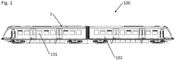
- Fig. 1 shows a rail vehicle 100 with a device 1 for air conditioning an interior 101 of the rail vehicle 100.
- the device 1 may be at least partially disposed in an area of the vehicle roof.
- the operation of the device 1 for air conditioning of the interior 101 of the rail vehicle 100 will be clarified.
- the interior 101 is arranged to receive persons.
- the device 1 for air conditioning is provided substantially within the car body 102.
- the device for air conditioning may be arranged at least partially or completely on the roof outside the car body, on an underfloor area below the car body or in the car body.
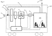
- the device 1 for air conditioning in this case has an air conditioner 15 with a channel 2, which produces an inlet 3, for example outside the car body 102 and an outlet 4 in a downstream channel system for air distribution into the interior 101 and thus a fluidic connection between the environment and the interior 101 ,
- a filter device 5 In the channel 2 or in the air conditioner 15, a filter device 5, a heat exchanger device 6, a fan 7 and a measuring device 8 for measuring a volume or mass flow of a moving air in the channel 2 is arranged.
- the Measuring device 8 can also be installed in the air conditioner 15 downstream air duct system 16. According to the order of enumeration, these individual components are arranged in the flow direction in the channel 2, wherein immediately downstream of the inlet 3, the filter device 5 is provided downstream, followed by the heat exchanger 6, the fan 7 and ultimately of the measuring device.
- a recirculating air channel 9 which fluidly connects the interior 101 with the channel 2, and thus air can be introduced from the interior 101 into a region at the inlet 3 or in the flow direction in front of the filter device 5 in the channel by means of suitable switching elements and ventilation devices , In this way, the air flow in the channel 2 can be completely or partially realized by air from the interior 101.
- the air circulates between the interior 101 and the device 1, whereby the interior 1 has no fluidic connection to the environment. This can be advantageous, for example, to protect the passengers from exposure to polluted air in a tunnel passage.
- the device 1 comprises a control unit 10, wherein the control unit 10 is formed and connected to the heat exchanger device 6 and the fan 7 so that a cooling or heating power of the heat exchanger device 6 and / or a capacity or speed of the fan 7 by the control unit 10 can be adjusted.
- the actual value of the air mass flow, the volume flow or the flow velocity of the air flow in the channel 2 or air duct system 16 is measured and passed on to the control unit 10.
- the measurement of the flow velocity can be carried out via the volume flow or the mass flow or by means of other measuring methods.
- the control unit 10 may be equipped with conversion algorithms or conversion tables to the real value from the measured mass of mass flow at the location of the measuring device 8 Flow rate directly on or just behind the outlet 4 or air speed in space 101 to close.
- the control unit 10 is set so that the air velocity in the interior 101 or flow velocity of the air flow directly at the outlet 4 a does not exceed certain maximum value. If during the use of the device 1, the filter device 5 increasingly polluted, the flow resistance increases by this. This reduces the volume flow in the channel 2, which in turn can be determined by the measuring device 8. According to this reduction, the control unit 10 increases the flow rate or speed of the fan 7 to compensate for the increased flow resistance through the clogged filter device 5. This ensures that in each case sufficient air flow can be introduced into the interior 101 of the rail vehicle 100, which is required for the generation of specifically the cooling capacity.
- thermosensors are provided, and depending on the embodiment, these may also be used individually or in combination. All measurement signals of the temperature sensors are forwarded to the control unit 10 and can thus be used to control the heat exchanger device 6.
- a first temperature sensor 11 is arranged in the channel 2, in particular in the region of the air conditioning unit 15, in order to be able to record the temperature of the air flow in the duct 2 or air conditioner 15.
- the control includes the ability to adjust the temperature of the air flow in the channel 2, and thus also the outflowing air flow, by means of the heat exchanger device 6.
- the first temperature sensor 11 is preferably arranged directly or in the immediate vicinity of the measuring device 8.
- the temperature in the interior 101 is measured by a second temperature sensor 12, so that the real situation in the area of the passengers can be recorded and used for temperature control.
- a third temperature sensor 13 is provided on an outer side of the car body 102 of the rail vehicle 100.
- the temperature in the recirculating air channel 9 are measured by means of a fourth temperature sensor 14 and passed to the control unit 10.
- the knowledge of the temperature in the recirculating air channel 9 causes a temperature of the flowing into the inner space 101 a flowing air flow, for example, by mixing air from the environment and from the interior 101 can be adjusted.
Landscapes
- Engineering & Computer Science (AREA)
- Mechanical Engineering (AREA)
- Physics & Mathematics (AREA)
- Thermal Sciences (AREA)
- Air-Conditioning For Vehicles (AREA)
Applications Claiming Priority (1)
| Application Number | Priority Date | Filing Date | Title |
|---|---|---|---|
| DE102015117665.3A DE102015117665A1 (de) | 2015-10-16 | 2015-10-16 | Vorrichtung zum klimatisieren eines innenraums eines fahrzeugs, insbesondere eines schienenfahrzeugs |
Publications (2)
| Publication Number | Publication Date |
|---|---|
| EP3156302A1 true EP3156302A1 (fr) | 2017-04-19 |
| EP3156302B1 EP3156302B1 (fr) | 2020-07-08 |
Family
ID=57178260
Family Applications (1)
| Application Number | Title | Priority Date | Filing Date |
|---|---|---|---|
| EP16193712.3A Active EP3156302B1 (fr) | 2015-10-16 | 2016-10-13 | Dispositif de climatisation d'un habitacle d'un véhicule ferroviaire |
Country Status (2)
| Country | Link |
|---|---|
| EP (1) | EP3156302B1 (fr) |
| DE (1) | DE102015117665A1 (fr) |
Cited By (5)
| Publication number | Priority date | Publication date | Assignee | Title |
|---|---|---|---|---|
| CN108413548A (zh) * | 2018-05-11 | 2018-08-17 | 苏州大学 | 一种地铁车厢置换通风装置及控制方法 |
| CN110949428A (zh) * | 2019-12-09 | 2020-04-03 | 交控科技股份有限公司 | 列车空调参数调节方法及系统 |
| CN115279604A (zh) * | 2020-03-10 | 2022-11-01 | 捷温有限责任公司 | 用于运行调温鼓风机的方法 |
| EP4494968A1 (fr) * | 2023-07-17 | 2025-01-22 | SpeedInnov | Habitacle ventilé assurant un débit d'air constant |
| WO2025045410A1 (fr) * | 2023-08-30 | 2025-03-06 | Siemens Mobility GmbH | Dispositif de climatisation pour un véhicule lié à une voie |
Families Citing this family (2)
| Publication number | Priority date | Publication date | Assignee | Title |
|---|---|---|---|---|
| DE102017223338B3 (de) | 2017-12-20 | 2019-04-25 | Siemens Aktiengesellschaft | Fahrzeug mit Temperaturregelung für den Fahrgastinnenraum |
| DE102021102517B4 (de) | 2021-02-03 | 2022-12-08 | Carl Freudenberg Kg | Verfahren und Vorrichtung zum Betreiben einer Lüftungsanlage für Luft in einem Innenraum |
Citations (9)
| Publication number | Priority date | Publication date | Assignee | Title |
|---|---|---|---|---|
| JPS5682624A (en) * | 1979-12-07 | 1981-07-06 | Nippon Denso Co Ltd | Controlling device for blower of air-conditioning device for automobile |
| US4518032A (en) * | 1981-11-11 | 1985-05-21 | Hitachi, Ltd. | Temperature control apparatus for automobile air-conditioning systems |
| EP0326044A2 (fr) * | 1988-01-23 | 1989-08-02 | MAN GHH Schienenverkehrstechnik GmbH | Dispositif d'elimination des poussées brusques de pression atmosphérique dans les voitures ferroviaires |
| EP0570288A1 (fr) * | 1992-05-14 | 1993-11-18 | Valeo Thermique Habitacle | Dispositif de ventilation de l'habitacle d'un véhicule |
| DE19847504C1 (de) * | 1998-10-15 | 2000-11-16 | Deutsche Bahn Ag | Verfahren zur Steuerung der Luftvolumenströme in einer raumlufttechnischen Anlage |
| US20060130497A1 (en) | 2004-12-20 | 2006-06-22 | Carrier Corporation | Method and control for testing air filter condition in HVAC system |
| WO2010145954A1 (fr) | 2009-06-15 | 2010-12-23 | Bombardier Transportation Gmbh | Véhicule sur rails présentant un dispositif de climatisation |
| DE102010032636A1 (de) * | 2010-07-29 | 2012-02-02 | Daimler Ag | Belüftungseinrichtung und Verfahren zum Einstellen einer Belüftungseinrichtung für ein Fahrzeug |
| WO2012103641A1 (fr) * | 2011-02-04 | 2012-08-09 | Bombardier Transportation Gmbh | Système de ventilation pour un véhicule de transport de passagers |
Family Cites Families (2)
| Publication number | Priority date | Publication date | Assignee | Title |
|---|---|---|---|---|
| DE10036502C1 (de) * | 2000-07-27 | 2002-04-18 | Behr Hella Thermocontrol Gmbh | Klimaanlage für ein Fahrzeug |
| DE10316294B4 (de) * | 2003-04-09 | 2006-06-14 | Siemens Ag | Verfahren zur Steuerung/Regelung einer Klimaanlage für ein Kraftfahrzeug |
-
2015
- 2015-10-16 DE DE102015117665.3A patent/DE102015117665A1/de not_active Ceased
-
2016
- 2016-10-13 EP EP16193712.3A patent/EP3156302B1/fr active Active
Patent Citations (9)
| Publication number | Priority date | Publication date | Assignee | Title |
|---|---|---|---|---|
| JPS5682624A (en) * | 1979-12-07 | 1981-07-06 | Nippon Denso Co Ltd | Controlling device for blower of air-conditioning device for automobile |
| US4518032A (en) * | 1981-11-11 | 1985-05-21 | Hitachi, Ltd. | Temperature control apparatus for automobile air-conditioning systems |
| EP0326044A2 (fr) * | 1988-01-23 | 1989-08-02 | MAN GHH Schienenverkehrstechnik GmbH | Dispositif d'elimination des poussées brusques de pression atmosphérique dans les voitures ferroviaires |
| EP0570288A1 (fr) * | 1992-05-14 | 1993-11-18 | Valeo Thermique Habitacle | Dispositif de ventilation de l'habitacle d'un véhicule |
| DE19847504C1 (de) * | 1998-10-15 | 2000-11-16 | Deutsche Bahn Ag | Verfahren zur Steuerung der Luftvolumenströme in einer raumlufttechnischen Anlage |
| US20060130497A1 (en) | 2004-12-20 | 2006-06-22 | Carrier Corporation | Method and control for testing air filter condition in HVAC system |
| WO2010145954A1 (fr) | 2009-06-15 | 2010-12-23 | Bombardier Transportation Gmbh | Véhicule sur rails présentant un dispositif de climatisation |
| DE102010032636A1 (de) * | 2010-07-29 | 2012-02-02 | Daimler Ag | Belüftungseinrichtung und Verfahren zum Einstellen einer Belüftungseinrichtung für ein Fahrzeug |
| WO2012103641A1 (fr) * | 2011-02-04 | 2012-08-09 | Bombardier Transportation Gmbh | Système de ventilation pour un véhicule de transport de passagers |
Cited By (6)
| Publication number | Priority date | Publication date | Assignee | Title |
|---|---|---|---|---|
| CN108413548A (zh) * | 2018-05-11 | 2018-08-17 | 苏州大学 | 一种地铁车厢置换通风装置及控制方法 |
| CN110949428A (zh) * | 2019-12-09 | 2020-04-03 | 交控科技股份有限公司 | 列车空调参数调节方法及系统 |
| CN115279604A (zh) * | 2020-03-10 | 2022-11-01 | 捷温有限责任公司 | 用于运行调温鼓风机的方法 |
| EP4494968A1 (fr) * | 2023-07-17 | 2025-01-22 | SpeedInnov | Habitacle ventilé assurant un débit d'air constant |
| FR3151383A1 (fr) * | 2023-07-17 | 2025-01-24 | Speedinnov | Habitacle ventilé assurant un débit d’air constant |
| WO2025045410A1 (fr) * | 2023-08-30 | 2025-03-06 | Siemens Mobility GmbH | Dispositif de climatisation pour un véhicule lié à une voie |
Also Published As
| Publication number | Publication date |
|---|---|
| EP3156302B1 (fr) | 2020-07-08 |
| DE102015117665A1 (de) | 2017-04-20 |
Similar Documents
| Publication | Publication Date | Title |
|---|---|---|
| EP3156302B1 (fr) | Dispositif de climatisation d'un habitacle d'un véhicule ferroviaire | |
| DE4031113C2 (fr) | ||
| EP2870414B1 (fr) | Procédé pour le fonctionnement d'un échangeur thermique ainsi qu'installation hvac pour la réalisation du procédé | |
| DE19947567A1 (de) | Vorrichtung zum Klimatisieren in Kraftfahrzeugen | |
| EP0805056A2 (fr) | Conditionnement d'air pour véhicule avec dispositif pour diriger l'air, réglable en fonction du rayonnement solaire | |
| WO2017101896A2 (fr) | Ventilateur de nuque destiné à un siège de véhicule et son procédé de réglage | |
| DE19711031B4 (de) | Heizungs-, Lüftungs- und/oder Klimaanlage mit Leistungsregelung, insbesondere für Kraftfahrzeuge | |
| DE19615239C1 (de) | Verfahren zum Betrieb einer Heizungs- und/oder Klimaanlage | |
| DE112019002360T5 (de) | Blasvorrichtung | |
| DE102017202872B4 (de) | Verfahren und Vorrichtung zur Bestimmung der Ausblastemperaturen einer automatischen Klimaanlage eines Fahrzeugs | |
| EP0385395B1 (fr) | Dispositif de commande pour les lamelles d'un appareil de chauffage d'air, de refroidissement d'air ou d'aération | |
| DE10036502C1 (de) | Klimaanlage für ein Fahrzeug | |
| DE102009023671B4 (de) | Vorrichtung und Verfahren zum Kühlen mindestens einer Batterie | |
| DE10208851B4 (de) | Kraftfahrzeugklimaanlage für den Innenraum eines Transportfahrzeugs | |
| WO2011038883A1 (fr) | Procédé et dispositif de climatisation d'au moins un habitacle de véhicule et une unité de batterie | |
| DE2651232A1 (de) | Kraftfahrzeugheizung | |
| DE19954000A1 (de) | Heizungs- und Lüftungsanlage für Fahrzeuge | |
| DE10304272A1 (de) | Klimaanlage für den Innenraum eines Fahrzeugs | |
| EP3299195B1 (fr) | Procédé de régulation d'une installation de climatisation pour un véhicule | |
| DE19711033A1 (de) | Heizungs-, Lüftungs- und/oder Klimaanlage mit Temperaturregelung, insbesondere für Kraftfahrzeuge | |
| EP1364820B1 (fr) | Dispositif et procédé pour chauffer et/ou aérer l'habitacle d'un véhicule | |
| WO2000063034A1 (fr) | Dispositif de regulation de la temperature a l'interieur d'un vehicule | |
| DE19719287A1 (de) | Klimaanlage für den Innenraum eines Fahrzeuges | |
| DE10036509C1 (de) | Luftauslass für in den Innenraum eines Fahrzeuges einströmende Luft | |
| DE102013014359B4 (de) | Verfahren zur Steuerung einer Fahrzeugklimaanlage eines Fahrzeugs und Fahrzeugklimaanlage zur Durchführung des Verfahrens |
Legal Events
| Date | Code | Title | Description |
|---|---|---|---|
| PUAI | Public reference made under article 153(3) epc to a published international application that has entered the european phase |
Free format text: ORIGINAL CODE: 0009012 |
|
| STAA | Information on the status of an ep patent application or granted ep patent |
Free format text: STATUS: THE APPLICATION HAS BEEN PUBLISHED |
|
| AK | Designated contracting states |
Kind code of ref document: A1 Designated state(s): AL AT BE BG CH CY CZ DE DK EE ES FI FR GB GR HR HU IE IS IT LI LT LU LV MC MK MT NL NO PL PT RO RS SE SI SK SM TR |
|
| AX | Request for extension of the european patent |
Extension state: BA ME |
|
| RAP1 | Party data changed (applicant data changed or rights of an application transferred) |
Owner name: BOMBARDIER TRANSPORTATION GMBH |
|
| STAA | Information on the status of an ep patent application or granted ep patent |
Free format text: STATUS: REQUEST FOR EXAMINATION WAS MADE |
|
| 17P | Request for examination filed |
Effective date: 20171013 |
|
| RBV | Designated contracting states (corrected) |
Designated state(s): AL AT BE BG CH CY CZ DE DK EE ES FI FR GB GR HR HU IE IS IT LI LT LU LV MC MK MT NL NO PL PT RO RS SE SI SK SM TR |
|
| GRAP | Despatch of communication of intention to grant a patent |
Free format text: ORIGINAL CODE: EPIDOSNIGR1 |
|
| STAA | Information on the status of an ep patent application or granted ep patent |
Free format text: STATUS: GRANT OF PATENT IS INTENDED |
|
| INTG | Intention to grant announced |
Effective date: 20200127 |
|
| GRAS | Grant fee paid |
Free format text: ORIGINAL CODE: EPIDOSNIGR3 |
|
| GRAA | (expected) grant |
Free format text: ORIGINAL CODE: 0009210 |
|
| STAA | Information on the status of an ep patent application or granted ep patent |
Free format text: STATUS: THE PATENT HAS BEEN GRANTED |
|
| AK | Designated contracting states |
Kind code of ref document: B1 Designated state(s): AL AT BE BG CH CY CZ DE DK EE ES FI FR GB GR HR HU IE IS IT LI LT LU LV MC MK MT NL NO PL PT RO RS SE SI SK SM TR |
|
| REG | Reference to a national code |
Ref country code: CH Ref legal event code: EP Ref country code: AT Ref legal event code: REF Ref document number: 1288140 Country of ref document: AT Kind code of ref document: T Effective date: 20200715 |
|
| REG | Reference to a national code |
Ref country code: DE Ref legal event code: R096 Ref document number: 502016010427 Country of ref document: DE |
|
| REG | Reference to a national code |
Ref country code: IE Ref legal event code: FG4D Free format text: LANGUAGE OF EP DOCUMENT: GERMAN |
|
| REG | Reference to a national code |
Ref country code: CH Ref legal event code: NV Representative=s name: DENNEMEYER AG, CH |
|
| REG | Reference to a national code |
Ref country code: LT Ref legal event code: MG4D |
|
| REG | Reference to a national code |
Ref country code: NL Ref legal event code: MP Effective date: 20200708 |
|
| PG25 | Lapsed in a contracting state [announced via postgrant information from national office to epo] |
Ref country code: FI Free format text: LAPSE BECAUSE OF FAILURE TO SUBMIT A TRANSLATION OF THE DESCRIPTION OR TO PAY THE FEE WITHIN THE PRESCRIBED TIME-LIMIT Effective date: 20200708 Ref country code: PT Free format text: LAPSE BECAUSE OF FAILURE TO SUBMIT A TRANSLATION OF THE DESCRIPTION OR TO PAY THE FEE WITHIN THE PRESCRIBED TIME-LIMIT Effective date: 20201109 Ref country code: LT Free format text: LAPSE BECAUSE OF FAILURE TO SUBMIT A TRANSLATION OF THE DESCRIPTION OR TO PAY THE FEE WITHIN THE PRESCRIBED TIME-LIMIT Effective date: 20200708 Ref country code: BG Free format text: LAPSE BECAUSE OF FAILURE TO SUBMIT A TRANSLATION OF THE DESCRIPTION OR TO PAY THE FEE WITHIN THE PRESCRIBED TIME-LIMIT Effective date: 20201008 Ref country code: ES Free format text: LAPSE BECAUSE OF FAILURE TO SUBMIT A TRANSLATION OF THE DESCRIPTION OR TO PAY THE FEE WITHIN THE PRESCRIBED TIME-LIMIT Effective date: 20200708 Ref country code: GR Free format text: LAPSE BECAUSE OF FAILURE TO SUBMIT A TRANSLATION OF THE DESCRIPTION OR TO PAY THE FEE WITHIN THE PRESCRIBED TIME-LIMIT Effective date: 20201009 Ref country code: NO Free format text: LAPSE BECAUSE OF FAILURE TO SUBMIT A TRANSLATION OF THE DESCRIPTION OR TO PAY THE FEE WITHIN THE PRESCRIBED TIME-LIMIT Effective date: 20201008 Ref country code: HR Free format text: LAPSE BECAUSE OF FAILURE TO SUBMIT A TRANSLATION OF THE DESCRIPTION OR TO PAY THE FEE WITHIN THE PRESCRIBED TIME-LIMIT Effective date: 20200708 Ref country code: SE Free format text: LAPSE BECAUSE OF FAILURE TO SUBMIT A TRANSLATION OF THE DESCRIPTION OR TO PAY THE FEE WITHIN THE PRESCRIBED TIME-LIMIT Effective date: 20200708 |
|
| PG25 | Lapsed in a contracting state [announced via postgrant information from national office to epo] |
Ref country code: PL Free format text: LAPSE BECAUSE OF FAILURE TO SUBMIT A TRANSLATION OF THE DESCRIPTION OR TO PAY THE FEE WITHIN THE PRESCRIBED TIME-LIMIT Effective date: 20200708 Ref country code: LV Free format text: LAPSE BECAUSE OF FAILURE TO SUBMIT A TRANSLATION OF THE DESCRIPTION OR TO PAY THE FEE WITHIN THE PRESCRIBED TIME-LIMIT Effective date: 20200708 Ref country code: RS Free format text: LAPSE BECAUSE OF FAILURE TO SUBMIT A TRANSLATION OF THE DESCRIPTION OR TO PAY THE FEE WITHIN THE PRESCRIBED TIME-LIMIT Effective date: 20200708 Ref country code: IS Free format text: LAPSE BECAUSE OF FAILURE TO SUBMIT A TRANSLATION OF THE DESCRIPTION OR TO PAY THE FEE WITHIN THE PRESCRIBED TIME-LIMIT Effective date: 20201108 |
|
| PG25 | Lapsed in a contracting state [announced via postgrant information from national office to epo] |
Ref country code: NL Free format text: LAPSE BECAUSE OF FAILURE TO SUBMIT A TRANSLATION OF THE DESCRIPTION OR TO PAY THE FEE WITHIN THE PRESCRIBED TIME-LIMIT Effective date: 20200708 |
|
| REG | Reference to a national code |
Ref country code: DE Ref legal event code: R097 Ref document number: 502016010427 Country of ref document: DE |
|
| PG25 | Lapsed in a contracting state [announced via postgrant information from national office to epo] |
Ref country code: RO Free format text: LAPSE BECAUSE OF FAILURE TO SUBMIT A TRANSLATION OF THE DESCRIPTION OR TO PAY THE FEE WITHIN THE PRESCRIBED TIME-LIMIT Effective date: 20200708 Ref country code: SM Free format text: LAPSE BECAUSE OF FAILURE TO SUBMIT A TRANSLATION OF THE DESCRIPTION OR TO PAY THE FEE WITHIN THE PRESCRIBED TIME-LIMIT Effective date: 20200708 Ref country code: CZ Free format text: LAPSE BECAUSE OF FAILURE TO SUBMIT A TRANSLATION OF THE DESCRIPTION OR TO PAY THE FEE WITHIN THE PRESCRIBED TIME-LIMIT Effective date: 20200708 Ref country code: DK Free format text: LAPSE BECAUSE OF FAILURE TO SUBMIT A TRANSLATION OF THE DESCRIPTION OR TO PAY THE FEE WITHIN THE PRESCRIBED TIME-LIMIT Effective date: 20200708 Ref country code: IT Free format text: LAPSE BECAUSE OF FAILURE TO SUBMIT A TRANSLATION OF THE DESCRIPTION OR TO PAY THE FEE WITHIN THE PRESCRIBED TIME-LIMIT Effective date: 20200708 Ref country code: EE Free format text: LAPSE BECAUSE OF FAILURE TO SUBMIT A TRANSLATION OF THE DESCRIPTION OR TO PAY THE FEE WITHIN THE PRESCRIBED TIME-LIMIT Effective date: 20200708 |
|
| PLBE | No opposition filed within time limit |
Free format text: ORIGINAL CODE: 0009261 |
|
| STAA | Information on the status of an ep patent application or granted ep patent |
Free format text: STATUS: NO OPPOSITION FILED WITHIN TIME LIMIT |
|
| PG25 | Lapsed in a contracting state [announced via postgrant information from national office to epo] |
Ref country code: AL Free format text: LAPSE BECAUSE OF FAILURE TO SUBMIT A TRANSLATION OF THE DESCRIPTION OR TO PAY THE FEE WITHIN THE PRESCRIBED TIME-LIMIT Effective date: 20200708 |
|
| 26N | No opposition filed |
Effective date: 20210409 |
|
| GBPC | Gb: european patent ceased through non-payment of renewal fee |
Effective date: 20201013 |
|
| PG25 | Lapsed in a contracting state [announced via postgrant information from national office to epo] |
Ref country code: MC Free format text: LAPSE BECAUSE OF FAILURE TO SUBMIT A TRANSLATION OF THE DESCRIPTION OR TO PAY THE FEE WITHIN THE PRESCRIBED TIME-LIMIT Effective date: 20200708 Ref country code: LU Free format text: LAPSE BECAUSE OF NON-PAYMENT OF DUE FEES Effective date: 20201013 Ref country code: SK Free format text: LAPSE BECAUSE OF FAILURE TO SUBMIT A TRANSLATION OF THE DESCRIPTION OR TO PAY THE FEE WITHIN THE PRESCRIBED TIME-LIMIT Effective date: 20200708 |
|
| REG | Reference to a national code |
Ref country code: BE Ref legal event code: MM Effective date: 20201031 |
|
| PG25 | Lapsed in a contracting state [announced via postgrant information from national office to epo] |
Ref country code: BE Free format text: LAPSE BECAUSE OF NON-PAYMENT OF DUE FEES Effective date: 20201031 Ref country code: SI Free format text: LAPSE BECAUSE OF FAILURE TO SUBMIT A TRANSLATION OF THE DESCRIPTION OR TO PAY THE FEE WITHIN THE PRESCRIBED TIME-LIMIT Effective date: 20200708 Ref country code: GB Free format text: LAPSE BECAUSE OF NON-PAYMENT OF DUE FEES Effective date: 20201013 |
|
| PG25 | Lapsed in a contracting state [announced via postgrant information from national office to epo] |
Ref country code: IE Free format text: LAPSE BECAUSE OF NON-PAYMENT OF DUE FEES Effective date: 20201013 |
|
| PG25 | Lapsed in a contracting state [announced via postgrant information from national office to epo] |
Ref country code: TR Free format text: LAPSE BECAUSE OF FAILURE TO SUBMIT A TRANSLATION OF THE DESCRIPTION OR TO PAY THE FEE WITHIN THE PRESCRIBED TIME-LIMIT Effective date: 20200708 Ref country code: MT Free format text: LAPSE BECAUSE OF FAILURE TO SUBMIT A TRANSLATION OF THE DESCRIPTION OR TO PAY THE FEE WITHIN THE PRESCRIBED TIME-LIMIT Effective date: 20200708 Ref country code: CY Free format text: LAPSE BECAUSE OF FAILURE TO SUBMIT A TRANSLATION OF THE DESCRIPTION OR TO PAY THE FEE WITHIN THE PRESCRIBED TIME-LIMIT Effective date: 20200708 |
|
| PG25 | Lapsed in a contracting state [announced via postgrant information from national office to epo] |
Ref country code: MK Free format text: LAPSE BECAUSE OF FAILURE TO SUBMIT A TRANSLATION OF THE DESCRIPTION OR TO PAY THE FEE WITHIN THE PRESCRIBED TIME-LIMIT Effective date: 20200708 |
|
| P01 | Opt-out of the competence of the unified patent court (upc) registered |
Effective date: 20230822 |
|
| REG | Reference to a national code |
Ref country code: CH Ref legal event code: U11 Free format text: ST27 STATUS EVENT CODE: U-0-0-U10-U11 (AS PROVIDED BY THE NATIONAL OFFICE) Effective date: 20251101 |
|
| PGFP | Annual fee paid to national office [announced via postgrant information from national office to epo] |
Ref country code: DE Payment date: 20251021 Year of fee payment: 10 |
|
| PGFP | Annual fee paid to national office [announced via postgrant information from national office to epo] |
Ref country code: AT Payment date: 20251022 Year of fee payment: 10 |
|
| PGFP | Annual fee paid to national office [announced via postgrant information from national office to epo] |
Ref country code: FR Payment date: 20251030 Year of fee payment: 10 |
|
| PGFP | Annual fee paid to national office [announced via postgrant information from national office to epo] |
Ref country code: CH Payment date: 20251101 Year of fee payment: 10 |