EP3157123B1 - Atténuation de l'effet d'une panne en aval dans un système de commutation de transfert automatique - Google Patents
Atténuation de l'effet d'une panne en aval dans un système de commutation de transfert automatique Download PDFInfo
- Publication number
- EP3157123B1 EP3157123B1 EP16155417.5A EP16155417A EP3157123B1 EP 3157123 B1 EP3157123 B1 EP 3157123B1 EP 16155417 A EP16155417 A EP 16155417A EP 3157123 B1 EP3157123 B1 EP 3157123B1
- Authority
- EP
- European Patent Office
- Prior art keywords
- load
- switch
- power source
- electrical current
- failure
- Prior art date
- Legal status (The legal status is an assumption and is not a legal conclusion. Google has not performed a legal analysis and makes no representation as to the accuracy of the status listed.)
- Active
Links
Images



Classifications
-
- H—ELECTRICITY
- H02—GENERATION; CONVERSION OR DISTRIBUTION OF ELECTRIC POWER
- H02J—ELECTRIC POWER NETWORKS; CIRCUIT ARRANGEMENTS OR SYSTEMS FOR SUPPLYING OR DISTRIBUTING ELECTRIC POWER; SYSTEMS FOR STORING ELECTRIC ENERGY
- H02J3/00—Circuit arrangements for AC mains or AC distribution networks
- H02J3/38—Arrangements for feeding a single network from two or more generators or sources in parallel; Arrangements for feeding already energised networks from additional generators or sources in parallel
-
- H—ELECTRICITY
- H02—GENERATION; CONVERSION OR DISTRIBUTION OF ELECTRIC POWER
- H02J—ELECTRIC POWER NETWORKS; CIRCUIT ARRANGEMENTS OR SYSTEMS FOR SUPPLYING OR DISTRIBUTING ELECTRIC POWER; SYSTEMS FOR STORING ELECTRIC ENERGY
- H02J4/00—Circuit arrangements for mains or distribution networks not specified as AC or DC; Circuit arrangements for mains or distribution networks combining AC and DC sections or sub-networks
- H02J4/20—Networks integrating separated AC and DC power sections
- H02J4/25—Networks integrating separated AC and DC power sections for transfer of electric power between AC and DC networks, e.g. for supplying the DC section within a load from an AC mains system
-
- G—PHYSICS
- G06—COMPUTING OR CALCULATING; COUNTING
- G06F—ELECTRIC DIGITAL DATA PROCESSING
- G06F1/00—Details not covered by groups G06F3/00 - G06F13/00 and G06F21/00
- G06F1/26—Power supply means, e.g. regulation thereof
- G06F1/263—Arrangements for using multiple switchable power supplies, e.g. battery and AC
-
- G—PHYSICS
- G06—COMPUTING OR CALCULATING; COUNTING
- G06F—ELECTRIC DIGITAL DATA PROCESSING
- G06F1/00—Details not covered by groups G06F3/00 - G06F13/00 and G06F21/00
- G06F1/26—Power supply means, e.g. regulation thereof
- G06F1/30—Means for acting in the event of power-supply failure or interruption, e.g. power-supply fluctuations
-
- H—ELECTRICITY
- H02—GENERATION; CONVERSION OR DISTRIBUTION OF ELECTRIC POWER
- H02J—ELECTRIC POWER NETWORKS; CIRCUIT ARRANGEMENTS OR SYSTEMS FOR SUPPLYING OR DISTRIBUTING ELECTRIC POWER; SYSTEMS FOR STORING ELECTRIC ENERGY
- H02J4/00—Circuit arrangements for mains or distribution networks not specified as AC or DC; Circuit arrangements for mains or distribution networks combining AC and DC sections or sub-networks
-
- H—ELECTRICITY
- H02—GENERATION; CONVERSION OR DISTRIBUTION OF ELECTRIC POWER
- H02J—ELECTRIC POWER NETWORKS; CIRCUIT ARRANGEMENTS OR SYSTEMS FOR SUPPLYING OR DISTRIBUTING ELECTRIC POWER; SYSTEMS FOR STORING ELECTRIC ENERGY
- H02J9/00—Circuit arrangements for emergency or stand-by power supply, e.g. for emergency lighting
- H02J9/04—Circuit arrangements for emergency or stand-by power supply, e.g. for emergency lighting in which the distribution system is disconnected from the normal source and connected to a standby source
- H02J9/06—Circuit arrangements for emergency or stand-by power supply, e.g. for emergency lighting in which the distribution system is disconnected from the normal source and connected to a standby source with automatic change-over, e.g. UPS systems
-
- G—PHYSICS
- G06—COMPUTING OR CALCULATING; COUNTING
- G06F—ELECTRIC DIGITAL DATA PROCESSING
- G06F1/00—Details not covered by groups G06F3/00 - G06F13/00 and G06F21/00
- G06F1/26—Power supply means, e.g. regulation thereof
-
- H—ELECTRICITY
- H02—GENERATION; CONVERSION OR DISTRIBUTION OF ELECTRIC POWER
- H02M—APPARATUS FOR CONVERSION BETWEEN AC AND AC, BETWEEN AC AND DC, OR BETWEEN DC AND DC, AND FOR USE WITH MAINS OR SIMILAR POWER SUPPLY SYSTEMS; CONVERSION OF DC OR AC INPUT POWER INTO SURGE OUTPUT POWER; CONTROL OR REGULATION THEREOF
- H02M1/00—Details of apparatus for conversion
- H02M1/0003—Details of control, feedback or regulation circuits
- H02M1/0009—Devices or circuits for detecting current in a converter
Definitions
- a load e.g., a network device, a computer, a power supply module, etc.
- a first power source e.g., a power supply module, a generator, a power plant, etc.
- a second power source may function as a backup for the first power source.
- an automatic transfer switching (ATS) system may switch the load from being powered by the first power source to being powered by the second power source.
- ATS automatic transfer switching
- US6601002B1 relates to a control arrangement and method for detecting a responding to disturbances in electrical power systems.
- US2015/0035358A1 relates to an electrical power system and a method of managing electrical power.
- US2015/0035358A1 does not disclose at least a device comprising one or more processors to: determine based on a signal from a sensor included in the load that the failure condition is associated with a failure at the load; and transmit a signal based on determining that the failure condition is associated with the failure at the load, the signal causing the first switch to maintain a state of the first switch when the first switch receives the signal, the state being a first state when the first switch powers the load using the first electrical current, or the state being a second state when the first switch powers the load using the second electrical current to prevent a power source for the load associated with the failure from being switched from the first power source to the second power source or from the second power source to the first power source.
- An automatic transfer switching (ATS) system may manage a set of power sources (e.g., power supply modules, generators, power plants, etc.) that may provide electrical current to power a load (e.g., a network device, a computer, a power supply module, etc.).
- the load may be described herein as being "downstream" from the set of power sources, and the set of power sources may be described herein as being "upstream” from the load.
- the ATS system may detect the failure, and may switch the load to be powered by a second power source of the set of power sources. In this way, the ATS improves resilience of the load against power failures.
- a failure may occur at the load.
- the load may undergo a short circuit, a line cut scenario, or the like.
- the failure at the load may damage a first upstream power source that powers the load.
- the ATS system may detect the failure, and may automatically switch the load to be powered by a second upstream power source.
- the second upstream power source may be damaged by the failure at the load.
- Implementations described herein permit the ATS system to determine that the failure is associated with the load, based on the failure at the load causing a voltage drop and/or an amperage increase, to perform an action to mitigate damage to the upstream power sources, and to prevent failure of the ATS system.
- the ATS system improves failure resilience of the ATS system and reduces a likelihood of damage to multiple upstream power sources due to a failure associated with a downstream load.
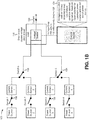
- Figs. 1A-1C are diagrams of an overview of an example implementation 100 described herein.
- Figs. 1A-1C show an ATS system to provide power to a load.
- the ATS system shown in Fig. 1A includes 4 power sources (e.g., power source 1, power source 2, power source 3, and power source 4).
- each power source is connected with a respective switch (e.g., switch 1, switch 2, switch 3, and switch 4, respectively).
- switch 1 and switch 3 are closed (e.g., permitting electrical current to pass), and switch 2 and switch 4 are open (e.g., not permitting electrical current to pass).
- power sources 1-4 and switches 1-4 may communicate with a control device of the ATS system.
- the control device may control power sources 1-4 and switches 1-4.
- the control device may open or close switches, may activate power sources, may deactivate power sources, may cause a power source to change a voltage and/or amperage of an electrical current provided by the power source, or the like.
- power sources 1-4 are associated with current sensors (e.g., current sensor 1, current sensor 2, current sensor 3, and current sensor 4).
- Current sensors 1-4 may detect amperages of electrical currents supplied by power sources 1-4, and may provide information identifying the amperages to the control device, as shown by reference number 110.
- the ATS system may include switch 5 to switch the load between power sources 1 and 2, and switch 6 to switch the load between power sources 3 and 4.
- switch 5 and switch 6 may communicate with the control device.
- the control device may control switches 5-6. When the control device detects a failure of a power source, the control device may use switch 5 and/or switch 6 to switch the downstream load to a different power source.
- control device may switch the downstream load to power source 2 by actuating switch 1 (e.g., to open the line from power source 1 to switch 5), switch 2 (e.g., to close the line from power source 2 to switch 5), and/or switch 5 (e.g., to open the line from power source 1 to the load, and to close the line from power source 2 to the load).
- switch 1 e.g., to open the line from power source 1 to switch 5
- switch 2 e.g., to close the line from power source 2 to switch 5
- switch 5 e.g., to open the line from power source 1 to the load, and to close the line from power source 2 to the load.
- Switch 5 and switch 6 may operate in a particular state. For example, when switch 5 is closed with regard to power source 1, switch 5 may be in a first state, and when switch 5 is closed with regard to power source 2, switch 5 may be in a second state.
- the control device may control the states of switch 5 and switch 6.
- the load for the ATS system may include a voltage sensor.
- the voltage sensor may measure voltages of the electrical currents provided by power sources 1-4 at the load.
- the voltage sensor may provide information to the control device (e.g., information identifying voltages of the electrical currents, information identifying changes in voltages of the electrical currents, etc.).
- the load may output an electrical current that may be generating using power from the electrical currents received from power sources 1-4.
- a short circuit at the load may cause a voltage drop at the load, which the voltage sensor may sense.
- the short circuit may interrupt an electrical current outputted by the load.
- the voltage sensor may provide information to the control device indicating that the load has experienced a voltage drop of 250 volts in 1.8 milliseconds (ms). In such a scenario, power source 1 and/or power source 3 may be damaged based on the short circuit at the load.
- the ATS system may cause power source 2 and/or power source 4 to be damaged.
- the control device may determine that the voltage drop satisfies a threshold value (e.g., a voltage change of 200 volts, etc.) and occurs within a threshold amount of time (e.g., 1.8 ms). As further shown, based on the voltage drop at the load satisfying the threshold value and/or occurring within the particular period of time, the control device may detect a load failure condition.
- the load failure condition is caused by the short circuit at the load.
- the control device may cause switches for the upstream power sources to be opened (e.g., switch 1, switch 2, switch 3, and switch 4). As shown by reference number 128, the control device may cause a state of switch 5 and switch 6 to be maintained, to prevent switch 5 and switch 6 from switching the power source for the load from power source 1 to power source 2, and from power source 3 to power source 4, respectively. In some implementations, the control device may open switch 5 and switch 6, to interrupt the electrical currents of power sources 1 and 3, thus preventing damage to power sources 1 and 3. In this way, the control device prevents damage to the upstream power sources caused by a short circuit at the load, which reduces expense associated with maintaining the upstream power sources and improves resilience of the ATS system.
- switches for the upstream power sources e.g., switch 1, switch 2, switch 3, and switch 4
- the control device may cause a state of switch 5 and switch 6 to be maintained, to prevent switch 5 and switch 6 from switching the power source for the load from power source 1 to power source 2, and from power source 3 to power source 4, respectively.
- a short circuit at the load may cause an increase in amperage (e.g., a current spike) at an upstream power source.
- current sensor 3 associated with power source 3 provides an amperage measurement to the control device indicating that amperage has increased from 80 amps to 900 amps in 1.3 ms.
- the control device may determine that the current spike satisfies a threshold value (e.g., ten times an average load, etc.), and occurs within a threshold amount of time (e.g., 1.8 ms or less, in this case).
- a threshold value e.g., ten times an average load, etc.
- control device may determine that the current spike satisfies a load failure condition based on the current spike satisfying the threshold value and occurring within the particular period of time, and may disconnect power sources 1, 2, 3, and 4 by opening switches 1 and 3, as shown by reference number 136. As further shown, the control device may not switch the load from power source 1 to power source 2, and may not switch the load from power source 3 to power source 4 (e.g., may cause switch 5 and switch 6 to maintain their respective states). In this way, the control device prevents damage to the upstream power sources based on detecting a failure at the load, which reduces expense associated with repairing the upstream power sources and improves resilience of the ATS system.
- Fig. 2 is a diagram of an example environment 200 in which systems and/or methods, described herein, may be implemented.
- environment 200 may include one or more sensors 210-1 through 210-M (M ⁇ 1) (hereinafter referred to collectively as “sensors 210,” and individually as “sensor 210"), a load 220, one or more switches 230-1 through 230-N (N ⁇ 1) (hereinafter referred to collectively as “switches 230,” and individually as “switch 230”), one or more power sources 240-1 through 240-P (P ⁇ 1) (hereinafter referred to collectively as “power sources 240,” and individually as “power source 240”), and a control device 250.
- Devices of environment 200 may interconnect via wired connections, wireless connections, or a combination of wired and wireless connections.
- Fig. 2 shows five sensors 210, six switches 230, and four power sources 240.
- environment 200 may include a different quantity and/or arrangement of sensors 210, loads 220, switches 230, and/or power sources 240.
- types of devices of environment 200 that may communicate are connected by a dashed line.
- a dashed line between sensor 210-4 and control device 250 indicates that control device 250 is capable of communicating with sensors 210-1, 210-2, 210-3, 210-4, and 210-5.
- Sensor 210 may include a device capable of detecting a voltage value and/or an amperage value of an electrical current.
- sensor 210 may include a current sensor, a voltage sensor, an impedance sensor, or the like.
- sensor 210 may be associated with (e.g., included in, placed downstream from, etc.) power source 240.
- sensor 210-5 is included in load 220.
- a sensor may be associated with (e.g. placed downstream from, etc) load 220.
- sensor 210 may receive information from and/or transmit information to another device of environment 200.
- Load 220 may include a device that receives power from power source 240.
- load 220 may include a user device (e.g., a desktop computer, a laptop computer, a mobile device, a gaming device, etc.), a network device (e.g., a router, a gateway, a firewall, a server, an access point, etc.), a bulk capacitor, an appliance, a vehicle, a piece of industrial equipment, a power supply module, or another type of device.
- load 220 may receive information from and/or transmit information to another device of environment 200.
- Switch 230 may include a device capable of interrupting an electrical current and/or diverting an electrical current from a first line to a second line.
- switch 230 may include a relay (e.g., a mechanical relay, a solid-state relay, etc.), a circuit breaker, a fuse, a power transistor, a silicon-controlled rectifier, a bi-directional switch, a triode for alternating current, or the like.
- switch 230 may receive information from and/or transmit information to another device of environment 200.
- Power source 240 may include a device capable of providing electrical current.
- power source 240 may include an alternating current (AC) power supply module, a direct current (DC) power supply module, a power plant, a generator, or the like.
- power source 240 may include one or more sensors 210 and/or switches 230.
- power source 240 may receive information from and/or transmit information to another device of environment 200.
- Control device 250 may include a device capable of receiving, generating, storing, processing, and/or providing information.
- control device 250 may include an integrated circuit, an application-specific integrated circuit, a processor, a control circuit, a field programmable gate array (FPGA), or another type of device that is capable of controlling operation of switches 230.
- control device 250 may receive information from and/or transmit information to another device of environment 200.
- the number and arrangement of devices and networks shown in Fig. 2 are provided as an example. In practice, there may be additional devices and/or networks, fewer devices and/or networks, different devices and/or networks, or differently arranged devices and/or networks than those shown in Fig. 2 . Furthermore, two or more devices shown in Fig. 2 may be implemented within a single device, or a single device shown in Fig. 2 may be implemented as multiple, distributed devices. Additionally, or alternatively, a set of devices (e.g., one or more devices) of environment 200 may perform one or more functions described as being performed by another set of devices of environment 200.
- Fig. 3 is a diagram of example components of a device 300.
- Device 300 may correspond to sensor 210, load 220, switch 230, power source 240, and/or control device 250.
- sensor 210, load 220, switch 230, power source 240, and/or control device 250 may include one or more devices 300 and/or one or more components of device 300.
- device 300 may include a bus 310, a processor 320, a memory 330, a storage component 340, an input component 350, an output component 360, and a communication interface 370.
- Bus 310 may include a component that permits communication among the components of device 300.
- Processor 320 is implemented in hardware, firmware, or a combination of hardware and software.
- Processor 320 may include a processor (e.g., a central processing unit (CPU), a graphics processing unit (GPU), an accelerated processing unit (APU), etc.), a microprocessor, and/or any processing component (e.g., a field-programmable gate array (FPGA), an application-specific integrated circuit (ASIC), etc.) that interprets and/or executes instructions.
- processor 320 may include one or more processors that can be programmed to perform a function.
- Memory 330 may include a random access memory (RAM), a read only memory (ROM), and/or another type of dynamic or static storage device (e.g., a flash memory, a magnetic memory, an optical memory, etc.) that stores information and/or instructions for use by processor 320.
- RAM random access memory
- ROM read only memory
- static storage device e.g., a flash memory, a magnetic memory, an optical memory, etc.
- Storage component 340 may store information and/or software related to the operation and use of device 300.
- storage component 340 may include a hard disk (e.g., a magnetic disk, an optical disk, a magneto-optic disk, a solid state disk, etc.), a compact disc (CD), a digital versatile disc (DVD), a floppy disk, a cartridge, a magnetic tape, and/or another type of computer-readable medium, along with a corresponding drive.
- Input component 350 may include a component that permits device 300 to receive information, such as via user input (e.g., a touch screen display, a keyboard, a keypad, a mouse, a button, a switch, a microphone, etc.). Additionally, or alternatively, input component 350 may include a sensor for sensing information (e.g., a global positioning system (GPS) component, an accelerometer, a gyroscope, an actuator, etc.). Output component 360 may include a component that provides output information from device 300 (e.g., a display, a speaker, one or more light-emitting diodes (LEDs), etc.).
- GPS global positioning system
- LEDs light-emitting diodes
- Communication interface 370 may include a transceiver-like component (e.g., a transceiver, a separate receiver and transmitter, etc.) that enables device 300 to communicate with other devices, such as via a wired connection, a wireless connection, or a combination of wired and wireless connections. Communication interface 370 may permit device 300 to receive information from another device and/or provide information to another device.
- communication interface 370 may include an Ethernet interface, an optical interface, a coaxial interface, an infrared interface, a radio frequency (RF) interface, a universal serial bus (USB) interface, a Wi-Fi interface, a cellular network interface, or the like.
- RF radio frequency
- USB universal serial bus
- Device 300 may perform one or more processes described herein. Device 300 may perform these processes in response to processor 320 executing software instructions stored by a computer-readable medium, such as memory 330 and/or storage component 340.
- a computer-readable medium is defined herein as a transitory or non-transitory memory device.
- a memory device includes memory space within a single physical storage device or memory space spread across multiple physical storage devices.
- Software instructions may be read into memory 330 and/or storage component 340 from another computer-readable medium or from another device via communication interface 370. When executed, software instructions stored in memory 330 and/or storage component 340 may cause processor 320 to perform one or more processes described herein. Additionally, or alternatively, hardwired circuitry may be used in place of or in combination with software instructions to perform one or more processes described herein. Thus, implementations described herein are not limited to any specific combination of hardware circuitry and software.
- device 300 may include additional components, fewer components, different components, or differently arranged components than those shown in Fig. 3 . Additionally, or alternatively, a set of components (e.g., one or more components) of device 300 may perform one or more functions described as being performed by another set of components of device 300.
- a set of components e.g., one or more components
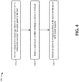
- Fig. 4 is a flow chart of an example process 400 for mitigating an effect of a downstream load failure.
- one or more process blocks of Fig. 4 may be performed by control device 250.
- one or more process blocks of Fig. 4 may be performed by another device or a group of devices separate from or including control device 250, such as sensor 210, load 220, switch 230, and/or power source 240.
- process 400 may include monitoring voltage values and/or amperage values for a load and/or two or more power sources that supply power to the load (block 410).
- control device 250 may monitor voltage values and/or amperage values relating to load 220 and/or one or more power sources 240.
- Control device 250 may monitor the voltage values and/or amperage values based on measurements from sensors 210.
- sensors 210 may detect the voltage values and/or amperage values (e.g., at load 220, at power source 240, downstream from power source 240 and upstream from load 220, etc.), and may provide the voltage values and/or amperage values to control device 250.
- control device 250 may process the voltage values and/or amperage values. For example, control device 250 may determine a moving average of a voltage value and/or an amperage value, a peak voltage value and/or amperage value, a weighted average of a voltage value and/or amperage value, a minimum voltage value and/or amperage value, a root mean square of a voltage value and/or an amperage value, an occurrence of a spike in voltage values and/or amperage values, or the like.
- control device 250 may determine whether an electrical current is routed via a particular path based on the voltage values and/or amperage values. For example, control device 250 may cause an electrical current to be routed via a particular path via operation of switches 230. Control device 250 may obtain information from sensors 210 that are located along the particular path, and may determine whether the electrical current is routed along the particular path. For example, if the information indicates that no electrical current is present on the particular path, control device 250 may cause the electrical current to be rerouted, may cause a worker to be dispatched to the ATS system to determine why no electrical current is present on the particular path, or the like.
- process 400 may include detecting a load failure condition relating to the load (block 420).
- control device 250 may detect a load failure condition relating to load 220.
- a load failure condition may be associated with a failure at load 220, such as a short circuit of load 220, a malfunction of load 220, a failure of load 220 to perform at an expected level, or the like.
- Control device 250 may detect the load failure condition based on voltage values and/or amperage values associated with load 220.
- control device 250 may detect the load failure condition based on a voltage value and/or an amperage value obtained by a sensor 210 that is downstream from power source 240, based on a voltage value and/or an amperage value obtained by sensor 210 that is included in load 220, or the like.
- control device 250 may detect a load failure condition based on an amperage value. For example, control device 250 may detect a load failure condition based on an amperage satisfying a threshold amperage value (e.g., a maximum allowable amperage value, such as 1000% of an expected amperage value, or the like). In this way, control device 250 may determine a load failure condition based on a maximum amperage value, which permits control device 250 to prevent damage to power sources 240 that may be caused by a peak amperage, which reduces expenses associated with maintaining power sources 240.
- a threshold amperage value e.g., a maximum allowable amperage value, such as 1000% of an expected amperage value, or the like.
- control device 250 may detect a load failure condition based on an amperage value satisfying a threshold for a threshold amount of time (e.g., 1000% of an expected amperage value for a period of at least 2 ms, 200% of an expected amperage value for a period of at least 50 ms, etc.). In this way, control device 250 may determine a load failure condition based on an amperage value that is sustained over time, which permits control device 250 to prevent damage to power sources 240 that may be caused by a sustained amperage, and reduces expenses associated with maintaining power sources 240.
- a threshold for a threshold amount of time e.g., 1000% of an expected amperage value for a period of at least 2 ms, 200% of an expected amperage value for a period of at least 50 ms, etc.
- control device 250 may detect a load failure condition based on a change in amperage (e.g., a change from a first amperage value to a second amperage value, a change from a first amperage value to a second amperage value in a threshold amount of time, a percent change in an amperage value, etc.).
- a change in amperage e.g., a change from a first amperage value to a second amperage value, a change from a first amperage value to a second amperage value in a threshold amount of time, a percent change in an amperage value, etc.
- control device 250 may detect a load failure condition based on a voltage value. For example, control device 250 may detect a load failure condition based on a voltage satisfying a threshold voltage value (e.g., a minimum voltage value, such as 80 volts, 25% of an expected voltage value, or the like). In this way, control device 250 may determine a load failure condition based on a sudden drop in voltage at load 220, which permits control device 250 to prevent damage to power sources 240 that may be caused by a peak voltage, and reduces expenses associated with maintaining power sources 240.
- a threshold voltage value e.g., a minimum voltage value, such as 80 volts, 25% of an expected voltage value, or the like.
- control device 250 may detect a load failure condition based on a voltage value satisfying a threshold for a threshold amount of time (e.g., 25% of an expected voltage value for a period of at least 2 ms, less than or equal to 50 volts for a period of 50 ms, etc.). In this way, control device 250 may determine a load failure condition based on a voltage value that is sustained over time, which permits control device 250 to prevent damage to power sources 240 that may be caused by a sustained voltage drop, and reduces expenses associated with maintaining power sources 240.
- a threshold for a threshold amount of time e.g., 25% of an expected voltage value for a period of at least 2 ms, less than or equal to 50 volts for a period of 50 ms, etc.
- control device 250 may detect a load failure condition based on a change in voltage (e.g., a change from a first voltage value to a second voltage value, a change from a first voltage value to a second voltage value in a threshold amount of time, a percent change in a voltage value, etc.). By detecting the load failure condition based on the change in voltage, control device 250 prevents damage to power sources 240 based on rapid changes in voltage at load 220, which reduces expenses associated with maintaining power sources 240.
- a change in voltage e.g., a change from a first voltage value to a second voltage value, a change from a first voltage value to a second voltage value in a threshold amount of time, a percent change in a voltage value, etc.
- control device 250 may detect a load failure condition based on a combination of a voltage value and an amperage value. For example, in some cases, a voltage value and an amperage value for load 220 may change at different times (e.g., the amperage value may increase before the voltage value decreases, the voltage value may decrease before the amperage value increases, etc.). In such cases, control device 250 may detect the change in the voltage value and the change in the amperage value, and may detect a load failure condition accordingly.
- control device 250 may detect a first change in one value (e.g., a voltage value or an amperage value), and may begin monitoring for a subsequent change in the other value (e.g., an amperage value or a voltage value). In this way, control device 250 monitors load 220 for failures based on amperage values and voltage values, which increases likelihood of detecting a load failure condition and, thus, saves time and money used for maintaining power sources 240.
- a first change in one value e.g., a voltage value or an amperage value
- a subsequent change in the other value e.g., an amperage value or a voltage value
- control device 250 may determine a threshold for a load failure condition. For example, control device 250 may obtain voltage values and/or amperage values for the ATS system, and may determine expected voltage values and/or amperage values based on the obtained voltage values and/or amperage values. Control device 250 may determine thresholds for the voltage values and/or amperage values based on the expected voltage values and/or amperage values.
- control device 250 may determine to detect a load failure condition based on a threshold amperage value and a threshold amount of time (e.g., when an amperage value of an electrical current associated with switch 230 increases to more than 1000% of an expected amperage value in less than 1.8 milliseconds, in less than 100 microseconds, etc.).
- control device 250 may determine to detect a load failure condition when a voltage value associated with load 220 decreases to satisfy a threshold value (e.g., decreases to 80 volts, decreases by 250 volts in a particular period of time, etc.).
- process 400 may include performing an action to mitigate an effect of the failure on the two or more upstream power sources (block 430).
- control device 250 may perform an action to mitigate an effect of the failure on power sources 240.
- control device 250 may transmit a signal to another device, to cause the other device to perform an action.
- control device 250 may transmit a failure message to power source 240 to cause power source 240 to stop providing an electrical current to load 220 or to cause power source 240 to modify the electrical current, may provide a failure message to a user device for the user device to provide to a user, or the like.
- control device 250 may cause switch 230 to perform an action. For example, control device 250 may cause switch 230 to interrupt an electrical current, may cause switch 230 to maintain a state of switch 230 (e.g., not to switch load 220 from a first power source 240 to a second power source 240), or the like. In this way, control device 250 mitigates an effect of a downstream failure (e.g., a short circuit) at load 220 on power sources 240, which improves resilience of the system and reduces expense associated with repairing the power sources 240.
- a downstream failure e.g., a short circuit
- control device 250 may cause all switches 230 to interrupt the respective electrical currents with which they are connected. Additionally, or alternatively, control device 250 may cause a subset of the switches 230 to open (e.g., switches 1 and 3 in Figs 1A-1C ), and other switches 230 to maintain a current open/closed state (e.g., switches 5 and 6 in Figs 1A-1C ). Additionally, or alternatively, control device 250 may re-route power based on the load failure condition. For example, control device 250 may actuate one or more switches 230 to power load 220 from a different power source 240 based on the load failure condition (e.g., a cheaper power source 240, a more resilient power source 240, etc.). In this way, control device 250 mitigates an effect of a downstream failure (e.g., a short circuit) at load 220 on power sources 240, which improves resilience of the system and reduces expense associated with repairing the power sources 240.
- a downstream failure e.g.,
- process 400 may include additional blocks, fewer blocks, different blocks, or differently arranged blocks than those depicted in Fig. 4 . Additionally, or alternatively, two or more of the blocks of process 400 may be performed in parallel.
- an ATS system improves failure resilience of the ATS system and reduces a likelihood of damage to multiple upstream power sources due to a failure associated with a downstream load.
- a system may comprise a first switch connected to an output of a first power source, a second switch connected to an output of a second power source, a first sensor connected to an output of the first switch, a second sensor connected to an output of the second switch, a third switch connected to the first sensor and the second sensor and connected to a load, and a control device connected to the first switch, the second switch, the first sensor, the second sensor, and the third switch.
- the term component is intended to be broadly construed as hardware, firmware, and/or a combination of hardware and software.
- satisfying a threshold may refer to a value being greater than the threshold, more than the threshold, higher than the threshold, greater than or equal to the threshold, less than the threshold, fewer than the threshold, lower than the threshold, less than or equal to the threshold, equal to the threshold, etc.
Landscapes
- Engineering & Computer Science (AREA)
- Power Engineering (AREA)
- Theoretical Computer Science (AREA)
- Business, Economics & Management (AREA)
- Emergency Management (AREA)
- General Physics & Mathematics (AREA)
- General Engineering & Computer Science (AREA)
- Physics & Mathematics (AREA)
- Remote Monitoring And Control Of Power-Distribution Networks (AREA)
- Power Sources (AREA)
- Hardware Redundancy (AREA)
- Circuit Arrangement For Electric Light Sources In General (AREA)
- Electronic Switches (AREA)
Claims (8)
- Dispositif, comprenant :
un ou plusieurs processeurs configurés pour :détecter une situation de défaillance dans un système qui comporte une charge (114) et au moins quatre sources d'alimentation (102),la charge (114) étant alimentée par le système, etle système comportant au moins deux commutateurs (104) comportant un premier commutateur (104) et un deuxième commutateur (104),le premier commutateur (104) servant à alimenter sélectivement la charge (114) au moyen d'un premier courant électrique fourni par une première source d'alimentation (102) parmi les au moins quatre sources d'alimentation (102) ou au moyen d'un deuxième courant électrique fourni par une deuxième source d'alimentation (102) parmi les au moins quatre sources d'alimentation (102), etle deuxième commutateur (104) causant l'alimentation de la charge (114) au moyen d'un troisième courant électrique ou d'un quatrième courant électrique,
le troisième courant électrique et le quatrième courant électrique étant fournis respectivement par une troisième source d'alimentation (102) et une quatrième source d'alimentation (102) parmi les au moins quatre sources d'alimentation (102) ; etdéterminer, en fonction d'un signal provenant d'un capteur compris dans la charge (114), que la situation de défaillance est associée à une défaillance au niveau de la charge (114) ; etémettre un signal en fonction de la détermination que la situation de défaillance est associée à la défaillance au niveau de la charge (114),le signal causant le maintien du premier commutateur (104) dans un état du premier commutateur (104) lorsque le premier commutateur (104) reçoit le signal,l'état étant un premier état lorsque le premier commutateur (104) alimente la charge (114) au moyen du premier courant électrique, ou l'état étant un deuxième état lorsque le premier commutateur (104) alimente la charge (114) au moyen du deuxième courant électrique afin d'empêcher la commutation d'une source d'alimentation (102) pour la charge (114) associée à la défaillance depuis la première source d'alimentation (102) sur la deuxième source d'alimentation (102) ou depuis la deuxième source d'alimentation (102) sur la première source d'alimentation (102). - Dispositif selon la revendication 1, dans lequel les un ou plusieurs processeurs, lors de la détection de la situation de défaillance, sont configurés pour : détecter la situation de défaillance en fonction d'informations reçues depuis un capteur compris dans la charge, les informations reçues depuis le capteur comportant une valeur de tension et/ou une valeur d'intensité de courant.
- Dispositif selon la revendication 2, dans lequel les un ou plusieurs processeurs, lors de la détection de la situation de défaillance, sont configurés pour :déterminer que la valeur de tension ou la valeur d'intensité de courant satisfait à un seuil,le seuil étant relatif à : une valeur de tension minimale et/ou une valeur de tension maximale et/ou une variation d'une valeur de tension et/ou une valeur d'intensité de courant minimale et/ou une valeur d'intensité de courant maximale et/ou une variation d'une valeur d'intensité de courant et/ou un laps de temps.
- Dispositif selon l'une quelconque des revendications 1 à 3, dans lequel les un ou plusieurs processeurs sont configurés pour : amener un troisième commutateur à interrompre le premier courant électrique et/ou le deuxième courant électrique.
- Dispositif selon l'une quelconque des revendications 1 à 4, dans lequel les un ou plusieurs processeurs sont configurés pour :
amener la première source d'alimentation et/ou la deuxième source d'alimentation à cesser de fournir respectivement le premier courant électrique ou le deuxième courant électrique en fonction de la détermination que la situation de défaillance est associée à la défaillance au niveau de la charge. - Procédé, comprenant :la détection, par un dispositif de commande, d'une situation de défaillance dans un système qui comporte une charge (114) et au moins quatre sources d'alimentation (102),la charge (114) comportant un dispositif à alimenter par le système, etle système comportant au moins un premier commutateur (104) et un deuxième commutateur (104),le premier commutateur (104) fonctionnant dans un premier état ou un deuxième état,le premier commutateur (104), lorsqu'il occupe le premier état, alimentant la charge (114) au moyen d'un premier courant électrique fourni par une première source d'alimentation (102) parmi les au moins quatre sources d'alimentation (102),le premier commutateur (104), lorsqu'il occupe le deuxième état, alimentant la charge (114) au moyen d'un deuxième courant électrique fourni par une deuxième source d'alimentation (102) parmi les au moins quatre sources d'alimentation (102),le premier commutateur (104) occupant le premier état ou le deuxième étant, etle deuxième commutateur (104) causant l'alimentation de la charge (114) au moyen d'un troisième courant électrique ou d'un quatrième courant électrique,le troisième courant électrique et le quatrième courant électrique étant fournis respectivement par une troisième source d'alimentation (102) et une quatrième source d'alimentation parmi les au moins quatre sources d'alimentation (102) ;la détermination, par le dispositif de commande et en fonction d'un signal provenant d'un capteur compris dans la charge (114), que la situation de défaillance est associée à une défaillance au niveau de la charge (114) ; etle maintien, par le dispositif de commande, du premier commutateur (104) dans le premier état ou le deuxième état sans le commuter entre le premier état et le deuxième état en fonction de la détermination que la situation de défaillance est associée à la défaillance au niveau de la charge (114) afin d'empêcher la commutation d'une source d'alimentation (102) pour la charge (114) associée à la défaillance depuis la première source d'alimentation (102) sur la deuxième source d'alimentation (102) ou depuis la deuxième source d'alimentation (102) sur la première source d'alimentation (102).
- Procédé selon la revendication 6, dans lequel la détection de la situation de défaillance comprend en outre :l'obtention d'une mesure à partir d'un ou de plusieurs capteurs,les un ou plusieurs capteurs déterminant la mesure en fonction : du premier courant électrique et/ou du deuxième courant électrique et/ou d'un courant électrique délivré par la charge.
- Procédé selon la revendication 7, comprenant en outre :l'acheminement du premier courant électrique ou du deuxième courant électrique par un chemin particulier ; etla détermination si le premier courant électrique ou bien le deuxième courant électrique est acheminé par le chemin particulier en fonction de la mesure.
Applications Claiming Priority (1)
| Application Number | Priority Date | Filing Date | Title |
|---|---|---|---|
| US14/867,595 US9705337B2 (en) | 2015-09-28 | 2015-09-28 | Mitigating an effect of a downstream failure in an automatic transfer switching system |
Publications (3)
| Publication Number | Publication Date |
|---|---|
| EP3157123A2 EP3157123A2 (fr) | 2017-04-19 |
| EP3157123A3 EP3157123A3 (fr) | 2017-07-12 |
| EP3157123B1 true EP3157123B1 (fr) | 2021-10-13 |
Family
ID=55450981
Family Applications (1)
| Application Number | Title | Priority Date | Filing Date |
|---|---|---|---|
| EP16155417.5A Active EP3157123B1 (fr) | 2015-09-28 | 2016-02-12 | Atténuation de l'effet d'une panne en aval dans un système de commutation de transfert automatique |
Country Status (3)
| Country | Link |
|---|---|
| US (2) | US9705337B2 (fr) |
| EP (1) | EP3157123B1 (fr) |
| CN (1) | CN106558915B (fr) |
Families Citing this family (8)
| Publication number | Priority date | Publication date | Assignee | Title |
|---|---|---|---|---|
| US10936027B2 (en) * | 2015-06-26 | 2021-03-02 | Trilogy Llc | Power distribution system |
| US9705337B2 (en) | 2015-09-28 | 2017-07-11 | Juniper Networks, Inc. | Mitigating an effect of a downstream failure in an automatic transfer switching system |
| US10777998B2 (en) * | 2018-08-02 | 2020-09-15 | GM Global Technology Operations LLC | Circuit for identifying the source of a power fault in a dual power source electrical system |
| US11394201B2 (en) * | 2018-11-26 | 2022-07-19 | Cummins Power Generation Ip, Inc. | Reverse flow automatic transfer switch |
| US11733285B2 (en) * | 2020-06-05 | 2023-08-22 | Alpha Technologies Ltd. | Touch safe DC powering for remote loads |
| CN116195158B (zh) | 2020-08-11 | 2024-09-10 | 安泊半导体公司 | 智能能源监测和选择控制系统 |
| FI20235981A1 (en) * | 2023-09-01 | 2025-03-02 | Elisa Oyj | Computer-implemented method for managing a site of a virtual power plant |
| US20250256549A1 (en) * | 2024-02-09 | 2025-08-14 | Brunswick Corporation | Systems and methods for selecting between powering components of vehicles via first or second power sources |
Citations (1)
| Publication number | Priority date | Publication date | Assignee | Title |
|---|---|---|---|---|
| US20150035358A1 (en) * | 2013-08-05 | 2015-02-05 | Ragingwire Data Centers, Inc. | Electrical power management system and method |
Family Cites Families (7)
| Publication number | Priority date | Publication date | Assignee | Title |
|---|---|---|---|---|
| DE3042415C2 (de) * | 1980-11-11 | 1990-08-02 | AEG-Telefunken Kabelwerke AG, Rheydt, 4050 Mönchengladbach | Schaltung zur Fehlermeldung bei einem über eine elektronische Schalteinrichtung geschalteten Stromverbraucher |
| US4811136A (en) * | 1987-12-24 | 1989-03-07 | Jones Gregory D | Phase controller for processing current and voltage faults |
| CA2280378C (fr) | 1999-04-29 | 2009-05-26 | S&C Electric Company | Montages de detection des perturbations et de reponse aux perturbations dans les systemes d'alimentation electrique |
| FR2941572B1 (fr) * | 2009-01-28 | 2011-05-06 | Jacques Gascuel | Dispositif de surveillance et de protection de l'alimentation d'un appareil electrique et procede de mise en oeuvre de ce dispositif |
| CN103532218A (zh) * | 2013-10-25 | 2014-01-22 | 国家电网公司 | 一种快速双电源切换开关装置及其工作方法 |
| CN104836222B (zh) * | 2014-02-07 | 2019-07-05 | 通用电气公司 | 用作主控制器时断路器内etu中功率管理的方法和设备 |
| US9705337B2 (en) | 2015-09-28 | 2017-07-11 | Juniper Networks, Inc. | Mitigating an effect of a downstream failure in an automatic transfer switching system |
-
2015
- 2015-09-28 US US14/867,595 patent/US9705337B2/en active Active
-
2016
- 2016-02-02 CN CN201610074410.XA patent/CN106558915B/zh active Active
- 2016-02-12 EP EP16155417.5A patent/EP3157123B1/fr active Active
-
2017
- 2017-07-05 US US15/641,613 patent/US10291035B2/en active Active
Patent Citations (1)
| Publication number | Priority date | Publication date | Assignee | Title |
|---|---|---|---|---|
| US20150035358A1 (en) * | 2013-08-05 | 2015-02-05 | Ragingwire Data Centers, Inc. | Electrical power management system and method |
Also Published As
| Publication number | Publication date |
|---|---|
| EP3157123A2 (fr) | 2017-04-19 |
| US20170302085A1 (en) | 2017-10-19 |
| US10291035B2 (en) | 2019-05-14 |
| US20170093166A1 (en) | 2017-03-30 |
| CN106558915B (zh) | 2021-06-25 |
| EP3157123A3 (fr) | 2017-07-12 |
| US9705337B2 (en) | 2017-07-11 |
| CN106558915A (zh) | 2017-04-05 |
Similar Documents
| Publication | Publication Date | Title |
|---|---|---|
| EP3157123B1 (fr) | Atténuation de l'effet d'une panne en aval dans un système de commutation de transfert automatique | |
| EP1804355B1 (fr) | Détection d'un défaut d'arc dans un réseau AC et protection contre celui-ci | |
| US20100042344A1 (en) | System and method for detecting an electrical short across a static switch of an uninterruptible power supply | |
| US11804729B2 (en) | Transfer switch power source selection systems and methods | |
| US11870186B2 (en) | Surge protector with active overload protection | |
| EP1796238B1 (fr) | Détection et protection d'un arc de défaut à courant continu | |
| KR101469356B1 (ko) | 축전지 모듈 제어 시스템 및 그 방법 | |
| KR20150128124A (ko) | 과전류 계전기 | |
| US9871372B2 (en) | Voltage bus protection and isolation device | |
| EP2953229A1 (fr) | Procédé de surveillance et de protection redondante de canaux de génération de puissance de courant alternatif | |
| JP2021015047A (ja) | 放電検出装置及び分電盤 | |
| US10483748B2 (en) | Junction box and network for distributing energy | |
| CN104242445A (zh) | 用于监测断路器操作的系统和方法 | |
| US20180190444A1 (en) | 3 Phase Undervoltage Trip Device and Molded Case Circuit Breaker Therewith | |
| CN110073563A (zh) | 电负载及其连接线路的过电流保护装置 | |
| CN107181235A (zh) | 用于高电流脉冲电源的短路控制 | |
| JP2013070476A (ja) | サージ保護システム、サーバ、雷規模判別方法、及び、プログラム | |
| KR20160007869A (ko) | 자체소모전력 차단 기능이 구비된 배터리 관리 시스템 | |
| US10027106B2 (en) | Power supply unit for the provision of at least one switchable power output | |
| WO2017000965A1 (fr) | Circuit de sécurité, procédé de fonctionnement du circuit de sécurité et moteur à alimentation électrique comportant un circuit de sécurité | |
| KR101929542B1 (ko) | 섬 상태에서 복수 인버터 스테이션이 패시브 컨트롤 모드로 진입하는 것을 억제하는 방법 | |
| KR101582250B1 (ko) | 선로 결함 감시장치 | |
| CN109359006B (zh) | 控制器的监控方法、装置、控制芯片、控制器和空调 | |
| US20170310106A1 (en) | System for detecting and controlling abnormal state of electric signal and method thereof | |
| US10236790B2 (en) | Power supply with detection and notification of exceeded design limits |
Legal Events
| Date | Code | Title | Description |
|---|---|---|---|
| PUAI | Public reference made under article 153(3) epc to a published international application that has entered the european phase |
Free format text: ORIGINAL CODE: 0009012 |
|
| STAA | Information on the status of an ep patent application or granted ep patent |
Free format text: STATUS: THE APPLICATION HAS BEEN PUBLISHED |
|
| AK | Designated contracting states |
Kind code of ref document: A2 Designated state(s): AL AT BE BG CH CY CZ DE DK EE ES FI FR GB GR HR HU IE IS IT LI LT LU LV MC MK MT NL NO PL PT RO RS SE SI SK SM TR |
|
| AX | Request for extension of the european patent |
Extension state: BA ME |
|
| PUAL | Search report despatched |
Free format text: ORIGINAL CODE: 0009013 |
|
| AK | Designated contracting states |
Kind code of ref document: A3 Designated state(s): AL AT BE BG CH CY CZ DE DK EE ES FI FR GB GR HR HU IE IS IT LI LT LU LV MC MK MT NL NO PL PT RO RS SE SI SK SM TR |
|
| AX | Request for extension of the european patent |
Extension state: BA ME |
|
| RIC1 | Information provided on ipc code assigned before grant |
Ipc: G01R 31/08 20060101ALI20170608BHEP Ipc: H02J 9/06 20060101ALI20170608BHEP Ipc: H02J 3/38 20060101AFI20170608BHEP Ipc: H02J 4/00 20060101ALI20170608BHEP |
|
| STAA | Information on the status of an ep patent application or granted ep patent |
Free format text: STATUS: REQUEST FOR EXAMINATION WAS MADE |
|
| 17P | Request for examination filed |
Effective date: 20180112 |
|
| RBV | Designated contracting states (corrected) |
Designated state(s): AL AT BE BG CH CY CZ DE DK EE ES FI FR GB GR HR HU IE IS IT LI LT LU LV MC MK MT NL NO PL PT RO RS SE SI SK SM TR |
|
| STAA | Information on the status of an ep patent application or granted ep patent |
Free format text: STATUS: EXAMINATION IS IN PROGRESS |
|
| 17Q | First examination report despatched |
Effective date: 20180829 |
|
| GRAP | Despatch of communication of intention to grant a patent |
Free format text: ORIGINAL CODE: EPIDOSNIGR1 |
|
| STAA | Information on the status of an ep patent application or granted ep patent |
Free format text: STATUS: GRANT OF PATENT IS INTENDED |
|
| INTG | Intention to grant announced |
Effective date: 20201210 |
|
| GRAJ | Information related to disapproval of communication of intention to grant by the applicant or resumption of examination proceedings by the epo deleted |
Free format text: ORIGINAL CODE: EPIDOSDIGR1 |
|
| STAA | Information on the status of an ep patent application or granted ep patent |
Free format text: STATUS: EXAMINATION IS IN PROGRESS |
|
| GRAP | Despatch of communication of intention to grant a patent |
Free format text: ORIGINAL CODE: EPIDOSNIGR1 |
|
| STAA | Information on the status of an ep patent application or granted ep patent |
Free format text: STATUS: GRANT OF PATENT IS INTENDED |
|
| INTC | Intention to grant announced (deleted) | ||
| INTG | Intention to grant announced |
Effective date: 20210506 |
|
| GRAS | Grant fee paid |
Free format text: ORIGINAL CODE: EPIDOSNIGR3 |
|
| GRAA | (expected) grant |
Free format text: ORIGINAL CODE: 0009210 |
|
| STAA | Information on the status of an ep patent application or granted ep patent |
Free format text: STATUS: THE PATENT HAS BEEN GRANTED |
|
| AK | Designated contracting states |
Kind code of ref document: B1 Designated state(s): AL AT BE BG CH CY CZ DE DK EE ES FI FR GB GR HR HU IE IS IT LI LT LU LV MC MK MT NL NO PL PT RO RS SE SI SK SM TR |
|
| REG | Reference to a national code |
Ref country code: GB Ref legal event code: FG4D |
|
| REG | Reference to a national code |
Ref country code: CH Ref legal event code: EP |
|
| REG | Reference to a national code |
Ref country code: DE Ref legal event code: R096 Ref document number: 602016064811 Country of ref document: DE |
|
| REG | Reference to a national code |
Ref country code: IE Ref legal event code: FG4D |
|
| REG | Reference to a national code |
Ref country code: AT Ref legal event code: REF Ref document number: 1438872 Country of ref document: AT Kind code of ref document: T Effective date: 20211115 |
|
| REG | Reference to a national code |
Ref country code: LT Ref legal event code: MG9D |
|
| REG | Reference to a national code |
Ref country code: NL Ref legal event code: MP Effective date: 20211013 |
|
| REG | Reference to a national code |
Ref country code: AT Ref legal event code: MK05 Ref document number: 1438872 Country of ref document: AT Kind code of ref document: T Effective date: 20211013 |
|
| PG25 | Lapsed in a contracting state [announced via postgrant information from national office to epo] |
Ref country code: RS Free format text: LAPSE BECAUSE OF FAILURE TO SUBMIT A TRANSLATION OF THE DESCRIPTION OR TO PAY THE FEE WITHIN THE PRESCRIBED TIME-LIMIT Effective date: 20211013 Ref country code: LT Free format text: LAPSE BECAUSE OF FAILURE TO SUBMIT A TRANSLATION OF THE DESCRIPTION OR TO PAY THE FEE WITHIN THE PRESCRIBED TIME-LIMIT Effective date: 20211013 Ref country code: FI Free format text: LAPSE BECAUSE OF FAILURE TO SUBMIT A TRANSLATION OF THE DESCRIPTION OR TO PAY THE FEE WITHIN THE PRESCRIBED TIME-LIMIT Effective date: 20211013 Ref country code: BG Free format text: LAPSE BECAUSE OF FAILURE TO SUBMIT A TRANSLATION OF THE DESCRIPTION OR TO PAY THE FEE WITHIN THE PRESCRIBED TIME-LIMIT Effective date: 20220113 Ref country code: AT Free format text: LAPSE BECAUSE OF FAILURE TO SUBMIT A TRANSLATION OF THE DESCRIPTION OR TO PAY THE FEE WITHIN THE PRESCRIBED TIME-LIMIT Effective date: 20211013 |
|
| PG25 | Lapsed in a contracting state [announced via postgrant information from national office to epo] |
Ref country code: IS Free format text: LAPSE BECAUSE OF FAILURE TO SUBMIT A TRANSLATION OF THE DESCRIPTION OR TO PAY THE FEE WITHIN THE PRESCRIBED TIME-LIMIT Effective date: 20220213 Ref country code: SE Free format text: LAPSE BECAUSE OF FAILURE TO SUBMIT A TRANSLATION OF THE DESCRIPTION OR TO PAY THE FEE WITHIN THE PRESCRIBED TIME-LIMIT Effective date: 20211013 Ref country code: PT Free format text: LAPSE BECAUSE OF FAILURE TO SUBMIT A TRANSLATION OF THE DESCRIPTION OR TO PAY THE FEE WITHIN THE PRESCRIBED TIME-LIMIT Effective date: 20220214 Ref country code: PL Free format text: LAPSE BECAUSE OF FAILURE TO SUBMIT A TRANSLATION OF THE DESCRIPTION OR TO PAY THE FEE WITHIN THE PRESCRIBED TIME-LIMIT Effective date: 20211013 Ref country code: NO Free format text: LAPSE BECAUSE OF FAILURE TO SUBMIT A TRANSLATION OF THE DESCRIPTION OR TO PAY THE FEE WITHIN THE PRESCRIBED TIME-LIMIT Effective date: 20220113 Ref country code: NL Free format text: LAPSE BECAUSE OF FAILURE TO SUBMIT A TRANSLATION OF THE DESCRIPTION OR TO PAY THE FEE WITHIN THE PRESCRIBED TIME-LIMIT Effective date: 20211013 Ref country code: LV Free format text: LAPSE BECAUSE OF FAILURE TO SUBMIT A TRANSLATION OF THE DESCRIPTION OR TO PAY THE FEE WITHIN THE PRESCRIBED TIME-LIMIT Effective date: 20211013 Ref country code: HR Free format text: LAPSE BECAUSE OF FAILURE TO SUBMIT A TRANSLATION OF THE DESCRIPTION OR TO PAY THE FEE WITHIN THE PRESCRIBED TIME-LIMIT Effective date: 20211013 Ref country code: GR Free format text: LAPSE BECAUSE OF FAILURE TO SUBMIT A TRANSLATION OF THE DESCRIPTION OR TO PAY THE FEE WITHIN THE PRESCRIBED TIME-LIMIT Effective date: 20220114 Ref country code: ES Free format text: LAPSE BECAUSE OF FAILURE TO SUBMIT A TRANSLATION OF THE DESCRIPTION OR TO PAY THE FEE WITHIN THE PRESCRIBED TIME-LIMIT Effective date: 20211013 |
|
| REG | Reference to a national code |
Ref country code: DE Ref legal event code: R097 Ref document number: 602016064811 Country of ref document: DE |
|
| PG25 | Lapsed in a contracting state [announced via postgrant information from national office to epo] |
Ref country code: SM Free format text: LAPSE BECAUSE OF FAILURE TO SUBMIT A TRANSLATION OF THE DESCRIPTION OR TO PAY THE FEE WITHIN THE PRESCRIBED TIME-LIMIT Effective date: 20211013 Ref country code: SK Free format text: LAPSE BECAUSE OF FAILURE TO SUBMIT A TRANSLATION OF THE DESCRIPTION OR TO PAY THE FEE WITHIN THE PRESCRIBED TIME-LIMIT Effective date: 20211013 Ref country code: RO Free format text: LAPSE BECAUSE OF FAILURE TO SUBMIT A TRANSLATION OF THE DESCRIPTION OR TO PAY THE FEE WITHIN THE PRESCRIBED TIME-LIMIT Effective date: 20211013 Ref country code: EE Free format text: LAPSE BECAUSE OF FAILURE TO SUBMIT A TRANSLATION OF THE DESCRIPTION OR TO PAY THE FEE WITHIN THE PRESCRIBED TIME-LIMIT Effective date: 20211013 Ref country code: DK Free format text: LAPSE BECAUSE OF FAILURE TO SUBMIT A TRANSLATION OF THE DESCRIPTION OR TO PAY THE FEE WITHIN THE PRESCRIBED TIME-LIMIT Effective date: 20211013 Ref country code: CZ Free format text: LAPSE BECAUSE OF FAILURE TO SUBMIT A TRANSLATION OF THE DESCRIPTION OR TO PAY THE FEE WITHIN THE PRESCRIBED TIME-LIMIT Effective date: 20211013 |
|
| PLBE | No opposition filed within time limit |
Free format text: ORIGINAL CODE: 0009261 |
|
| STAA | Information on the status of an ep patent application or granted ep patent |
Free format text: STATUS: NO OPPOSITION FILED WITHIN TIME LIMIT |
|
| 26N | No opposition filed |
Effective date: 20220714 |
|
| PG25 | Lapsed in a contracting state [announced via postgrant information from national office to epo] |
Ref country code: MC Free format text: LAPSE BECAUSE OF FAILURE TO SUBMIT A TRANSLATION OF THE DESCRIPTION OR TO PAY THE FEE WITHIN THE PRESCRIBED TIME-LIMIT Effective date: 20211013 |
|
| REG | Reference to a national code |
Ref country code: CH Ref legal event code: PL |
|
| REG | Reference to a national code |
Ref country code: BE Ref legal event code: MM Effective date: 20220228 |
|
| PG25 | Lapsed in a contracting state [announced via postgrant information from national office to epo] |
Ref country code: LU Free format text: LAPSE BECAUSE OF NON-PAYMENT OF DUE FEES Effective date: 20220212 Ref country code: AL Free format text: LAPSE BECAUSE OF FAILURE TO SUBMIT A TRANSLATION OF THE DESCRIPTION OR TO PAY THE FEE WITHIN THE PRESCRIBED TIME-LIMIT Effective date: 20211013 |
|
| PG25 | Lapsed in a contracting state [announced via postgrant information from national office to epo] |
Ref country code: SI Free format text: LAPSE BECAUSE OF FAILURE TO SUBMIT A TRANSLATION OF THE DESCRIPTION OR TO PAY THE FEE WITHIN THE PRESCRIBED TIME-LIMIT Effective date: 20211013 |
|
| PG25 | Lapsed in a contracting state [announced via postgrant information from national office to epo] |
Ref country code: LI Free format text: LAPSE BECAUSE OF NON-PAYMENT OF DUE FEES Effective date: 20220228 Ref country code: IE Free format text: LAPSE BECAUSE OF NON-PAYMENT OF DUE FEES Effective date: 20220212 Ref country code: CH Free format text: LAPSE BECAUSE OF NON-PAYMENT OF DUE FEES Effective date: 20220228 |
|
| PG25 | Lapsed in a contracting state [announced via postgrant information from national office to epo] |
Ref country code: BE Free format text: LAPSE BECAUSE OF NON-PAYMENT OF DUE FEES Effective date: 20220228 |
|
| PG25 | Lapsed in a contracting state [announced via postgrant information from national office to epo] |
Ref country code: IT Free format text: LAPSE BECAUSE OF FAILURE TO SUBMIT A TRANSLATION OF THE DESCRIPTION OR TO PAY THE FEE WITHIN THE PRESCRIBED TIME-LIMIT Effective date: 20211013 |
|
| P01 | Opt-out of the competence of the unified patent court (upc) registered |
Effective date: 20230520 |
|
| PG25 | Lapsed in a contracting state [announced via postgrant information from national office to epo] |
Ref country code: HU Free format text: LAPSE BECAUSE OF FAILURE TO SUBMIT A TRANSLATION OF THE DESCRIPTION OR TO PAY THE FEE WITHIN THE PRESCRIBED TIME-LIMIT; INVALID AB INITIO Effective date: 20160212 |
|
| PG25 | Lapsed in a contracting state [announced via postgrant information from national office to epo] |
Ref country code: MK Free format text: LAPSE BECAUSE OF FAILURE TO SUBMIT A TRANSLATION OF THE DESCRIPTION OR TO PAY THE FEE WITHIN THE PRESCRIBED TIME-LIMIT Effective date: 20211013 Ref country code: CY Free format text: LAPSE BECAUSE OF FAILURE TO SUBMIT A TRANSLATION OF THE DESCRIPTION OR TO PAY THE FEE WITHIN THE PRESCRIBED TIME-LIMIT Effective date: 20211013 |
|
| PG25 | Lapsed in a contracting state [announced via postgrant information from national office to epo] |
Ref country code: TR Free format text: LAPSE BECAUSE OF FAILURE TO SUBMIT A TRANSLATION OF THE DESCRIPTION OR TO PAY THE FEE WITHIN THE PRESCRIBED TIME-LIMIT Effective date: 20211013 |
|
| PG25 | Lapsed in a contracting state [announced via postgrant information from national office to epo] |
Ref country code: MT Free format text: LAPSE BECAUSE OF FAILURE TO SUBMIT A TRANSLATION OF THE DESCRIPTION OR TO PAY THE FEE WITHIN THE PRESCRIBED TIME-LIMIT Effective date: 20211013 |
|
| PGFP | Annual fee paid to national office [announced via postgrant information from national office to epo] |
Ref country code: GB Payment date: 20260122 Year of fee payment: 11 |
|
| PGFP | Annual fee paid to national office [announced via postgrant information from national office to epo] |
Ref country code: DE Payment date: 20260121 Year of fee payment: 11 |
|
| PGFP | Annual fee paid to national office [announced via postgrant information from national office to epo] |
Ref country code: FR Payment date: 20260121 Year of fee payment: 11 |