EP3159095A1 - Verfahren zum stumpfschweissen, stumpfschweissverbindung und aussenverbindungsglied für gleichlaufgelenk - Google Patents
Verfahren zum stumpfschweissen, stumpfschweissverbindung und aussenverbindungsglied für gleichlaufgelenk Download PDFInfo
- Publication number
- EP3159095A1 EP3159095A1 EP15809146.2A EP15809146A EP3159095A1 EP 3159095 A1 EP3159095 A1 EP 3159095A1 EP 15809146 A EP15809146 A EP 15809146A EP 3159095 A1 EP3159095 A1 EP 3159095A1
- Authority
- EP
- European Patent Office
- Prior art keywords
- end surface
- joining end
- shaft
- cup
- welding
- Prior art date
- Legal status (The legal status is an assumption and is not a legal conclusion. Google has not performed a legal analysis and makes no representation as to the accuracy of the status listed.)
- Granted
Links
Images












Classifications
-
- B—PERFORMING OPERATIONS; TRANSPORTING
- B23—MACHINE TOOLS; METAL-WORKING NOT OTHERWISE PROVIDED FOR
- B23K—SOLDERING OR UNSOLDERING; WELDING; CLADDING OR PLATING BY SOLDERING OR WELDING; CUTTING BY APPLYING HEAT LOCALLY, e.g. FLAME CUTTING; WORKING BY LASER BEAM
- B23K15/00—Electron-beam welding or cutting
- B23K15/0046—Welding
-
- B—PERFORMING OPERATIONS; TRANSPORTING
- B23—MACHINE TOOLS; METAL-WORKING NOT OTHERWISE PROVIDED FOR
- B23K—SOLDERING OR UNSOLDERING; WELDING; CLADDING OR PLATING BY SOLDERING OR WELDING; CUTTING BY APPLYING HEAT LOCALLY, e.g. FLAME CUTTING; WORKING BY LASER BEAM
- B23K15/00—Electron-beam welding or cutting
- B23K15/04—Electron-beam welding or cutting for welding annular seams
-
- B—PERFORMING OPERATIONS; TRANSPORTING
- B23—MACHINE TOOLS; METAL-WORKING NOT OTHERWISE PROVIDED FOR
- B23K—SOLDERING OR UNSOLDERING; WELDING; CLADDING OR PLATING BY SOLDERING OR WELDING; CUTTING BY APPLYING HEAT LOCALLY, e.g. FLAME CUTTING; WORKING BY LASER BEAM
- B23K26/00—Working by laser beam, e.g. welding, cutting or boring
- B23K26/08—Devices involving relative movement between laser beam and workpiece
- B23K26/0823—Devices involving rotation of the workpiece
-
- B—PERFORMING OPERATIONS; TRANSPORTING
- B23—MACHINE TOOLS; METAL-WORKING NOT OTHERWISE PROVIDED FOR
- B23K—SOLDERING OR UNSOLDERING; WELDING; CLADDING OR PLATING BY SOLDERING OR WELDING; CUTTING BY APPLYING HEAT LOCALLY, e.g. FLAME CUTTING; WORKING BY LASER BEAM
- B23K26/00—Working by laser beam, e.g. welding, cutting or boring
- B23K26/20—Bonding
- B23K26/21—Bonding by welding
-
- B—PERFORMING OPERATIONS; TRANSPORTING
- B23—MACHINE TOOLS; METAL-WORKING NOT OTHERWISE PROVIDED FOR
- B23K—SOLDERING OR UNSOLDERING; WELDING; CLADDING OR PLATING BY SOLDERING OR WELDING; CUTTING BY APPLYING HEAT LOCALLY, e.g. FLAME CUTTING; WORKING BY LASER BEAM
- B23K26/00—Working by laser beam, e.g. welding, cutting or boring
- B23K26/20—Bonding
- B23K26/21—Bonding by welding
- B23K26/24—Seam welding
- B23K26/28—Seam welding of curved planar seams
- B23K26/282—Seam welding of curved planar seams of tube sections
-
- B—PERFORMING OPERATIONS; TRANSPORTING
- B23—MACHINE TOOLS; METAL-WORKING NOT OTHERWISE PROVIDED FOR
- B23K—SOLDERING OR UNSOLDERING; WELDING; CLADDING OR PLATING BY SOLDERING OR WELDING; CUTTING BY APPLYING HEAT LOCALLY, e.g. FLAME CUTTING; WORKING BY LASER BEAM
- B23K33/00—Specially-profiled edge portions of workpieces for making soldering or welding connections; Filling the seams formed thereby
- B23K33/004—Filling of continuous seams
- B23K33/006—Filling of continuous seams for cylindrical workpieces
-
- F—MECHANICAL ENGINEERING; LIGHTING; HEATING; WEAPONS; BLASTING
- F16—ENGINEERING ELEMENTS AND UNITS; GENERAL MEASURES FOR PRODUCING AND MAINTAINING EFFECTIVE FUNCTIONING OF MACHINES OR INSTALLATIONS; THERMAL INSULATION IN GENERAL
- F16D—COUPLINGS FOR TRANSMITTING ROTATION; CLUTCHES; BRAKES
- F16D1/00—Couplings for rigidly connecting two coaxial shafts or other movable machine elements
- F16D1/02—Couplings for rigidly connecting two coaxial shafts or other movable machine elements for connecting two abutting shafts or the like
- F16D1/027—Couplings for rigidly connecting two coaxial shafts or other movable machine elements for connecting two abutting shafts or the like non-disconnectable, e.g. involving gluing, welding or the like
-
- F—MECHANICAL ENGINEERING; LIGHTING; HEATING; WEAPONS; BLASTING
- F16—ENGINEERING ELEMENTS AND UNITS; GENERAL MEASURES FOR PRODUCING AND MAINTAINING EFFECTIVE FUNCTIONING OF MACHINES OR INSTALLATIONS; THERMAL INSULATION IN GENERAL
- F16D—COUPLINGS FOR TRANSMITTING ROTATION; CLUTCHES; BRAKES
- F16D3/00—Yielding couplings, i.e. with means permitting movement between the connected parts during the drive
- F16D3/16—Universal joints in which flexibility is produced by means of pivots or sliding or rolling connecting parts
- F16D3/20—Universal joints in which flexibility is produced by means of pivots or sliding or rolling connecting parts one coupling part entering a sleeve of the other coupling part and connected thereto by sliding or rolling members
- F16D3/202—Universal joints in which flexibility is produced by means of pivots or sliding or rolling connecting parts one coupling part entering a sleeve of the other coupling part and connected thereto by sliding or rolling members one coupling part having radially projecting pins, e.g. tripod joints
- F16D3/205—Universal joints in which flexibility is produced by means of pivots or sliding or rolling connecting parts one coupling part entering a sleeve of the other coupling part and connected thereto by sliding or rolling members one coupling part having radially projecting pins, e.g. tripod joints the pins extending radially outwardly from the coupling part
-
- F—MECHANICAL ENGINEERING; LIGHTING; HEATING; WEAPONS; BLASTING
- F16—ENGINEERING ELEMENTS AND UNITS; GENERAL MEASURES FOR PRODUCING AND MAINTAINING EFFECTIVE FUNCTIONING OF MACHINES OR INSTALLATIONS; THERMAL INSULATION IN GENERAL
- F16D—COUPLINGS FOR TRANSMITTING ROTATION; CLUTCHES; BRAKES
- F16D3/00—Yielding couplings, i.e. with means permitting movement between the connected parts during the drive
- F16D3/16—Universal joints in which flexibility is produced by means of pivots or sliding or rolling connecting parts
- F16D3/20—Universal joints in which flexibility is produced by means of pivots or sliding or rolling connecting parts one coupling part entering a sleeve of the other coupling part and connected thereto by sliding or rolling members
- F16D3/22—Universal joints in which flexibility is produced by means of pivots or sliding or rolling connecting parts one coupling part entering a sleeve of the other coupling part and connected thereto by sliding or rolling members the rolling members being balls, rollers, or the like, guided in grooves or sockets in both coupling parts
- F16D3/223—Universal joints in which flexibility is produced by means of pivots or sliding or rolling connecting parts one coupling part entering a sleeve of the other coupling part and connected thereto by sliding or rolling members the rolling members being balls, rollers, or the like, guided in grooves or sockets in both coupling parts the rolling members being guided in grooves in both coupling parts
-
- F—MECHANICAL ENGINEERING; LIGHTING; HEATING; WEAPONS; BLASTING
- F16—ENGINEERING ELEMENTS AND UNITS; GENERAL MEASURES FOR PRODUCING AND MAINTAINING EFFECTIVE FUNCTIONING OF MACHINES OR INSTALLATIONS; THERMAL INSULATION IN GENERAL
- F16D—COUPLINGS FOR TRANSMITTING ROTATION; CLUTCHES; BRAKES
- F16D3/00—Yielding couplings, i.e. with means permitting movement between the connected parts during the drive
- F16D3/16—Universal joints in which flexibility is produced by means of pivots or sliding or rolling connecting parts
- F16D3/20—Universal joints in which flexibility is produced by means of pivots or sliding or rolling connecting parts one coupling part entering a sleeve of the other coupling part and connected thereto by sliding or rolling members
- F16D3/22—Universal joints in which flexibility is produced by means of pivots or sliding or rolling connecting parts one coupling part entering a sleeve of the other coupling part and connected thereto by sliding or rolling members the rolling members being balls, rollers, or the like, guided in grooves or sockets in both coupling parts
- F16D3/223—Universal joints in which flexibility is produced by means of pivots or sliding or rolling connecting parts one coupling part entering a sleeve of the other coupling part and connected thereto by sliding or rolling members the rolling members being balls, rollers, or the like, guided in grooves or sockets in both coupling parts the rolling members being guided in grooves in both coupling parts
- F16D3/226—Universal joints in which flexibility is produced by means of pivots or sliding or rolling connecting parts one coupling part entering a sleeve of the other coupling part and connected thereto by sliding or rolling members the rolling members being balls, rollers, or the like, guided in grooves or sockets in both coupling parts the rolling members being guided in grooves in both coupling parts the groove centre-lines in each coupling part lying on a cylinder co-axial with the respective coupling part
- F16D3/227—Universal joints in which flexibility is produced by means of pivots or sliding or rolling connecting parts one coupling part entering a sleeve of the other coupling part and connected thereto by sliding or rolling members the rolling members being balls, rollers, or the like, guided in grooves or sockets in both coupling parts the rolling members being guided in grooves in both coupling parts the groove centre-lines in each coupling part lying on a cylinder co-axial with the respective coupling part the joints being telescopic
-
- G—PHYSICS
- G01—MEASURING; TESTING
- G01N—INVESTIGATING OR ANALYSING MATERIALS BY DETERMINING THEIR CHEMICAL OR PHYSICAL PROPERTIES
- G01N29/00—Investigating or analysing materials by the use of ultrasonic, sonic or infrasonic waves; Visualisation of the interior of objects by transmitting ultrasonic or sonic waves through the object
- G01N29/04—Analysing solids
- G01N29/043—Analysing solids in the interior, e.g. by shear waves
-
- G—PHYSICS
- G01—MEASURING; TESTING
- G01N—INVESTIGATING OR ANALYSING MATERIALS BY DETERMINING THEIR CHEMICAL OR PHYSICAL PROPERTIES
- G01N29/00—Investigating or analysing materials by the use of ultrasonic, sonic or infrasonic waves; Visualisation of the interior of objects by transmitting ultrasonic or sonic waves through the object
- G01N29/22—Details, e.g. general constructional or apparatus details
- G01N29/225—Supports, positioning or alignment in moving situation
-
- G—PHYSICS
- G01—MEASURING; TESTING
- G01N—INVESTIGATING OR ANALYSING MATERIALS BY DETERMINING THEIR CHEMICAL OR PHYSICAL PROPERTIES
- G01N29/00—Investigating or analysing materials by the use of ultrasonic, sonic or infrasonic waves; Visualisation of the interior of objects by transmitting ultrasonic or sonic waves through the object
- G01N29/22—Details, e.g. general constructional or apparatus details
- G01N29/28—Details, e.g. general constructional or apparatus details providing acoustic coupling, e.g. water
-
- B—PERFORMING OPERATIONS; TRANSPORTING
- B23—MACHINE TOOLS; METAL-WORKING NOT OTHERWISE PROVIDED FOR
- B23K—SOLDERING OR UNSOLDERING; WELDING; CLADDING OR PLATING BY SOLDERING OR WELDING; CUTTING BY APPLYING HEAT LOCALLY, e.g. FLAME CUTTING; WORKING BY LASER BEAM
- B23K2101/00—Articles made by soldering, welding or cutting
- B23K2101/04—Tubular or hollow articles
-
- B—PERFORMING OPERATIONS; TRANSPORTING
- B23—MACHINE TOOLS; METAL-WORKING NOT OTHERWISE PROVIDED FOR
- B23K—SOLDERING OR UNSOLDERING; WELDING; CLADDING OR PLATING BY SOLDERING OR WELDING; CUTTING BY APPLYING HEAT LOCALLY, e.g. FLAME CUTTING; WORKING BY LASER BEAM
- B23K2103/00—Materials to be soldered, welded or cut
- B23K2103/02—Iron or ferrous alloys
- B23K2103/04—Steel or steel alloys
-
- B—PERFORMING OPERATIONS; TRANSPORTING
- B23—MACHINE TOOLS; METAL-WORKING NOT OTHERWISE PROVIDED FOR
- B23K—SOLDERING OR UNSOLDERING; WELDING; CLADDING OR PLATING BY SOLDERING OR WELDING; CUTTING BY APPLYING HEAT LOCALLY, e.g. FLAME CUTTING; WORKING BY LASER BEAM
- B23K2103/00—Materials to be soldered, welded or cut
- B23K2103/18—Dissimilar materials
-
- F—MECHANICAL ENGINEERING; LIGHTING; HEATING; WEAPONS; BLASTING
- F16—ENGINEERING ELEMENTS AND UNITS; GENERAL MEASURES FOR PRODUCING AND MAINTAINING EFFECTIVE FUNCTIONING OF MACHINES OR INSTALLATIONS; THERMAL INSULATION IN GENERAL
- F16D—COUPLINGS FOR TRANSMITTING ROTATION; CLUTCHES; BRAKES
- F16D3/00—Yielding couplings, i.e. with means permitting movement between the connected parts during the drive
- F16D3/16—Universal joints in which flexibility is produced by means of pivots or sliding or rolling connecting parts
- F16D3/20—Universal joints in which flexibility is produced by means of pivots or sliding or rolling connecting parts one coupling part entering a sleeve of the other coupling part and connected thereto by sliding or rolling members
- F16D3/22—Universal joints in which flexibility is produced by means of pivots or sliding or rolling connecting parts one coupling part entering a sleeve of the other coupling part and connected thereto by sliding or rolling members the rolling members being balls, rollers, or the like, guided in grooves or sockets in both coupling parts
- F16D3/223—Universal joints in which flexibility is produced by means of pivots or sliding or rolling connecting parts one coupling part entering a sleeve of the other coupling part and connected thereto by sliding or rolling members the rolling members being balls, rollers, or the like, guided in grooves or sockets in both coupling parts the rolling members being guided in grooves in both coupling parts
- F16D2003/22326—Attachments to the outer joint member, i.e. attachments to the exterior of the outer joint member or to the shaft of the outer joint member
-
- F—MECHANICAL ENGINEERING; LIGHTING; HEATING; WEAPONS; BLASTING
- F16—ENGINEERING ELEMENTS AND UNITS; GENERAL MEASURES FOR PRODUCING AND MAINTAINING EFFECTIVE FUNCTIONING OF MACHINES OR INSTALLATIONS; THERMAL INSULATION IN GENERAL
- F16D—COUPLINGS FOR TRANSMITTING ROTATION; CLUTCHES; BRAKES
- F16D3/00—Yielding couplings, i.e. with means permitting movement between the connected parts during the drive
- F16D3/16—Universal joints in which flexibility is produced by means of pivots or sliding or rolling connecting parts
- F16D3/20—Universal joints in which flexibility is produced by means of pivots or sliding or rolling connecting parts one coupling part entering a sleeve of the other coupling part and connected thereto by sliding or rolling members
- F16D3/202—Universal joints in which flexibility is produced by means of pivots or sliding or rolling connecting parts one coupling part entering a sleeve of the other coupling part and connected thereto by sliding or rolling members one coupling part having radially projecting pins, e.g. tripod joints
- F16D3/205—Universal joints in which flexibility is produced by means of pivots or sliding or rolling connecting parts one coupling part entering a sleeve of the other coupling part and connected thereto by sliding or rolling members one coupling part having radially projecting pins, e.g. tripod joints the pins extending radially outwardly from the coupling part
- F16D3/2055—Universal joints in which flexibility is produced by means of pivots or sliding or rolling connecting parts one coupling part entering a sleeve of the other coupling part and connected thereto by sliding or rolling members one coupling part having radially projecting pins, e.g. tripod joints the pins extending radially outwardly from the coupling part having three pins, i.e. true tripod joints
-
- G—PHYSICS
- G01—MEASURING; TESTING
- G01N—INVESTIGATING OR ANALYSING MATERIALS BY DETERMINING THEIR CHEMICAL OR PHYSICAL PROPERTIES
- G01N2291/00—Indexing codes associated with group G01N29/00
- G01N2291/26—Scanned objects
- G01N2291/267—Welds
Definitions
- the present invention relates to a method of butt-welding and a butt-welded joint for use in, for example without limitation, manufacturing an outer joint member of a constant velocity universal joint.
- a constant velocity universal joint which is used to construct a power transmission system for automobiles and various industrial machines, two shafts on a driving side and a driven side are coupled to each other to allow torque transmission therebetween, and rotational torque can be transmitted at a constant velocity even when each of the two shafts forms an operating angle.
- the constant velocity universal joint is roughly classified into a fixed type constant velocity universal joint that allows only angular displacement, and a plunging type constant velocity universal joint that allows both the angular displacement and axial displacement.
- the plunging type constant velocity universal joint is used on a differential side (inboard side), and the fixed type constant velocity universal joint is used on a driving wheel side (outboard side).
- the constant velocity universal joint includes, as main components, an inner joint member, an outer joint member, and torque transmission members.
- the outer joint member includes a cup section and a shaft section.
- the cup section has track grooves formed in an inner peripheral surface thereof and configured to allow the torque transmission members to roll thereon.
- the shaft section extends from a bottom of the cup section in an axial direction.
- the outer joint member is constructed by integrally forming the cup section and the shaft section by subjecting a rod-like solid blank (bar member) to plastic working such as forging and ironing or processing such as cutting work, heat treatment, and grinding.
- an outer joint member including a shaft section longer than a standard may sometimes be used.
- the long stem type is used for a constant velocity universal joint on the inboard side that corresponds to one side of the drive shaft.
- the shaft section is rotatably supported by a support bearing.
- the length of the shaft section of the long stem type is approximately from 300 mm to 400 mm in general.
- the outer joint member of the long stem type has a long shaft section, and hence there is a difficulty in integrally forming the cup section and the shaft section with high accuracy. Therefore, there is known an outer joint member in which the cup section and the shaft section are formed as separate members, and both the members are joined through friction press-contact (Patent Literature 1).
- the intermediate product 71' is processed into a finished product of the outer joint member 71 through machining of a spline, snap ring grooves, and the like, and through heat treatment, grinding, and the like. Therefore, the outer joint member 71 and the intermediate product 71' have slight differences in shape. However, illustration of the slight differences in shape is omitted in FIG. 23 and FIG. 24 to simplify the description, and the outer joint member 71 being the finished product and the intermediate product 71' are denoted by the reference symbols at the same parts. The same applies to the description below.
- the burrs 75 on the joining portion 74 which are generated due to the friction press-contact, not only are quenched by friction heat and cooling that follows the friction heat to have a high hardness but also have a distorted shape extended in an axial direction and a radial direction. Therefore, when removing the burrs 75 on the radially outer side through the turning, a tip for turning is liable to be significantly abraded due to the high hardness and cracked due to the distorted shape. Therefore, it is difficult to increase the turning speed. In addition, a cutting amount per pass of the tip for turning is decreased, and hence the number of passes is increased, which causes a problem in that the cycle time is increased to increase the manufacturing cost.
- the workpieces employ medium to high carbon steel having a high carbon content to secure strength.
- the welded portion is significantly hardened, and becomes more liable to be cracked. Therefore, for the purpose of reducing the hardness and securing the toughness, pre-heating is performed to reduce the cooling rate after welding.
- pre-heating is performed to reduce the cooling rate after welding.
- the workpieces each having a solid shaft shape are butt-welded as they are, a large volume in the periphery of the welded portion may cause a long time for pre-heating to be required. Thus, the cycle time is increased to increase the manufacturing cost.
- a method of butt-welding comprising: bringing a solid shaft-shaped end portion of a first workpiece and a solid shaft-shaped end portion of a second workpiece into abutment against each other; and radiating a high energy intensity beam from a radially outer side, wherein the second workpiece has a recess on a radially inner side of a joining end surface, and the first workpiece has a joining end surface protruding toward a radially inner side with respect to an inner diameter of the joining end surface of the second workpiece.
- solid shaft shape is intended to exclude a shaft having a hollow cavity penetrating in an axial direction, or a shaft having an elongated hollow cavity portion extending from a joining end surface in the axial direction (see Patent Literatures 2 and 3).
- the cup member has a bottomed cylindrical shape as a whole, but the short shaft section having the joining end surface formed thereon does not have a through hole and an elongated hollow cavity portion extending from the joining end surface in the axial direction.
- at least the short shaft section has a solid shaft shape.
- Patent Literature 3 there is disclosed welding of hollow shafts through abutment in vacuum.
- welding with the shafts formed into a hollow shape is performed for the purpose of reducing a mass and heat capacity, and is based on idea that is different from the idea of forming a shallow recess on a radially inner side of a joining end surface on an end portion having a solid shaft shape.
- a shaft having such shallow recess on the radially inner side of the joining end surface of the end portion having the solid shaft shape is still a solid shaft, and is not a hollow shaft. Therefore, the object of the invention disclosed in Patent Literature 3 cannot be achieved.
- the joining end surface is formed into an annular surface, thereby reducing an area of the abutment surface to be welded, and also reducing the volume in the vicinity of the welded portion.
- a necessary joint portion can be efficiently heated. Therefore, the heating time can be reduced, and the manufacturing cost can be reduced.
- the diameter of the recess may be adjusted to cope with such case without increasing the cycle time.
- the inner diameter portion of the recess provides a straight part in the axial direction.
- inspection of defects through ultrasonic flaw detection especially detection of penetration depth can be performed.
- an end surface of a workpiece which is different from the workpiece having the recess protrudes toward the radially inner side with respect to the inner diameter portion of the recess.
- the strength and quality of the welded portion can be improved. Further, when the present invention is applied to manufacturing of an outer joint member of a constant velocity universal joint having the cup member and the shaft member joined through butt-welding, the outer joint member improved in strength and quality of the welded portion can be provided.
- FIG. 1 and FIG. 2a to FIG. 2c a first embodiment of an outer joint member is described with reference to FIG. 1 and FIG. 2a to FIG. 2c , and subsequently, a first embodiment of a method of manufacturing the outer joint member is described with reference to FIG. 3 to FIG. 16 .
- FIG. 1 is a view for illustrating the entire structure of a drive shaft 1.
- the drive shaft 1 mainly comprises a plunging type constant velocity universal joint 10, a fixed type constant velocity universal joint 20, and an intermediate shaft 2 configured to couple both the joints 10 and 20.
- the plunging type constant velocity universal joint 10 is arranged on a differential side (right side of FIG. 1 : hereinafter also referred to as "inboard side")
- the fixed type constant velocity universal joint 20 is arranged on a driving wheel side (left side of FIG. 1 : hereinafter also referred to as "outboard side").
- the plunging type constant velocity universal joint 10 is a so-called double-offset type constant velocity universal joint (DOJ), and mainly comprises an outer joint member 11, an inner joint member 16, a plurality of balls 41 serving as torque transmitting elements, and a cage 44 configured to retain the balls 41.
- DOJ double-offset type constant velocity universal joint
- the outer joint member 11 comprises a cup section 12 and a long shaft section (hereinafter also referred to as "long stem section") 13 that extends from a bottom of the cup section 12 in an axial direction.
- the inner joint member 16 is housed in the cup section 12 of the outer joint member 11.
- Track grooves 30 formed along an inner periphery of the cup section 12 of the outer joint member 11 and track grooves 40 formed along an outer periphery of the inner joint member 16 form pairs, and the balls 41 are arranged between the track grooves 30 and 40 of respective pairs.
- the cage 44 is interposed between the outer joint member 11 and the inner joint member 16, and is held in contact with a partially cylindrical inner peripheral surface 42 of the outer joint member 11 at a spherical outer peripheral surface 45 and held in contact with a spherical outer peripheral surface 43 of the inner joint member 16 at a spherical inner peripheral surface 46.
- a curvature center O 1 of the spherical outer peripheral surface 45 and a curvature center O 2 of the spherical inner peripheral surface 46 of the cage 44 are offset equidistantly from a joint center O toward opposite sides in the axial direction.
- An inner ring of a support bearing 6 is fixed to an outer peripheral surface of the long stem section 13, and an outer ring of the support bearing 6 is fixed to a transmission case with a bracket (not shown).
- the outer joint member 11 is supported by the support bearing 6 in a freely rotatable manner, and hence vibration of the outer joint member 11 during driving or the like is prevented as much as possible.
- the fixed type constant velocity universal joint 20 is a so-called Rzeppa type constant velocity universal joint, and mainly comprises an outer joint member 21, an inner joint member 22, a plurality of balls 23 serving as torque transmitting elements, and a cage 24 configured to retain the balls 23.
- the outer joint member 21 comprises a bottomed cylindrical cup section 21a and a shaft section 21b that extends from a bottom of the cup section 21a in the axial direction.
- the inner joint member 22 is housed in the cup section 21a of the outer joint member 21.
- the balls 23 are arranged between the cup section 21a of the outer joint member 21 and the inner joint member 22.
- the cage is interposed between an inner peripheral surface of the cup section 21a of the outer joint member 21 and an outer peripheral surface of the inner joint member 22.
- the intermediate shaft 2 comprises spline (including serrations; the same applies hereinafter) shafts 3 on both end portions thereof.
- the spline shaft 3 on the inboard side is inserted to a spline hole of the inner joint member 16 of the plunging type constant velocity universal joint 10.
- the intermediate shaft 2 and the inner joint member 16 of the plunging type constant velocity universal joint 10 are coupled to each other to allow torque transmission therebetween.
- the spline shaft 3 on the outboard side is inserted to a spline hole of the inner joint member 22 of the fixed type constant velocity universal joint 20.
- the intermediate shaft 2 and the inner joint member 22 of the fixed type constant velocity universal joint 20 are coupled to each other to allow torque transmission therebetween.
- a hollow intermediate shaft may also be used.
- bellows boots 4 and 5 are respectively mounted to a portion between the outer joint member 11 of the plunging type constant velocity universal joint 10 and the intermediate shaft 2, and a portion between the outer joint member 21 of the fixed type constant velocity universal joint 20 and the intermediate shaft 2.
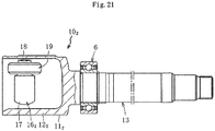
- the outer joint member 11 comprises the cup section 12 and the long stem section 13.
- the outer joint member 11 is manufactured by joining the cup member 12a and the shaft member 13a through butt welding, and manufacturing steps are described later in detail.
- the cup section 12 has a bottomed cylindrical shape that is opened at one end, and the inner peripheral surface 42 has the plurality of track grooves 30 that are formed equidistantly in a circumferential direction, thereby forming a partially cylindrical shape.
- the balls 41 (see FIG. 1 ) roll on the track grooves 30.
- the cup member 12a is an integrally-formed product being made of medium carbon steel, e.g., S53C, containing carbon of from 0.40 wt% to 0.60 wt%, and having a cylindrical portion 12a1 and a bottom portion 12a2.
- the cylindrical portion 12a1 has the track grooves 30 and the inner peripheral surface 42 described above.
- a boot mounting groove 32 is formed at an outer periphery of the cup member 12a on the opening side thereof, whereas a snap ring groove 33 is formed at an inner periphery.
- the bottom portion 12a2 has a shaft section having a solid shaft shape protruding toward the shaft member 13a side, that is, a short shaft section 12a3, and a joining end surface 50 ( FIG. 2c ) is formed at the short shaft section 12a3.
- the joining end surface 50 is finished by turning.
- a recessed portion 50b is formed on a radially inner side of the joining end surface 50, and as a result, the annular joining end surface 50 is formed on a radially outer side of the recessed portion 50b.
- the reference symbol D denotes an inner diameter of the joining end surface 50.
- the recessed portion 50b may be formed during forging, or may be formed by cutting. When the recessed portion 50b is formed during forging, the number of steps can be reduced. Further, the joining end surface 50 is formed into an annular shape, and hence time required for turning can be reduced.
- the long stem section 13 is a solid shaft that extends from the bottom portion 12a2 of the cup section 12 in the axial direction.
- a bearing mounting surface 14 and a snap ring groove 15 are formed at an outer periphery of the long stem section 13 on the cup member 12a side, whereas a spline shaft Sp serving as a torque transmission coupling portion is formed at an end portion on a side opposite to the cup section 12.
- the shaft member 13a is made of medium carbon steel, e. g. , S40C, containing carbon of from 0.30 wt% to 0. 55 wt%.
- a joining end surface 51 ( FIG. 2c ) is formed at an end portion on the cup member 12a side.
- the joining end surface 51 has a recess 52 formed in an inner diameter side.
- the reference symbol E denotes an inner diameter of the joining end surface 51.
- FIG. 2a to FIG. 2c and FIG. 5a to FIG. 5c are illustrations of an example in which the recess 52 is formed during forging and in which the inner diameter portion 53 is formed in the joining end surface 51 by cutting.
- the inner diameter portion 53 may be an inner diameter portion of the joining end surface 51, or may be an inner diameter portion of the recess 52.
- the recess 52 may maintain a forged surface. In that case, the inner diameter portion 53 that can be clearly distinguished from the recess 52 does not appear as illustrated.
- the recess 52 has a shallow bottom, that is, is very shallow with respect to an outer diameter of the joining end surface 51.
- a lower limit is approximately 1 mm. That is intended to secure a straight portion having a length in the axial direction necessary to perform ultrasonic flaw detection for defectiveness in dimension in the radial direction (penetration depth) of the welded portion 49.
- the above-mentioned lower limit is a value in view of the ultrasonic flaw detection. In view of reducing the pre-heating time through reduction of a volume near the joining portion, a corresponding depth of the recess 52 is desired.
- an upper limit of the depth of the recess 52 is approximately a limit value formed through forging (reference) ⁇ 1.5 mm. Excessively deep recess 52 may cause increase in forging load, degradation of die lifetime, and increase in processing cost. Even in the case of forming through cutting, excessively deep recess 52 may cause longer processing time and poor material yield.
- the inner diameter portion 53 of the joining end surface 51 while being dependent on the outer diameter of the shaft member 13a, is presupposed to secure a radial width of the welded portion 49 to be formed on the outer diameter side of the recess 52.
- the term "diameter" of the inner diameter is generally associated with a circular shape.
- a contour of the recess 52 as viewed from a plane perpendicular to the axial line of the shaft member 13a is not limited to have a circular shape, and the shape may be, for example, a polygon or an irregular shape.
- the welded portion 49 comprises metal that is molten and solidified during welding, that is, a molten metal and a heat-affected portion in a periphery of the molten metal.
- outer diameters B of the joining end surfaces 50 and 51 are set to equal dimensions for each joint size.
- the outer diameter B of the joining end surface 50 of the cup member 12a and the outer diameter B of the joining end surface 51 of the shaft member 13a need not be set to equal dimensions.
- a dimensional difference may be given as appropriate in such a manner that the outer diameter B of the joining end surface 51 is set slightly smaller than the outer diameter B of the joining end surface 50 or the like.
- the dimensional relationship between the outer diameter B of the joining end surface 50 and the outer diameter B of the joining end surface 51 is the same throughout the Description.
- the welded portion 49 is formed on the cup member 12a side with respect to the bearing mounting surface 14 of the shaft member 13a, and hence the bearing mounting surface 14 and the like can be processed in advance before welding so that post-processing after welding can be omitted. Further, in the electron beam welding, burrs are not generated at the welded portion. Thus, also on this point, post-processing for the welded portion can also be omitted, which can reduce manufacturing cost. Still further, total inspection on the welded portion through ultrasonic flaw detection can be performed.
- an inner diameter D of the joining end surface 50 of the cup member 12a is set smaller than an inner diameter E of the joining end surface 51 of the shaft member 13a.
- the recessed portion 50b has a smaller diameter than the recess 52.
- the joining end surface 50 of the cup member 12a partially protrudes to a radially inner side with respect to the joining end surface 51 having the inner diameter E.
- This protruding portion is referred to as a protruding surface 50a.
- the joining end surfaces 50 and 51 having such a shape are brought into abutment against each other, and the cup member 12a and the shaft member 13a are joined by welding.
- the protruding surface 50a is formed to be the same for each joint size.
- the cup member 12a is manufactured through manufacturing steps comprising a bar material cutting step S1c, a forging step S2c, an ironing step S3c, and a turning step S4c.
- the shaft member 13a is manufactured through manufacturing steps comprising a bar material cutting step S1s, a turning step S2s, and a spline processing step S3s.
- Intermediate components of the cup member 12a and the shaft member 13a thus manufactured are each assigned with a product number for management.
- the cup member 12a and the shaft member 13a are subjected to a welding step S6, an ultrasonic flaw detection step S6k, a heat treatment step S7, and a grinding step S8 so that the outer joint member 11 is completed.
- a bar material is cut into a predetermined length in accordance with a forging weight, thereby producing a billet.
- the billet is subjected to forging so as to integrally form the cylindrical portion, the bottom portion, and the projecting portion as a preform of the cup member 12a.
- Ironing is performed on the track grooves 30 and the cylindrical surface 42 of the preform, thereby finishing the inner periphery of the cylindrical portion of the cup member 12a.
- the outer peripheral surface, the boot mounting groove 32, the snap ring groove 33 and the like, and the joining end surface 50 are formed by turning.
- the cup member 12a in the form of an intermediate component is assigned with a product number for management.
- a bar material is cut into a predetermined length in accordance with an entire length of the shaft section, thereby producing a billet. After that, the billet is forged into a rough shape by upset forging depending on the shape of the shaft member 13a.
- the outer peripheral surface of the billet (bearing mounting surface 14, snap ring groove 15, minor diameter of the spline, end surface, and the like) and the joining end surface 51 of the billet at the end portion on the cup member 12a side are formed by turning.
- the spline shaft is formed by processing splines in the shaft member through rolling after turning. Note that, the method of processing the spline is not limited to the rolling, and press working or the like may be adopted instead as appropriate. After the spline processing, the shaft member 13a in the form of an intermediate component is assigned with a product number for management.
- the joining end surface 50 of the cup member 12a and the joining end surface 51 of the shaft member 13a are brought into abutment against and welded to each other.
- the welded portion 49 between the cup member 12a and the shaft member 13a is inspected by ultrasonic flaw detection.
- High frequency quenching and tempering are performed as heat treatment on at least the track grooves 30 and the inner peripheral surface 42 of the cup section 12 after welding and a necessary range of the outer periphery of the shaft member 13 after welding. Heat treatment is not performed on the welded portion 49.
- a hardened layer having a hardness of approximately from 58 HRC to 62 HRC is formed on each of the track grooves 30 and the inner peripheral surface 42 of the cup section 12. Further, a hardened layer having a hardness of approximately from 50 HRC to 62 HRC is formed in a predetermined range of the outer periphery of the shaft section 13.
- the heat treatment step is provided after the welding step, and hence the manufacturing steps are suited to a cup member and a shaft member having such shapes and specifications that the hardness of the heat-treated portion may be affected by temperature rise at the periphery due to heat generated during the welding.
- FIG. 4a is an illustration of a state after ironing of the cup member 12a.
- FIG. 4b is an illustration of a state after turning.
- a preform 12a' for the cup member 12a there are integrally formed a cylindrical portion 12a1', a bottom portion 12a2', and a short shaft section 12a3' in the forging step S2c.
- the track grooves 30 and the cylindrical surface 42 are formed by ironing in the ironing step S3c so that the inner periphery of the cylindrical portion 12a1' is finished as illustrated in FIG. 4a .
- the outer peripheral surface, the boot mounting groove 32, the snap ring groove 33, and the like of the cup member 12a as well as the joining end surface 50 of the short shaft section 12a3 and the outer diameter B and the inner diameter D of the joining end surface 50 are formed by turning as illustrated in FIG. 4b .
- FIG. 5a and FIG. 5b are illustrations of states of the shaft member 13a in the respective processing steps. That is, FIG. 5a is an illustration of a billet 13a" obtained by cutting a bar material. FIG. 5b is an illustration of a preform 13a' obtained by forging the billet 13a" into a rough shape by upset forging. FIG. 5c is an illustration of the shaft member 13a after turning and spline processing.
- the billet 13a" illustrated in FIG. 5a is formed in the bar material cutting step S1s.
- the preform 13a' is formed by increasing, if necessary, the shaft diameter of the billet 13a" in a predetermined range and forming a recess 52 at a joining-side end portion (end portion on the cup member 12a side) by upset forging as illustrated in FIG. 5b .
- FIG. 5c is an illustration of an example of forming the recess 52 during forging and forming the inner diameter portion 53 in the opening end portion by turning.
- the recess 52 may maintain a forged surface. In that case, the recess 52 and the inner diameter portion 53 are integrally formed, and hence may not be clearly distinguished from each other.
- the outer diameter of the shaft member 13a, the bearing mounting surface 14, the snap ring groove 15, an inner diameter portion 53 (inner diameter E), the joining end surface 51, and the outer diameter B thereof are formed by turning, as illustrated in FIG. 5c .
- the spline shaft Sp is processed at the end portion on the opposite side to the recess 52 by rolling or press forming.
- the outer diameter B of the joining end surface 50 of the cup member 12a illustrated in FIG. 4b is set to an equal dimension for one joint size.
- the outer diameter B of the joining end surface 51 located at the end portion on the cup member 12a side is set to an equal dimension to the outer diameter B of the joining end surface 50 of the cup member 12a irrespective of the shaft diameter and the outer peripheral shape.
- the joining end surface 51 of the shaft member 13a is located at the position on the cup member 12a side with respect to the bearing mounting surface 14.
- the outer joint member 11 compatible with various vehicle types can be manufactured in such a manner that, while the cup member 12a is prepared for common use, only the shaft member 13a is manufactured to have a variety of shaft diameters, lengths, and outer peripheral shapes depending on vehicle types, and both the members 12a and 13a are welded to each other. Details of the preparation of the cup member 12a for common use are described later.
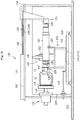
- FIG. 6 is a schematic elevation view of a welding apparatus for illustrating a state before welding
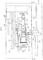
- FIG. 7 is a schematic plan view of the welding apparatus for illustrating a state during welding.
- a welding apparatus 100 mainly comprises an electron gun 101, a rotation device 102, a chuck 103, a center 104, a tailstock 105, workpiece supports 106, a center 107, a case 108, and a vacuum pump 109.
- the cup member 12a and the shaft member 13a being workpieces are placed on the workpiece supports 106 arranged inside the welding apparatus 100.
- the chuck 103 and the centering jig 107 arranged at one end of the welding apparatus 100 are coupled to the rotation device 102.
- the chuck 103 grips the cup member 12a to rotate the cup member 12a by the rotation device 102 under a state in which the center 107 has centered the cup member 12a.
- the center 104 is integrally mounted to the tailstock 105 arranged at another end of the welding apparatus 100. Both the center 104 and the tailstock 105 are configured to reciprocate in the axial direction (lateral direction of FIG. 6 ).
- a center hole of the shaft member 13a is set on the center 104 so that the shaft member 13a is centered.
- the vacuum pump 109 is connected to the case 108 of the welding apparatus 100.
- a "sealed space” herein refers to a space 111 defined by the case 108.
- the cup member 12a and the shaft member 13a are entirely received in the sealed space 111.
- the electron gun 101 is arranged at a position corresponding to the joining end surfaces 50 and 51 of the cup member 12a and the shaft member 13a.
- the electron gun 101 is configured to be approachable to and separable from the workpieces.
- the cup member 12a and the shaft member 13a being workpieces are stocked at a place different from the place of the welding apparatus 100.
- the respective workpieces are taken out by, for example, a robot, are conveyed into the case 108 of the welding apparatus 100 opened to the air as illustrated in FIG. 6 , and are set at predetermined positions of the workpiece supports 106.
- the center 104 and the tailstock 105 are retreated to the right side of FIG. 6 , and hence a gap is formed between the joining end surfaces 50 and 51 of the cup member 12a and the shaft member 13a.
- the center 104 and the tailstock 105 are advanced to the left side as illustrated in FIG. 7 to eliminate the gap between the joining end surfaces 50 and 51 of the cup member 12a and the shaft member 13a.
- the cup member 12a is centered by the center 107 and fixed by the chuck 103, whereas the shaft member 13a is centered and supported by the center 104.
- the workpiece supports 106 are moved away from the workpieces (12a and 13a).
- the distance between the workpiece supports 106 and the workpieces (12a and 13a) may be infinitesimal, and hence illustration of this distance is omitted from FIG. 7 .
- the welding apparatus 100 may have such a structure that the workpiece supports 106 are retreated downward greatly.
- the electron gun 101 is then caused to approach the workpieces (12a and 13a) up to a predetermined position, and the workpieces (12a and 13a) are rotated to start pre-heating.
- the temperature is set lower than the welding temperature by, for example, radiating an electron beam under a state in which the electron beam is larger than the beam size during welding.
- the cooling rate after welding is reduced by pre-heating, thereby being capable of preventing a quenching crack.
- the electron gun 101 When a predetermined pre-heating time has elapsed, the electron gun 101 is retreated to a predetermined position, and radiates the electron beam from the outer side of the workpieces (12a and 13a) in the radial direction to start welding. When the welding is finished, the electron gun 101 is retreated, and the rotation of the workpieces (12a and 13a) is stopped.
- the sealed space 111 is then opened to the air. Then, the center 104 and the tailstock 105 are retreated to the right side in the drawing sheet and the chuck 103 is opened under a state in which the workpiece supports 106 are raised to support the workpieces. After that, for example, the robot grips the workpieces (12a and 13a), takes the workpieces out of the welding apparatus 100, and places the workpieces into alignment on a cooling stocker. In this embodiment, the cup member 12a and the shaft member 13a are entirely received in the sealed space 111, and hence the configuration of the sealed space 111 defined in the case 108 can be simplified.
- the cup member 12a having a carbon content of from 0.4% to 0.6% and the shaft member 13a having a carbon content of 0.3% to 0.55% were used and welded to each other in the welding apparatus 100 under the condition that the pressure in the sealed space 111 defined in the case 108 was set to 6.7 Pa or less.
- a periphery including the joining end surfaces 50 and 51 of the cup member 12a and the shaft member 13a were soaked by pre-heating with the electron beam to have a temperature of from 300°C to 650°C, and then electron beam welding was performed.
- the pre-heating time was able to be reduced to approximately one-half or less as compared to the case where the recess is not formed in the inner diameter side of the joining end surface, and a favorable welded portion satisfying the required strength was able to be obtained.
- a ventilation hole communicating with an inside of the cup member 12a and with the recess 52 may be formed, and the space inside the cup member 12a may be drawn to vacuum to the pressure of 1.3 Pa, and thereafter the joining surfaces may be brought into abutment against each other for welding.
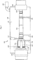
- FIG. 8 and FIG. 9 are a front view and a plan view, respectively, of an ultrasonic flaw-detection apparatus having a welded outer joint member mounted thereto.
- FIG. 8 corresponds to an illustration as viewed from the direction of the arrow VIII-VIII of FIG. 9 .
- FIG. 10 and FIG. 11 are a front view and a plan view, respectively, of the ultrasonic flaw-detection apparatus during the ultrasonic flaw detection.
- FIG. 10 corresponds to an illustration as viewed from the direction of the arrow X-X of FIG. 11 .
- an ultrasonic flaw-detection apparatus 120 mainly comprises a base 121, a water bath 122, a workpiece support 123, a workpiece holding member 124, a rotary drive device 125, a pressing device 135, and a drive positioning device 136 (see FIG. 9 ).
- the water bath 122 is mounted at the center of the base 121.
- the rotary drive device 125 is configured to rotate an intermediate product 11' (hereinafter also referred to as "workpiece 11'") of the outer joint member 11.
- the pressing device 135 is configured to press an axial end of the workpiece 11'.
- the drive positioning device 136 is configured to drive and position a probe.
- the workpiece support 123 comprises support rollers 126 and 127 configured to allow the workpiece 11' to be placed thereon in a freely rotatable manner.
- the support rollers 126 are arranged at a position close to the welded portion.
- the support rollers 127 are arranged near a center portion of the shaft section 13.
- the support rollers 126 and 127 are constructed by pairs of rollers provided on both sides in the axial line of the shaft section 13 so that the shaft section 13 of the workpiece 11' can be stably supported.
- the support rollers 126 and 127 are capable of adjusting the placement position of the workpiece 11' in the axial direction (lateral direction of FIG. 8 ) and the radial direction (vertical direction of FIG. 8 ) in consideration of a joint size, dimensions, and weight balance of the workpiece 11'.
- the workpiece holding member 124 is mounted to the workpiece support 123 at a position displaced in a plane of FIG. 9 from an axial line of the workpiece 11'.
- the workpiece holding member 124 comprises a lever 128, and a workpiece holding roller 129 is arranged at an end portion of the lever 128.
- the lever 128 is pivotable in the plane of FIG. 9 , and is movable in the vertical direction of FIG. 8 .
- the workpiece support 123 is mounted to a support 134 through intermediation of a linear-motion bearing 130 comprising rails 131 and linear guides 132, and is movable in the axial direction (lateral direction of FIG. 8 and FIG. 9 ).
- the support 134 is mounted to the base 121.
- the workpiece support 123 can be driven to be positioned at a desired position by an actuator (not shown) arranged on an outside of the water bath 122 through intermediation of a rod 133 coupled to an end portion (left end portion of FIG. 8 and FIG. 9 ).
- the rotary drive device 125 comprises a rotary shaft 143 having a rotary disc 144 mounted thereto, and this rotary shaft 143 is driven to rotate by a motor (not shown) arranged on the outside of the water bath 122.
- a mounting base 137 is arranged on an upper side of the ultrasonic flaw-detection apparatus 120.
- a base plate 145 for the pressing device 135 is mounted to the mounting base 137 through intermediation of a linear-motion bearing 138 comprising a rail 139 and a linear guide 140 so that the base plate 145 of the pressing device 135 is movable in the axial direction (lateral direction of FIG. 8 and FIG. 9 ).
- a rod 142 of a pneumatic cylinder 141 is coupled to an end portion of the base plate 145 so that the base plate 145 is driven, that is, axially moved by the pneumatic cylinder 141.
- the pressing device 135 is held in abutment against the axial end of the shaft section 13 of the workpiece 11' through a free bearing 146.
- the drive device 136 for a probe is arranged at a position displaced in the axial line of the workpiece 11'.
- This drive device 136 comprises actuators for the X-axis direction and the Y-axis direction so that a probe 147 is driven to be positioned in the X-axis direction and the Y-axis direction.
- An actuator 148 for the X-axis direction and an actuator 149 for the Y-axis direction are each an electric ball-screw type (ROBO cylinder), which is capable of performing positioning with high accuracy.
- the reference symbol 150 denotes a rail for a linear-motion bearing.
- the drive device 136 is arranged on the outside of the water bath 122, and the probe 147 and a holder 151 therefor are arranged in the water bath 122.
- the workpiece 11' after welding is placed on the workpiece support 123 by a loader (not shown) (see FIG. 8 and FIG. 9 ).
- the workpiece support 123 is located at an appropriate interval from the rotary drive device 125 in the axial direction of the workpiece 11', and the workpiece holding member 124 raises and pivots the lever 128 thereof so as to be substantially parallel to the axial line of the workpiece 11'.
- the pressing device 135 and the drive device 136 for a probe wait at retreated positions.
- the lever 128 of the workpiece holding member 124 is pivoted so as to be substantially perpendicular to the axial line of the workpiece 11', and then lowered to hold the workpiece 11' from above (see FIG. 10 ). Then, water is supplied to the water bath 122.
- the ultrasonic flaw-detection apparatus 120 has the configuration of performing flaw detection under water, and hence ultrasonic waves are satisfactorily propagated. Thus, inspection can be performed with high accuracy.
- the pneumatic cylinder 141 is driven to cause the pressing device 135 to be advanced and pressed against the axial end of the workpiece 11', thereby pressing the opening rim of the cup section 12 of the workpiece 11' against the rotary disc 144 of the rotary drive device 125.
- the workpiece support 123 is also moved toward the rotary drive device 125.
- the workpiece 11' is positioned in the axial direction and the radial direction.
- the motor (not shown) of the rotary drive device 125 is activated, thereby rotating the workpiece 11'.
- the drive device 136 is moved in the X-axis direction, and then moved in the Y-axis direction, thereby positioning the probe 147 at a flaw detection position.
- the probe 147 in this state is indicated by the broken line in FIG. 10 .
- the ultrasonic flaw detection is performed. After the completion of the ultrasonic flaw detection, water is drained from the water bath 122, and the workpiece 11' is delivered from the ultrasonic flaw-detection apparatus 120 by the loader (not shown). In such a manner, the ultrasonic flaw detection is sequentially repeated on the workpiece 11'.
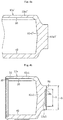
- FIG. 12a is an illustration of a non-defective welded product.
- FIG. 12b is an illustration of a defective welded product.
- FIG. 13 is a view for illustrating findings in the course of development.
- the probe 147 is positioned at a flaw detection position away from the welded portion 49 by a predetermined distance.
- the flaw detection position is preset for each joint size.
- a transmission pulse G from the probe 147 is caused to obliquely enter from a surface of the workpiece 11'.
- a reflected echo having been received is displayed as waveforms, and the waveforms may be observed to determine a presence or absence of defectiveness (angle beam flaw detection method).
- the reference symbol ⁇ 1 denotes an incident angle
- the reference symbol ⁇ 2 denotes a refraction angle. In the case of the embodiment, the incident angle ⁇ 1 is about 20°, and the refraction angle ⁇ 2 is about 45°.
- a presence or absence of the penetration defectiveness is mainly detected through detection of a position of a back bead. That is, workpieces having a penetration depth equal to or larger than a determination reference Wmin to reach a radially inner side are determined as non-defective welded products, and workpieces having a penetration depth smaller than the determination reference Wmin to terminate on a radially outer side are determined as defective welded products.
- the inner diameter portion 53 of the recess 52 formed in the joining end surface 51 is matched with the determination reference Wmin.
- the reference symbol E denotes an inner diameter of (the inner diameter portion 53 of) the recess 52, and also denotes an inner diameter of the joining end surface 51.
- the reference symbol Wa denotes a target penetration depth.
- the welded portion 49 is formed on the radially outer side of the recess 52.
- a closed cavity is formed on the radially inner side of the welded portion 49.
- a back bead 491 cannot be visually confirmed from outside.
- the workpiece 11' is driven by the rotary drive device 125 to rotate.
- the probe 147 positioned at the flaw detection position away from the welded portion 49 by the predetermined distance collects data of the entire periphery of the workpiece 11'.
- data of a single rotation (360°) of the workpiece 11' is collected.
- the probe 147 is sequentially shifted in the axial direction at a minute pitch (for example, 0.5 mm) to collect data of a plurality of rotations (for example, five rotations). Based on those pieces of data, non-defective/defective determination is made.
- a threshold of a reflected echo to be used in the non-defective/defective determination is determined based on a welding pattern corresponding to the determination reference Wmin.
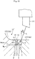
- the protruding surface 50a which protrudes toward the radially inner side with respect to the inner diameter E of the joining end surface 51 of the shaft member 13a.
- the reflected echo R has a large echo height exceeding the threshold of the reflected echo for the non-defective/defective determination. Thus, determination that the welded product is defective is made. For this reason, it was proved that the determination as to whether the welded product was non-defective or defective was difficult.
- a measure is taken by forming the protruding surface 50a, which protrudes toward the radially inner side with respect to the inner diameter E of the joining end surface 51 of the shaft member 13a, in the joining end surface 50 of the cup member 12a.
- the non-defective welded product has sufficient penetration.
- the transmission pulse G from the probe 147 enters the cup section 12 through the back bead 491 having reached the radially inner side beyond the determination reference Wmin, and travels straight as it is.
- the transmission pulse G travels to the cup section 12 side by being reflected due to the inner diameter D of the cup section 12. Therefore, the probe 147 does not receive a reflected echo. That is, even when the transmission pulse G enters the back bead 491, the boundary surface of the back bead 491, which is perpendicular to the transmission pulse G, does not exist. Therefore, although a slightly-scattered reflected echo is generated, the reflected echo which may cause the detection error is not generated.
- the echo height of the reflected echo received by the probe 147 is equal to or less than the threshold, and hence determination that the welded product is non-defective is made.
- the echo height of the reflected echo becomes lower.
- the accuracy in the inspection can be enhanced.
- the transmission pulse G is reflected by the joining end surface 51 and a chamfered portion 51a, and the scattered reflected echo R is received by the probe 147.
- the reflected echo R exceeds the threshold of the reflected echo for the non-defective/defective determination, and hence determination that the welded product is defective is made.
- the protruding surface 50a is formed on the joining end surface 50, and hence the echo heights of the reflected echoes can be clearly discriminated from each other. Thus, the determination as to whether the welded product is non-defective or defective can be made with high accuracy.
- Q is a height of the back bead 491 from the inner diameter E of the joining end surface 51 as illustrated in FIG. 12a .
- the dimensions of the protruding surface 50a may be set as appropriate.
- the inner diameter E of the joining end surface 51 is also an inner diameter (of the inner diameter portion 53) of the recess 52.
- the operation of loading the workpiece 11', the supply and drainage of water, the ultrasonic flaw detection, and the operation of unloading the workpiece can be performed in conjunction with each other, and the ultrasonic flaw detection can be automated.
- accuracy, operability, and efficiency in the inspection can be enhanced, which is suited to the inspection on the welded portion of the outer joint member of the constant velocity universal joint being a mass-produced product.
- flaw detection is performed under water, and hence ultrasonic waves are satisfactorily propagated.
- inspection can be performed with much higher accuracy.
- the shape of the welded portion in which the protruding surface 50a is formed on the joining end surface 50, the echo heights of the reflected echoes can clearly be discriminatedfrom each other.
- the determination as to whether the welded product is non-defective or defective can be made with high accuracy.
- a shaft member 13b illustrated in FIG. 14 and FIG. 15 is used as a general stem type on the inboard side.
- the shaft member 13b has the joining end surface 51 to be brought into abutment against the joining end surface 50 (see FIG. 4b ) of the bottom portion 12a2 (short shaft section 12a3) of the cup member 12a.
- the outer diameter B and the inner diameter E of the joining end surface 51 are set to the equal dimensions to the outer diameter B and the inner diameter E of the joining end surface 51 of the shaft member 13a of the long stem type illustrated in FIG. 5c .
- the inner diameter D of the joining end surface 50 of the cup member 12a is set smaller than the inner diameter E of the joining end surface 51 of the shaft member 13b.
- the protruding surface 50a protruding to the radially inner side with respect to the inner diameter E of the joining end surface 51 of the shaft member 13b is formed.
- the joining end surfaces 50 and 51 having such shape are brought into abutment against each other to be welded so that the cup member 12a and the shaft member 13b are joined to each other.
- the shaft member 13b is used as the general stem type on the inboard side. Accordingly, the shaft member 13b comprises a shaft section with a small length, and a sliding bearing surface 25 formed on an axial center portion thereof, and a plurality of oil grooves 26 are formed in the sliding bearing surface 25.
- the spline shaft Sp and the snap ring groove 48 are formed in an end portion on the side opposite to the cup member 12a side.
- the outer diameter B of the joining end surface 51 of the shaft member 13a or 13b is set to an equal dimension.
- the outer diameter B of the joining end surface 50 of the cup member 12a and the joining end surface 51 of the shaft member 13a or 13b is set to an equal dimension for each joint size.
- the cup member prepared for common use for each joint size, and the shaft member having a variety of specifications of the shaft section for each vehicle type can be prepared in a state before heat treatment.
- the intermediate component of each of the cup member 12a and the shaft member 13a or 13b can be assigned with a product number for management. Even when standardizing product types of the cup member 12a, various types of the outer joint members 11 satisfying requirements can be produced quickly through combination of the cup member 12a and the shaft member 13a or 13b having a variety of specifications of the shaft section for each vehicle type. Therefore, standardization of a product type of the cup member 12a can reduce cost and alleviate a burden of production management.
- the standardization of the product type of the cup member is described above by taking the differences in types, such as the general length stem type and the long stem type, as an example for easy understanding, but the present invention is not limited thereto.
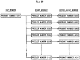
- FIG. 16 An example of standardization of a product type of the cup member is illustrated in FIG. 16 .
- the cup member is prepared for common use for one joint size, and is assigned with, for example, a product number C001 for management.
- the shaft member has a variety of specifications of the shaft section for each vehicle type, and is assigned with, for example, a product number S001, S002, or S(n) for management. For example, when the cup member assigned with the product number C001 and the shaft member assigned with the product number S001 are combined and welded to each other, the outer joint member assigned with a product number A001 can be produced.
- the cup member is not limited to one type for one joint size, that is, not limited to one type assigned with a single product number.
- the cup member comprises cup members of a plurality of types (assigned with a plurality of product numbers, respectively) that are prepared for one joint size based on different specifications of a maximum operating angle, and are each prepared so that the outer diameter B of the joining end surface of each of those cup members has an equal dimension.
- FIG. 17a is a partial sectional front view of the outer joint member.
- FIG. 17b is an enlarged view of a portion "b" of FIG. 17a.
- FIG. 17c is a view for illustrating a state before welding in FIG. 17b .
- FIG. 18 is a vertical sectional view for illustrating the cup member before welding.
- a form of a protruding surface formed on a joining end surface of the cup member of this second embodiment is different from that in the first embodiment described above.
- Other configurations are the same as those in the first embodiment.
- parts that have the same function as those of the first embodiment are denoted by the same reference symbols except for the subscripts, and overlapping description is omitted.
- the shaft member 13a side is also not different from that of the first embodiment ( FIG. 2a to FIG. 2c ). That is, as illustrated in FIG. 17a to FIG. 17c , the recess (52: see FIG. 2a to FIG. 2c ) is formed on the end surface of the shaft member 13a, and the joining end surface 51 is formed into an annular surface having the inner diameter E.
- a joining end surface 50 1 formed on a short shaft section 12a3 1 of a cup member 12a 1 is annular, and a projecting portion 50b i is formed on the radially inner side.
- a diameter D 1 of the annular joining end surface 50 1 on the radially inner side corresponds to the inner diameter D of the joining end surface 50 of the cup member 12a of the first embodiment of the outer joint member.
- a portion of the joining end surface 50 1 on the radially inner side protrudes toward the radially inner side with respect to the inner diameter E of the joining end surface 51 of the shaft member 13a. This protruding portion is referred to as a protruding surface 50a 1 as in the first embodiment.
- the cup member 12a 1 can be formed by turning an end surface of the short shaft section 12a3' of the preform 12a' ( FIG. 4a ) for the cup member of the first embodiment after ironing at only a portion of the joining end surface 50 1 on the radially outer side.
- the time for the turning can be reduced, with good material yield.
- the projecting portion 50b 1 on the radially inner side can also be subjected to turning.
- the number of steps can be reduced by maintaining the forged surface as it is.
- a height of the protruding portion 50b 1 is set smaller than a depth of the recess 52 (see FIG. 2a to FIG. 2c ) so as to prevent interference with the abutment of the joining end surfaces 50 1 and 51.
- the cup member 12a or 12a 1 is not limited to one type for one joint size, that is, not limited to one type assigned with a single product number.
- the cup member encompasses cup members of a plurality of types (assigned with a plurality of product numbers, respectively) that are prepared for one joint size based on different specifications of a maximum operating angle, and are also prepared so that the outer diameters of the above-mentioned joining end surfaces of the cup members are set to equal dimensions and that the protruding surfaces are formed into the same shape.
- the cup member encompasses, for example, cup members of a plurality of types (assigned with a plurality of product numbers, respectively) that are prepared for one joint size in order to achieve management of the cup members in a plurality of forms including intermediate components before heat treatment and finished components subjected to heat treatment in consideration of the joint function, the circumstances at the manufacturing site, the productivity, and the like, and are also prepared so that the outer diameters of the above-mentioned joining end surfaces of the cup members are set to equal dimensions and that the protruding surfaces are formed into the same shape.
- setting the outer diameter B of the joining end surface 50 or 50 1 of the cup member 12a or 12a 1 to an equal dimension for each joint size, or forming the protruding surface 50a or 50a 1 into the same shape for each joint size may be applied also to different types of constant velocity universal joints.
- setting outer diameters of the joining end surfaces of a tripod type constant velocity universal joint and a double-offset constant velocity universal joint to equal dimensions, and forming the protruding surfaces into the same shape on the inboard side are also encompassed.
- setting outer diameters of the joining end surfaces of a Rzeppa type constant velocity universal joint and an undercut-free constant velocity universal joint to equal dimensions, and forming the protruding surfaces into the same shape on the outboard side are also encompassed.
- setting the outer diameters of the joining end surfaces of the constant velocity universal joints on the inboard side and the outboard side to equal dimensions, and forming the protruding surfaces into the same shape on the inboard side and the outboard side are also possible.
- At least one of the cup member 12a or 12a 1 and the shaft member 13a or 13b before welding may be prepared as an intermediate component without performing heat treatment.
- heat treatment and finishing such as grinding and quenched-steel cutting work are preformed after welding.
- this configuration is suited to the cup members 12a and 12a 1 and the shaft members 13a and 13b having such shapes and specifications that the hardness of the heat-treated portion may be affected by temperature rise at the periphery due to heat generated during welding after heat treatment.
- the intermediate component is assigned with a product number for management.
- At least one of the cup member 12a or 12a 1 and the shaft member 13a or 13b before welding may be prepared as a finished component subjected to heat treatment.
- the finished component subjected to heat treatment is a finished component subjected to the heat treatment and the finishing such as grinding after the heat treatment or quenched-steel cutting work.
- the cup members and the shaft members are each assigned with a product number for management. Therefore, the cost is significantly reduced through the standardization of a product type of the cup members 12a and 12a 1 , and the burden of production management is significantly alleviated.
- cup members 12a and 12a 1 prepared for common use and the shaft members 13a and 13b having a variety of specifications of the shaft section can be manufactured separately until the cup members and the shaft members are formed into the finished components subjected to the finishing such as forging, turning, heat treatment, grinding, and quenched-steel cutting work. Further, as well as reduction of setups and the like, the enhancement of productivity is achieved.
- the cup members 12a and 12a 1 and the shaft members 13a and 13b as the finished components are not limited to members subjected to finishing such as the grinding after the heat treatment or the quenched-steel cutting work as described above.
- the cup members 12a and 12a 1 and the shaft members 13a and 13b assuming a state after completion of heat treatment and before being subjected to the finishing are encompassed.
- FIG. 19 is an illustration of a second embodiment of a manufacturing method of the outer joint member.
- the heat treatment step for the cup member which is involved in the heat treatment step S7 in FIG. 3 , is provided before the welding step S6 and named "heat treatment step S5c", to thereby prepare the cup member as a finished product.
- the matters described above in relation to the first embodiment of the manufacturing method that is, the overview of the respective steps, the states of the cup member and the shaft member in the main processing steps, the preparation of the cup member for common use, the welding method, the ultrasonic flaw detection, the standardization of the product type, the configuration of the outer joint member, and the like are also applicable to the second embodiment.
- the cup member 12a has a shape extending from the joining end surface 50 to the large-diameter cylindrical portion 12a1 via the bottomportion 12a2, and the portions to be subjected to heat treatment that involves quenching and tempering are the track grooves 30 and the cylindrical inner peripheral surface 42 located at the inner periphery of the cylindrical portion 12a1. Therefore, the cup member 12a generally has no risk of thermal effect on the heat-treated portion during the welding. For this reason, the cup member 12a is subjected to heat treatment before the welding to be prepared as a finished product. Such manufacturing steps are suitable in practical use.
- the cup member 12a is subjected to heat treatment for preparing the cup member 12a as a finished product, and is therefore assigned with a product number indicating a finished product for management.
- the standardization of the product type of the cup member 12a remarkably reduces the cost and alleviates the burden of production management.
- the cup member 12a can be manufactured solely until the cupmember 12a is completed as a finished product through the forging, turning, and heat treatment.
- the productivity is enhanced by virtue of reduction of setups and the like as well.
- FIG. 16 for illustrating the example of standardization of the product type of the cup member described above in relation to the first embodiment of the manufacturingmethod, only the product number of the cup member in FIG. 16 is changed to the product number indicating a finished product, whereas the product numbers of the shaft member and the outer joint member are the same as those of the first embodiment of the manufacturing method. Therefore, description thereof is omitted herein.
- FIG. 20 is an illustration of a third embodiment of a manufacturing method of the outer joint member.
- the heat treatment steps for the cup section and the shaft section which are involved in the heat treatment step S7 in FIG. 3 described above in relation to the first embodiment, and the grinding step S8 for the shaft section in FIG. 3 are provided before the welding step S6 in the sequence and named "heat treatment step S5c for cup member", “heat treatment step S4s for shaft member”, and "grinding step S5s".
- both the cup member and the shaft member are prepared as finished products.
- a hardened layer having a hardness of approximately from 50 HRC to 62 HRC is formed in a predetermined range of the outer peripheral surface of the shaft member by induction quenching in the heat treatment step S4s.
- Heat treatment is not performed on a predetermined portion in the axial direction, which includes the joining end surface 51.
- the heat treatment for the cup member, the assignment of the product number, and the like are the same as those of the second embodiment on the manufacturing method, and redundant description is therefore omitted herein.
- the shaft member is transferred to the grinding step S5s so that the bearing mounting surface 14 and the like are finished.
- the shaft member is obtained as a finished product.
- the shaft member is assigned with a product number indicating a finished product for management.
- the manufacturing steps of the third embodiment are suitable in a case of a cup member and a shaft member having shapes and specifications with no risk of thermal effect on the heat-treated portion during the welding.
- both the cup member and the shaft member can be assigned with product numbers indicating finished products for management.
- the standardization of the product type of the cup member further remarkably reduces the cost and alleviates the burden of production management.
- the cup member and the shaft member can be manufactured independently of each other until the cup member and the shaft member are completed as finished products through the forging, turning, heat treatment, grinding after heat treatment, and the like.
- the productivity is further enhanced by virtue of reduction of setups and the like as well.
- the product numbers of the cup member and the shaft member in FIG. 16 are changed to the product numbers indicating finished products.
- the outer joint member is the same as that of the first embodiment of the manufacturing method. Therefore, description thereof is omitted herein.
- the cup member and the shaft member to be prepared as finished products are not limited to the cup member and the shaft member subjected to finishing such as the above-mentioned grinding after heat treatment or cutting after quenching, and encompass a cup member and a shaft member in a state in which the heat treatment is completed while the finishing is uncompleted.
- the cup member is not limited to one type for one joint size, that is, not limited to one type assigned with a single product number.
- the cup member encompasses, for example, cup members of a plurality of types (assigned with a plurality of product numbers, respectively) that are prepared for one joint size based on different specifications of a maximum operating angle, and are also prepared so that the outer diameters B of the above-mentioned joining end surfaces of the cup members are set to equal dimensions.
- the cup member encompasses, for example, cup members of a plurality of types (assigned with a plurality of product numbers, respectively) that are prepared for one joint size in order to achieve management of the cup members in a plurality of forms including intermediate components before heat treatment and finished components in consideration of the joint function, the circumstances at the manufacturing site, the productivity, and the like, and are also prepared so that the outer diameters B of the above-mentioned joining end surfaces of the cup members are set to equal dimensions.
- a plunging type constant velocity universal joint 10 2 illustrated in FIG. 21 is a tripod type constant velocity universal joint (TJ), and comprises an outer joint member 11 2 , an inner joint member 16 2 , and rollers 19 serving as torque transmitting elements.
- the outer joint member 11 2 comprises a cup section 12 2 and the long stem section 13 that extends from a bottom of the cup section 12 2 in the axial direction.
- the inner joint member 16 2 comprises a tripod member 17 comprising three equiangular leg shafts 18 configured to support the rollers 19 in a freely rotatable manner, and is housed along an inner periphery of the cup section 12 2 of the outer joint member 11 2 .
- the rollers 19 are arranged between the outer joint member 11 2 and the inner joint member 16 2 , and configured to transmit torque therebetween.
- the inner ring of the support bearing 6 is fixed to the outer peripheral surface of the long stem section 13, and the outer ring of the support bearing 6 is fixed to the transmission case with the bracket (not shown) .
- the outer joint member 11 2 is supported by the support bearing 6 in a freely rotatable manner, and thus the vibration of the outer joint member 11 2 during driving or the like is prevented as much as possible.
- the outer joint member 11 2 comprises a cup section 12 2 and the long stem section 13.
- the cup section 12 2 has a bottomed cylindrical shape that is opened at one end, and has track grooves 30 2 , on which the rollers 19 are caused to roll, formed at three equiangular positions on an inner peripheral surface 31 2 .
- the long stem section 13 extends from the bottom of the cup section 12 2 in the axial direction and comprises the spline shaft Sp serving as the torque transmitting coupling portion formed at the outer periphery of the end portion on the side opposite to the cup section 12 2 .
- the outer joint member 11 2 is formed by welding the cup member 12a 2 serving as the cup section 12 2 and the shaft member 13a serving as the long stem section 13 to each other.
- the cup member 12a 2 is an integrally-formed product having a cylindrical portion 12a1 2 and a bottom portion 12a2 2 , and has track grooves 130 and an inner peripheral surface 131 formed at the inner periphery of the cylindrical portion 12a1 2 .
- a short shaft section 12a3 2 is formed at the bottom portion 12a2 2 .
- a boot mounting groove 32 is formed at an outer periphery of the cup member 12a 2 on the opening side.
- the bearing mounting surface 14 and the snap ring groove 15 are formed at the outer periphery on the cup member 12a 2 side, and the spline shaft Sp is formed at an end portion on the side opposite to the cup member 12a 2 .
- a joining end surface 50 2 formed at the short shaft section 12a3 2 of the bottom portion 12a 1 of the cup member 12a 2 and the joining end surface 51 formed at the end portion of the shaft member 13a on the cup member 12a 2 side are brought into abutment against each other, and are welded to each other by radiating an electron beam from the radially outer side.
- the welded portion 49 comprises metal that is molten and solidified during welding, that is, the molten metal, and the heat-affected portion in the periphery thereof.
- the outer diameters B of the joining end surface 50 2 and the joining end surface 51 are set to equal dimensions for each joint size.
- the welded portion 49 is formed on the cup member 12a 2 side with respect to the bearing mounting surface 14 of the shaft member 13a, and hence the bearing mounting surface 14 and the like can be processed in advance so that post-processing after welding can be omitted. Further, due to the electron beam welding, burrs are not generated at the welded portion. Thus, post-processing for the welded portion can also be omitted, which can reduce the manufacturing cost.
- the method of butt-welding comprises, with the cup member 12a, 12a 1 , or 12a 2 being a first workpiece and the shaft member 13a or 13b being a second workpiece, bringing a solid shaft-shaped end portion of the first workpiece 12a, 12a 1 , or 12a 2 and a solid shaft-shaped end portion of the second workpiece 13a or 13b into abutment against each other, and radiating a high energy intensity beam from a radially outer side to perform butt-welding.
- the second workpiece 13a or 13b has the recess 52 on the joining end surface 51, and the first workpiece 12a, 12a 1 , or 2a 2 has the joining end surface 50, 50 1 , or 50 2 protruding toward the radially inner side with respect to the inner diameter E of the joining end surface 51 of the second workpiece 13a or 13b.
- the joining end surface 50 or 50 2 of the first workpiece 12a or 12a 2 has the recessed portion 50b having a diameter smaller than a diameter of the recess 52. With this, the joining end surface 50 or 50 2 is formed into an annular surface, and hence time required for turning can be reduced.
- the joining end surface 50 1 of the first workpiece 12a 1 has, at a center portion thereof, the protruding portion 50b 1 which has a diameter smaller than a diameter of the recess 52 and which has a height smaller than a depth of the recess 52. Also in this case, the joining end surface 50 1 is formed into an annular surface.
- the recess 52 may be formed by cutting work, or may be formed during forging. As compared to the former, the latter is more advantageous in terms of reduction in number of steps and in terms of a material yield.
- the protruding surface 50a or 50a 1 of the joining end surface 50, 50 1 , or 50 2 may have the same shape for each joint size.
- workability for the cup members 12a, 12a 1 , and 12a 2 to be standardized in product type is enhanced. Therefore, the productivity can be further enhanced, and the burden of product management can be further reduced.
- the protruding surface 50a or 50a 1 is formed on the joining end surface 50, 50 1 , or 50 2 of the cup member 12a, 12a 1 , or 12a 2 .
- the protruding surface is formed on the radially inner side of the joining end surface of the cup member.
- the protruding surface may be formed on the radially inner side of the joining end surface of the shaft member.
- the ultrasonic flaw detection in this case may be performed by allowing the ultrasonic waves to enter from the surface side of the cup member.
- the present invention is applicable not only to the case of the electron beam welding but also to the case of employing laser welding or other welding through use of a high energy intensity beam.
- the double-offset type constant velocity universal joint and the tripod type constant velocity universal joint are exemplified as the plunging type constant velocity universal joint.
- the present invention is also applicable to an outer joint member of a cross-groove type constant velocity universal joint or other plunging type constant velocity universal joint, and to an outer joint member of a fixed type constant velocity universal joint.
- the case of applying the present invention to the outer joint member of the constant velocity universal joint constructing a drive shaft is described as an example.
- the present invention is also applicable to an outer joint member of a constant velocity universal joint constructing a propeller shaft.
Landscapes
- Engineering & Computer Science (AREA)
- Physics & Mathematics (AREA)
- Mechanical Engineering (AREA)
- General Engineering & Computer Science (AREA)
- Optics & Photonics (AREA)
- Biochemistry (AREA)
- Pathology (AREA)
- Analytical Chemistry (AREA)
- Life Sciences & Earth Sciences (AREA)
- General Health & Medical Sciences (AREA)
- General Physics & Mathematics (AREA)
- Immunology (AREA)
- Chemical & Material Sciences (AREA)
- Health & Medical Sciences (AREA)
- Plasma & Fusion (AREA)
- Acoustics & Sound (AREA)
- Welding Or Cutting Using Electron Beams (AREA)
- Laser Beam Processing (AREA)
- Shafts, Cranks, Connecting Bars, And Related Bearings (AREA)
Applications Claiming Priority (2)
| Application Number | Priority Date | Filing Date | Title |
|---|---|---|---|
| JP2014125500A JP6377424B2 (ja) | 2014-06-18 | 2014-06-18 | 外側継手部材の製造方法および外側継手部材 |
| PCT/JP2015/064518 WO2015194308A1 (ja) | 2014-06-18 | 2015-05-20 | 突合せ溶接方法、突合せ溶接継手、等速自在継手の外側継手部材 |
Publications (3)
| Publication Number | Publication Date |
|---|---|
| EP3159095A1 true EP3159095A1 (de) | 2017-04-26 |
| EP3159095A4 EP3159095A4 (de) | 2018-03-14 |
| EP3159095B1 EP3159095B1 (de) | 2024-12-04 |
Family
ID=54935302
Family Applications (1)
| Application Number | Title | Priority Date | Filing Date |
|---|---|---|---|
| EP15809146.2A Active EP3159095B1 (de) | 2014-06-18 | 2015-05-20 | Verfahren zum stumpfschweissen |
Country Status (5)
| Country | Link |
|---|---|
| US (1) | US10478914B2 (de) |
| EP (1) | EP3159095B1 (de) |
| JP (1) | JP6377424B2 (de) |
| CN (1) | CN106457472B (de) |
| WO (1) | WO2015194308A1 (de) |
Families Citing this family (6)
| Publication number | Priority date | Publication date | Assignee | Title |
|---|---|---|---|---|
| WO2018142930A1 (ja) | 2017-01-31 | 2018-08-09 | 日立オートモティブシステムズ株式会社 | 高圧燃料供給ポンプ |
| JP7089246B2 (ja) * | 2018-06-27 | 2022-06-22 | Smc株式会社 | 鋼材の突合せ溶接継手及びその製造方法 |
| EP3674028A1 (de) * | 2018-12-28 | 2020-07-01 | Taiwan Shan Yin International Co., Ltd. | Schweissverfahren zur herstellung einer schraube aus zwei verschiedenen materialien |
| CN111151876A (zh) * | 2020-01-18 | 2020-05-15 | 深圳镭萨激光科技有限公司 | 一种机织链激光焊接头 |
| CN113289915B (zh) * | 2021-05-06 | 2025-06-17 | 杭州正强传动股份有限公司 | 一种十字轴内外径检测装置 |
| CN114324001B (zh) * | 2022-03-15 | 2022-05-13 | 徐州百艾电子科技有限公司 | 一种艾烟净化器进风组件性能检测系统及检测方法 |
Family Cites Families (18)
| Publication number | Priority date | Publication date | Assignee | Title |
|---|---|---|---|---|
| US2604569A (en) * | 1950-02-28 | 1952-07-22 | Ohio Crankshaft Co | Method and means for butt welding |
| JP2538914B2 (ja) | 1987-04-17 | 1996-10-02 | 石川島播磨重工業株式会社 | 中空真空断熱軸の製作方法 |
| JP3231191B2 (ja) * | 1994-08-22 | 2001-11-19 | 本田技研工業株式会社 | 高密度エネルギビームによる突合せ溶接方法 |
| JP2000321252A (ja) * | 1999-05-14 | 2000-11-24 | Komatsu Ltd | レーザビーム及び電子ビーム溶接継手の超音波探傷方法 |
| JP2003001479A (ja) * | 2001-06-13 | 2003-01-08 | Toshiba Corp | 高エネルギー密度ビームによる溶接方法 |
| US20060231531A1 (en) * | 2005-04-13 | 2006-10-19 | General Electric Company | Weld prep joint for electron beam or laser welding |
| DE112008002486B4 (de) * | 2007-09-12 | 2018-10-11 | Ntn Corp. | Lagerungsvorrichtung für Rad und Achsenmodul |
| JP5578839B2 (ja) * | 2009-11-30 | 2014-08-27 | 三菱重工業株式会社 | タービンロータ及びタービンロータの製造方法 |
| ES2542743T3 (es) * | 2009-12-04 | 2015-08-11 | Nippon Steel & Sumitomo Metal Corporation | Estructura soldada con una junta soldada a tope y método para su fabricación |
| EP2508291B1 (de) * | 2009-12-04 | 2017-05-03 | Nippon Steel & Sumitomo Metal Corporation | Mittels elektronenstrahl stumpfgeschweisste verbindung |
| DK2508290T3 (en) * | 2009-12-04 | 2017-04-10 | Nippon Steel & Sumitomo Metal Corp | STUFF WASTE COLLECTION AND PROCEDURE FOR PREPARING THIS |
| US9539670B2 (en) * | 2010-05-25 | 2017-01-10 | Creganna-Tactx Medical | Joint for tubular materials |
| JP5718003B2 (ja) * | 2010-09-08 | 2015-05-13 | Ntn株式会社 | 等速自在継手の外側継手部材およびその摩擦圧接方法 |
| JP5921825B2 (ja) * | 2011-06-20 | 2016-05-24 | Ntn株式会社 | 等速自在継手の外側継手部材 |
| JP5901940B2 (ja) | 2011-11-08 | 2016-04-13 | Ntn株式会社 | 等速自在継手の外側継手部材の溶接方法 |
| WO2013076850A1 (ja) * | 2011-11-24 | 2013-05-30 | トヨタ自動車株式会社 | 溶接溶け込み深さ検査方法 |
| JP6316659B2 (ja) | 2013-08-29 | 2018-04-25 | Ntn株式会社 | 等速自在継手の外側継手部材の製造方法および外側継手部材 |
| DE112015000410T5 (de) * | 2014-01-15 | 2016-10-13 | Ihi Corporation | Verfahren zum Schweissen von Welle und Laufrad in Turbinenwelle, Turbinenwelle und Schweissvorrichtung |
-
2014
- 2014-06-18 JP JP2014125500A patent/JP6377424B2/ja active Active
-
2015
- 2015-05-20 US US15/319,097 patent/US10478914B2/en active Active
- 2015-05-20 CN CN201580032594.7A patent/CN106457472B/zh active Active
- 2015-05-20 WO PCT/JP2015/064518 patent/WO2015194308A1/ja not_active Ceased
- 2015-05-20 EP EP15809146.2A patent/EP3159095B1/de active Active
Also Published As
| Publication number | Publication date |
|---|---|
| US10478914B2 (en) | 2019-11-19 |
| CN106457472A (zh) | 2017-02-22 |
| JP6377424B2 (ja) | 2018-08-22 |
| US20170120369A1 (en) | 2017-05-04 |
| EP3159095B1 (de) | 2024-12-04 |
| CN106457472B (zh) | 2018-11-06 |
| WO2015194308A1 (ja) | 2015-12-23 |
| EP3159095A4 (de) | 2018-03-14 |
| JP2016002581A (ja) | 2016-01-12 |
Similar Documents
| Publication | Publication Date | Title |
|---|---|---|
| EP3196493B1 (de) | Vorrichtung zur inspektion eines verbindenden aussengelenkelements eines gleichlaufkreuzgelenks | |
| EP3159095B1 (de) | Verfahren zum stumpfschweissen | |
| US10788078B2 (en) | Outer joint member of constant velocity universal joint | |
| US10365249B2 (en) | Method for manufacturing outer joint member of constant velocity universal joint and ultrasonic flaw detection-inspection method for a welded portion | |
| EP3159567B1 (de) | Herstellungsverfahren für ein äusseres verbindungsglied für gleichlaufgelenke | |
| EP3156677B1 (de) | Herstellungsverfahren für äusseres verbindungsglied eines gleichlaufgelenks | |
| US10365253B2 (en) | Method for manufacturing outer joint member for constant velocity universal joint and ultrasonic flaw detection method for welded section | |
| EP3159565B1 (de) | Herstellungsverfahren für äusseres verbindungsglied für gleichlaufgelenk | |
| EP3128197B1 (de) | Verfahren zur herstellung eines äusseren verbindungsstücks für ein gleichlaufgelenk und äusseres verbindungsstück | |
| EP3156676A1 (de) | Verfahren zur herstellung eines äusseren verbindungsstücks für ein gleichlaufgelenk und äusseres verbindungsstück |
Legal Events
| Date | Code | Title | Description |
|---|---|---|---|
| STAA | Information on the status of an ep patent application or granted ep patent |
Free format text: STATUS: THE INTERNATIONAL PUBLICATION HAS BEEN MADE |
|
| PUAI | Public reference made under article 153(3) epc to a published international application that has entered the european phase |
Free format text: ORIGINAL CODE: 0009012 |
|
| STAA | Information on the status of an ep patent application or granted ep patent |
Free format text: STATUS: REQUEST FOR EXAMINATION WAS MADE |
|
| 17P | Request for examination filed |
Effective date: 20170111 |
|
| AK | Designated contracting states |
Kind code of ref document: A1 Designated state(s): AL AT BE BG CH CY CZ DE DK EE ES FI FR GB GR HR HU IE IS IT LI LT LU LV MC MK MT NL NO PL PT RO RS SE SI SK SM TR |
|
| AX | Request for extension of the european patent |
Extension state: BA ME |
|
| DAV | Request for validation of the european patent (deleted) | ||
| DAX | Request for extension of the european patent (deleted) | ||
| A4 | Supplementary search report drawn up and despatched |
Effective date: 20180209 |
|
| RIC1 | Information provided on ipc code assigned before grant |
Ipc: B23K 15/00 20060101ALI20180205BHEP Ipc: B23K 26/08 20140101ALI20180205BHEP Ipc: B23K 101/04 20060101ALN20180205BHEP Ipc: B23K 26/21 20140101AFI20180205BHEP Ipc: B23K 103/18 20060101ALN20180205BHEP Ipc: B23K 15/04 20060101ALI20180205BHEP Ipc: F16D 3/20 20060101ALI20180205BHEP Ipc: B23K 103/04 20060101ALN20180205BHEP Ipc: B23K 26/282 20140101ALI20180205BHEP Ipc: B23K 33/00 20060101ALI20180205BHEP |
|
| STAA | Information on the status of an ep patent application or granted ep patent |
Free format text: STATUS: EXAMINATION IS IN PROGRESS |
|
| 17Q | First examination report despatched |
Effective date: 20200604 |
|
| REG | Reference to a national code |
Ref country code: DE Ref legal event code: R079 Free format text: PREVIOUS MAIN CLASS: B23K0026210000 Ipc: F16D0003223000 Ref document number: 602015090569 Country of ref document: DE |
|
| GRAP | Despatch of communication of intention to grant a patent |
Free format text: ORIGINAL CODE: EPIDOSNIGR1 |
|
| STAA | Information on the status of an ep patent application or granted ep patent |
Free format text: STATUS: GRANT OF PATENT IS INTENDED |
|
| RIC1 | Information provided on ipc code assigned before grant |
Ipc: B23K 103/04 20060101ALI20240717BHEP Ipc: F16D 3/227 20060101ALI20240717BHEP Ipc: B23K 103/18 20060101ALI20240717BHEP Ipc: B23K 101/04 20060101ALI20240717BHEP Ipc: B23K 33/00 20060101ALI20240717BHEP Ipc: B23K 26/08 20140101ALI20240717BHEP Ipc: B23K 26/282 20140101ALI20240717BHEP Ipc: B23K 15/04 20060101ALI20240717BHEP Ipc: G01N 29/28 20060101ALI20240717BHEP Ipc: G01N 29/22 20060101ALI20240717BHEP Ipc: G01N 29/04 20060101ALI20240717BHEP Ipc: F16D 3/205 20060101ALI20240717BHEP Ipc: F16D 1/027 20060101ALI20240717BHEP Ipc: F16D 3/223 20110101AFI20240717BHEP |
|
| INTG | Intention to grant announced |
Effective date: 20240820 |
|
| GRAS | Grant fee paid |
Free format text: ORIGINAL CODE: EPIDOSNIGR3 |
|
| GRAA | (expected) grant |
Free format text: ORIGINAL CODE: 0009210 |
|
| STAA | Information on the status of an ep patent application or granted ep patent |
Free format text: STATUS: THE PATENT HAS BEEN GRANTED |
|
| AK | Designated contracting states |
Kind code of ref document: B1 Designated state(s): AL AT BE BG CH CY CZ DE DK EE ES FI FR GB GR HR HU IE IS IT LI LT LU LV MC MK MT NL NO PL PT RO RS SE SI SK SM TR |
|
| REG | Reference to a national code |
Ref country code: GB Ref legal event code: FG4D |
|
| REG | Reference to a national code |
Ref country code: CH Ref legal event code: EP |
|
| REG | Reference to a national code |
Ref country code: DE Ref legal event code: R096 Ref document number: 602015090569 Country of ref document: DE |
|
| REG | Reference to a national code |
Ref country code: IE Ref legal event code: FG4D |
|
| REG | Reference to a national code |
Ref country code: LT Ref legal event code: MG9D |
|
| REG | Reference to a national code |
Ref country code: NL Ref legal event code: MP Effective date: 20241204 |
|
| PG25 | Lapsed in a contracting state [announced via postgrant information from national office to epo] |
Ref country code: HR Free format text: LAPSE BECAUSE OF FAILURE TO SUBMIT A TRANSLATION OF THE DESCRIPTION OR TO PAY THE FEE WITHIN THE PRESCRIBED TIME-LIMIT Effective date: 20241204 |
|
| PG25 | Lapsed in a contracting state [announced via postgrant information from national office to epo] |
Ref country code: FI Free format text: LAPSE BECAUSE OF FAILURE TO SUBMIT A TRANSLATION OF THE DESCRIPTION OR TO PAY THE FEE WITHIN THE PRESCRIBED TIME-LIMIT Effective date: 20241204 |
|
| PG25 | Lapsed in a contracting state [announced via postgrant information from national office to epo] |
Ref country code: BG Free format text: LAPSE BECAUSE OF FAILURE TO SUBMIT A TRANSLATION OF THE DESCRIPTION OR TO PAY THE FEE WITHIN THE PRESCRIBED TIME-LIMIT Effective date: 20241204 |
|
| PG25 | Lapsed in a contracting state [announced via postgrant information from national office to epo] |
Ref country code: ES Free format text: LAPSE BECAUSE OF FAILURE TO SUBMIT A TRANSLATION OF THE DESCRIPTION OR TO PAY THE FEE WITHIN THE PRESCRIBED TIME-LIMIT Effective date: 20241204 |
|
| PG25 | Lapsed in a contracting state [announced via postgrant information from national office to epo] |
Ref country code: NO Free format text: LAPSE BECAUSE OF FAILURE TO SUBMIT A TRANSLATION OF THE DESCRIPTION OR TO PAY THE FEE WITHIN THE PRESCRIBED TIME-LIMIT Effective date: 20250304 |
|
| PG25 | Lapsed in a contracting state [announced via postgrant information from national office to epo] |
Ref country code: LV Free format text: LAPSE BECAUSE OF FAILURE TO SUBMIT A TRANSLATION OF THE DESCRIPTION OR TO PAY THE FEE WITHIN THE PRESCRIBED TIME-LIMIT Effective date: 20241204 Ref country code: GR Free format text: LAPSE BECAUSE OF FAILURE TO SUBMIT A TRANSLATION OF THE DESCRIPTION OR TO PAY THE FEE WITHIN THE PRESCRIBED TIME-LIMIT Effective date: 20250305 |
|
| PG25 | Lapsed in a contracting state [announced via postgrant information from national office to epo] |
Ref country code: RS Free format text: LAPSE BECAUSE OF FAILURE TO SUBMIT A TRANSLATION OF THE DESCRIPTION OR TO PAY THE FEE WITHIN THE PRESCRIBED TIME-LIMIT Effective date: 20250304 |
|
| PG25 | Lapsed in a contracting state [announced via postgrant information from national office to epo] |
Ref country code: NL Free format text: LAPSE BECAUSE OF FAILURE TO SUBMIT A TRANSLATION OF THE DESCRIPTION OR TO PAY THE FEE WITHIN THE PRESCRIBED TIME-LIMIT Effective date: 20241204 |
|
| REG | Reference to a national code |
Ref country code: AT Ref legal event code: MK05 Ref document number: 1748463 Country of ref document: AT Kind code of ref document: T Effective date: 20241204 |
|
| PG25 | Lapsed in a contracting state [announced via postgrant information from national office to epo] |
Ref country code: SM Free format text: LAPSE BECAUSE OF FAILURE TO SUBMIT A TRANSLATION OF THE DESCRIPTION OR TO PAY THE FEE WITHIN THE PRESCRIBED TIME-LIMIT Effective date: 20241204 |
|
| PG25 | Lapsed in a contracting state [announced via postgrant information from national office to epo] |
Ref country code: PL Free format text: LAPSE BECAUSE OF FAILURE TO SUBMIT A TRANSLATION OF THE DESCRIPTION OR TO PAY THE FEE WITHIN THE PRESCRIBED TIME-LIMIT Effective date: 20241204 |
|
| PGFP | Annual fee paid to national office [announced via postgrant information from national office to epo] |
Ref country code: DE Payment date: 20250528 Year of fee payment: 11 |
|
| PG25 | Lapsed in a contracting state [announced via postgrant information from national office to epo] |
Ref country code: IS Free format text: LAPSE BECAUSE OF FAILURE TO SUBMIT A TRANSLATION OF THE DESCRIPTION OR TO PAY THE FEE WITHIN THE PRESCRIBED TIME-LIMIT Effective date: 20250404 |
|
| PG25 | Lapsed in a contracting state [announced via postgrant information from national office to epo] |
Ref country code: PT Free format text: LAPSE BECAUSE OF FAILURE TO SUBMIT A TRANSLATION OF THE DESCRIPTION OR TO PAY THE FEE WITHIN THE PRESCRIBED TIME-LIMIT Effective date: 20250404 |
|
| PG25 | Lapsed in a contracting state [announced via postgrant information from national office to epo] |
Ref country code: EE Free format text: LAPSE BECAUSE OF FAILURE TO SUBMIT A TRANSLATION OF THE DESCRIPTION OR TO PAY THE FEE WITHIN THE PRESCRIBED TIME-LIMIT Effective date: 20241204 |
|
| PGFP | Annual fee paid to national office [announced via postgrant information from national office to epo] |
Ref country code: FR Payment date: 20250520 Year of fee payment: 11 |
|
| PG25 | Lapsed in a contracting state [announced via postgrant information from national office to epo] |
Ref country code: AT Free format text: LAPSE BECAUSE OF FAILURE TO SUBMIT A TRANSLATION OF THE DESCRIPTION OR TO PAY THE FEE WITHIN THE PRESCRIBED TIME-LIMIT Effective date: 20241204 Ref country code: RO Free format text: LAPSE BECAUSE OF FAILURE TO SUBMIT A TRANSLATION OF THE DESCRIPTION OR TO PAY THE FEE WITHIN THE PRESCRIBED TIME-LIMIT Effective date: 20241204 |
|
| PG25 | Lapsed in a contracting state [announced via postgrant information from national office to epo] |
Ref country code: SK Free format text: LAPSE BECAUSE OF FAILURE TO SUBMIT A TRANSLATION OF THE DESCRIPTION OR TO PAY THE FEE WITHIN THE PRESCRIBED TIME-LIMIT Effective date: 20241204 |
|
| PG25 | Lapsed in a contracting state [announced via postgrant information from national office to epo] |
Ref country code: CZ Free format text: LAPSE BECAUSE OF FAILURE TO SUBMIT A TRANSLATION OF THE DESCRIPTION OR TO PAY THE FEE WITHIN THE PRESCRIBED TIME-LIMIT Effective date: 20241204 |
|
| PG25 | Lapsed in a contracting state [announced via postgrant information from national office to epo] |
Ref country code: IT Free format text: LAPSE BECAUSE OF FAILURE TO SUBMIT A TRANSLATION OF THE DESCRIPTION OR TO PAY THE FEE WITHIN THE PRESCRIBED TIME-LIMIT Effective date: 20241204 |
|
| REG | Reference to a national code |
Ref country code: DE Ref legal event code: R097 Ref document number: 602015090569 Country of ref document: DE |
|
| PG25 | Lapsed in a contracting state [announced via postgrant information from national office to epo] |
Ref country code: SE Free format text: LAPSE BECAUSE OF FAILURE TO SUBMIT A TRANSLATION OF THE DESCRIPTION OR TO PAY THE FEE WITHIN THE PRESCRIBED TIME-LIMIT Effective date: 20241204 |
|
| PG25 | Lapsed in a contracting state [announced via postgrant information from national office to epo] |
Ref country code: DK Free format text: LAPSE BECAUSE OF FAILURE TO SUBMIT A TRANSLATION OF THE DESCRIPTION OR TO PAY THE FEE WITHIN THE PRESCRIBED TIME-LIMIT Effective date: 20241204 |
|
| PLBE | No opposition filed within time limit |
Free format text: ORIGINAL CODE: 0009261 |
|
| STAA | Information on the status of an ep patent application or granted ep patent |
Free format text: STATUS: NO OPPOSITION FILED WITHIN TIME LIMIT |
|
| REG | Reference to a national code |
Ref country code: CH Ref legal event code: L10 Free format text: ST27 STATUS EVENT CODE: U-0-0-L10-L00 (AS PROVIDED BY THE NATIONAL OFFICE) Effective date: 20251015 |
|
| 26N | No opposition filed |
Effective date: 20250905 |
|
| REG | Reference to a national code |
Ref country code: CH Ref legal event code: H13 Free format text: ST27 STATUS EVENT CODE: U-0-0-H10-H13 (AS PROVIDED BY THE NATIONAL OFFICE) Effective date: 20251223 |
|
| PG25 | Lapsed in a contracting state [announced via postgrant information from national office to epo] |
Ref country code: LU Free format text: LAPSE BECAUSE OF NON-PAYMENT OF DUE FEES Effective date: 20250520 |
|
| PG25 | Lapsed in a contracting state [announced via postgrant information from national office to epo] |
Ref country code: CH Free format text: LAPSE BECAUSE OF NON-PAYMENT OF DUE FEES Effective date: 20250531 |
|
| GBPC | Gb: european patent ceased through non-payment of renewal fee |
Effective date: 20250520 |
|
| REG | Reference to a national code |
Ref country code: BE Ref legal event code: MM Effective date: 20250531 |
|
| PG25 | Lapsed in a contracting state [announced via postgrant information from national office to epo] |
Ref country code: MC Free format text: LAPSE BECAUSE OF FAILURE TO SUBMIT A TRANSLATION OF THE DESCRIPTION OR TO PAY THE FEE WITHIN THE PRESCRIBED TIME-LIMIT Effective date: 20241204 |
|
| PG25 | Lapsed in a contracting state [announced via postgrant information from national office to epo] |
Ref country code: GB Free format text: LAPSE BECAUSE OF NON-PAYMENT OF DUE FEES Effective date: 20250520 |
|
| PG25 | Lapsed in a contracting state [announced via postgrant information from national office to epo] |
Ref country code: IE Free format text: LAPSE BECAUSE OF NON-PAYMENT OF DUE FEES Effective date: 20250520 |
|
| PG25 | Lapsed in a contracting state [announced via postgrant information from national office to epo] |
Ref country code: BE Free format text: LAPSE BECAUSE OF NON-PAYMENT OF DUE FEES Effective date: 20250531 |