EP3159491B1 - Ensemble d'étanchéité de turbine - Google Patents
Ensemble d'étanchéité de turbine Download PDFInfo
- Publication number
- EP3159491B1 EP3159491B1 EP16195134.8A EP16195134A EP3159491B1 EP 3159491 B1 EP3159491 B1 EP 3159491B1 EP 16195134 A EP16195134 A EP 16195134A EP 3159491 B1 EP3159491 B1 EP 3159491B1
- Authority
- EP
- European Patent Office
- Prior art keywords
- fluid
- sealing
- spiral
- sealing member
- disposed
- Prior art date
- Legal status (The legal status is an assumption and is not a legal conclusion. Google has not performed a legal analysis and makes no representation as to the accuracy of the status listed.)
- Active
Links
Images





Classifications
-
- F—MECHANICAL ENGINEERING; LIGHTING; HEATING; WEAPONS; BLASTING
- F01—MACHINES OR ENGINES IN GENERAL; ENGINE PLANTS IN GENERAL; STEAM ENGINES
- F01D—NON-POSITIVE DISPLACEMENT MACHINES OR ENGINES, e.g. STEAM TURBINES
- F01D11/00—Preventing or minimising internal leakage of working-fluid, e.g. between stages
- F01D11/02—Preventing or minimising internal leakage of working-fluid, e.g. between stages by non-contact sealings, e.g. of labyrinth type
- F01D11/04—Preventing or minimising internal leakage of working-fluid, e.g. between stages by non-contact sealings, e.g. of labyrinth type using sealing fluid, e.g. steam
-
- F—MECHANICAL ENGINEERING; LIGHTING; HEATING; WEAPONS; BLASTING
- F01—MACHINES OR ENGINES IN GENERAL; ENGINE PLANTS IN GENERAL; STEAM ENGINES
- F01D—NON-POSITIVE DISPLACEMENT MACHINES OR ENGINES, e.g. STEAM TURBINES
- F01D11/00—Preventing or minimising internal leakage of working-fluid, e.g. between stages
- F01D11/02—Preventing or minimising internal leakage of working-fluid, e.g. between stages by non-contact sealings, e.g. of labyrinth type
-
- F—MECHANICAL ENGINEERING; LIGHTING; HEATING; WEAPONS; BLASTING
- F16—ENGINEERING ELEMENTS AND UNITS; GENERAL MEASURES FOR PRODUCING AND MAINTAINING EFFECTIVE FUNCTIONING OF MACHINES OR INSTALLATIONS; THERMAL INSULATION IN GENERAL
- F16J—PISTONS; CYLINDERS; SEALINGS
- F16J15/00—Sealings
- F16J15/16—Sealings between relatively-moving surfaces
- F16J15/40—Sealings between relatively-moving surfaces by means of fluid
- F16J15/406—Sealings between relatively-moving surfaces by means of fluid by at least one pump
-
- F—MECHANICAL ENGINEERING; LIGHTING; HEATING; WEAPONS; BLASTING
- F16—ENGINEERING ELEMENTS AND UNITS; GENERAL MEASURES FOR PRODUCING AND MAINTAINING EFFECTIVE FUNCTIONING OF MACHINES OR INSTALLATIONS; THERMAL INSULATION IN GENERAL
- F16J—PISTONS; CYLINDERS; SEALINGS
- F16J15/00—Sealings
- F16J15/44—Free-space packings
- F16J15/447—Labyrinth packings
- F16J15/4472—Labyrinth packings with axial path
-
- F—MECHANICAL ENGINEERING; LIGHTING; HEATING; WEAPONS; BLASTING
- F05—INDEXING SCHEMES RELATING TO ENGINES OR PUMPS IN VARIOUS SUBCLASSES OF CLASSES F01-F04
- F05D—INDEXING SCHEME FOR ASPECTS RELATING TO NON-POSITIVE-DISPLACEMENT MACHINES OR ENGINES, GAS-TURBINES OR JET-PROPULSION PLANTS
- F05D2220/00—Application
- F05D2220/30—Application in turbines
- F05D2220/31—Application in turbines in steam turbines
-
- F—MECHANICAL ENGINEERING; LIGHTING; HEATING; WEAPONS; BLASTING
- F05—INDEXING SCHEMES RELATING TO ENGINES OR PUMPS IN VARIOUS SUBCLASSES OF CLASSES F01-F04
- F05D—INDEXING SCHEME FOR ASPECTS RELATING TO NON-POSITIVE-DISPLACEMENT MACHINES OR ENGINES, GAS-TURBINES OR JET-PROPULSION PLANTS
- F05D2240/00—Components
- F05D2240/55—Seals
-
- F—MECHANICAL ENGINEERING; LIGHTING; HEATING; WEAPONS; BLASTING
- F05—INDEXING SCHEMES RELATING TO ENGINES OR PUMPS IN VARIOUS SUBCLASSES OF CLASSES F01-F04
- F05D—INDEXING SCHEME FOR ASPECTS RELATING TO NON-POSITIVE-DISPLACEMENT MACHINES OR ENGINES, GAS-TURBINES OR JET-PROPULSION PLANTS
- F05D2250/00—Geometry
- F05D2250/10—Two-dimensional
- F05D2250/15—Two-dimensional spiral
-
- F—MECHANICAL ENGINEERING; LIGHTING; HEATING; WEAPONS; BLASTING
- F05—INDEXING SCHEMES RELATING TO ENGINES OR PUMPS IN VARIOUS SUBCLASSES OF CLASSES F01-F04
- F05D—INDEXING SCHEME FOR ASPECTS RELATING TO NON-POSITIVE-DISPLACEMENT MACHINES OR ENGINES, GAS-TURBINES OR JET-PROPULSION PLANTS
- F05D2250/00—Geometry
- F05D2250/20—Three-dimensional
- F05D2250/25—Three-dimensional helical
Definitions
- the present application relates to sealing assembly, in particular to a sealing assembly for a turbine.
- a gas turbine includes a compressor, a combustor, and a turbine.
- a turbine which is a power generating device that converts heat energy of fluids (e.g., gas, steam, etc.) into mechanical energy such as rotational force, for example, includes a rotor with a plurality of buckets so as to be axially rotated by the fluid, and a casing with one or more diaphragms installed to surround the rotor.
- the compressor rotates, outside air is sucked in and compressed to be sent to the combustor.
- the compressed air and fuel is mixed with each other in the combustor such that combustion occurs.
- High-pressure and high-temperature gas generated in the combustor rotates the rotor of the turbine as the high-pressure and high-temperature gas flow through the turbine.
- the rotation of the rotor may drive a generator, for example, to generate electricity.
- a high-pressure turbine, a medium-pressure turbine, and a low-pressure turbine are connected in series or in parallel to rotate the rotor.
- the high-pressure turbine, the medium-pressure turbine, and the low-pressure turbine share one rotor.
- Each of the turbines includes diaphragms and buckets based on the rotor in the casing, and steam rotates the rotor while passing through the diaphragms and the buckets, thereby driving a generator, for example.
- the gas turbine and the steam turbine have a structure in which a rotating body (rotor) rotates with respect to a fixed body (diaphragm). Therefore, high-temperature and high-pressure fluid may leak due to a gap between the fixed body and the rotating body, thereby causing decrease in energy efficiency due to power loss. There has been continual efforts to decrease the leakage of fluid through the gap between the rotating body and the fixed body.
- the gap between the rotating body and the fixed body needs to be minimized.
- various restrictions in narrowing the gap For example, if the gap is excessively narrow, interference between the rotating body and the fixed body can occur upon axial rotation of the rotating body, such that vibration is generated due to rubbing, which causes severe damage to the turbine.
- the rotating body and the fixed body may expand or contract by several millimeters to several tens of millimeters depending on the position at the time of the operation and the start and stop.
- material characteristics of the rotating body and the fixed body are different from each other, the rotating body and the fixed body expand or contract differentially. Further, an expanding direction is also different depending on the turbine structure. Therefore, the interference is caused between the rotating body and the fixed body during the operation, thereby causing rubbing.
- sealing technology including a honeycomb seal and a labyrinth seal to reduce the gap between a rotating body and a fixed body have been used in gas and steam turbines in which the honeycomb seal and the labyrinth seal flexibly contact each other.
- a honeycomb seal 3 is disposed on the fixed body 4 of the turbine, and labyrinth seal 2 is disposed on the rotating body 1 of the turbine so as to adjacently face the honeycomb seal 3.
- a gap between the honeycomb seal 3 and the labyrinth seal 2 is narrowed, and the number of tooth of the labyrinth seal 2 is increased in order to prevent leakage of fluid as shown by arrows illustrated in FIG. 1 .
- a device for sealing a high pressure in a turbomachine form a low pressure region in the turbomachine.
- the device comprises a labyrinth seal having two different kinds of grooves.
- the first grooves are disposed in a helical pattern and the second grooves are disposed in a cylindrical pattern.
- a feed assembly is disclosed adapted for incorporation into a devolatilizer, extruder, or the like.
- the assembly utilizes two coaxial, adjacent viscoseal-type sealing screws located about the shaft.
- D2 discloses several types of screws.
- One screw has multiple threads and is equipped with a dam.
- the dam is in the form of a ridge and functions cooperatively with threads of screw to effectively lengthen the effective length of channel in screw.
- a helical seal system which includes a first component, and a second component rotatable relative to the first component.
- a helical seal is provided on the intermediate portion of the second component.
- the helical seal includes at least one thread component having a pitch that is configured and disposed to draw fluids from the low pressure portion towards the high pressure portion when the second component is rotated.
- a fin type labyrinth seal is provided to which the stillness side seal fin attached to the stillness side of a rotary machine and a rotating side seal fin attached to the rotation side oppose wherein a countering fin type labyrinth seal having arranged spirally either one of the aforementioned stillness side seal fin or a rotating side seal fin, and having arranged the other annularly.
- the gap may change due to vibration and thermal expansion of the materials, etc. during the operation of the turbine, thereby increasing the wear rate of the sealing components due to rubbing. This ultimately may lead to damage to blade or turbine components. Further, as the sealing components wear down, sealing capability is degraded, and the fluid is leaked, such that output efficiency of the turbine is deteriorated.
- Exemplary embodiments below relate to a sealing assembly of a turbine, for example, and more particularly, to a sealing assembly capable of preventing leakage of fluid and decreasing wear rate of the sealing components by generating a flow of fluid in a reverse direction between a rotating body and a fixed body.
- Exemplary embodiments below provide an apparatus capable of decreasing a ware rate of sealing components between a rotating body and a fixed body regardless of an operational environment of a turbine, allowing return of the remaining fluid in a gap between the sealing components, and preventing leakage of the fluid by generating a flow of fluid in a reverse direction.
- a sealing assembly includes a first sealing member disposed on an inner circumferential surface of a fixed body, a second sealing member disposed on an outer circumferential surface of a rotating body configured to rotate with respect to the first sealing member, and a fluid barrier formed between the first sealing member and the second sealing member by transfer fluid flowing in a direction reverse to a direction of a fluid leak.
- the second sealing member includes a sealing body part disposed on the outer circumferential surface of the rotating body, and a tooth part disposed on the sealing body part and including a spiral to form the fluid barrier in a gap between the first sealing member and the sec ond sealing member.
- the second sealing member further include a protrusion connected with the spiral configured to push fluid toward an outer side of a rotation direction.
- the spiral may be wound a plurality of times around the sealing body part.
- the spiral may be disposed at an introduction direction side of the leaked fluid on the sealing body part.
- the tooth part may further include a step disposed on the sealing body part configured to push rotating fluid toward the introduction direction side of the leaked fluid.
- the step may be connected to the spiral at a predetermined angle.
- the protrusion may be formed at a predetermined angle with the spiral
- the protrusion may be disposed between the spiral.
- a plurality of protrusions may be positioned in a row between the spiral.
- a plurality of protrusions may be positioned at a predetermined interval between the spiral.
- the protrusion may include a curved slope on at least one side thereof.
- a height of the protrusion part may be lower than a height of the spiral.
- the tooth part may further include one or more circular rings.
- the one or more circular rings are disposed at a leaking direction side of the leaked fluid on the sealing body part.
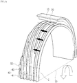
- FIG. 2A is a partial perspective view showing a sealing assembly according to a first exemplary embodiment
- FIG. 2B is a partial side view of FIG. 2A
- a sealing assembly according to the first exemplary embodiment may include a first sealing member 20 and a second sealing member 40.
- the first sealing member 20 may be disposed on an inner surface of a fixed body 10 of a turbine, for example, in a circumferential direction, and may have a ring shape.
- the fixed body 10 may be a diaphragm and a casing of the turbine on which the diaphragm is mounted, for example.
- the first sealing member 20 may be a honeycomb seal having a honeycomb structure (not shown).
- the second sealing member 40 may be disposed on an outer surface of a rotating body 30 in a circumferential direction while facing the first sealing member 20, and may have a ring shape.
- the rotating body 30 may be a bucket and a rotor of a turbine on which the bucket is mounted, for example.
- the second sealing member 40 may be a labyrinth seal having a plurality of protrusions formed thereon.
- the second sealing member 40 may include a sealing body part 41 and a tooth part 43.
- the sealing body part 41 may be mounted on the outer surface of the rotating body 30 of the turbine in the circumferential direction, and the tooth part 43 may be disposed on the sealing body part 41 to protrude therefrom.
- the tooth part 43 may be formed including a spiral S1 in a direction reverse to a direction in which the fluid is leaked.
- the spiral S1 is disposed on the sealing body part 41.
- the rotating body 30 rotates such as from a rotor driven in a turbine, for example, the second sealing member 40 mounted on the rotating body 30 rotates together therewith. Accordingly, as the spiral S1 rotates, the fluid leaked through the gap between the first sealing member 20 and the second sealing member 40 is moved back in the direction reverse to the direction in which the fluid is leaked. That is, as show in FIG. 2B , the leaked fluid flows in the circumferential direction along the spiral S1, and is returned to an introduction region F1 of the leaked fluid opposite region F2, thereby blocking the leakage of the fluid.
- the spiral S1 may be wound a plurality of times on the sealing body part 41 and integrally formed with the sealing body part 41.
- first sealing member 20 is a honeycomb seal
- second sealing member 40 is a labyrinth seal
- fluid pressure of the leaked fluid is basically decreased every time the leaked fluid passes through the honeycomb structure of the honeycomb seal and the plurality of protrusions of the labyrinth seal.
- the flow of the fluid is decreased toward a leakage region F2 of the leaked fluid from the introduction region F1, such that the leakage is blocked or minimized.
- the spiral S1 As illustrated in FIG. 2A , as the spiral S1 according to the exemplary embodiment is integrally wound a plurality of times on the sealing body part 41, the leaked fluid does not remain in the gap between the first sealing member 20 and the second sealing member 40. As the spiral S1 rotates in response to the rotation of the rotating part 30 of a rotor, for example, it is possible to effectively return the leaked fluid back to the introduction region F1 of the leaked fluid.
- the leaked fluid may be transferred in the direction reverse to the direction in which the fluid is leaked by the rotation of the spiral S1, and the fluid barrier is formed in the gap between the first sealing member 20 and the second sealing member 40 by using the air current generated by the rotation of the rotating body 30 of the turbine to hinder the leakage flow of the fluid, thereby ultimately preventing the leakage of the fluid.
- FIG. 3A is a partial perspective view showing a sealing assembly according to a second exemplary embodiment
- FIG. 3B is a partial side view of FIG. 3A
- a sealing assembly according to a second exemplary embodiment may include a first sealing member 20 and a second sealing member 40.
- the description of the disposition and the material for the first sealing member 20 and the second sealing member 40 is the same as that of the first exemplary embodiment, and thus will not be described again.
- the second sealing member 40 may include a sealing body part 41 and a tooth part 43.
- the sealing body part 41 may be mounted on the outer surface of the rotating body 30 in the circumferential direction, and the tooth part 43 may be disposed on the sealing body part 41 to protrude therefrom.
- the tooth part 43 may be formed including a spiral S2 in a direction reverse to a direction in which the fluid is leaked. Referring to FIGS. 3A and 3B , the spiral S2 is disposed on the sealing body part 41.
- the tooth part 43 according to the second exemplary embodiment is divided into two regions. One region has the spiral S2 formed thereon, and the other region has a circular ring C formed thereon.
- One or more circular rings C may be disposed at the leakage region F2 side of the leaked fluid on the sealing body part 41 in the circumferential direction.
- the circular ring C may have a protrusion shape, and when the circular ring C is disposed on the sealing body part 41 in plural, fluid pressure of the leaked fluid is decreased while the leaked fluid passes between the first sealing member 20 and the circular ring C. As a result, the leakage flow of the fluid is decreased, and the movement of the fluid toward the leakage region F2 of the leaked fluid is slowed down (A3 region in FIG. 3B ).
- the spiral S2 may be disposed at the introduction region F1 side of the leaked fluid on the sealing body part 41 (A2 region in FIG. 3B ).
- the spiral part S2 rotates in response to the rotation of the rotating body 30 of a rotor, for example, the fluid leaked through the gap between the first sealing member 20 and the second sealing member 40 is moved back in the direction reverse to the direction in which the fluid is leaked.
- the leaked fluid flows in the circumferential direction along the spiral S2, and is returned to the introduction region F1 of the leaked fluid, thereby blocking the leakage of the fluid.
- the spiral S2 is disposed closer to the introduction region F1 side of the leaked fluid on the sealing body part 41, and the circular ring C is disposed closer to the leakage region F2 side of the leaked fluid on the sealing body part 41.
- the spiral S2 may be wound a plurality of times on the sealing body part 41 and integrally formed with the sealing body part 41. Accordingly, the leaked fluid does not remain in the gap between the first sealing member 20 and the second sealing member 40, and as the spiral S2 rotates in response to the rotation of the rotating body 30, it is possible to effectively return the leaked fluid back to the introduction region F1 of the leaked fluid. As such, the leaked fluid may be transferred in the direction reverse to the direction in which the fluid is leaked by the rotation of the spiral part S2, and the fluid barrier (A2 region in FIG. 3B ) is formed in the gap between the first sealing member 20 and the second sealing member 40 by using the air current generated by the rotation of the rotating body 30 of the turbine to hinder the leakage flow of the fluid. Further, the fluid pressure of the fluid passing through the spiral part S2 is decreased at the circular ring C, such that the flow of the fluid is decreased to block the leakage, thereby ultimately preventing the leakage of the fluid.
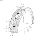
- FIG. 4A is a partial perspective view showing a sealing assembly according to a third exemplary embodiment
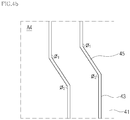
- FIG. 4B is a partially enlarged view of FIG. 4A
- a sealing assembly according to a third exemplary embodiment may include a first sealing member 20 and a second sealing member 40.
- the description of the disposition and the material for the first sealing member 20 and the second sealing member 40 is the same as that of the first exemplary embodiment, and thus will not be described again.
- the second sealing member 40 may include a sealing body part 41 and a tooth part 43.
- the sealing body part 41 may be mounted on the outer surface of the rotating body 30 in the circumferential direction, and the tooth part 43 may be disposed on the sealing body part 41 to protrude therefrom.
- the tooth part 43 may be formed including a spiral S3 in a direction reverse to a direction in which the fluid is leaked. Referring to FIGS. 4A and 4B , the spiral S3 is disposed on the sealing body part 41. Shape and function of the spiral S3 are the same as in the first exemplary embodiment, and thus will not be described again.
- the tooth part 43 may further include a step 45.
- the step 45 may be disposed on the sealing body part 41 so that the rotating fluid is pushed toward the introduction region F1 of the leaked fluid.
- the step 45 may be connected to the spiral S3 as illustrated in FIG. 4A . Accordingly, the fluid rotating and transferred along the spiral S3 may be moved while being pushed step by step toward the introduction region F1 of the leaked fluid by the step 45. Thus, the leaked fluid may be returned more rapidly in the reverse direction.
- the step 45 may be connected to the spiral S3 at a predetermined angle ( ⁇ 1 and ⁇ 2).
- the angle formed between the step 45 and the spiral S3 may be appropriately selected depending on the operational environment, such as a rotation speed of the rotor, characteristics of the operating fluid, etc.
- the angle ( ⁇ 1 and ⁇ 2) formed between the step 45 and the spiral S3 may be large in order to make the flow of the fluid smooth.
- the angle ( ⁇ 1 and ⁇ 2) formed between the step 45 and the spiral S3 may be small, such that the fluid is pushed further toward the introduction region F1 of the leaked fluid.
- the rotating fluid is pushed toward the introduction direction of the leaked fluid more rapidly through the step 45, such that the leaked fluid may be more quickly returned in the reverse direction.
- FIG. 5A is a partial perspective view showing a sealing assembly according to a fourth exemplary embodiment
- FIG. 5B is a partial side view of FIG. 5A
- a sealing assembly according to a fourth exemplary embodiment may include a first sealing member 20 and a second sealing member 40.
- the description of the disposition, the shape, and the material for the first sealing member 20 and the second sealing member 40 is the same as that of the first exemplary embodiment, and thus will not be described again.
- the second sealing member 40 may include a sealing body part 41, a tooth part 43, and a protrusion 50.
- the sealing body part 41 may be mounted on the outer surface of the rotating body 30 in the circumferential direction, and the tooth part 43 may be disposed on the sealing body part 41 to protrude therefrom.
- the tooth part 43 may be formed including a spiral S4 in a direction reverse to a direction in which the fluid is leaked. Referring to FIGS. 5A and 5B , the spiral S4 is disposed on the sealing body part 41. Shape and function of the spiral S4 are the same as in the first exemplary embodiment, and thus will not be described again.
- the second sealing member 40 further includes the protrusion 50.
- the protrusion 50 may be disposed on the sealing body part 41 connected with the tooth part 43 so that the fluid is pushed toward the outer side of the rotation direction.
- one or more protrusions 50 may be disposed in a row at a predetermined angle with the spiral S4, as illustrated in FIG. 5A .
- the protrusion part 50 is disposed perpendicularly to the spiral S4.
- Height L2 of the protrusion 50 is lower than height L1 of the spiral S4. If the height of the protrusion 50 is the same as or higher than the height of the spiral S4, the protrusion 50 hinders the flow of the fluid flowing between the spiral S4. Therefore, there may be a problem in transferring the leaked fluid toward the introduction direction of the leaked fluid again.
- the reinforced fluid barrier may be formed, such that the characteristic of the protrusion 50 is more clearly exhibited.
- the height of the protrusion part 50 is half or less of the height of the spiral part S4.
- the protrusion 50 may have a curved slope 50a formed on at least one side thereof so that the fluid is smoothly pushed toward the outer side of the rotation direction.
- the fluid is smoothly pushed toward the outer side along the curved slope 50a, thus the fluid barrier (A5 region in FIG. 5 ) may also be stably formed without an eddy phenomenon.
- the leakage of the fluid may be more thoroughly prevented by reinforcing the fluid barrier through the protrusion part 50.
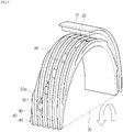
- FIG. 6 is a partial perspective view showing a sealing assembly according to a fifth exemplary embodiment.
- a sealing assembly according to a fifth exemplary embodiment may include a first sealing member 20 and a second sealing member 40.
- the description of the disposition, the shape, and the material for the first sealing member 20 and the second sealing member 40 is the same as that of the first exemplary embodiment, and thus will not be described again.
- the second sealing member 40 may include a sealing body part 41, a tooth part 43, and a protrusion 50.
- the sealing body part 41 may be mounted on the outer surface of the rotating body 30 in the circumferential direction, and the tooth part 43 may be disposed on the sealing body part 41 to protrude therefrom.
- the tooth part 43 may be formed including a spiral S5 in a direction reverse to a direction in which the fluid is leaked. Referring to FIG. 6 , the spiral S4 is disposed on the sealing body part 41. Shape and function of the spiral S5 are the same as in the first exemplary embodiment, and thus will not be described again.
- the second sealing member 40 further includes the protrusion 50.
- the protrusion 50 may be disposed on the sealing body part 41 connected with the tooth part 43 so that the fluid is pushed toward the outer side of the rotation direction.
- one or more protrusions 50 may be disposed at a predetermined angle with the spiral S5, as illustrated in FIG. 6 .
- the protrusion 50 may be disposed at different intervals between the spiral S5. Descriptions of the height of the protrusion 50 and the curved slope 50a are the same as in the fourth exemplary embodiment, thus will not be described again.
- the protrusion 50 rotates together therewith, and the fluid flowing between the spiral S5 is pushed toward the outer side direction by flowing over the protrusion 50.
- the fluid is pushed further toward the first sealing member 20, thus a stronger fluid barrier than that of the first exemplary embodiment may be formed.
- the fluid barrier hinders the flow of the fluid passing through the gap between the first sealing member 20 and the second sealing member 40 more strongly, thereby ultimately blocking the leakage of the fluid more thoroughly.
- the protrusion 50 are disposed at a predetermined interval between the spiral S5
- a reinforced fluid barrier is formed gradationally in the gap between the first sealing member 20 and the second sealing member 40 at different points, thereby hindering the leakage of the fluid.
- the leakage of the fluid may be ultimately prevented by gradationally reinforcing the fluid barrier through the protrusion 50 at different points.
Landscapes
- Engineering & Computer Science (AREA)
- General Engineering & Computer Science (AREA)
- Mechanical Engineering (AREA)
- Sealing Using Fluids, Sealing Without Contact, And Removal Of Oil (AREA)
- Turbine Rotor Nozzle Sealing (AREA)
- Chemical & Material Sciences (AREA)
- Combustion & Propulsion (AREA)
Claims (13)
- Assemblage d'étanchement, comprenant :un premier élément d'étanchement (20) disposé sur une surface circonférentielle intérieure d'un corps fixe (10) ;un second élément d'étanchement (40) disposé sur une surface circonférentielle extérieure d'un corps rotatif (30) configuré pour effectuer une rotation par rapport au premier élément d'étanchement (20) ;une barrière à fluide formée entre le premier élément d'étanchement (20) et le second élément d'étanchement (40) par un fluide de transfert qui s'écoule dans une direction inverse à une direction d'une fuite de fluide, dans lequel le second élément d'étanchement (40) inclut une partie de corps d'étanchement (41) disposée sur la surface circonférentielle extérieure du corps rotatif (30), et une partie dentée (43) disposée sur la partie de corps d'étanchement (41) et incluant une spirale pour former la barrière à fluide dans un intervalle entre le premier élément d'étanchement (20) et le second élément d'étanchement (40),caractérisé en ce que le second élément d'étanchement (40) inclut en outre une projection (50) connectée à la spirale configurée pour pousser le fluide vers un côté extérieur d'une direction de rotation.
- Assemblage d'étanchement selon la revendication 1,
dans lequel la spirale est enroulée une pluralité de fois autour de la partie de corps d'étanchement (41). - Assemblage d'étanchement selon la revendication 1 ou 2,
dans lequel la spirale est disposée sur un côté en direction d'introduction du fluide en train de fuir sur la partie de corps d'étanchement (41). - Assemblage d'étanchement selon l'une des revendications 1, 2 ou 3,
dans lequel la partie dentée (43) inclut en outre un gradin (45) disposé sur la partie de corps d'étanchement (41), configuré pour pousser le fluide en rotation vers le côté en direction d'introduction du fluide en train de fuir. - Assemblage d'étanchement selon la revendication 4,
dans lequel le gradin (45) est connecté à la spirale sous un angle prédéterminé. - Assemblage d'étanchement selon l'une quelconque des revendications 1 à 5,
dans lequel la projection (50) est formée sous un angle prédéterminé avec la spirale. - Assemblage d'étanchement selon l'une quelconque des revendications précédentes 1 à 6,
dans lequel la projection (50) est disposée entre la spirale. - Assemblage d'étanchement selon l'une quelconque des revendications précédentes 1 à 7,
dans lequel une pluralité de projections (50) sont positionnées dans une rangée entre la spirale. - Assemblage d'étanchement selon l'une quelconque des revendications 1 à 8,
dans lequel une pluralité de projections (50) sont positionnées à un intervalle prédéterminé entre la spirale. - Assemblage d'étanchement selon l'une quelconque des revendications précédentes 1 à 9,
dans lequel la projection (50) inclut une pente incurvée (50a) sur au moins un côté d'elle-même. - Assemblage d'étanchement selon l'une quelconque des revendications précédentes,
dans lequel une hauteur de la partie en projection (50) est inférieure à une hauteur de la spirale. - Assemblage d'étanchement selon l'une quelconque des revendications précédentes 1 à 11,
dans lequel la partie dentée (41) inclut en outre une ou plusieurs bagues circulaires. - Assemblage d'étanchement selon la revendication 12,
dans lequel lesdites une ou plusieurs bagues circulaires sont disposées sur un côté en direction de fuite du fluide en train de fuir sur la partie de corps d'étanchement (41).
Applications Claiming Priority (1)
| Application Number | Priority Date | Filing Date | Title |
|---|---|---|---|
| KR1020150148307A KR101730261B1 (ko) | 2015-10-23 | 2015-10-23 | 터빈의 실링 조립체 |
Publications (2)
| Publication Number | Publication Date |
|---|---|
| EP3159491A1 EP3159491A1 (fr) | 2017-04-26 |
| EP3159491B1 true EP3159491B1 (fr) | 2018-12-12 |
Family
ID=57209221
Family Applications (1)
| Application Number | Title | Priority Date | Filing Date |
|---|---|---|---|
| EP16195134.8A Active EP3159491B1 (fr) | 2015-10-23 | 2016-10-21 | Ensemble d'étanchéité de turbine |
Country Status (4)
| Country | Link |
|---|---|
| US (1) | US10480339B2 (fr) |
| EP (1) | EP3159491B1 (fr) |
| KR (1) | KR101730261B1 (fr) |
| WO (1) | WO2017069582A1 (fr) |
Families Citing this family (12)
| Publication number | Priority date | Publication date | Assignee | Title |
|---|---|---|---|---|
| US10584795B2 (en) * | 2017-03-29 | 2020-03-10 | Florida Turbine Technologies, Inc. | Interlocking axial labyrinth seal |
| US11242804B2 (en) * | 2017-06-14 | 2022-02-08 | General Electric Company | Inleakage management apparatus |
| KR101985093B1 (ko) * | 2017-09-12 | 2019-05-31 | 두산중공업 주식회사 | 블레이드 팁의 실링구조와 이를 포함하는 가스터빈 |
| DE102018119463B4 (de) | 2018-08-09 | 2023-12-28 | Rolls-Royce Deutschland Ltd & Co Kg | Labyrinthdichtungssystem und Gasturbinentriebwerk mit einem Labyrinthdichtungssystem |
| JP2020066090A (ja) * | 2018-10-24 | 2020-04-30 | 株式会社北川鉄工所 | 非接触シール構造体の製造方法、及び回転機械 |
| JP7185503B2 (ja) * | 2018-11-16 | 2022-12-07 | 株式会社東芝 | 流体機械及び流体機械の改修方法 |
| JP2020133600A (ja) * | 2019-02-26 | 2020-08-31 | 株式会社日立インダストリアルプロダクツ | 遠心圧縮機 |
| US11248492B2 (en) * | 2019-03-18 | 2022-02-15 | Raytheon Technologies Corporation | Seal assembly for a gas turbine engine |
| JP7530104B2 (ja) * | 2021-04-09 | 2024-08-07 | 国立研究開発法人宇宙航空研究開発機構 | ラビリンスシール |
| CN113090338A (zh) * | 2021-05-10 | 2021-07-09 | 西安热工研究院有限公司 | 用于二氧化碳透平的反旋向螺纹对冲式气封结构及气封方法 |
| KR102844942B1 (ko) | 2023-12-27 | 2025-08-11 | 터보파워텍(주) | 터빈용 필름라이딩 씰의 제조방법 |
| US12460655B2 (en) * | 2024-03-11 | 2025-11-04 | Honeywell International Inc. | Helical seal for multi-stage compressor |
Family Cites Families (30)
| Publication number | Priority date | Publication date | Assignee | Title |
|---|---|---|---|---|
| US450004A (en) * | 1891-04-07 | Journal-bearing | ||
| DE668667C (de) * | 1938-12-08 | Oerlikon Maschf | Vorrichtung zur Verminderung der Dampfverluste bei Labyrinthdichtungen fuer umlaufende Wellen | |
| US1189457A (en) * | 1914-05-19 | 1916-07-04 | Howard S Levy | Etching-machine. |
| US2109680A (en) * | 1936-04-13 | 1938-03-01 | Sr Aloys Neveling | Sealing device for pumps |
| US3131942A (en) * | 1958-09-15 | 1964-05-05 | Alsacienne Constr Meca | Fluid-tight devices for rotating shafts |
| US3355179A (en) * | 1964-08-24 | 1967-11-28 | Gen Electric | Gas buffered screw seal |
| GB1302198A (fr) * | 1969-05-09 | 1973-01-04 | ||
| US3661400A (en) * | 1970-10-08 | 1972-05-09 | Gen Motors Corp | Hydrodynamic seal with leakage control rib |
| US3700247A (en) * | 1971-08-16 | 1972-10-24 | May V Latinen | Flush cooling of shaft sealing screw means |
| US3795386A (en) * | 1971-08-16 | 1974-03-05 | Monsanto Co | Shaft seal for low and high pressures |
| FR2288909A1 (fr) * | 1974-10-21 | 1976-05-21 | Activite Atom Avance | Joint tournant d'etancheite par effet visqueux |
| US4305592A (en) * | 1979-10-23 | 1981-12-15 | Transamerica Delaval, Inc. | Gas seal bushing |
| US4368895A (en) * | 1980-12-01 | 1983-01-18 | Mitsubishi Denki Kabushiki Kaisha | Shaft sealing device utilizing a non-uniform groove depth |
| EP0131286B1 (fr) * | 1983-07-08 | 1988-11-30 | Tanken Seiko Corporation | Joint d'étanchéité pour l'étanchement d'un liquide boueux |
| US5639095A (en) * | 1988-01-04 | 1997-06-17 | Twentieth Technology | Low-leakage and low-instability labyrinth seal |
| US5029876A (en) * | 1988-12-14 | 1991-07-09 | General Electric Company | Labyrinth seal system |
| JPH0953411A (ja) | 1995-08-16 | 1997-02-25 | Fuji Electric Co Ltd | 対向フィン形ラビリンスシール |
| JP3567064B2 (ja) * | 1997-06-23 | 2004-09-15 | 株式会社 日立インダストリイズ | ラビリンスシール装置及びそれを備えた流体機械 |
| JPH11200810A (ja) * | 1998-01-09 | 1999-07-27 | Mitsubishi Heavy Ind Ltd | ラビリンスシール機構 |
| DE10033446C5 (de) * | 2000-07-10 | 2006-12-14 | Dichtungstechnik G. Bruss Gmbh & Co. Kg | Wellendichtring |
| JP2002228005A (ja) * | 2000-11-29 | 2002-08-14 | Toyota Industries Corp | 軸封装置及び圧縮機 |
| DE10109320C2 (de) * | 2001-02-27 | 2003-07-10 | Bruss Dichtungstechnik | Radialwellendichtring |
| US7004475B2 (en) * | 2003-09-26 | 2006-02-28 | Siemens Westinghouse Power Corporation | Flow dam design for labyrinth seals to promote rotor stability |
| US7419165B2 (en) * | 2004-08-18 | 2008-09-02 | Federal-Mogul World Wide, Inc. | Seal assembly and method of manufacturing the same |
| US8066475B2 (en) * | 2007-09-04 | 2011-11-29 | General Electric Company | Labyrinth compression seal and turbine incorporating the same |
| US9068571B2 (en) * | 2009-04-03 | 2015-06-30 | Ergoseal, Inc. | Seal for oil-free rotary displacement compressor |
| US9074486B2 (en) * | 2011-01-31 | 2015-07-07 | General Electric Company | Method and apparatus for labyrinth seal packing ring |
| DE202011105609U1 (de) | 2011-09-12 | 2011-10-13 | Alstom Technology Ltd. | Labyrinthdichtung |
| ITCO20120019A1 (it) * | 2012-04-27 | 2013-10-28 | Nuovo Pignone Srl | Tenute a labirinto ad alto smorzamento con sagoma elicoidale e mista elicoidale-cilindrica |
| US9506366B2 (en) | 2013-08-06 | 2016-11-29 | General Electric Company | Helical seal system for a turbomachine |
-
2015
- 2015-10-23 KR KR1020150148307A patent/KR101730261B1/ko active Active
-
2016
- 2016-10-21 WO PCT/KR2016/011930 patent/WO2017069582A1/fr not_active Ceased
- 2016-10-21 US US15/299,682 patent/US10480339B2/en active Active
- 2016-10-21 EP EP16195134.8A patent/EP3159491B1/fr active Active
Non-Patent Citations (1)
| Title |
|---|
| None * |
Also Published As
| Publication number | Publication date |
|---|---|
| WO2017069582A1 (fr) | 2017-04-27 |
| US10480339B2 (en) | 2019-11-19 |
| EP3159491A1 (fr) | 2017-04-26 |
| KR101730261B1 (ko) | 2017-04-25 |
| US20170114655A1 (en) | 2017-04-27 |
Similar Documents
| Publication | Publication Date | Title |
|---|---|---|
| US10480339B2 (en) | Sealing assembly | |
| JP5693529B2 (ja) | ラビリンスシール | |
| JP6220191B2 (ja) | ターボ機械用のシール設計構造及びアクティブクリアランス制御方法 | |
| EP3078888B1 (fr) | Structure de joint et machine rotative | |
| JP6216643B2 (ja) | スワール阻止シールを有するターボ機械 | |
| EP2427676B1 (fr) | Dispositif d'etancheite et procede pour turbines a vapeur | |
| US10837301B2 (en) | Structure for multi-stage sealing of turbine | |
| KR19990063333A (ko) | 비접촉식으로 회전자와 고정자 간에 형성된 분리 갭을 밀봉하기 위한 방법 및 장치 | |
| JP2003106105A (ja) | 軸シール機構及びタービン | |
| US20100054924A1 (en) | Brush seal and turbine using the same | |
| KR20030035993A (ko) | 환상 시일 링 조립체용 패킹 부품 및 터빈 노즐다이어프램용 환상 시일 링 조립체 | |
| US20100196139A1 (en) | Leakage flow minimization system for a turbine engine | |
| US20120121411A1 (en) | Labyrinth Seals for Turbomachinery | |
| KR102153065B1 (ko) | 링 세그먼트 및 이를 포함하는 가스 터빈 | |
| KR101950924B1 (ko) | 터빈용 복합 실링장치 | |
| CN110242360B (zh) | 动叶片侧密封装置、静叶片侧密封装置及旋转机械 | |
| CN107614948B (zh) | 密封装置以及旋转机械 | |
| EP3159488B1 (fr) | Ensemble d'étanchéité et turbine associée | |
| JP2014141912A (ja) | 回転機械 | |
| CN110318818A (zh) | 涡轮机动叶片以及旋转机械 | |
| JP2007321721A (ja) | 軸流タービン段落および軸流タービン | |
| JP2011106474A (ja) | 軸流タービン段落および軸流タービン | |
| JP4371610B2 (ja) | 蒸気タービンのシール装置 | |
| EP1519010A1 (fr) | Joint externe d'étanchéité à l'air | |
| CN108699915B (zh) | 密封构造及涡轮机械 |
Legal Events
| Date | Code | Title | Description |
|---|---|---|---|
| PUAI | Public reference made under article 153(3) epc to a published international application that has entered the european phase |
Free format text: ORIGINAL CODE: 0009012 |
|
| STAA | Information on the status of an ep patent application or granted ep patent |
Free format text: STATUS: REQUEST FOR EXAMINATION WAS MADE |
|
| 17P | Request for examination filed |
Effective date: 20161021 |
|
| AK | Designated contracting states |
Kind code of ref document: A1 Designated state(s): AL AT BE BG CH CY CZ DE DK EE ES FI FR GB GR HR HU IE IS IT LI LT LU LV MC MK MT NL NO PL PT RO RS SE SI SK SM TR |
|
| AX | Request for extension of the european patent |
Extension state: BA ME |
|
| RBV | Designated contracting states (corrected) |
Designated state(s): AL AT BE BG CH CY CZ DE DK EE ES FI FR GB GR HR HU IE IS IT LI LT LU LV MC MK MT NL NO PL PT RO RS SE SI SK SM TR |
|
| REG | Reference to a national code |
Ref country code: DE Ref legal event code: R079 Ref document number: 602016008104 Country of ref document: DE Free format text: PREVIOUS MAIN CLASS: F01D0011040000 Ipc: F01D0011020000 |
|
| RIC1 | Information provided on ipc code assigned before grant |
Ipc: F01D 11/02 20060101AFI20180323BHEP Ipc: F16J 15/40 20060101ALI20180323BHEP Ipc: F01D 11/04 20060101ALI20180323BHEP Ipc: F16J 15/447 20060101ALI20180323BHEP |
|
| GRAP | Despatch of communication of intention to grant a patent |
Free format text: ORIGINAL CODE: EPIDOSNIGR1 |
|
| STAA | Information on the status of an ep patent application or granted ep patent |
Free format text: STATUS: GRANT OF PATENT IS INTENDED |
|
| INTG | Intention to grant announced |
Effective date: 20180528 |
|
| GRAS | Grant fee paid |
Free format text: ORIGINAL CODE: EPIDOSNIGR3 |
|
| GRAA | (expected) grant |
Free format text: ORIGINAL CODE: 0009210 |
|
| STAA | Information on the status of an ep patent application or granted ep patent |
Free format text: STATUS: THE PATENT HAS BEEN GRANTED |
|
| AK | Designated contracting states |
Kind code of ref document: B1 Designated state(s): AL AT BE BG CH CY CZ DE DK EE ES FI FR GB GR HR HU IE IS IT LI LT LU LV MC MK MT NL NO PL PT RO RS SE SI SK SM TR |
|
| REG | Reference to a national code |
Ref country code: GB Ref legal event code: FG4D |
|
| REG | Reference to a national code |
Ref country code: CH Ref legal event code: EP |
|
| REG | Reference to a national code |
Ref country code: AT Ref legal event code: REF Ref document number: 1076258 Country of ref document: AT Kind code of ref document: T Effective date: 20181215 |
|
| REG | Reference to a national code |
Ref country code: DE Ref legal event code: R096 Ref document number: 602016008104 Country of ref document: DE |
|
| REG | Reference to a national code |
Ref country code: IE Ref legal event code: FG4D |
|
| REG | Reference to a national code |
Ref country code: NL Ref legal event code: MP Effective date: 20181212 |
|
| REG | Reference to a national code |
Ref country code: LT Ref legal event code: MG4D |
|
| PG25 | Lapsed in a contracting state [announced via postgrant information from national office to epo] |
Ref country code: FI Free format text: LAPSE BECAUSE OF FAILURE TO SUBMIT A TRANSLATION OF THE DESCRIPTION OR TO PAY THE FEE WITHIN THE PRESCRIBED TIME-LIMIT Effective date: 20181212 Ref country code: LT Free format text: LAPSE BECAUSE OF FAILURE TO SUBMIT A TRANSLATION OF THE DESCRIPTION OR TO PAY THE FEE WITHIN THE PRESCRIBED TIME-LIMIT Effective date: 20181212 Ref country code: BG Free format text: LAPSE BECAUSE OF FAILURE TO SUBMIT A TRANSLATION OF THE DESCRIPTION OR TO PAY THE FEE WITHIN THE PRESCRIBED TIME-LIMIT Effective date: 20190312 Ref country code: HR Free format text: LAPSE BECAUSE OF FAILURE TO SUBMIT A TRANSLATION OF THE DESCRIPTION OR TO PAY THE FEE WITHIN THE PRESCRIBED TIME-LIMIT Effective date: 20181212 Ref country code: ES Free format text: LAPSE BECAUSE OF FAILURE TO SUBMIT A TRANSLATION OF THE DESCRIPTION OR TO PAY THE FEE WITHIN THE PRESCRIBED TIME-LIMIT Effective date: 20181212 Ref country code: LV Free format text: LAPSE BECAUSE OF FAILURE TO SUBMIT A TRANSLATION OF THE DESCRIPTION OR TO PAY THE FEE WITHIN THE PRESCRIBED TIME-LIMIT Effective date: 20181212 Ref country code: NO Free format text: LAPSE BECAUSE OF FAILURE TO SUBMIT A TRANSLATION OF THE DESCRIPTION OR TO PAY THE FEE WITHIN THE PRESCRIBED TIME-LIMIT Effective date: 20190312 |
|
| REG | Reference to a national code |
Ref country code: AT Ref legal event code: MK05 Ref document number: 1076258 Country of ref document: AT Kind code of ref document: T Effective date: 20181212 |
|
| PG25 | Lapsed in a contracting state [announced via postgrant information from national office to epo] |
Ref country code: AL Free format text: LAPSE BECAUSE OF FAILURE TO SUBMIT A TRANSLATION OF THE DESCRIPTION OR TO PAY THE FEE WITHIN THE PRESCRIBED TIME-LIMIT Effective date: 20181212 Ref country code: RS Free format text: LAPSE BECAUSE OF FAILURE TO SUBMIT A TRANSLATION OF THE DESCRIPTION OR TO PAY THE FEE WITHIN THE PRESCRIBED TIME-LIMIT Effective date: 20181212 Ref country code: GR Free format text: LAPSE BECAUSE OF FAILURE TO SUBMIT A TRANSLATION OF THE DESCRIPTION OR TO PAY THE FEE WITHIN THE PRESCRIBED TIME-LIMIT Effective date: 20190313 Ref country code: SE Free format text: LAPSE BECAUSE OF FAILURE TO SUBMIT A TRANSLATION OF THE DESCRIPTION OR TO PAY THE FEE WITHIN THE PRESCRIBED TIME-LIMIT Effective date: 20181212 |
|
| PG25 | Lapsed in a contracting state [announced via postgrant information from national office to epo] |
Ref country code: NL Free format text: LAPSE BECAUSE OF FAILURE TO SUBMIT A TRANSLATION OF THE DESCRIPTION OR TO PAY THE FEE WITHIN THE PRESCRIBED TIME-LIMIT Effective date: 20181212 |
|
| PG25 | Lapsed in a contracting state [announced via postgrant information from national office to epo] |
Ref country code: CZ Free format text: LAPSE BECAUSE OF FAILURE TO SUBMIT A TRANSLATION OF THE DESCRIPTION OR TO PAY THE FEE WITHIN THE PRESCRIBED TIME-LIMIT Effective date: 20181212 Ref country code: PT Free format text: LAPSE BECAUSE OF FAILURE TO SUBMIT A TRANSLATION OF THE DESCRIPTION OR TO PAY THE FEE WITHIN THE PRESCRIBED TIME-LIMIT Effective date: 20190412 Ref country code: IT Free format text: LAPSE BECAUSE OF FAILURE TO SUBMIT A TRANSLATION OF THE DESCRIPTION OR TO PAY THE FEE WITHIN THE PRESCRIBED TIME-LIMIT Effective date: 20181212 Ref country code: PL Free format text: LAPSE BECAUSE OF FAILURE TO SUBMIT A TRANSLATION OF THE DESCRIPTION OR TO PAY THE FEE WITHIN THE PRESCRIBED TIME-LIMIT Effective date: 20181212 |
|
| PG25 | Lapsed in a contracting state [announced via postgrant information from national office to epo] |
Ref country code: RO Free format text: LAPSE BECAUSE OF FAILURE TO SUBMIT A TRANSLATION OF THE DESCRIPTION OR TO PAY THE FEE WITHIN THE PRESCRIBED TIME-LIMIT Effective date: 20181212 Ref country code: SK Free format text: LAPSE BECAUSE OF FAILURE TO SUBMIT A TRANSLATION OF THE DESCRIPTION OR TO PAY THE FEE WITHIN THE PRESCRIBED TIME-LIMIT Effective date: 20181212 Ref country code: IS Free format text: LAPSE BECAUSE OF FAILURE TO SUBMIT A TRANSLATION OF THE DESCRIPTION OR TO PAY THE FEE WITHIN THE PRESCRIBED TIME-LIMIT Effective date: 20190412 Ref country code: SM Free format text: LAPSE BECAUSE OF FAILURE TO SUBMIT A TRANSLATION OF THE DESCRIPTION OR TO PAY THE FEE WITHIN THE PRESCRIBED TIME-LIMIT Effective date: 20181212 Ref country code: EE Free format text: LAPSE BECAUSE OF FAILURE TO SUBMIT A TRANSLATION OF THE DESCRIPTION OR TO PAY THE FEE WITHIN THE PRESCRIBED TIME-LIMIT Effective date: 20181212 |
|
| REG | Reference to a national code |
Ref country code: DE Ref legal event code: R097 Ref document number: 602016008104 Country of ref document: DE |
|
| PLBE | No opposition filed within time limit |
Free format text: ORIGINAL CODE: 0009261 |
|
| STAA | Information on the status of an ep patent application or granted ep patent |
Free format text: STATUS: NO OPPOSITION FILED WITHIN TIME LIMIT |
|
| PG25 | Lapsed in a contracting state [announced via postgrant information from national office to epo] |
Ref country code: DK Free format text: LAPSE BECAUSE OF FAILURE TO SUBMIT A TRANSLATION OF THE DESCRIPTION OR TO PAY THE FEE WITHIN THE PRESCRIBED TIME-LIMIT Effective date: 20181212 Ref country code: AT Free format text: LAPSE BECAUSE OF FAILURE TO SUBMIT A TRANSLATION OF THE DESCRIPTION OR TO PAY THE FEE WITHIN THE PRESCRIBED TIME-LIMIT Effective date: 20181212 Ref country code: SI Free format text: LAPSE BECAUSE OF FAILURE TO SUBMIT A TRANSLATION OF THE DESCRIPTION OR TO PAY THE FEE WITHIN THE PRESCRIBED TIME-LIMIT Effective date: 20181212 |
|
| 26N | No opposition filed |
Effective date: 20190913 |
|
| PG25 | Lapsed in a contracting state [announced via postgrant information from national office to epo] |
Ref country code: TR Free format text: LAPSE BECAUSE OF FAILURE TO SUBMIT A TRANSLATION OF THE DESCRIPTION OR TO PAY THE FEE WITHIN THE PRESCRIBED TIME-LIMIT Effective date: 20181212 |
|
| PG25 | Lapsed in a contracting state [announced via postgrant information from national office to epo] |
Ref country code: MC Free format text: LAPSE BECAUSE OF FAILURE TO SUBMIT A TRANSLATION OF THE DESCRIPTION OR TO PAY THE FEE WITHIN THE PRESCRIBED TIME-LIMIT Effective date: 20181212 |
|
| REG | Reference to a national code |
Ref country code: CH Ref legal event code: PL |
|
| PG25 | Lapsed in a contracting state [announced via postgrant information from national office to epo] |
Ref country code: CH Free format text: LAPSE BECAUSE OF NON-PAYMENT OF DUE FEES Effective date: 20191031 Ref country code: LI Free format text: LAPSE BECAUSE OF NON-PAYMENT OF DUE FEES Effective date: 20191031 Ref country code: LU Free format text: LAPSE BECAUSE OF NON-PAYMENT OF DUE FEES Effective date: 20191021 |
|
| REG | Reference to a national code |
Ref country code: BE Ref legal event code: MM Effective date: 20191031 |
|
| PG25 | Lapsed in a contracting state [announced via postgrant information from national office to epo] |
Ref country code: BE Free format text: LAPSE BECAUSE OF NON-PAYMENT OF DUE FEES Effective date: 20191031 |
|
| PG25 | Lapsed in a contracting state [announced via postgrant information from national office to epo] |
Ref country code: IE Free format text: LAPSE BECAUSE OF NON-PAYMENT OF DUE FEES Effective date: 20191021 Ref country code: FR Free format text: LAPSE BECAUSE OF NON-PAYMENT OF DUE FEES Effective date: 20191031 |
|
| PG25 | Lapsed in a contracting state [announced via postgrant information from national office to epo] |
Ref country code: CY Free format text: LAPSE BECAUSE OF FAILURE TO SUBMIT A TRANSLATION OF THE DESCRIPTION OR TO PAY THE FEE WITHIN THE PRESCRIBED TIME-LIMIT Effective date: 20181212 |
|
| PG25 | Lapsed in a contracting state [announced via postgrant information from national office to epo] |
Ref country code: HU Free format text: LAPSE BECAUSE OF FAILURE TO SUBMIT A TRANSLATION OF THE DESCRIPTION OR TO PAY THE FEE WITHIN THE PRESCRIBED TIME-LIMIT; INVALID AB INITIO Effective date: 20161021 Ref country code: MT Free format text: LAPSE BECAUSE OF FAILURE TO SUBMIT A TRANSLATION OF THE DESCRIPTION OR TO PAY THE FEE WITHIN THE PRESCRIBED TIME-LIMIT Effective date: 20181212 |
|
| PG25 | Lapsed in a contracting state [announced via postgrant information from national office to epo] |
Ref country code: MK Free format text: LAPSE BECAUSE OF FAILURE TO SUBMIT A TRANSLATION OF THE DESCRIPTION OR TO PAY THE FEE WITHIN THE PRESCRIBED TIME-LIMIT Effective date: 20181212 |
|
| PGFP | Annual fee paid to national office [announced via postgrant information from national office to epo] |
Ref country code: GB Payment date: 20250828 Year of fee payment: 10 |
|
| PGFP | Annual fee paid to national office [announced via postgrant information from national office to epo] |
Ref country code: DE Payment date: 20250827 Year of fee payment: 10 |