EP3159504A1 - Axialturbine mit radialer anströmung und turbolader - Google Patents
Axialturbine mit radialer anströmung und turbolader Download PDFInfo
- Publication number
- EP3159504A1 EP3159504A1 EP16194815.3A EP16194815A EP3159504A1 EP 3159504 A1 EP3159504 A1 EP 3159504A1 EP 16194815 A EP16194815 A EP 16194815A EP 3159504 A1 EP3159504 A1 EP 3159504A1
- Authority
- EP
- European Patent Office
- Prior art keywords
- turbine
- tip
- axial direction
- radial
- axial flow
- Prior art date
- Legal status (The legal status is an assumption and is not a legal conclusion. Google has not performed a legal analysis and makes no representation as to the accuracy of the status listed.)
- Granted
Links
Images





Classifications
-
- F—MECHANICAL ENGINEERING; LIGHTING; HEATING; WEAPONS; BLASTING
- F01—MACHINES OR ENGINES IN GENERAL; ENGINE PLANTS IN GENERAL; STEAM ENGINES
- F01D—NON-POSITIVE DISPLACEMENT MACHINES OR ENGINES, e.g. STEAM TURBINES
- F01D11/00—Preventing or minimising internal leakage of working-fluid, e.g. between stages
- F01D11/08—Preventing or minimising internal leakage of working-fluid, e.g. between stages for sealing space between rotor blade tips and stator
-
- F—MECHANICAL ENGINEERING; LIGHTING; HEATING; WEAPONS; BLASTING
- F01—MACHINES OR ENGINES IN GENERAL; ENGINE PLANTS IN GENERAL; STEAM ENGINES
- F01D—NON-POSITIVE DISPLACEMENT MACHINES OR ENGINES, e.g. STEAM TURBINES
- F01D1/00—Non-positive-displacement machines or engines, e.g. steam turbines
- F01D1/02—Non-positive-displacement machines or engines, e.g. steam turbines with stationary working-fluid guiding means and bladed or like rotor, e.g. multi-bladed impulse steam turbines
- F01D1/04—Non-positive-displacement machines or engines, e.g. steam turbines with stationary working-fluid guiding means and bladed or like rotor, e.g. multi-bladed impulse steam turbines traversed by the working-fluid substantially axially
-
- F—MECHANICAL ENGINEERING; LIGHTING; HEATING; WEAPONS; BLASTING
- F01—MACHINES OR ENGINES IN GENERAL; ENGINE PLANTS IN GENERAL; STEAM ENGINES
- F01D—NON-POSITIVE DISPLACEMENT MACHINES OR ENGINES, e.g. STEAM TURBINES
- F01D1/00—Non-positive-displacement machines or engines, e.g. steam turbines
- F01D1/18—Non-positive-displacement machines or engines, e.g. steam turbines without stationary working-fluid guiding means
- F01D1/20—Non-positive-displacement machines or engines, e.g. steam turbines without stationary working-fluid guiding means traversed by the working-fluid substantially axially
-
- F—MECHANICAL ENGINEERING; LIGHTING; HEATING; WEAPONS; BLASTING
- F01—MACHINES OR ENGINES IN GENERAL; ENGINE PLANTS IN GENERAL; STEAM ENGINES
- F01D—NON-POSITIVE DISPLACEMENT MACHINES OR ENGINES, e.g. STEAM TURBINES
- F01D9/00—Stators
- F01D9/02—Nozzles; Nozzle boxes; Stator blades; Guide conduits, e.g. individual nozzles
-
- F—MECHANICAL ENGINEERING; LIGHTING; HEATING; WEAPONS; BLASTING
- F02—COMBUSTION ENGINES; HOT-GAS OR COMBUSTION-PRODUCT ENGINE PLANTS
- F02B—INTERNAL-COMBUSTION PISTON ENGINES; COMBUSTION ENGINES IN GENERAL
- F02B39/00—Component parts, details, or accessories relating to, driven charging or scavenging pumps, not provided for in groups F02B33/00 - F02B37/00
-
- F—MECHANICAL ENGINEERING; LIGHTING; HEATING; WEAPONS; BLASTING
- F02—COMBUSTION ENGINES; HOT-GAS OR COMBUSTION-PRODUCT ENGINE PLANTS
- F02C—GAS-TURBINE PLANTS; AIR INTAKES FOR JET-PROPULSION PLANTS; CONTROLLING FUEL SUPPLY IN AIR-BREATHING JET-PROPULSION PLANTS
- F02C6/00—Plural gas-turbine plants; Combinations of gas-turbine plants with other apparatus; Adaptations of gas-turbine plants for special use
- F02C6/04—Gas-turbine plants providing heated or pressurised working fluid for other apparatus, e.g. without mechanical power output
- F02C6/10—Gas-turbine plants providing heated or pressurised working fluid for other apparatus, e.g. without mechanical power output supplying working fluid to a user, e.g. a chemical process, which returns working fluid to a turbine of the plant
- F02C6/12—Turbochargers, i.e. plants for augmenting mechanical power output of internal-combustion piston engines by increase of charge pressure
-
- F—MECHANICAL ENGINEERING; LIGHTING; HEATING; WEAPONS; BLASTING
- F05—INDEXING SCHEMES RELATING TO ENGINES OR PUMPS IN VARIOUS SUBCLASSES OF CLASSES F01-F04
- F05D—INDEXING SCHEME FOR ASPECTS RELATING TO NON-POSITIVE-DISPLACEMENT MACHINES OR ENGINES, GAS-TURBINES OR JET-PROPULSION PLANTS
- F05D2220/00—Application
- F05D2220/40—Application in turbochargers
-
- F—MECHANICAL ENGINEERING; LIGHTING; HEATING; WEAPONS; BLASTING
- F05—INDEXING SCHEMES RELATING TO ENGINES OR PUMPS IN VARIOUS SUBCLASSES OF CLASSES F01-F04
- F05D—INDEXING SCHEME FOR ASPECTS RELATING TO NON-POSITIVE-DISPLACEMENT MACHINES OR ENGINES, GAS-TURBINES OR JET-PROPULSION PLANTS
- F05D2240/00—Components
- F05D2240/20—Rotors
- F05D2240/30—Characteristics of rotor blades, i.e. of any element transforming dynamic fluid energy to or from rotational energy and being attached to a rotor
- F05D2240/307—Characteristics of rotor blades, i.e. of any element transforming dynamic fluid energy to or from rotational energy and being attached to a rotor related to the tip of a rotor blade
Definitions
- the present disclosure relates to an axial flow turbine of radial-inflow type and a turbocharger.
- an axial flow turbine of radial-inflow type which causes working fluid to flow in an axial direction to act on turbine blades of a turbine wheel and rotates the turbine wheel has been developed.
- Such an axial flow turbine of radial-inflow type is, for instance, considered to be advantageous in a small supercharger such as a turbocharger for an automobile, whose turbo rug is desired to be reduced by decreasing inertia.
- Patent Document 1 discloses a turbocharger including an axial flow turbine of radial-inflow type configured such that exhaust gas from a scroll part acts on leading edges of turbine blades substantially in the axial direction.
- Patent Document 2 discloses a mixed flow turbine for a supercharger configured to direct exhaust gas from a scroll chamber to a turbine impeller with a leading edge part formed diagonally to the axial direction.
- the mixed flow turbine has an intermediate property between a radial flow turbine and an axial flow turbine.
- a pressure differential is created between a pressure surface side (concave side) and a suction surface side (convex side) of a turbine blade.
- the pressure differential may act as a driving force that causes leakage (tip leakage) of working fluid via the tip clearance.
- the ratio of the tip clearance to the blade length (blade height) tends to become so large that a decrease in the turbine efficiency due to tip leakage cannot be ignored.
- the size of the tip clearance is set taking account of vibration predicted to occur during operation of the axial flow turbine and machining accuracy of a bearing that rotatably supports a rotation shaft of the axial flow turbine, for instance. Therefore, there is a limit in reducing the tip clearance in accordance with a decrease in the blade length, and thus the tip clearance becomes large relative to the blade length of the turbine blades in a small axial flow turbine.
- Patent Document 1 does not disclose a configuration for suppressing tip leakage in an axial flow turbine.
- Patent Document 2 the turbine for a supercharger described in Patent Document 2 is not an axial flow turbine but a mixed flow turbine, and thus the flow of exhaust gas directed to the turbine blades from the scroll chamber is considerably different from that of an axial flow turbine.
- Patent Document 2 does not even suggest a configuration for suppressing tip leakage in an axial flow turbine.
- an object of some embodiments of the present invention is to provide an axial flow turbine of radial-inflow type whereby it is possible to suppress a decrease in turbine efficiency due to tip leakage, and a turbocharger having the same.
- An axial flow turbine of radial-inflow type is for recovering power from energy of working fluid, and comprises: a rotation shaft extending in an axial direction of the axial flow turbine; a turbine wheel including a plurality of turbine blades each extending from a blade root (hub) to a blade tip (tip) outwardly in a radial direction of the axial flow turbine, the turbine wheel being configured to rotate together with the rotation shaft; and a housing including a scroll part for swirling the working fluid flowing into the housing along a circumferential direction of the rotation shaft and a bend part for changing a flow direction of the working fluid flowing inwardly in the radial direction from the scroll part into a direction along the axial direction to direct the flow of the working fluid to the turbine blades.
- the bend part includes a tip-side inner wall surface of a bend shape at least in a region at an upstream side, in the axial direction, of a portion of a leading edge of the turbine blades, the portion being adjacent to a hub (the tip-side inner wall surface is a portion of the inner wall surface of the bend part at the outer side in the radial direction of the axial flow turbine, the portion being adjacent to the tip).
- the bend shape of the tip-side inner wall surface of the bend part, along the axial direction has the minimum curvature radius at the position X Z , in the axial direction, in the vicinity of the leading edge of the turbine blades.
- the centrifugal force due to the minimum curvature radius forms a pressure distribution (pressure gradient) from the tip side to the hub side.
- the centrifugal force due to the minimum curvature radius reduces the pressure of the working fluid at the tip side, while the pressure of the working fluid increases at the hub side, and thereby the pressure gradient of the working fluid is formed.
- the velocity of the working fluid increases in accordance with the pressure decrease.
- the velocity component, in the axial direction, of the relative velocity vector of the working fluid acting on the turbine blade increases at the tip side.
- the turning angle of the flow of the working fluid an angle formed between the relative velocity vector of the working fluid acting on the turbine blades and the relative velocity vector of the working fluid flowing out from the turbine blades
- the pressure differential between the concave side and the convex side of the turbine blades at the tip side decreases with a decrease in the turning angle of the flow, which suppresses leakage of the working fluid via the tip clearance and improves turbine efficiency.
- the tip leakage can be effectively suppressed in the above axial flow turbine of radial-inflow type by a simple approach of changing the shape of the bend part, because the bend part having the minimum curvature radius at the position X Z has the tip-side inner wall surface of the bend shape at least in a region at the upstream side, in the axial direction, of a portion adjacent to the hub, of the leading edge of the turbine blades.
- the tip-side inner wall surface of the bend shape at such a position (a region at the upstream side of the hub of the leading edge of the turbine blades) that can contribute in changing the direction of the flow of the working fluid from the scroll part, which is the very reason why it is possible to utilize the centrifugal force due to the minimum curvature radius at the position X Z to increase the velocity component in the axial direction of the working fluid flowing while changing its direction along the tip-side inner wall surface, and to decrease the turning angle of the flow at the tip side.
- the blade tip faces an inner wall surface of the housing not via a seal member, and a gap is formed between the blade tip and the inner wall surface of the housing.
- the bend shape includes a discontinuous point at which a first linear section at an upstream side of the position X Z intersects with a second linear section at a downstream side of the position X Z , and the discontinuous point has the minimum curvature radius at the position X Z .
- the minimum curvature radius at the position X Z realized by an intersection between the first linear section and the second linear section as described above, it is possible to simplify the bend shape considerably as compared to a case where the minimum curvature radius at the position X Z is realized by a complex shape of a curved surface, which makes it possible to reduce the machining cost of the axial flow turbine. Further, as compared to a case in which the minimum curvature radius is realized by a complex shape of a curved surface, the position X Z at which the minimum curvature radius is actually formed is determined precisely without being affected by the machining accuracy of the bend part, which makes it possible to achieve the desired tip-leakage suppression effect securely due to the minimum curvature radius at the position X Z .
- the bend shape of the bend part has two or more curvature radii of different sizes at least in a positional range of 0 ⁇ X ⁇ X z in the axial direction, and the two or more curvature radii are arranged in the positional range in a descending order of curvature radius toward the downstream side from the upstream side in the axial direction.
- the curvature radius of the bend shape gradually decreases from the upstream side toward the downstream side, and reaches its minimum at the position X Z in the axial direction at the most downstream side.
- the working fluid having the above pressure gradient formed by a great centrifugal force due to the minimum curvature radius at the position X Z in the axial direction to act directly on the turbine blades.
- a part of the tip-side inner wall surface of the bend part is formed by a projecting portion disposed on the position X Z so as to project inwardly in the radial direction from other part of the tip-side inner wall surface, and a projection end of the projecting portion has the minimum curvature radius.
- the projecting portion includes an annular plate portion extending inwardly in the radial direction from the other part of the tip-side inner wall surface, and an edge of the projection end of the annular plate portion has the minimum curvature radius.
- the projection end is disposed on an outer side of the blade tip in the radial direction.
- the turbine blades would not receive a substantial influence from a swirl which may be formed downstream the projecting portion.
- the projecting portion is disposed on an upstream side of the blade tip in the axial direction.
- the projection end is disposed on an inner side of the blade tip in the radial direction.
- the housing is dividable into a first section including the projecting portion and a second section at a downstream side of the first section.
- a tip surface of the turbine blade is inclined from the axial direction so that a blade length (blade height) of the turbine blade gradually increases from the leading edge toward a trailing edge, and the inner wall surface of the housing is inclined from the axial direction along the tip surface of the turbine blade.
- Separation is greatly affected by the inclination of the inner wall surface of the housing (casing) at the upstream side of the leading edge of the turbine blade.
- the casing shape at the upstream side of the leading edge of the turbine blade is not changed, i.e., the risk of separation is not changed, but it is possible to reduce the minimum curvature radius of the bend part even further, which makes it possible to prevent a decrease in the turbine efficiency due to tip leakage effectively.
- the housing includes a protruding portion protruding inwardly in the radial direction at a position in the axial direction corresponding to an outlet of the turbine wheel.
- a turbocharger comprises an axial flow turbine of radial-inflow type configured to be driven by exhaust gas from an internal combustion engine and a compressor configured to be driven by the axial flow turbine to compress intake air to the internal combustion engine.
- the axial flow turbine comprises: a rotation shaft extending in an axial direction of the axial flow turbine; a turbine wheel including a plurality of turbine blades each extending from a blade root to a blade tip outwardly in a radial direction of the axial flow turbine, the turbine wheel being configured to rotate together with the rotation shaft; and a housing including a scroll part for swirling the working fluid flowing into the housing along a circumferential direction of the rotation shaft and a bend part for changing a flow direction of the working fluid flowing inwardly in the radial direction from the scroll part into a direction along the axial direction to direct the flow of the working fluid to the turbine blades.
- the bend shape of the tip-side inner wall surface of the axial flow turbine of radial-inflow type, along the axial direction, has the minimum curvature radius at the position X Z , in the axial direction, in the vicinity of the leading edge of the turbine blade.
- the centrifugal force due to the minimum curvature radius forms a pressure distribution from the tip side (low-pressure side) to the hub side (high-pressure side).
- the velocity of the working fluid increases in accordance with the pressure decrease, and the turning angle of the flow of the working fluid decreases.
- the pressure differential between the concave side and the convex side of the turbine blade at the tip side decreases, which suppresses leakage of the working fluid via the tip clearance and improves turbine efficiency.
- An axial flow turbine of radial-inflow type is for recovering power from energy of working fluid, and comprises: a rotation shaft extending in an axial direction of the axial flow turbine; a turbine wheel including a plurality of turbine blades each extending from a blade root to a blade tip outwardly in a radial direction of the axial flow turbine, the turbine wheel being configured to rotate together with the rotation shaft; and a housing including a scroll part for swirling the working fluid flowing into the housing along a circumferential direction of the rotation shaft and a bend part for changing a flow direction of the working fluid flowing inwardly in the radial direction from the scroll part into a direction along the axial direction to direct the flow of the working fluid to the turbine blades.
- the bend part includes a tip-side inner wall surface of a bend shape at least in a region at an upstream side, in the axial direction, of a portion of a leading edge of the turbine blade, the portion being adjacent to a hub.
- the bend shape of the tip-side inner wall surface along the axial direction includes a first linear section, a second linear section disposed on a downstream side of the first linear section in the axial direction, and a corner section at which the first linear section intersects with the second linear section.
- the centrifugal force due to the corner section forms a pressure distribution from the tip side (low-pressure side) to the hub side (high-pressure side) when the working fluid flows through the corner section having the extremely small curvature radius.
- the velocity of the working fluid increases in accordance with the pressure decrease, and the turning angle of flow of the working fluid decreases.
- the pressure differential between the concave side and the convex side of the turbine blade at the tip side decreases, which suppresses leakage of the working fluid via the tip clearance and improves turbine efficiency.
- the bend part mainly constituted by the first linear section and the second linear section can be easily made by machining, which makes it possible to reduce the machining cost of the axial flow turbine.
- the tip leakage can be effectively suppressed in the above axial flow turbine of radial-inflow type by a simple approach of changing the shape of the bend part, because the bend part having the corner section creating the pressure gradient of the working fluid has the tip-side inner wall surface at least in a region at the upstream side, in the axial direction, of a portion adjacent to the hub, of the leading edge of the turbine blade.
- the tip-side inner wall surface of the bend shape at such a position (a region at the upstream side of the hub of the leading edge of the turbine blade) that can contribute in changing the direction of the flow of the working flow from the scroll part, which is the very reason why it is possible to utilize the great centrifugal force due to the corner section to increase the velocity component in the axial direction of the working fluid flowing while changing its direction along the tip-side inner wall surface, and to decrease the turning angle of the flow at the tip side.
- the centrifugal force due to the corner section forms the pressure distribution (pressure gradient) from the tip side to the hub side in the working fluid acting on the turbine blade appropriately.
- the pressure differential between the concave side and the convex side of the turbine blade decreases due to a decrease in the turning angle at the tip side, which suppresses the tip leakage effectively.
- a pressure distribution is formed from the tip side to the hub side in the working fluid acting on the turbine blade by adjusting the shape of the bend part, and at the tip side, the velocity of the working fluid (velocity component in the axial direction) increases with a pressure decrease.
- the turning angle of the flow of the working fluid decreases at the tip side and the pressure differential between the concave side and the convex side of the turbine blade decreases, which suppresses leakage of the working fluid via the tip clearance.
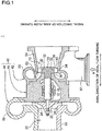
- FIG. 1 is a schematic cross-sectional view of a turbocharger according to one embodiment of the present invention.
- a turbocharger 1 illustrated in FIG. 1 is not particularly limited and only needs to be a supercharger for forcedly sending intake air into an internal combustion engine.
- the turbocharger may be a turbocharger for an automobile, or a turbocharger for a ship.
- the turbocharger 1 includes an axial flow turbine 10 and a compressor 20 driven by the axial flow turbine 10.
- the axial flow turbine 10 is configured to be driven by exhaust gas from an internal combustion engine (not illustrated).
- the compressor 20 is configured to be driven by the axial flow turbine 10 to compress intake air flowing into the internal combustion engine.
- the axial flow turbine 10 includes a rotation shaft 12 extending in the axial direction and a turbine wheel 14 which is rotatable together with the rotation shaft 12. In this way, when energy of the exhaust gas from the internal combustion engine serving as high-temperature and high-pressure working fluid is recovered by the turbine wheel 14, the turbine wheel 14 and the rotation shaft 12 rotate together.
- the rotation shaft 12 of the axial flow turbine 10 is rotatably supported to a housing 40 by a bearing 16. Further, the rotation shaft 12 is coupled to a compressor wheel 22 of a compressor 20 at the opposite side from the axial flow turbine 10 across the bearing 16 in the axial direction.
- the turbine wheel 14 includes a plurality of turbine blades (turbine impeller) 30.
- Each turbine blade 30 extends outwardly in the radial direction of the axial flow turbine 10 from a hub 32 toward a tip 34. Further, between the hub 32 and the tip 34, the turbine blade 30 has an airfoil formed by a concave surface (pressure surface) and a convex surface (suction surface).
- the concave surface and the convex surface forming the airfoil are connected to each other at the upstream side in the axial direction to form a leading edge 36, and connected to each other at the downstream side in the axial direction to form a trailing edge 38.
- the rotation shaft 12 and the turbine wheel 14 formed as separate members are coupled to each other, so that the rotation shaft 12 and the turbine wheel 14 rotate together.
- the rotation shaft 12 and the turbine wheel 14 are formed as a single peace, and thereby the rotation shaft 12 and the turbine wheel 14 rotate together.
- the turbine wheel 14 is covered by a housing 40.
- the housing 40 is configured to be dividable into the following three sections: a turbine housing 42, a bearing housing 44, and a compressor housing 46.
- the turbine housing 42 is disposed so as to cover mainly the turbine wheel 14.
- the bearing housing 44 is disposed so as to cover mainly the bearing 16.
- the compressor housing 46 is disposed so as to cover mainly the compressor wheel 22.
- the positions of the dividing lines between the sections (42, 44, 46) of the housing 40 are not particularly limited, and are set suitably in view of the assembly performance of the turbocharger 1. Further, the number of divided sections of the housing 40 is not limited to three, and the housing 40 may be dividable into a certain number other than three (e.g. four or more) of divided sections.
- the housing 40 (in the embodiment illustrated in FIG. 1 , the turbine housing 42) includes a scroll part 50 for introducing exhaust gas into the housing 40 and a bend part 52 for directing the exhaust gas from the scroll part 50 to the turbine blades 30.
- the scroll part 50 is configured to swirl the exhaust gas flowing in from an exhaust-gas inlet 51 (see arrow a) in the circumferential direction of the rotation shaft 12.
- the swirl flow of the exhaust gas flows out from the scroll part 50 inwardly in the radial direction of the axial flow turbine 10.
- the exhaust gas having flowed out from the scroll part 50 is directed toward the turbine blades 30 by the bend part 52.
- the direction of the flow of the exhaust gas flowing inwardly in the radial direction from the scroll part 50 is changed into a direction along the axial direction of the axial flow turbine 10 by the bend part 52.
- the exhaust gas whose flow direction has been accordingly changed by the bend part 52 acts on the turbine blades 30 and rotates the turbine wheel 14.
- the exhaust gas having performed work on the turbine wheel 14 is discharged from a gas outlet 54 disposed on the housing 40 (in the embodiment illustrated in FIG. 1 , the turbine housing 42).
- the rotation shaft 12 of the axial flow turbine 10 is coupled to the compressor wheel 22 of the compressor 20 at the opposite side from the axial flow turbine 10 across the bearing 16, as described above.
- the torque from the turbine wheel 14 is inputted into the compressor wheel 22 via the rotation shaft 12.
- the compressor wheel 22 also rotates together with the turbine wheel 14.
- the housing 40 (in the embodiment illustrated in FIG. 1 , the compressor housing 46) includes an air inlet 58 for introducing air into the housing 40.
- the air from the air inlet 58 is directed to a plurality of impellers 24 of the rotating compressor wheel 22, and is compressed when passing through the impellers 24.
- the air compressed by the compressor wheel 22 (compressed air) is discharged from a compressed-air outlet (scroll) 56 disposed on the housing 40 (in the embodiment illustrated in FIG. 1 , the compressor housing 46), and then sent into the internal combustion engine.
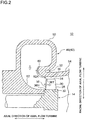
- FIG. 2 is a schematic cross-sectional view of the axial flow turbine 10 according to one embodiment.
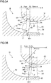
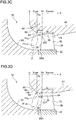
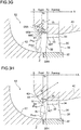
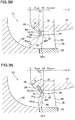
- FIGs. 3A to 3O are each a schematic cross-sectional view of a bend part of the axial flow turbine 10 according to one embodiment, and the peripheral structure thereof.
- x-axis is a coordinate parallel to the axial direction of the axial flow turbine 10
- the bend part 52 includes a tip-side inner wall surface 60 having a bend shape, at least in a region 52A at the upstream side, in the axial direction, of a portion 36H of the leading edge 36 of the turbine blade 30, the portion 36H being adjacent to the hub 32.
- the tip-side inner wall surface 60 having a bend shape, of the bend part 52 is present at least in the region 52A at the upstream side, in the axial direction, of the portion 36H of the turbine blade 30.
- the tip-side inner wall surface 60 having a bend shape may be disposed entirely over the region 52A, or partially in the region 52A. Further, the tip-side inner wall surface 60 having a bend shape may extend from the region 52A toward the downstream side, and terminate at a downstream position, in the axial direction, of the portion 36H of the turbine blade 30.
- the tip-side inner wall surface 60 described here is a portion of the inner wall surface of the bend part 52 forming a part of a path of working fluid in the axial flow turbine 10, the portion being adjacent to the tip 34 disposed at the outer side in the radial direction of the turbine.
- a portion adjacent to the hub 32 disposed at the inner side in the radial direction of the turbine is a hub-side inner wall surface 62 that faces the tip-side inner wall surface 60.
- the tip-side inner wall surface 60 is a convex surface as a whole
- the hub-side inner wall surface 62 is a concave surface as a whole.
- the tip-side inner wall surface 60 may be partially formed by a concave surface
- the hub-side inner wall surface 62 may be partially formed by a convex surface.
- the bend shape along the axial direction of the turbine of the tip-side inner wall surface 60 has a maximum curvature section 64 defined by the minimum curvature radius R min at the position X Z , and a portion 66 defined by a curvature radius R at the upstream side, in the axial direction, of the position X Z , as illustrated in FIGs. 3A to 3O .
- the curvature radius R is greater than the minimum curvature radius R min of the maximum curvature section 64 (i.e., R > R min ).
- W is a turbine-blade tip width, which is a width in the axial direction of the turbine (direction X) of the turbine blade 30 at the tip 34.
- the position X 0 is a position, in the axial direction, of the leading edge 36 at the tip 34 (i.e., of the leading edge 36, the position, in the axial direction, of a portion 36T at the tip side).
- a pressure distribution (pressure gradient) is formed from the tip side to the hub side by the centrifugal force due to the minimum curvature radius R min of the maximum curvature section 64.
- the centrifugal force due to the minimum curvature radius R min reduces the pressure P Tip of the working fluid at the tip side of the region Z, while the pressure P Hub of the working fluid increases at the hub side of the region Z.
- the velocity of the working fluid increases in accordance with the pressure decrease.
- the turning angle of the flow of the working fluid acting on the tip side of the turbine blade 30 is small.
- the pressure differential between the concave side and the convex side of the turbine blade 30 at the tip side decreases with a decrease in the turning angle of the flow, which suppresses leakage of the working fluid via a tip clearance 35 and improves turbine efficiency.
- the tip clearance 35 is a gap formed between the tip 34 and the inner wall surface of the housing 40.
- the tip-leakage suppression effect due to the centrifugal force of the minimum curvature radius R min of the bend part 52 can be achieved if the position of the minimum curvature radius R min is in the vicinity of the leading edge of the turbine blade, and the position X Z in the axial direction of the minimum curvature radius R min may be either at the upstream side or at the downstream side of the portion 36T of the turbine blade 30.
- the maximum curvature section 64 defined by the minimum curvature radius R min at the position X Z in the axial direction is in the range of X upst ⁇ X Z ⁇ X 0 , which is an upstream side of the portion 36T of the turbine blade 30.
- the maximum curvature section 64 defined by the minimum curvature radius R min at the position X Z in the axial direction is in the range of X 0 ⁇ X Z ⁇ X downst , which is a downstream side of the portion 36T of the turbine blade 30.
- the position X Z in the axial direction of the maximum curvature section 64 is set within a range of X 0 - 0.35W ⁇ X 0 ⁇ X 0 + 0.35W.
- the maximum curvature section 64 is positioned in a range close to the leading edge of the turbine blade, which further improves the tip-leakage suppression effect achieved by the centrifugal force due to the minimum curvature radius R min .
- the tip 34 faces the inner wall surface of the housing 40 not via a seal member.
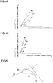
- FIG. 4A is a diagram illustrating a velocity triangle at the tip side in the region Z in the embodiment where the bend part 52 has the maximum curvature section 64 at the position X Z in the axial direction in the vicinity of the leading edge of the turbine blade, and a portion 66 at the upstream side in the axial direction of the position X Z .
- FIG. 4B is a velocity triangle at the tip side of the region Z in a comparison example where the curvature radius of the tip-side inner wall surface of the bend part is constant regardless of the position in the axial direction.
- FIG. 5 is a diagram for describing a turning angle of a flow of working fluid according to one embodiment.
- the velocity component v X in the axial direction of the absolute velocity vector V acting on the turbine blade 30 increases as compared to the comparison example.
- the velocity component v C in the circumferential direction of the absolute velocity vector V is basically given to the working fluid by the scroll part 50 and does not depend on the shape of the bend part 52.
- an angle (inflow angle) A formed between the axial direction of the turbine and a relative velocity vector V* obtained by subtracting the tip-speed vector Vr of the turbine blade 30 from the absolute velocity vector V is small.
- the turning angle B (see FIG. 5 ) of the flow of the working fluid acting on the side of the tip 34 of the turbine blade 30 is smaller than that in the comparison example, and thus leakage of the working fluid via the tip clearance 35 is suppressed and the turbine efficiency is improved.
- the bend shape of the tip-side inner wall surface 60 includes a discontinuous point at which the first linear section 68 at the upstream side of the position X Z in the axial direction intersects with the second linear section 69 at the downstream side of the position X Z in the axial direction.
- This discontinuous point forms the maximum curvature section 64 defined by the minimum curvature radius R min .
- the minimum curvature radius R min is substantially zero (i.e. zero or a value close to zero).
- the portion 66 defined by a curvature radius R (> R min ) at the upstream side in the axial direction of the position X Z is formed by the first linear section 68.
- the curvature radius R is substantially infinite.
- the position X Z in the axial direction at which the minimum curvature radius R min is actually formed is determined precisely without being affected by the machining accuracy of the bend part 52, which makes it possible to achieve the desired tip-leakage suppression effect securely by the minimum curvature radius R min at the position X Z .
- the bend shape of the tip-side inner wall surface 60 has two or more curvature radii including the minimum curvature radius R min at least in the positional range of 0 ⁇ X ⁇ X Z in the axial direction.
- the two or more curvature radii are arranged in a descending order of curvature radius from the upstream side toward the downstream side in the axial direction in the positional range of 0 ⁇ X ⁇ X Z in the axial direction.
- the curvature radius of the bend shape gradually reduces from the upstream side toward the downstream side, and reaches its minimum (the minimum curvature radius R min ) at the position X Z in the axial direction at the most downstream side.
- the working fluid having a pressure gradient of the region Z formed by a great centrifugal force due to the minimum curvature radius R min at the position X Z in the axial direction to act directly on the turbine blade 30.
- a part of the tip-side inner wall surface 60 of the bend part 52 is formed by a projecting portion 70 disposed on the position X Z in the axial direction.
- the projecting portion 70 is disposed so as to protrude inwardly in the radial direction of the axial flow turbine 10 from the other part of the tip-side inner wall surface 60.
- the maximum curvature section 64 defined by the minimum curvature radius R min is disposed on a tip end (projection end) of the projecting portion 70.
- the projecting portion 70 is formed as a separate member from the other part of the tip-side inner wall surface 60.
- the projecting portion 70 includes an annular plate portion 72 extending inwardly in the radial direction from the other part of the tip-side inner wall surface 60, and an edge on a tip end (projection end) of the annular plate portion 72 forms the maximum curvature section 64.
- the annular plate portion 72 may be disposed parallel to the radial direction of the axial flow turbine 10 as illustrated in FIGs. 3L and 3M , or may be disposed so as to be inclined from the radial direction of the axial flow turbine as illustrated in FIG. 3N .
- the projection end of the projecting portion 70 having the minimum curvature radius R min is disposed on the outer side of the tip 34 of the turbine blade 30 in the radial direction of the axial flow turbine 10.
- the projection end of the projecting portion 70 having the minimum curvature radius R min is disposed on the inner side of the tip 34 of the turbine blade 30 in the radial direction of the axial flow turbine 10.
- the housing 40 may be dividable into the first section 40A including the projecting portion 70 and the second section 40B positioned at the downstream side of the first section 40A.
- the projecting portion 70 is disposed on the upstream side, in the axial direction, of the tip 34 of the turbine blade 30 and the projection end of the projecting portion 70 is disposed on the inner side of the tip 34 in the radial direction, it is possible to assemble the axial flow turbine 10 easily.
- the tip surface of the turbine blade 30 is inclined from the axial direction of the axial flow turbine 10 so that the blade length of the turbine blade 30 gradually increases from the leading edge 36 toward the trailing edge 38.
- the inner wall surface of the housing 40 is inclined from the axial direction of the axial flow turbine 10 along the tip surface of the turbine blade 30.
- the housing 40 includes a protruding portion 74 protruding inwardly in the radial direction of the axial flow turbine 10 at a position, in the axial direction, corresponding to an outlet of the turbine wheel 14.
- the negative curvature radius refers to a curvature radius at which the inner wall surface of the housing 40 recesses outwardly in the radial direction of the axial flow turbine 10.
- the inner wall surface of the housing 40 has four negative curvature radii in the positional range of 0 ⁇ X ⁇ X F as indicated by arrows in the drawing.
- a pressure distribution (pressure gradient) is formed from the tip side to the hub side in the working fluid acting on the turbine blade 30 by adjusting the shape of the bend part 52, and at the tip side, the velocity of the working fluid (velocity component in the axial direction) increases with the pressure decrease.
- the turning angle of the flow of the working fluid decreases at the tip side and the pressure differential between the concave side and the convex side of the turbine blade 30 decreases, which suppresses leakage of the working fluid via the tip clearance 35.
- a small axial flow turbine it is especially advantageous for a small axial flow turbine to be able to suppress tip leakage by adjusting the shape of the bend part 52 as in the above embodiments, because, in a small axial flow turbine, the tip clearance tends to become large with respect to the blade length of the turbine blade.
- the axial flow turbine 10 for the turbocharger 1 is described in the above embodiment, the above description with respect to the axial flow turbine 10 can be applied to any axial flow turbine of radial inflow type for recovering power from energy of working fluid.
- the tip-side inner wall surface 60 of the bend part 52 of the described axial flow turbine 10 is at least in the region 52A at the upstream side, in the axial direction, of the portion 36H adjacent to the hub, of the leading edge 36 of the turbine blade 30.
- a technique similar to the present invention can be applied to a mixed flow turbine as well.
- FIG. 6 is a schematic cross-sectional view of a mixed flow turbine according to a reference example.
- the mixed flow turbine 100 includes a rotation shaft 112 extending in the axial direction, a turbine wheel 114 which is rotatable along with the rotation shaft 112, and a housing 140 covering the turbine wheel 114.
- the housing 140 includes a scroll part 150 for swirling working fluid that flows into the housing 140 along the circumferential direction of the rotation shaft 112. Further, the bend part 152 of the housing 140 is disposed between the scroll part 150 and the turbine wheel 114.
- the tip-side inner wall surface 160 of the bend part 152 does not extend to the upstream side, in the axial direction, of a portion 86H of the leading edge 86 of the turbine blade 80 adjacent to the hub 82, and is at the downstream side, in the axial direction, of the portion 86H.
- the mixed flow turbine 100 is different from the above described axial flow turbine 10.
- the bend shapes as in the embodiments illustrated in FIGs. 3A to 3O can be applied to the bend shape of the bend part 152 of the mixed flow turbine 100.
Landscapes
- Engineering & Computer Science (AREA)
- Mechanical Engineering (AREA)
- General Engineering & Computer Science (AREA)
- Chemical & Material Sciences (AREA)
- Combustion & Propulsion (AREA)
- Chemical Kinetics & Catalysis (AREA)
- General Chemical & Material Sciences (AREA)
- Supercharger (AREA)
Priority Applications (1)
| Application Number | Priority Date | Filing Date | Title |
|---|---|---|---|
| EP16194815.3A EP3159504B1 (de) | 2013-06-20 | 2013-06-20 | Axialturbine mit radialer anströmung und turbolader |
Applications Claiming Priority (3)
| Application Number | Priority Date | Filing Date | Title |
|---|---|---|---|
| EP16194815.3A EP3159504B1 (de) | 2013-06-20 | 2013-06-20 | Axialturbine mit radialer anströmung und turbolader |
| EP13887473.0A EP3012417B1 (de) | 2013-06-20 | 2013-06-20 | Axialturbine mit radialer anströmung und turbolader |
| PCT/JP2013/066963 WO2014203372A1 (ja) | 2013-06-20 | 2013-06-20 | 半径流入式軸流タービン及びターボチャージャ |
Related Parent Applications (2)
| Application Number | Title | Priority Date | Filing Date |
|---|---|---|---|
| EP13887473.0A Division-Into EP3012417B1 (de) | 2013-06-20 | 2013-06-20 | Axialturbine mit radialer anströmung und turbolader |
| EP13887473.0A Division EP3012417B1 (de) | 2013-06-20 | 2013-06-20 | Axialturbine mit radialer anströmung und turbolader |
Publications (2)
| Publication Number | Publication Date |
|---|---|
| EP3159504A1 true EP3159504A1 (de) | 2017-04-26 |
| EP3159504B1 EP3159504B1 (de) | 2021-03-03 |
Family
ID=52104134
Family Applications (2)
| Application Number | Title | Priority Date | Filing Date |
|---|---|---|---|
| EP13887473.0A Active EP3012417B1 (de) | 2013-06-20 | 2013-06-20 | Axialturbine mit radialer anströmung und turbolader |
| EP16194815.3A Not-in-force EP3159504B1 (de) | 2013-06-20 | 2013-06-20 | Axialturbine mit radialer anströmung und turbolader |
Family Applications Before (1)
| Application Number | Title | Priority Date | Filing Date |
|---|---|---|---|
| EP13887473.0A Active EP3012417B1 (de) | 2013-06-20 | 2013-06-20 | Axialturbine mit radialer anströmung und turbolader |
Country Status (5)
| Country | Link |
|---|---|
| US (1) | US9745859B2 (de) |
| EP (2) | EP3012417B1 (de) |
| JP (1) | JP6017033B2 (de) |
| CN (1) | CN105308272B (de) |
| WO (1) | WO2014203372A1 (de) |
Families Citing this family (10)
| Publication number | Priority date | Publication date | Assignee | Title |
|---|---|---|---|---|
| US9863275B2 (en) * | 2013-12-17 | 2018-01-09 | Honeywell International, Inc. | Turbine shroud contour exducer relief |
| JP6674913B2 (ja) * | 2017-01-16 | 2020-04-01 | 三菱重工業株式会社 | 半径流入式タービン、過給機及び過給機の組み立て方法 |
| EP3530957B1 (de) * | 2017-02-08 | 2021-05-12 | Mitsubishi Heavy Industries Engine & Turbocharger, Ltd. | Verdichter und turbolader |
| KR101984397B1 (ko) * | 2017-09-29 | 2019-05-30 | 두산중공업 주식회사 | 로터, 터빈 및 이를 포함하는 가스터빈 |
| JP6939682B2 (ja) | 2018-04-06 | 2021-09-22 | トヨタ自動車株式会社 | 内燃機関 |
| JP2019183716A (ja) * | 2018-04-06 | 2019-10-24 | トヨタ自動車株式会社 | 内燃機関 |
| CN110529272A (zh) * | 2019-09-25 | 2019-12-03 | 潍柴动力股份有限公司 | 一种涡轮增压器的控制方法及装置 |
| CN111622816A (zh) * | 2020-05-18 | 2020-09-04 | 一汽解放汽车有限公司 | 一种提高涡轮增压器涡轮机效率的密封结构及设计方法 |
| CN113217226B (zh) * | 2021-06-02 | 2022-08-02 | 中国航发湖南动力机械研究所 | 桨扇涡轮一体式发动机 |
| JP7643308B2 (ja) | 2021-11-25 | 2025-03-11 | 株式会社豊田自動織機 | 燃料電池用流体機械 |
Citations (4)
| Publication number | Priority date | Publication date | Assignee | Title |
|---|---|---|---|---|
| US4850820A (en) | 1988-05-17 | 1989-07-25 | Allied-Signal Inc. | Exhaust gas driven turbocharger |
| EP0491134A1 (de) * | 1990-12-18 | 1992-06-24 | Asea Brown Boveri Ag | Einlassgehäuse für Dampfturbine |
| JPH09144550A (ja) | 1995-11-24 | 1997-06-03 | Ishikawajima Harima Heavy Ind Co Ltd | 過給機用タービン |
| GB2469101A (en) * | 2009-04-02 | 2010-10-06 | Cummins Turbo Tech Ltd | Rotating machine with sealing arrangement |
Family Cites Families (8)
| Publication number | Priority date | Publication date | Assignee | Title |
|---|---|---|---|---|
| JPS5122978Y2 (de) * | 1972-03-31 | 1976-06-14 | ||
| DE2539711C3 (de) | 1975-09-06 | 1980-03-06 | Maschinenfabrik Augsburg-Nuernberg Ag, 8900 Augsburg | Spiralgehäuse für Strömungsmaschinen |
| JPS58564B2 (ja) | 1976-08-03 | 1983-01-07 | 三菱重工業株式会社 | 排気タ−ビン過給機 |
| DE3462169D1 (en) | 1983-06-29 | 1987-02-26 | Bbc Brown Boveri & Cie | Axial turbine for a turbo charger |
| DE3741286C2 (de) | 1987-09-04 | 1996-02-22 | Gutehoffnungshuette Man | Aufladeeinheit |
| JP2005240727A (ja) | 2004-02-27 | 2005-09-08 | Mitsubishi Heavy Ind Ltd | 衝動型軸流タービン |
| JP2010169047A (ja) | 2009-01-26 | 2010-08-05 | Toshiba Corp | 軸流タービン |
| US8453448B2 (en) | 2010-04-19 | 2013-06-04 | Honeywell International Inc. | Axial turbine |
-
2013
- 2013-06-20 CN CN201380077537.1A patent/CN105308272B/zh active Active
- 2013-06-20 JP JP2015522434A patent/JP6017033B2/ja not_active Expired - Fee Related
- 2013-06-20 WO PCT/JP2013/066963 patent/WO2014203372A1/ja not_active Ceased
- 2013-06-20 EP EP13887473.0A patent/EP3012417B1/de active Active
- 2013-06-20 US US14/890,833 patent/US9745859B2/en not_active Expired - Fee Related
- 2013-06-20 EP EP16194815.3A patent/EP3159504B1/de not_active Not-in-force
Patent Citations (4)
| Publication number | Priority date | Publication date | Assignee | Title |
|---|---|---|---|---|
| US4850820A (en) | 1988-05-17 | 1989-07-25 | Allied-Signal Inc. | Exhaust gas driven turbocharger |
| EP0491134A1 (de) * | 1990-12-18 | 1992-06-24 | Asea Brown Boveri Ag | Einlassgehäuse für Dampfturbine |
| JPH09144550A (ja) | 1995-11-24 | 1997-06-03 | Ishikawajima Harima Heavy Ind Co Ltd | 過給機用タービン |
| GB2469101A (en) * | 2009-04-02 | 2010-10-06 | Cummins Turbo Tech Ltd | Rotating machine with sealing arrangement |
Also Published As
| Publication number | Publication date |
|---|---|
| EP3012417A4 (de) | 2016-10-05 |
| CN105308272B (zh) | 2017-10-03 |
| EP3012417B1 (de) | 2017-11-01 |
| EP3012417A1 (de) | 2016-04-27 |
| CN105308272A (zh) | 2016-02-03 |
| EP3159504B1 (de) | 2021-03-03 |
| US20160160672A1 (en) | 2016-06-09 |
| JPWO2014203372A1 (ja) | 2017-02-23 |
| US9745859B2 (en) | 2017-08-29 |
| WO2014203372A1 (ja) | 2014-12-24 |
| JP6017033B2 (ja) | 2016-10-26 |
Similar Documents
| Publication | Publication Date | Title |
|---|---|---|
| US9745859B2 (en) | Radial-inflow type axial flow turbine and turbocharger | |
| JP6109197B2 (ja) | ラジアルタービン動翼 | |
| CN103906895B (zh) | 斜流式涡轮 | |
| US11378093B2 (en) | Throat distribution for a rotor and rotor blade having camber and location of local maximum thickness distribution | |
| US11181120B2 (en) | Throat distribution for a rotor and rotor blade having camber and location of local maximum thickness distribution | |
| US11280199B2 (en) | Throat distribution for a rotor and rotor blade having camber and location of local maximum thickness distribution | |
| CN109477417B (zh) | 涡轮增压器、涡轮增压器的喷嘴叶片以及涡轮机 | |
| JP5398515B2 (ja) | ラジアルタービンの動翼 | |
| US10982566B2 (en) | Turbine and gas turbine | |
| EP3919724B1 (de) | Charakteristische verteilung für das rotorblatt eines verstärkerrotors | |
| US11339680B2 (en) | Radial inflow turbine and turbocharger | |
| US11555500B2 (en) | Guide vane | |
| EP3686439B1 (de) | Mehrstufiger kreiselverdichter | |
| EP3680489A1 (de) | Verdichter für einen gasturbinenmotor umfassend einen diffusor mit schräge vorderkanten aufweisenden schaufeln | |
| US11835057B2 (en) | Impeller of centrifugal compressor, centrifugal compressor, and turbocharger |
Legal Events
| Date | Code | Title | Description |
|---|---|---|---|
| PUAI | Public reference made under article 153(3) epc to a published international application that has entered the european phase |
Free format text: ORIGINAL CODE: 0009012 |
|
| STAA | Information on the status of an ep patent application or granted ep patent |
Free format text: STATUS: REQUEST FOR EXAMINATION WAS MADE |
|
| 17P | Request for examination filed |
Effective date: 20161020 |
|
| AC | Divisional application: reference to earlier application |
Ref document number: 3012417 Country of ref document: EP Kind code of ref document: P |
|
| AK | Designated contracting states |
Kind code of ref document: A1 Designated state(s): AL AT BE BG CH CY CZ DE DK EE ES FI FR GB GR HR HU IE IS IT LI LT LU LV MC MK MT NL NO PL PT RO RS SE SI SK SM TR |
|
| STAA | Information on the status of an ep patent application or granted ep patent |
Free format text: STATUS: EXAMINATION IS IN PROGRESS |
|
| 17Q | First examination report despatched |
Effective date: 20200811 |
|
| GRAP | Despatch of communication of intention to grant a patent |
Free format text: ORIGINAL CODE: EPIDOSNIGR1 |
|
| STAA | Information on the status of an ep patent application or granted ep patent |
Free format text: STATUS: GRANT OF PATENT IS INTENDED |
|
| INTG | Intention to grant announced |
Effective date: 20201208 |
|
| GRAS | Grant fee paid |
Free format text: ORIGINAL CODE: EPIDOSNIGR3 |
|
| GRAA | (expected) grant |
Free format text: ORIGINAL CODE: 0009210 |
|
| STAA | Information on the status of an ep patent application or granted ep patent |
Free format text: STATUS: THE PATENT HAS BEEN GRANTED |
|
| AC | Divisional application: reference to earlier application |
Ref document number: 3012417 Country of ref document: EP Kind code of ref document: P |
|
| AK | Designated contracting states |
Kind code of ref document: B1 Designated state(s): AL AT BE BG CH CY CZ DE DK EE ES FI FR GB GR HR HU IE IS IT LI LT LU LV MC MK MT NL NO PL PT RO RS SE SI SK SM TR |
|
| REG | Reference to a national code |
Ref country code: GB Ref legal event code: FG4D |
|
| REG | Reference to a national code |
Ref country code: CH Ref legal event code: EP Ref country code: AT Ref legal event code: REF Ref document number: 1367427 Country of ref document: AT Kind code of ref document: T Effective date: 20210315 |
|
| REG | Reference to a national code |
Ref country code: DE Ref legal event code: R096 Ref document number: 602013076098 Country of ref document: DE |
|
| REG | Reference to a national code |
Ref country code: IE Ref legal event code: FG4D |
|
| REG | Reference to a national code |
Ref country code: NL Ref legal event code: FP |
|
| REG | Reference to a national code |
Ref country code: LT Ref legal event code: MG9D |
|
| PG25 | Lapsed in a contracting state [announced via postgrant information from national office to epo] |
Ref country code: HR Free format text: LAPSE BECAUSE OF FAILURE TO SUBMIT A TRANSLATION OF THE DESCRIPTION OR TO PAY THE FEE WITHIN THE PRESCRIBED TIME-LIMIT Effective date: 20210303 Ref country code: FI Free format text: LAPSE BECAUSE OF FAILURE TO SUBMIT A TRANSLATION OF THE DESCRIPTION OR TO PAY THE FEE WITHIN THE PRESCRIBED TIME-LIMIT Effective date: 20210303 Ref country code: GR Free format text: LAPSE BECAUSE OF FAILURE TO SUBMIT A TRANSLATION OF THE DESCRIPTION OR TO PAY THE FEE WITHIN THE PRESCRIBED TIME-LIMIT Effective date: 20210604 Ref country code: NO Free format text: LAPSE BECAUSE OF FAILURE TO SUBMIT A TRANSLATION OF THE DESCRIPTION OR TO PAY THE FEE WITHIN THE PRESCRIBED TIME-LIMIT Effective date: 20210603 Ref country code: LT Free format text: LAPSE BECAUSE OF FAILURE TO SUBMIT A TRANSLATION OF THE DESCRIPTION OR TO PAY THE FEE WITHIN THE PRESCRIBED TIME-LIMIT Effective date: 20210303 Ref country code: BG Free format text: LAPSE BECAUSE OF FAILURE TO SUBMIT A TRANSLATION OF THE DESCRIPTION OR TO PAY THE FEE WITHIN THE PRESCRIBED TIME-LIMIT Effective date: 20210603 |
|
| REG | Reference to a national code |
Ref country code: AT Ref legal event code: MK05 Ref document number: 1367427 Country of ref document: AT Kind code of ref document: T Effective date: 20210303 |
|
| PG25 | Lapsed in a contracting state [announced via postgrant information from national office to epo] |
Ref country code: RS Free format text: LAPSE BECAUSE OF FAILURE TO SUBMIT A TRANSLATION OF THE DESCRIPTION OR TO PAY THE FEE WITHIN THE PRESCRIBED TIME-LIMIT Effective date: 20210303 Ref country code: LV Free format text: LAPSE BECAUSE OF FAILURE TO SUBMIT A TRANSLATION OF THE DESCRIPTION OR TO PAY THE FEE WITHIN THE PRESCRIBED TIME-LIMIT Effective date: 20210303 Ref country code: PL Free format text: LAPSE BECAUSE OF FAILURE TO SUBMIT A TRANSLATION OF THE DESCRIPTION OR TO PAY THE FEE WITHIN THE PRESCRIBED TIME-LIMIT Effective date: 20210303 Ref country code: SE Free format text: LAPSE BECAUSE OF FAILURE TO SUBMIT A TRANSLATION OF THE DESCRIPTION OR TO PAY THE FEE WITHIN THE PRESCRIBED TIME-LIMIT Effective date: 20210303 |
|
| PG25 | Lapsed in a contracting state [announced via postgrant information from national office to epo] |
Ref country code: EE Free format text: LAPSE BECAUSE OF FAILURE TO SUBMIT A TRANSLATION OF THE DESCRIPTION OR TO PAY THE FEE WITHIN THE PRESCRIBED TIME-LIMIT Effective date: 20210303 Ref country code: CZ Free format text: LAPSE BECAUSE OF FAILURE TO SUBMIT A TRANSLATION OF THE DESCRIPTION OR TO PAY THE FEE WITHIN THE PRESCRIBED TIME-LIMIT Effective date: 20210303 Ref country code: SM Free format text: LAPSE BECAUSE OF FAILURE TO SUBMIT A TRANSLATION OF THE DESCRIPTION OR TO PAY THE FEE WITHIN THE PRESCRIBED TIME-LIMIT Effective date: 20210303 Ref country code: AT Free format text: LAPSE BECAUSE OF FAILURE TO SUBMIT A TRANSLATION OF THE DESCRIPTION OR TO PAY THE FEE WITHIN THE PRESCRIBED TIME-LIMIT Effective date: 20210303 |
|
| PG25 | Lapsed in a contracting state [announced via postgrant information from national office to epo] |
Ref country code: IS Free format text: LAPSE BECAUSE OF FAILURE TO SUBMIT A TRANSLATION OF THE DESCRIPTION OR TO PAY THE FEE WITHIN THE PRESCRIBED TIME-LIMIT Effective date: 20210703 Ref country code: PT Free format text: LAPSE BECAUSE OF FAILURE TO SUBMIT A TRANSLATION OF THE DESCRIPTION OR TO PAY THE FEE WITHIN THE PRESCRIBED TIME-LIMIT Effective date: 20210705 Ref country code: ES Free format text: LAPSE BECAUSE OF FAILURE TO SUBMIT A TRANSLATION OF THE DESCRIPTION OR TO PAY THE FEE WITHIN THE PRESCRIBED TIME-LIMIT Effective date: 20210303 Ref country code: SK Free format text: LAPSE BECAUSE OF FAILURE TO SUBMIT A TRANSLATION OF THE DESCRIPTION OR TO PAY THE FEE WITHIN THE PRESCRIBED TIME-LIMIT Effective date: 20210303 Ref country code: RO Free format text: LAPSE BECAUSE OF FAILURE TO SUBMIT A TRANSLATION OF THE DESCRIPTION OR TO PAY THE FEE WITHIN THE PRESCRIBED TIME-LIMIT Effective date: 20210303 |
|
| REG | Reference to a national code |
Ref country code: DE Ref legal event code: R097 Ref document number: 602013076098 Country of ref document: DE |
|
| PLBE | No opposition filed within time limit |
Free format text: ORIGINAL CODE: 0009261 |
|
| STAA | Information on the status of an ep patent application or granted ep patent |
Free format text: STATUS: NO OPPOSITION FILED WITHIN TIME LIMIT |
|
| PG25 | Lapsed in a contracting state [announced via postgrant information from national office to epo] |
Ref country code: DK Free format text: LAPSE BECAUSE OF FAILURE TO SUBMIT A TRANSLATION OF THE DESCRIPTION OR TO PAY THE FEE WITHIN THE PRESCRIBED TIME-LIMIT Effective date: 20210303 Ref country code: AL Free format text: LAPSE BECAUSE OF FAILURE TO SUBMIT A TRANSLATION OF THE DESCRIPTION OR TO PAY THE FEE WITHIN THE PRESCRIBED TIME-LIMIT Effective date: 20210303 Ref country code: MC Free format text: LAPSE BECAUSE OF FAILURE TO SUBMIT A TRANSLATION OF THE DESCRIPTION OR TO PAY THE FEE WITHIN THE PRESCRIBED TIME-LIMIT Effective date: 20210303 |
|
| REG | Reference to a national code |
Ref country code: CH Ref legal event code: PL |
|
| 26N | No opposition filed |
Effective date: 20211206 |
|
| PG25 | Lapsed in a contracting state [announced via postgrant information from national office to epo] |
Ref country code: SI Free format text: LAPSE BECAUSE OF FAILURE TO SUBMIT A TRANSLATION OF THE DESCRIPTION OR TO PAY THE FEE WITHIN THE PRESCRIBED TIME-LIMIT Effective date: 20210303 |
|
| REG | Reference to a national code |
Ref country code: BE Ref legal event code: MM Effective date: 20210630 |
|
| PG25 | Lapsed in a contracting state [announced via postgrant information from national office to epo] |
Ref country code: LU Free format text: LAPSE BECAUSE OF NON-PAYMENT OF DUE FEES Effective date: 20210620 |
|
| PG25 | Lapsed in a contracting state [announced via postgrant information from national office to epo] |
Ref country code: LI Free format text: LAPSE BECAUSE OF NON-PAYMENT OF DUE FEES Effective date: 20210630 Ref country code: IT Free format text: LAPSE BECAUSE OF FAILURE TO SUBMIT A TRANSLATION OF THE DESCRIPTION OR TO PAY THE FEE WITHIN THE PRESCRIBED TIME-LIMIT Effective date: 20210303 Ref country code: IE Free format text: LAPSE BECAUSE OF NON-PAYMENT OF DUE FEES Effective date: 20210620 Ref country code: CH Free format text: LAPSE BECAUSE OF NON-PAYMENT OF DUE FEES Effective date: 20210630 |
|
| PG25 | Lapsed in a contracting state [announced via postgrant information from national office to epo] |
Ref country code: IS Free format text: LAPSE BECAUSE OF FAILURE TO SUBMIT A TRANSLATION OF THE DESCRIPTION OR TO PAY THE FEE WITHIN THE PRESCRIBED TIME-LIMIT Effective date: 20210703 |
|
| PGFP | Annual fee paid to national office [announced via postgrant information from national office to epo] |
Ref country code: NL Payment date: 20220513 Year of fee payment: 10 |
|
| PG25 | Lapsed in a contracting state [announced via postgrant information from national office to epo] |
Ref country code: BE Free format text: LAPSE BECAUSE OF NON-PAYMENT OF DUE FEES Effective date: 20210630 |
|
| PGFP | Annual fee paid to national office [announced via postgrant information from national office to epo] |
Ref country code: GB Payment date: 20220428 Year of fee payment: 10 Ref country code: FR Payment date: 20220510 Year of fee payment: 10 |
|
| PG25 | Lapsed in a contracting state [announced via postgrant information from national office to epo] |
Ref country code: HU Free format text: LAPSE BECAUSE OF FAILURE TO SUBMIT A TRANSLATION OF THE DESCRIPTION OR TO PAY THE FEE WITHIN THE PRESCRIBED TIME-LIMIT; INVALID AB INITIO Effective date: 20130620 |
|
| PG25 | Lapsed in a contracting state [announced via postgrant information from national office to epo] |
Ref country code: CY Free format text: LAPSE BECAUSE OF FAILURE TO SUBMIT A TRANSLATION OF THE DESCRIPTION OR TO PAY THE FEE WITHIN THE PRESCRIBED TIME-LIMIT Effective date: 20210303 |
|
| PGFP | Annual fee paid to national office [announced via postgrant information from national office to epo] |
Ref country code: DE Payment date: 20230502 Year of fee payment: 11 |
|
| REG | Reference to a national code |
Ref country code: NL Ref legal event code: MM Effective date: 20230701 |
|
| GBPC | Gb: european patent ceased through non-payment of renewal fee |
Effective date: 20230620 |
|
| PG25 | Lapsed in a contracting state [announced via postgrant information from national office to epo] |
Ref country code: NL Free format text: LAPSE BECAUSE OF NON-PAYMENT OF DUE FEES Effective date: 20230701 |
|
| PG25 | Lapsed in a contracting state [announced via postgrant information from national office to epo] |
Ref country code: MK Free format text: LAPSE BECAUSE OF FAILURE TO SUBMIT A TRANSLATION OF THE DESCRIPTION OR TO PAY THE FEE WITHIN THE PRESCRIBED TIME-LIMIT Effective date: 20210303 Ref country code: GB Free format text: LAPSE BECAUSE OF NON-PAYMENT OF DUE FEES Effective date: 20230620 |
|
| PG25 | Lapsed in a contracting state [announced via postgrant information from national office to epo] |
Ref country code: FR Free format text: LAPSE BECAUSE OF NON-PAYMENT OF DUE FEES Effective date: 20230630 |
|
| PG25 | Lapsed in a contracting state [announced via postgrant information from national office to epo] |
Ref country code: MT Free format text: LAPSE BECAUSE OF FAILURE TO SUBMIT A TRANSLATION OF THE DESCRIPTION OR TO PAY THE FEE WITHIN THE PRESCRIBED TIME-LIMIT Effective date: 20210303 |
|
| REG | Reference to a national code |
Ref country code: DE Ref legal event code: R119 Ref document number: 602013076098 Country of ref document: DE |
|
| PG25 | Lapsed in a contracting state [announced via postgrant information from national office to epo] |
Ref country code: DE Free format text: LAPSE BECAUSE OF NON-PAYMENT OF DUE FEES Effective date: 20250101 |
|
| PG25 | Lapsed in a contracting state [announced via postgrant information from national office to epo] |
Ref country code: TR Free format text: LAPSE BECAUSE OF FAILURE TO SUBMIT A TRANSLATION OF THE DESCRIPTION OR TO PAY THE FEE WITHIN THE PRESCRIBED TIME-LIMIT Effective date: 20210303 |