EP3159558A1 - Palier lisse et son procédé de fabrication - Google Patents
Palier lisse et son procédé de fabrication Download PDFInfo
- Publication number
- EP3159558A1 EP3159558A1 EP16811388.4A EP16811388A EP3159558A1 EP 3159558 A1 EP3159558 A1 EP 3159558A1 EP 16811388 A EP16811388 A EP 16811388A EP 3159558 A1 EP3159558 A1 EP 3159558A1
- Authority
- EP
- European Patent Office
- Prior art keywords
- staking
- face
- recesses
- recess
- flange member
- Prior art date
- Legal status (The legal status is an assumption and is not a legal conclusion. Google has not performed a legal analysis and makes no representation as to the accuracy of the status listed.)
- Withdrawn
Links
Images


Classifications
-
- F—MECHANICAL ENGINEERING; LIGHTING; HEATING; WEAPONS; BLASTING
- F16—ENGINEERING ELEMENTS AND UNITS; GENERAL MEASURES FOR PRODUCING AND MAINTAINING EFFECTIVE FUNCTIONING OF MACHINES OR INSTALLATIONS; THERMAL INSULATION IN GENERAL
- F16C—SHAFTS; FLEXIBLE SHAFTS; ELEMENTS OR CRANKSHAFT MECHANISMS; ROTARY BODIES OTHER THAN GEARING ELEMENTS; BEARINGS
- F16C17/00—Sliding-contact bearings for exclusively rotary movement
- F16C17/10—Sliding-contact bearings for exclusively rotary movement for both radial and axial load
-
- F—MECHANICAL ENGINEERING; LIGHTING; HEATING; WEAPONS; BLASTING
- F16—ENGINEERING ELEMENTS AND UNITS; GENERAL MEASURES FOR PRODUCING AND MAINTAINING EFFECTIVE FUNCTIONING OF MACHINES OR INSTALLATIONS; THERMAL INSULATION IN GENERAL
- F16C—SHAFTS; FLEXIBLE SHAFTS; ELEMENTS OR CRANKSHAFT MECHANISMS; ROTARY BODIES OTHER THAN GEARING ELEMENTS; BEARINGS
- F16C33/00—Parts of bearings; Special methods for making bearings or parts thereof
- F16C33/02—Parts of sliding-contact bearings
- F16C33/04—Brasses; Bushes; Linings
- F16C33/046—Brasses; Bushes; Linings divided or split, e.g. half-bearings or rolled sleeves
-
- F—MECHANICAL ENGINEERING; LIGHTING; HEATING; WEAPONS; BLASTING
- F16—ENGINEERING ELEMENTS AND UNITS; GENERAL MEASURES FOR PRODUCING AND MAINTAINING EFFECTIVE FUNCTIONING OF MACHINES OR INSTALLATIONS; THERMAL INSULATION IN GENERAL
- F16C—SHAFTS; FLEXIBLE SHAFTS; ELEMENTS OR CRANKSHAFT MECHANISMS; ROTARY BODIES OTHER THAN GEARING ELEMENTS; BEARINGS
- F16C33/00—Parts of bearings; Special methods for making bearings or parts thereof
- F16C33/02—Parts of sliding-contact bearings
- F16C33/04—Brasses; Bushes; Linings
- F16C33/06—Sliding surface mainly made of metal
- F16C33/14—Special methods of manufacture; Running-in
-
- F—MECHANICAL ENGINEERING; LIGHTING; HEATING; WEAPONS; BLASTING
- F16—ENGINEERING ELEMENTS AND UNITS; GENERAL MEASURES FOR PRODUCING AND MAINTAINING EFFECTIVE FUNCTIONING OF MACHINES OR INSTALLATIONS; THERMAL INSULATION IN GENERAL
- F16C—SHAFTS; FLEXIBLE SHAFTS; ELEMENTS OR CRANKSHAFT MECHANISMS; ROTARY BODIES OTHER THAN GEARING ELEMENTS; BEARINGS
- F16C43/00—Assembling bearings
- F16C43/02—Assembling sliding-contact bearings
-
- F—MECHANICAL ENGINEERING; LIGHTING; HEATING; WEAPONS; BLASTING
- F16—ENGINEERING ELEMENTS AND UNITS; GENERAL MEASURES FOR PRODUCING AND MAINTAINING EFFECTIVE FUNCTIONING OF MACHINES OR INSTALLATIONS; THERMAL INSULATION IN GENERAL
- F16C—SHAFTS; FLEXIBLE SHAFTS; ELEMENTS OR CRANKSHAFT MECHANISMS; ROTARY BODIES OTHER THAN GEARING ELEMENTS; BEARINGS
- F16C9/00—Bearings for crankshafts or connecting-rods; Attachment of connecting-rods
- F16C9/02—Crankshaft bearings
-
- F—MECHANICAL ENGINEERING; LIGHTING; HEATING; WEAPONS; BLASTING
- F16—ENGINEERING ELEMENTS AND UNITS; GENERAL MEASURES FOR PRODUCING AND MAINTAINING EFFECTIVE FUNCTIONING OF MACHINES OR INSTALLATIONS; THERMAL INSULATION IN GENERAL
- F16C—SHAFTS; FLEXIBLE SHAFTS; ELEMENTS OR CRANKSHAFT MECHANISMS; ROTARY BODIES OTHER THAN GEARING ELEMENTS; BEARINGS
- F16C2240/00—Specified values or numerical ranges of parameters; Relations between them
- F16C2240/94—Volume
-
- F—MECHANICAL ENGINEERING; LIGHTING; HEATING; WEAPONS; BLASTING
- F16—ENGINEERING ELEMENTS AND UNITS; GENERAL MEASURES FOR PRODUCING AND MAINTAINING EFFECTIVE FUNCTIONING OF MACHINES OR INSTALLATIONS; THERMAL INSULATION IN GENERAL
- F16C—SHAFTS; FLEXIBLE SHAFTS; ELEMENTS OR CRANKSHAFT MECHANISMS; ROTARY BODIES OTHER THAN GEARING ELEMENTS; BEARINGS
- F16C2360/00—Engines or pumps
- F16C2360/22—Internal combustion engines
Definitions
- the present invention relates to a technique for achieving both ease of assembly and dimensional accuracy of a flanged bearing.
- Patent Document 1 describes a thrust bearing assembly having a main bearing (corresponding to the half bearing) and a thrust washer (corresponding to the flange).
- Patent Document 1 JP 2008-510107A
- the present invention provides a technique for achieving both ease of assembly and dimensional accuracy of a flanged bearing.
- the present invention provides a sliding bearing including: a half bearing member having an inner circumferential face that slides against an associated shaft, and a plurality of recesses provided in a first end face in an axial direction of the associated shaft; a first flange member having a plurality of projections provided at positions corresponding to the plurality of recesses provided in the first end face; and a plurality of staking marks formed in a periphery of each recess when each recess is staked in a state where each of the plurality of projections is fitted to a corresponding one of the plurality of recesses in the first end face to fix the first flange member to the half bearing member, wherein, regarding staking marks formed on both sides of at least one of the plurality of recesses, when viewed in a radial direction of the associated shaft, a volume of a deformed portion near a staking mark located outside in a circumferential direction is smaller than a volume of a deformed portion close to a staking mark
- an angle of a staking mark located outside in the circumferential direction may be smaller than an angle of a staking mark located inside.
- a distance between a staking mark located outside in the circumferential direction and a corresponding recess may be longer than a distance between a staking mark located inside and the recess.
- the plurality of staking marks may have the same depth when viewed in the axial direction.
- a depth of a staking mark located outside in the circumferential direction may be shallower than a depth of a staking mark located inside.
- the plurality of staking marks may have the same angle when viewed in the axial direction.
- This sliding bearing may further include: a plurality of recesses provided in a second end face of the half bearing member in the axial direction; a second flange member having a plurality of projections provided at positions corresponding to the plurality of recesses provided in the second end face; and a plurality of staking marks formed in a periphery of each recess when each recess is staked in a state where each of the plurality of projections is fitted to a corresponding one of the plurality of recesses in the second end face to fix the second flange member to the half bearing member, wherein, in each of the first end face and the second end face, regarding staking marks formed on both sides of at least one of the plurality of recesses, when viewed in the radial direction, a volume of a deformed portion close to a staking mark located outside in the circumferential direction may be smaller than a volume of a deformed portion close to a staking mark located inside.
- the present invention also provides a method for manufacturing a sliding bearing including: a process of preparing a half bearing member having an inner circumferential face that slides against an associated shaft, and a plurality of recesses provided in a first end face in an axial direction of the associated shaft; a process of preparing a first flange member having a plurality of projections provided at positions corresponding to the plurality of recesses provided in the first end face; a process of preparing two punches arranged with a spacing wider than a width of the recess; and a process of, in a state where each of the plurality of projections is fitted to a corresponding one of the plurality of recesses in the first end face, staking at least one of the plurality of recesses such that a volume of a deformed portion close to a staking mark located outside in a circumferential direction of the associated shaft is smaller than a volume of a deformed portion close to a staking mark located inside, and fixing the first flange member to
- FIG. 1 is a diagram showing exemplary bearing 10 according to an embodiment.
- Bearing 10 is a flange assembly (an example of a sliding bearing) for supporting crankshaft S in cylinder block B (an example of a housing) in an automobile engine, for example.
- Crankshaft S is a cylindrical shaft and rotates relative to bearing 10.
- Crankshaft S is an example of an associated shaft that is associated with bearing 10.
- Bearing 10 has half bearing member 11, flange member 12 (an example of a first flange member), and flange member 13 (an example of a second flange member).
- Half bearing member 11 has a semi-cylindrical shape obtained by halving a cylinder in the axial direction. An inner circumferential face of half bearing member 11 slides against an outer circumferential face of crankshaft S.
- Half bearing member 11 is a main bearing that receives a load perpendicular to the axial direction.
- Flange member 12 and flange member 13 extend in a radial direction of the shaft from ends of half bearing member 11 in the axial direction.
- Flange member 12 and flange member 13 are thrust bearings (thrust washers) for receiving a load (thrust load) in the axial direction via cylinder block B (housing).
- Bearing 10 supports half of the outer circumference of crankshaft S in a cross-section thereof perpendicular to the axial direction. That is to say, two bearings 10 are used at one portion to support the entire circumference of crankshaft S.
- two bearings namely bearing 10a and bearing 10b are used.
- bearing 10a and bearing 10b do not necessarily need to be used as a pair, and only one of them may be used.
- either bearing 10a or bearing 10b may not necessarily have a flange member, and the flange member may be provided in only one of the bearings, or at one end of both bearings.
- a later-described overlay layer may be provided in only one of bearing 10a and bearing 10b, or in both of them.
- a coordinate system is defined for ease of understanding of the following description.
- the axial direction of the associated shaft is a z direction
- a position in the circumferential direction and the radial direction of the shaft is expressed as a polar coordinate system (r, ⁇ ).
- ⁇ denotes a displacement angle from a reference plane (e.g. a horizontal plane)
- r denotes a distance from a reference point (e.g. the center of the associated shaft).
- Half bearing member 11 has a multi-layer structure in which a back metal, a lining layer, and an overlay layer (which are not shown in the diagram), are stacked in the radial direction of the associated shaft, for example.
- the back metal is a layer that gives half bearing member 11 mechanical strength.
- the back metal is made of steel, for example.
- the lining layer is a layer for improving bearing properties, e.g. frictional properties, seizure resistance, wear resistance, conformability, foreign particle embedding properties (robustness against foreign particle), corrosion resistance, and the like.
- the lining layer is made of a bearing alloy.
- crankshaft S is made of steel
- an alloy of materials other than steel such as an aluminum alloy
- an alloy using a metal other than aluminum as a base such as a copper alloy
- the overlay layer is formed with a resin coating or metal plating as a coating layer for improving the properties of the lining layer, such as a friction coefficient, conformability, corrosion resistance, foreign particle embedding properties (robustness against foreign particle), and the like.
- Flange member 12 and flange member 13 are made of a material similar to that of half bearing member 11. However, flange member 12 and flange member 13 are manufactured separately from half bearing member 11, and are thereafter fixed to half bearing member 11. Therefore, flange member 12 and flange member 13 may be made of a material different from that of half bearing member 11, or may be formed to have a different thickness.
- end face 111 is a face whose normal line is oriented in the +z-axial direction.
- Half bearing member 11 also has an end face (an example of a second end face) on the side opposite to end face 111 (a portion that is hidden in FIG. 1 ), and recesses are also formed in this end face.
- each recesses 112 and three projections 122 are formed. Recess 112a and projection 122a, recess 112b and projection 122b, and recess 112c and projection 122c are respectively fitted to each other. Note that the width of each recess 112 is formed to be wider than the width of each projection 122.
- Flange member 12 is fixed to half bearing member 11 by staking regions close to each recess 112, in a state where each recess 112 is fitted to corresponding projection 122.
- "staking" refers to joining target parts by applying pressure thereto using a specific component.
- half bearing member 11 and flange member 12 are fixed to and integrated with each other when assembled to cylinder block B.
- bearing 10 By use of bearing 10 according to this embodiment, the man-hours for assembly to cylinder block B can be reduced, and the possibility of erroneous assembly with regard to the orientation of flange member 12 can also be reduced, compared with the case of assembling, to cylinder block B, half bearing member 11 and flange member 12 in a state that they are not fixed to each other.
- the fixation between flange member 13 and half bearing member 11 is similar to the fixation between flange member 12 and half bearing member 11.
- the fixation between half bearing member 11 and flange member 12 needs to be maintained at least only while bearing 10 is assembled to cylinder block B. After assembly, the fixation state may not necessarily be maintained when the engine is driven. The staking of flange member 12 may be released as a result of receiving a load in the axial direction. In this case, when the engine operates, flange member 12 moves in accordance with the load, comes into contact with cylinder block B, and receives a load.
- FIG. 2 is a flowchart of an exemplary method for manufacturing bearing 10 according to an embodiment.
- process S1 half bearing member 11 is prepared.
- FIG. 3 is a diagram showing an exemplary external appearance of half bearing member 11.
- a method for manufacturing half bearing member 11 is as follows, for example. Initially, the bearing alloy that is to serve as the lining layer is, for example, pressure-welded onto a plate-shaped back metal to obtain a bimetal. This plate-shaped base material is cut into short strips (small pieces) collectively having a size corresponding to half bearing member 11, and these strips are formed into a semi-cylindrical shape. Thereafter, portions corresponding to both end sides in the axial direction are cut off at a certain width. Thereafter, the recesses that pass through from the top to the bottom of half bearing member 11 are formed, and the overlay layer is formed over the bimetal according to the required properties. The height of these recess forming portions is lower than that of a sliding face of half bearing member 11.
- Half bearing member 11 has overlay layer 118 on a part of inner circumferential face 117.
- Overlay layer 118 extends in the circumferential direction of the associated shaft. Front faces at both ends of overlay layer 118 in the axial direction are machined, and the lining layer or the back metal is exposed.
- Recesses 112 and recesses 114 are formed in the part where the lining layer or the back metal is exposed.
- recesses 112 are formed in face 111 that is one end face of half bearing member 11 in the axial direction, and pass through from inner circumferential face 117 to outer circumferential face 119. The same applies to recesses 114. Note that recesses 112 and recesses 114 may not pass through up to inner circumferential face 117.
- FIG. 4 is an external view of half bearing member 11 when viewed in the axial direction.
- Recess 112b is formed in a central part of the inner circumference of half bearing member 11.
- Recess 112a is formed on the - ⁇ side when viewed from recess 112b, and recess 112c is formed on the + ⁇ side when viewed from recess 112b.
- the distance from recess 112b to recess 112a is equal to the distance from recess 112b to recess 112c.
- Half bearing member 11 has parting line 115 and parting line 116 that come into contact with another bearing 10.
- distance rmi from midpoint Cm to the sliding face is referred to as an "inner radius”
- distance rmo to the outer circumferential face (back face) is referred to as an "outer radius.”
- the outer radius is not strictly uniform.
- Outer diameter dmo on the parting lines is larger than imaginary outer diameter 2rmo of the central part. That is to say, the outer circumferential face of half bearing member 11 is not a mathematically accurate arc. The same applies to the inner radius.
- outer diameter dmo is referred to as a "free spread.”
- free spread tensile force from the inside to the outside of half bearing member 11 is exerted on cylinder block B, and the effect of suppressing bearing 10 being detached from cylinder block B is obtained.
- the amount of free spread is designed in accordance with the dimensions of the bearing.
- flange member 12 and flange member 13 are prepared.
- flange member 12 will be described, since flange member 12 and flange member 13 have an identical shape.
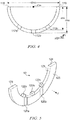
- FIG. 5 is a diagram showing an exemplary external appearance of flange member 12.
- a method for manufacturing flange member 12 is as follows, for example. Initially, a plate-shaped bimetal is formed, similar to half bearing member 11. A shape corresponding to flange member 12 is cut out from this plate-shaped base material. Furthermore, an overlay layer is formed according to the required properties, if necessary.
- Flange member 12 has thrust face 125 for receiving a thrust load, and inner circumferential face 121 that comes into contact with half bearing member 11.
- Lubrication grooves 126 are formed in thrust face 125.
- two lubrication grooves namely lubrication groove 126a and lubrication groove 126b are formed.
- Lubrication grooves 126 are grooves for holding lubricating oil and also serving as an oil supply route for receiving a supply of the lubricating oil from half bearing member 11.
- Projections 122 are formed in inner circumferential face 121.
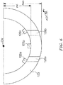
- FIG. 6 is an external view of flange member 12 when viewed in the axial direction.
- Projection 122b is formed in a central part of the inner circumference of flange member 12.
- Projection 122a is formed on the - ⁇ side when viewed from projection 122b, and projection 122c is formed on the + ⁇ side when viewed from projection 122b.
- the distance from projection 122b to projection 122a is equal to the distance from projection 122b to projection 122c.
- Projections 122a to 122c are formed at positions such that they can be fitted to recesses 112a to 112c in half bearing member 11.
- Flange member 12 has parting line 123 and parting line 124 that correspond respectively to parting line 115 and parting line 116 of half bearing member 11.
- midpoint Cw of a line connecting parting line 123 and parting line 124 to be an imaginary central point distance rwi from midpoint Cw to the inner circumferential face is referred to as an "inner radius,” and distance rwo to the outer circumferential face is referred to as an "outer radius.”
- the inner radius of flange member 12 is substantially equal to the outer radius of half bearing member 11.
- process S3 a punch (tool) to be used for staking is prepared.
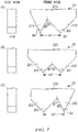
- FIG. 7 shows exemplary punches used in this embodiment.
- three punches namely, punch 21, punch 22, and punch 23 are used.
- Punch 21 is used for staking recess 112a and projection 122a.
- Punch 22 is used for staking recess 112b and projection 122b.
- Punch 23 is used for staking recess 112c and projection 122c.
- FIG. 7 shows these punches when viewed in a direction corresponding to the radial direction when in use (front view) and when viewed in the circumferential direction (side views).
- Punch 22 has punching portion 221 and punching portion 222.
- Punching portion 221 and punching portion 222 are machining tools for subjecting an object (a region close to each recess 112 in half bearing member 11) to plastic deformation. Tips of punching portion 221 and punching portion 222 have a pointed shape when viewed in the radial direction (i.e. from midpoint Cw or the axial center).
- the angles of inner faces of punching portions 221 and 222 relative to the moving direction of the punching portions (a downward direction in the diagram) when in use are both ⁇ 1.
- the angles of tips of punching portion 221 and punching portion 222 are the same, i.e. ⁇ 3.
- Distance W1 between the tip of punching portion 211 and the tip of punching portion 212 is wider than the width of each recess 112. With punch 22, both sides of each recess 112 can be staked with the same force.
- Punch 21 has punching portion 211 and punching portion 212.
- the angle of an inner face of punching portion 212 relative to the moving direction of the punching portion when in use is ⁇ 1, and the angle of an inner face of the punching portion 211 is ⁇ 2 (here, ⁇ 2 ⁇ 1).
- the angle of a tip of punching portion 212 is ⁇ 3, which is the same as angle ⁇ 3 of the tips of punching portion 221 and punching portion 222.
- the angle of a tip of punching portion 211 is ⁇ 4 (here, ⁇ 4 ⁇ 3).
- Punch 23 has punching portion 231 and punching portion 232.
- the angle of an inner face of punching portion 231 relative to the moving direction of the punching portion when in use is ⁇ 1, and the angle of an inner face of the punching portion 232 is ⁇ 2.
- the angle of a tip of punching portion 231 is ⁇ 3, which is the same as angle ⁇ 3 of the tips of punching portion 221 and punching portion 222.
- the angle of a tip of punching portion 232 is ⁇ 4, which is the same as the angle of the tip of punching portion 211.
- process S4 recesses 112 in half bearing member 11 and projections 122 in flange member 12 are fitted to each other. In process S5, regions close to each recess 112 in half bearing member 11 are staked.
- FIG. 8 schematically shows a process of plastic deformation of half bearing member 11 caused by the staking.
- Punch 21 moves in the axial direction of the associated shaft, and is positioned on face 111 of half bearing member 11 on one end side.
- punching portion 211 is positioned on the outside (the side closer to the parting line) of recess 121a in the circumferential direction
- punching portion 212 is positioned on the inside (the side closer to the central part) in the circumferential direction.
- FIG. 8(A) shows a state where punch 21 is in contact with face 111. Since half bearing member 11 and flange member 12 are fitted to each other, projection 122a is present within recess 112a.
- punch 21 After punch 21 has been pushed in by a given amount, the staking is complete ( FIG. 8(C) ).
- Punch 21 is moved in the opposite direction and is removed.
- staking mark 1111 and staking mark 1112 are formed on the respective sides of recess 112a.
- the angles of the bottom of the staking marks correspond to the shape of punch 21.
- the angle of staking mark 1111 is smaller (corresponding to ⁇ 4), and the angle of staking mark 1112 is larger (corresponding to ⁇ 3).
- the volume of a deformed portion of a wall face of recess 112a obtained as a result of the staking using punching portion 211 is smaller than the volume of the deformed portion of a wall face of recess 112a obtained as a result of the staking using punching portion 212 (a right wall face in the diagram). That is to say, the force of the deformed wall face pressing recess 122a (staking force) is relatively smaller on the outside in the circumferential direction, and is larger on the inside in the circumferential direction.
- FIG. 9 is an enlarged view of staking mark 1111 and staking mark 1112.
- projection 122a is omitted.
- the deformed portions of the wall faces of recess 112a will now be described.
- portions (hatched in FIG. 9 ) of recess 112a on the inside of imaginary lines (corresponding to the wall faces of recess 112a before the staking) extending in the axial direction from the bottom of recess 112a can be regarded as the deformed portions obtained as a result of the staking.
- Recess 112b and recess 112c are staked using punch 22 and punch 23, respectively.
- the staking at two outermost positions in the circumferential direction of a total of six staking positions at the three recesses can be performed more weakly than at the other positions.
- the depths of the staking marks formed on both sides of each single recess 112 are substantially equal.
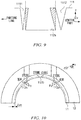
- FIG. 10 shows a staking force distribution in bearing 10.
- the staking force at the two outermost points is smaller than at the other four points, and the four points closer to the central part are staked with a relatively larger staking force, as already described. If these six points are staked with the same force, F0 in the radial direction of bearing 10, i.e. force that reduces the free spread of half bearing member 11 is exerted by, in particular, the staking at the two outermost points. Due to this force, there is a concern that the dimensions of the free spread will become smaller than the designed values thereof. However, in this embodiment, the two outermost points are staked with a relatively small force. Therefore, force F0 is smaller than in the case of staking the six points with the same force, and a reduction in the free spread can be suppressed.
- positions for staking recesses 112 are positions separate from the inner circumferential face of half bearing member 11 in the radial direction by margin ⁇ m. This is for preventing the influence of the deformation due to the staking from being exerted on the sliding face.
- bearing 10 is finished. According to this embodiment, a bearing that achieves both ease of assembly to a housing and dimensional accuracy can be obtained.
- the inventors of the present application performed experiments to verify the effects of the invention of the present application. The method and the results of the experiment will be described below.
- FIG. 11 shows experimental conditions.
- two samples shown in experimental examples 1 to 3 were used in the experiment.
- Bearings having an inner diameter of 64 mm were used as the samples.
- the bearings used in the experiment have three recesses in one flange. That is to say, six points were staked in one flange.
- an offset of 0.5 mm was provided in the distances to the tips of a punch to be used for staking an outermost recess, thereby making the staking force at the two outermost points smaller than at the other four points.
- the angles of both punching portions were 60°.
- six points were equally staked.
- the angles of both punching portions were 60°.
- the staking force at the two outermost points were made smaller than at the other four points using the method described in the embodiment.
- the angles of the respective punching portions were 60° and 45°.
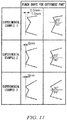
- FIG. 12 is a diagram showing external appearances of the staking marks at the outermost recess obtained in experimental examples 1 to 3.
- FIG. 12 is a diagram schematically showing the external appearances of the staking marks when viewed in the radial direction.
- the inclination (deformation) of the inner wall of the recess was smaller than on the center side.
- the inner wall of the recess largely inclined to fix projection 122, whereas, on the parting line side, the inner wall of the recess inclined to such a degree that it slightly touched projection 122.
- the inner walls of the recess inclined on both the parting line side and the center side that is to say, it is conceivable that, compared with experimental example 1, the capability to hold the flange improved in experimental examples 2 and 3.
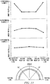
- FIG. 13 is a diagram showing results of measurement of the inner width between the flanges in experimental examples 1 to 3.
- FIG. 13 shows the results of measuring the inner width between the flanges (in the example in the embodiment, the distance from the back face of flange member 12 (the back face of the thrust face) to the back face of flange member 13) while changing positions, i.e. at positions in regions close to the parting lines, a position in the central part, and positions in parts therebetween (at around 50°), for example.
- experimental example 1 there was a tendency that the inner width was wider in the regions close to the parting lines than in the central part.
- experimental example 2 there was a tendency that the inner width was wider in the regions close to the parting lines than in the central part.
- experimental example 3 there was a tendency that the difference in the inner width between the central part and the respective regions close to the parting lines was smaller than in experimental examples 1 and 2.
- experimental examples 1 and 3 have the effect of suppressing a dimensional change compared with experimental example 2.
- FIG. 8 shows an example in which each projection 122 is in contact with the bottom face of corresponding recess 112, a gap may be present between projection 122 and the bottom face of recess 112.
- the cross-sectional shape of projections 122 is not limited to the rectangle shown as an example in FIG. 8 . Other shapes, such as a shape formed by chamfering corners of a rectangle or an arch shape, may be used.
- FIG. 14 shows other exemplary staking methods.
- the method for staking recesses 112 is not limited to the method described in the embodiment.
- a punch having punching portions whose tip angles are the same, i.e. ⁇ 3, is used.
- an offset from an end of recess 112a is different between the outside (parting line side) and the inside (center side). Specifically, the outer offset is larger, and the inner offset is smaller.
- the larger offset side is affected by not only the wall face of recess 112a but also the plastic deformation of face 111. However, the amount of deformation of the wall face of recess 112a is smaller; i.e., the staking force is smaller, than with the other staking methods.
- FIG. 14(B) shows an example of the punch used in above experimental example 1.
- the distance to the tips of punching portions when the punch is in use the distance to the tip of the punching portion 211 is shorter, and the distance to the tip of punching portion 212 is longer (the difference therebetween is ⁇ h).
- ⁇ h the difference therebetween
- angles of the tips of the punching portions may be made different.
- the shape and the number of the recesses in half bearing member 11, and the shape and the number of the projections in flange member 12 are not limited to those described in the embodiment. Furthermore, the recesses and the projections may not be arranged at equal intervals. The same applies to flange member 13.
- bearing 10 is not limited to that described in the embodiment.
- both side portions on the front face may not be machined, and overlay layer 118 may be formed over the whole face.
- Half bearing member 11 may have a pawl for positioning, in a region close to either one of the parting lines.
- flange member 12 and flange member 13 may have a projecting detent for preventing relative rotation with respect to cylinder block B, in their outer circumferential faces.
- the shape and the number of lubrication grooves 126 are not limited to those described in the embodiment either.
- the flange members (flange member 12 and flange member 13) are fixed to respective ends in the axial direction.
- a flange member may be fixed to only one end.
- bearings 10 are used for supporting one portion of the associated shaft.
- the two bearings used here may have inner circumferential faces (sliding faces) of different shapes, for example.
- a lubrication groove or a lubrication hole may be provided in one of the upper and lower sliding faces.
- the usage of bearing 10 is not limited to supporting of crankshaft S.
Landscapes
- Engineering & Computer Science (AREA)
- General Engineering & Computer Science (AREA)
- Mechanical Engineering (AREA)
- Shafts, Cranks, Connecting Bars, And Related Bearings (AREA)
- Sliding-Contact Bearings (AREA)
Applications Claiming Priority (2)
| Application Number | Priority Date | Filing Date | Title |
|---|---|---|---|
| JP2015123786 | 2015-06-19 | ||
| PCT/JP2016/065307 WO2016203913A1 (fr) | 2015-06-19 | 2016-05-24 | Palier lisse et son procédé de fabrication |
Publications (2)
| Publication Number | Publication Date |
|---|---|
| EP3159558A1 true EP3159558A1 (fr) | 2017-04-26 |
| EP3159558A4 EP3159558A4 (fr) | 2017-10-11 |
Family
ID=57545532
Family Applications (1)
| Application Number | Title | Priority Date | Filing Date |
|---|---|---|---|
| EP16811388.4A Withdrawn EP3159558A4 (fr) | 2015-06-19 | 2016-05-24 | Palier lisse et son procédé de fabrication |
Country Status (5)
| Country | Link |
|---|---|
| US (1) | US9879718B2 (fr) |
| EP (1) | EP3159558A4 (fr) |
| JP (1) | JP6205508B2 (fr) |
| CN (1) | CN107110203B (fr) |
| WO (1) | WO2016203913A1 (fr) |
Families Citing this family (4)
| Publication number | Priority date | Publication date | Assignee | Title |
|---|---|---|---|---|
| US11644064B2 (en) * | 2017-02-24 | 2023-05-09 | Vibracoustic Se | Bearing bush |
| JP2019108908A (ja) * | 2017-12-15 | 2019-07-04 | 株式会社ジェイテクト | 転がり軸受の取付構造 |
| USD1006829S1 (en) * | 2019-08-07 | 2023-12-05 | Transportation Ip Holdings, Llc | Bearing apparatus |
| CN116116989A (zh) * | 2021-11-12 | 2023-05-16 | 苏州品翔电通有限公司 | 一种铆接模具及铆接方法 |
Family Cites Families (17)
| Publication number | Priority date | Publication date | Assignee | Title |
|---|---|---|---|---|
| GB1386253A (en) * | 1972-05-24 | 1975-03-05 | Vandervell Products Ltd | Flanged half bearings |
| US3972576A (en) * | 1975-02-27 | 1976-08-03 | Vandervell Products Limited | Flanged half bearings |
| GB8827606D0 (en) * | 1988-11-25 | 1988-12-29 | Vandervell Ltd | Bearings |
| GB9004716D0 (en) * | 1990-03-02 | 1990-04-25 | Glacier Metal Co Ltd | Bearings |
| DE4015156A1 (de) * | 1990-05-11 | 1991-11-14 | Bayer Ag | Verfahren zur herstellung von formkoerpern oder folien |
| DE4015256A1 (de) * | 1990-05-12 | 1991-11-14 | Glyco Metall Werke | Kombiniertes radial-axial-gleitlager |
| GB9127191D0 (en) * | 1991-12-21 | 1992-02-19 | T & N Technology Ltd | Flanged bearings |
| DE19825116A1 (de) * | 1998-06-05 | 1999-12-09 | Ks Gleitlager Gmbh | Gebaute Bundlagerschale |
| US20030128902A1 (en) * | 2002-01-10 | 2003-07-10 | Detroit Diesel Corporation | Snap together thrust and journal bearing assembly |
| US7134793B2 (en) | 2004-08-11 | 2006-11-14 | Federal-Mogul Worldwide, Inc. | Thrust bearing assembly |
| DE102009015370A1 (de) * | 2009-03-27 | 2010-10-28 | Ks Gleitlager Gmbh | Gebaute Bundlagerschale mit halbschalenförmigem Radiallagerteil und mit wenigstens einem scheibenförmigen Axiallagerteil |
| BRPI1100941A2 (pt) * | 2011-03-25 | 2013-06-11 | Mahle Metal Leve Sa | bronzina flangeada |
| CN202012563U (zh) * | 2011-05-11 | 2011-10-19 | 宁波市汽车轴瓦厂 | 整体铆合式浮动镶边瓦 |
| JP2014122660A (ja) | 2012-12-20 | 2014-07-03 | Taiho Kogyo Co Ltd | 軸受装置 |
| CN203114897U (zh) * | 2013-03-08 | 2013-08-07 | 山西新环橡塑制品有限公司 | 一种汽车滑动轴承 |
| JP6097209B2 (ja) | 2013-12-06 | 2017-03-15 | 大豊工業株式会社 | 軸受部材 |
| JP6110332B2 (ja) | 2014-04-09 | 2017-04-05 | 大豊工業株式会社 | 軸受部材 |
-
2016
- 2016-05-24 US US15/326,267 patent/US9879718B2/en not_active Expired - Fee Related
- 2016-05-24 EP EP16811388.4A patent/EP3159558A4/fr not_active Withdrawn
- 2016-05-24 JP JP2016561405A patent/JP6205508B2/ja not_active Expired - Fee Related
- 2016-05-24 CN CN201680003456.0A patent/CN107110203B/zh not_active Expired - Fee Related
- 2016-05-24 WO PCT/JP2016/065307 patent/WO2016203913A1/fr not_active Ceased
Also Published As
| Publication number | Publication date |
|---|---|
| CN107110203A (zh) | 2017-08-29 |
| JP6205508B2 (ja) | 2017-09-27 |
| WO2016203913A1 (fr) | 2016-12-22 |
| JPWO2016203913A1 (ja) | 2017-06-29 |
| US9879718B2 (en) | 2018-01-30 |
| CN107110203B (zh) | 2019-01-15 |
| EP3159558A4 (fr) | 2017-10-11 |
| US20170219008A1 (en) | 2017-08-03 |
Similar Documents
| Publication | Publication Date | Title |
|---|---|---|
| US9879718B2 (en) | Sliding bearing and method for manufacturing sliding bearing | |
| US9771980B2 (en) | Rolling bearing retainer and method for manufacturing such retainer | |
| JP4746155B1 (ja) | 半割すべり軸受の製造方法および半割すべり軸受 | |
| CN112739923A (zh) | 滚珠轴承用保持架及滚动轴承 | |
| US9194427B2 (en) | Bearing device | |
| US9863466B2 (en) | Sliding bearing | |
| JP5912413B2 (ja) | 固体潤滑剤埋込型軸受およびその製造方法 | |
| US20020122610A1 (en) | Dynamic pressure-type thrust bearing unit and manufacturing method thereof | |
| US10060472B2 (en) | Bearing device and method for manufacturing bearing device | |
| KR20140132012A (ko) | 경사판 | |
| EP3263931B1 (fr) | Palier lisse et procédé de fabrication de celui-ci | |
| JP7082475B2 (ja) | 滑り軸受 | |
| CN106795918A (zh) | 轴承装置和轴承装置的制造方法 | |
| US9587674B2 (en) | Sliding bearing | |
| JP6244367B2 (ja) | 軸受シェル | |
| JP2016191433A (ja) | 滑り軸受および滑り軸受の製造方法 | |
| CN219911512U (zh) | 圆锥滚子轴承 | |
| JP2015183797A (ja) | 軸受 | |
| JP2007303563A (ja) | 転がり軸受 |
Legal Events
| Date | Code | Title | Description |
|---|---|---|---|
| STAA | Information on the status of an ep patent application or granted ep patent |
Free format text: STATUS: THE INTERNATIONAL PUBLICATION HAS BEEN MADE |
|
| PUAI | Public reference made under article 153(3) epc to a published international application that has entered the european phase |
Free format text: ORIGINAL CODE: 0009012 |
|
| STAA | Information on the status of an ep patent application or granted ep patent |
Free format text: STATUS: REQUEST FOR EXAMINATION WAS MADE |
|
| 17P | Request for examination filed |
Effective date: 20170117 |
|
| AK | Designated contracting states |
Kind code of ref document: A1 Designated state(s): AL AT BE BG CH CY CZ DE DK EE ES FI FR GB GR HR HU IE IS IT LI LT LU LV MC MK MT NL NO PL PT RO RS SE SI SK SM TR |
|
| AX | Request for extension of the european patent |
Extension state: BA ME |
|
| A4 | Supplementary search report drawn up and despatched |
Effective date: 20170911 |
|
| RIC1 | Information provided on ipc code assigned before grant |
Ipc: F16C 17/10 20060101AFI20170905BHEP Ipc: F16C 33/14 20060101ALN20170905BHEP Ipc: F16C 9/02 20060101ALI20170905BHEP Ipc: F16C 43/02 20060101ALI20170905BHEP Ipc: F16C 33/08 20060101ALN20170905BHEP |
|
| DAV | Request for validation of the european patent (deleted) | ||
| DAX | Request for extension of the european patent (deleted) | ||
| RIC1 | Information provided on ipc code assigned before grant |
Ipc: F16C 17/10 20060101AFI20190329BHEP Ipc: F16C 33/08 20060101ALN20190329BHEP Ipc: F16C 43/02 20060101ALI20190329BHEP Ipc: F16C 9/02 20060101ALI20190329BHEP Ipc: F16C 33/14 20060101ALN20190329BHEP |
|
| RIC1 | Information provided on ipc code assigned before grant |
Ipc: F16C 43/02 20060101ALI20190510BHEP Ipc: F16C 17/10 20060101AFI20190510BHEP Ipc: F16C 33/14 20060101ALN20190510BHEP Ipc: F16C 9/02 20060101ALI20190510BHEP Ipc: F16C 33/08 20060101ALN20190510BHEP |
|
| GRAP | Despatch of communication of intention to grant a patent |
Free format text: ORIGINAL CODE: EPIDOSNIGR1 |
|
| RIC1 | Information provided on ipc code assigned before grant |
Ipc: F16C 33/14 20060101ALN20190612BHEP Ipc: F16C 17/10 20060101AFI20190612BHEP Ipc: F16C 43/02 20060101ALI20190612BHEP Ipc: F16C 33/08 20060101ALN20190612BHEP Ipc: F16C 9/02 20060101ALI20190612BHEP |
|
| STAA | Information on the status of an ep patent application or granted ep patent |
Free format text: STATUS: GRANT OF PATENT IS INTENDED |
|
| INTG | Intention to grant announced |
Effective date: 20190718 |
|
| STAA | Information on the status of an ep patent application or granted ep patent |
Free format text: STATUS: THE APPLICATION IS DEEMED TO BE WITHDRAWN |
|
| 18D | Application deemed to be withdrawn |
Effective date: 20191129 |