EP3164648B1 - Refroidissement de fluide frigorigène pour variateur de vitesse - Google Patents
Refroidissement de fluide frigorigène pour variateur de vitesse Download PDFInfo
- Publication number
- EP3164648B1 EP3164648B1 EP14896917.3A EP14896917A EP3164648B1 EP 3164648 B1 EP3164648 B1 EP 3164648B1 EP 14896917 A EP14896917 A EP 14896917A EP 3164648 B1 EP3164648 B1 EP 3164648B1
- Authority
- EP
- European Patent Office
- Prior art keywords
- temperature
- heat exchanger
- refrigerant
- pressure
- downstream
- Prior art date
- Legal status (The legal status is an assumption and is not a legal conclusion. Google has not performed a legal analysis and makes no representation as to the accuracy of the status listed.)
- Active
Links
Images

Classifications
-
- F—MECHANICAL ENGINEERING; LIGHTING; HEATING; WEAPONS; BLASTING
- F25—REFRIGERATION OR COOLING; COMBINED HEATING AND REFRIGERATION SYSTEMS; HEAT PUMP SYSTEMS; MANUFACTURE OR STORAGE OF ICE; LIQUEFACTION SOLIDIFICATION OF GASES
- F25B—REFRIGERATION MACHINES, PLANTS OR SYSTEMS; COMBINED HEATING AND REFRIGERATION SYSTEMS; HEAT PUMP SYSTEMS
- F25B1/00—Compression machines, plants or systems with non-reversible cycle
- F25B1/04—Compression machines, plants or systems with non-reversible cycle with compressor of rotary type
- F25B1/053—Compression machines, plants or systems with non-reversible cycle with compressor of rotary type of turbine type
-
- F—MECHANICAL ENGINEERING; LIGHTING; HEATING; WEAPONS; BLASTING
- F25—REFRIGERATION OR COOLING; COMBINED HEATING AND REFRIGERATION SYSTEMS; HEAT PUMP SYSTEMS; MANUFACTURE OR STORAGE OF ICE; LIQUEFACTION SOLIDIFICATION OF GASES
- F25B—REFRIGERATION MACHINES, PLANTS OR SYSTEMS; COMBINED HEATING AND REFRIGERATION SYSTEMS; HEAT PUMP SYSTEMS
- F25B1/00—Compression machines, plants or systems with non-reversible cycle
- F25B1/10—Compression machines, plants or systems with non-reversible cycle with multi-stage compression
-
- F—MECHANICAL ENGINEERING; LIGHTING; HEATING; WEAPONS; BLASTING
- F25—REFRIGERATION OR COOLING; COMBINED HEATING AND REFRIGERATION SYSTEMS; HEAT PUMP SYSTEMS; MANUFACTURE OR STORAGE OF ICE; LIQUEFACTION SOLIDIFICATION OF GASES
- F25B—REFRIGERATION MACHINES, PLANTS OR SYSTEMS; COMBINED HEATING AND REFRIGERATION SYSTEMS; HEAT PUMP SYSTEMS
- F25B31/00—Compressor arrangements
- F25B31/006—Cooling of compressor or motor
-
- F—MECHANICAL ENGINEERING; LIGHTING; HEATING; WEAPONS; BLASTING
- F25—REFRIGERATION OR COOLING; COMBINED HEATING AND REFRIGERATION SYSTEMS; HEAT PUMP SYSTEMS; MANUFACTURE OR STORAGE OF ICE; LIQUEFACTION SOLIDIFICATION OF GASES
- F25B—REFRIGERATION MACHINES, PLANTS OR SYSTEMS; COMBINED HEATING AND REFRIGERATION SYSTEMS; HEAT PUMP SYSTEMS
- F25B41/00—Fluid-circulation arrangements
- F25B41/30—Expansion means; Dispositions thereof
- F25B41/39—Dispositions with two or more expansion means arranged in series, i.e. multi-stage expansion, on a refrigerant line leading to the same evaporator
-
- F—MECHANICAL ENGINEERING; LIGHTING; HEATING; WEAPONS; BLASTING
- F25—REFRIGERATION OR COOLING; COMBINED HEATING AND REFRIGERATION SYSTEMS; HEAT PUMP SYSTEMS; MANUFACTURE OR STORAGE OF ICE; LIQUEFACTION SOLIDIFICATION OF GASES
- F25B—REFRIGERATION MACHINES, PLANTS OR SYSTEMS; COMBINED HEATING AND REFRIGERATION SYSTEMS; HEAT PUMP SYSTEMS
- F25B49/00—Arrangement or mounting of control or safety devices
- F25B49/02—Arrangement or mounting of control or safety devices for compression type machines, plants or systems
-
- F—MECHANICAL ENGINEERING; LIGHTING; HEATING; WEAPONS; BLASTING
- F25—REFRIGERATION OR COOLING; COMBINED HEATING AND REFRIGERATION SYSTEMS; HEAT PUMP SYSTEMS; MANUFACTURE OR STORAGE OF ICE; LIQUEFACTION SOLIDIFICATION OF GASES
- F25B—REFRIGERATION MACHINES, PLANTS OR SYSTEMS; COMBINED HEATING AND REFRIGERATION SYSTEMS; HEAT PUMP SYSTEMS
- F25B5/00—Compression machines, plants or systems, with several evaporator circuits, e.g. for varying refrigerating capacity
- F25B5/02—Compression machines, plants or systems, with several evaporator circuits, e.g. for varying refrigerating capacity arranged in parallel
-
- F—MECHANICAL ENGINEERING; LIGHTING; HEATING; WEAPONS; BLASTING
- F25—REFRIGERATION OR COOLING; COMBINED HEATING AND REFRIGERATION SYSTEMS; HEAT PUMP SYSTEMS; MANUFACTURE OR STORAGE OF ICE; LIQUEFACTION SOLIDIFICATION OF GASES
- F25B—REFRIGERATION MACHINES, PLANTS OR SYSTEMS; COMBINED HEATING AND REFRIGERATION SYSTEMS; HEAT PUMP SYSTEMS
- F25B2400/00—Component parts or details not otherwise provided for in this subclass
- F25B2400/05—Compression system with heat exchange between particular parts of the system
-
- F—MECHANICAL ENGINEERING; LIGHTING; HEATING; WEAPONS; BLASTING
- F25—REFRIGERATION OR COOLING; COMBINED HEATING AND REFRIGERATION SYSTEMS; HEAT PUMP SYSTEMS; MANUFACTURE OR STORAGE OF ICE; LIQUEFACTION SOLIDIFICATION OF GASES
- F25B—REFRIGERATION MACHINES, PLANTS OR SYSTEMS; COMBINED HEATING AND REFRIGERATION SYSTEMS; HEAT PUMP SYSTEMS
- F25B2600/00—Control issues
- F25B2600/02—Compressor control
- F25B2600/025—Compressor control by controlling speed
- F25B2600/0253—Compressor control by controlling speed with variable speed
-
- F—MECHANICAL ENGINEERING; LIGHTING; HEATING; WEAPONS; BLASTING
- F25—REFRIGERATION OR COOLING; COMBINED HEATING AND REFRIGERATION SYSTEMS; HEAT PUMP SYSTEMS; MANUFACTURE OR STORAGE OF ICE; LIQUEFACTION SOLIDIFICATION OF GASES
- F25B—REFRIGERATION MACHINES, PLANTS OR SYSTEMS; COMBINED HEATING AND REFRIGERATION SYSTEMS; HEAT PUMP SYSTEMS
- F25B2600/00—Control issues
- F25B2600/25—Control of valves
- F25B2600/2513—Expansion valves
-
- F—MECHANICAL ENGINEERING; LIGHTING; HEATING; WEAPONS; BLASTING
- F25—REFRIGERATION OR COOLING; COMBINED HEATING AND REFRIGERATION SYSTEMS; HEAT PUMP SYSTEMS; MANUFACTURE OR STORAGE OF ICE; LIQUEFACTION SOLIDIFICATION OF GASES
- F25B—REFRIGERATION MACHINES, PLANTS OR SYSTEMS; COMBINED HEATING AND REFRIGERATION SYSTEMS; HEAT PUMP SYSTEMS
- F25B2600/00—Control issues
- F25B2600/25—Control of valves
- F25B2600/2515—Flow valves
-
- F—MECHANICAL ENGINEERING; LIGHTING; HEATING; WEAPONS; BLASTING
- F25—REFRIGERATION OR COOLING; COMBINED HEATING AND REFRIGERATION SYSTEMS; HEAT PUMP SYSTEMS; MANUFACTURE OR STORAGE OF ICE; LIQUEFACTION SOLIDIFICATION OF GASES
- F25B—REFRIGERATION MACHINES, PLANTS OR SYSTEMS; COMBINED HEATING AND REFRIGERATION SYSTEMS; HEAT PUMP SYSTEMS
- F25B2700/00—Sensing or detecting of parameters; Sensors therefor
- F25B2700/19—Pressures
-
- F—MECHANICAL ENGINEERING; LIGHTING; HEATING; WEAPONS; BLASTING
- F25—REFRIGERATION OR COOLING; COMBINED HEATING AND REFRIGERATION SYSTEMS; HEAT PUMP SYSTEMS; MANUFACTURE OR STORAGE OF ICE; LIQUEFACTION SOLIDIFICATION OF GASES
- F25B—REFRIGERATION MACHINES, PLANTS OR SYSTEMS; COMBINED HEATING AND REFRIGERATION SYSTEMS; HEAT PUMP SYSTEMS
- F25B2700/00—Sensing or detecting of parameters; Sensors therefor
- F25B2700/21—Temperatures
- F25B2700/2115—Temperatures of a compressor or the drive means therefor
- F25B2700/21153—Temperatures of a compressor or the drive means therefor of electronic components
-
- F—MECHANICAL ENGINEERING; LIGHTING; HEATING; WEAPONS; BLASTING
- F25—REFRIGERATION OR COOLING; COMBINED HEATING AND REFRIGERATION SYSTEMS; HEAT PUMP SYSTEMS; MANUFACTURE OR STORAGE OF ICE; LIQUEFACTION SOLIDIFICATION OF GASES
- F25B—REFRIGERATION MACHINES, PLANTS OR SYSTEMS; COMBINED HEATING AND REFRIGERATION SYSTEMS; HEAT PUMP SYSTEMS
- F25B2700/00—Sensing or detecting of parameters; Sensors therefor
- F25B2700/21—Temperatures
- F25B2700/2117—Temperatures of an evaporator
- F25B2700/21175—Temperatures of an evaporator of the refrigerant at the outlet of the evaporator
-
- Y—GENERAL TAGGING OF NEW TECHNOLOGICAL DEVELOPMENTS; GENERAL TAGGING OF CROSS-SECTIONAL TECHNOLOGIES SPANNING OVER SEVERAL SECTIONS OF THE IPC; TECHNICAL SUBJECTS COVERED BY FORMER USPC CROSS-REFERENCE ART COLLECTIONS [XRACs] AND DIGESTS
- Y02—TECHNOLOGIES OR APPLICATIONS FOR MITIGATION OR ADAPTATION AGAINST CLIMATE CHANGE
- Y02B—CLIMATE CHANGE MITIGATION TECHNOLOGIES RELATED TO BUILDINGS, e.g. HOUSING, HOUSE APPLIANCES OR RELATED END-USER APPLICATIONS
- Y02B30/00—Energy efficient heating, ventilation or air conditioning [HVAC]
- Y02B30/70—Efficient control or regulation technologies, e.g. for control of refrigerant flow, motor or heating
Definitions
- Refrigerant compressors are used to circulate refrigerant to a chiller via a refrigerant loop.
- Prior refrigerant compressors have included impellers mounted on a shaft, which is driven by a motor at a fixed speed. These prior compressors have used mechanisms, such as inlet guide vanes and variable geometry diffusers, to adjust compressor capacity.
- VSD variable speed drive
- US2014013782 (A1 ) describes a system and method for controlling an economizer circuit is provided.
- the economizer circuit includes a valve to regulate refrigerant flow between the economizer and the compressor.
- US6434960 (B1 ) describes a compressor in a refrigeration system which is controlled solely by a variable speed drive which controls the motor of the compressor by virtue of the varying of the frequency of the electricity provided to the motor.
- WO2014082177 (A1 ) describes a cooling method and system, the system comprising a magnetic bearing centrifugal refrigeration compressor that uses liquid refrigerant from the condenser to supply cooling to its motor assembly; and a refrigerant pump installed in a motor cooling refrigerant supply line of the condenser.
- An example refrigerant system includes, among other things, a refrigerant loop having at least a condenser, an evaporator, and a compressor.
- the compressor includes a motor in communication with a variable speed drive.
- the system further includes a cooling circuit including a pressure regulator downstream of a heat exchanger, the heat exchanger absorbing heat from the variable speed drive.
- a temperature sensor is mounted to the variable speed drive.
- the temperature sensor is configured to produce an output indicative of the temperature of the variable speed drive.
- a controller is configured to receive the output from the temperature sensor, and to command an adjustment of the pressure regulator based on the output from the temperature sensor.
- the controller commands an adjustment of the pressure regulator when the output from the temperature sensor indicates that the temperature of the variable speed drive has deviated from a target temperature.
- the target temperature is predetermined.
- the cooling circuit includes an expansion valve upstream of the heat exchanger.
- a temperature sensor is downstream of the heat exchanger.
- the temperature sensor is configured to produce an output indicative of the temperature of the refrigerant within the cooling circuit at a location downstream of the heat exchanger.
- a pressure sensor is downstream of the heat exchanger. The pressure sensor is configured to produce an output indicative of the pressure of the refrigerant within the cooling circuit at a location downstream of the heat exchanger.
- a controller is configured to receive the outputs from the temperature and pressure sensors, and to command an adjustment of the expansion valve based on the outputs from the temperature and pressure sensors.
- the temperature and pressure sensors are positioned upstream of the pressure regulator.
- the temperature and pressure sensors are positioned downstream of the pressure regulator.
- the controller determines a level of superheat within the refrigerant downstream of the heat exchanger based on the outputs from the temperature and pressure sensors.
- the controller commands an adjustment of the expansion valve when the determined level of superheat deviates from a target superheat.
- the target superheat is predetermined.
- a source of refrigerant is provided to the cooling circuit from the condenser.
- refrigerant within the cooling circuit flows from the pressure regulator to the evaporator.
- a fan is configured to blow air onto the variable speed drive during operation of the compressor.
- a method for cooling a variable speed drive for a compressor includes, among other things, establishing a flow of refrigerant within a heat exchanger mounted to a variable speed drive, sensing a first temperature of the variable speed drive during operation of the compressor, and adjusting a pressure regulator downstream of the heat exchanger in response to the sensed first temperature.
- the pressure regulator is incrementally closed if the sensed first temperature is below a target temperature.
- a second temperature downstream of the heat exchanger is sensed, a pressure downstream of the heat exchanger is sensed, and an expansion valve upstream of the heat exchanger is adjusted in response to the sensed second temperature and the sensed pressure.
- the amount of superheat in the refrigerant downstream of the heat exchanger is determined based on the sensed second temperature and the sensed pressure, and the expansion valve is incrementally closed if the determined amount of superheat is below a target superheat amount.
- FIG. 1 schematically illustrates a refrigerant system 10.
- the system 10 includes a compressor 12 configured to pressurize a flow of refrigerant within a main refrigerant loop L.
- the compressor 12 in this example includes a first impeller 14 and a second impeller 16, each of which are mounted along a common shaft 18.
- the shaft 18 is driven by a motor 20.
- the motor 20 is in communication with a variable speed drive (VSD) 22.
- VSD variable speed drive
- VSDs are sometimes referred to as variable frequency drives.
- VSDs are known to include a main drive control assembly and a drive operator interface.
- the VSD 22 is configured to adjust a level of power delivered to the motor 20 and, thus vary the speed of rotation of the shaft 18.
- the main refrigerant loop L includes a condenser 24, an expansion valve 26 downstream of the condenser, and an evaporator 28 downstream of the expansion valve 26.
- the evaporator 28 is in fluid communication with the compressor 12.
- the refrigerant system 10 further includes a cooling circuit C for cooling the VSD 22.
- the cooling circuit C in one example, is provided with a source of refrigerant from the condenser 24. After cooling the VSD 22, the refrigerant flows downstream to the evaporator 28, where it is reintroduced into the main refrigerant loop L.
- the cooling circuit C could be sourced from any location between (1) the outlet of the compressor 12 and (2) any point upstream of the expansion valve 24. Additionally, the cooling circuit C could return refrigerant to the main refrigerant loop L at a location between (1) any point downstream of the expansion valve 26 and (2) an interstage port of the compressor 12 (i.e., a port between the first and second impellers 14, 16).
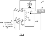
- the detail of one example cooling circuit C is illustrated in Figure 2 .
- the example cooling circuit C includes an expansion valve 30, a heat exchanger 32 downstream of the expansion valve 30, and a pressure regulator 34 downstream of the heat exchanger 32.
- the heat exchanger 32 is mounted to the VSD 22.
- the heat exchanger 32 may be a cold plate connected to a housing of the VSD 22.
- the VSD 22 may additionally be cooled by a fan 36, which is configured to blow relatively cool air on the VSD 22 during operation.
- the expansion valve 30 and the pressure regulator 34 may be any type of device configured to regulate a flow of refrigerant, including mechanical valves, such as butterfly, gate or ball valves with electrical or pneumatic control (e.g., valves regulated by existing pressures).
- the control of the expansion valve 30 and pressure regulator 34 is regulated by a controller 38, which may be any known type of controller including memory, hardware, and software.
- the controller 38 is configured to store instructions, and to provide those instructions to the various components of the cooling circuit C, as will be discussed below.
- refrigerant enters the cooling circuit C from the condenser 24.
- the fluid is relatively high temperature, and in a liquid state.
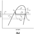
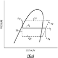
- the expansion valve 30 As fluid flows through the expansion valve 30, it becomes a mixture of vapor and liquid, at P 2 .
- the cooling circuit C provides an appropriate amount of refrigerant to the VSD 22 without forming condensation in the VSD 22. Condensation of water (i.e., water droplets) may form within the VSD 22 if the temperature of the VSD 22 falls below a certain temperature. This condensation may cause damage to the various electrical components within the VSD 22.
- the pressure regulator 34 is controlled to control the pressure of refrigerant within the heat exchanger 32, which in turn controls the temperature of that refrigerant, such that condensation does not form within the VSD 22.
- the expansion of refrigerant as it passes through the pressure regulator 34 is represented at P 3 in Figures 3-4 . Further, if an appropriate amount of refrigerant is provided to the heat exchanger 32 by the expansion valve 30, the refrigerant will absorb heat from the VSD 22 and be turned entirely into a vapor downstream of the heat exchanger 32, at point P 4 .
- the temperature of the VSD 22 is continually monitored by a first temperature sensor T 1 .
- the output of the first temperature sensor T 1 is reported to the controller 38.
- the controller 38 compares the output from the first temperature sensor T 1 to a target temperature T TARGET .
- the target temperature T TARGET is representative of a temperature at which there will be no (or extremely minimal) condensation within the VSD 22. That is, T TARGET is above a temperature at which condensation is known to begin to form.
- T TARGET is a predetermined value.
- the controller 38 is configured to determine T TARGET based on outside temperature and humidity.
- the controller 38 is further in communication with the pressure regulator 34, and is configured to command an adjustment of the pressure regulator 34 based on the output from the first temperature sensor T 1 .
- the position of the pressure regulator 34 controls the temperature of the refrigerant within the heat exchanger 32.
- the controller 38 maintains the position of the pressure regulator 34 such that the output from T 1 is equal to T TARGET .
- the controller 38 commands the pressure regulator 34 to incrementally close (e.g., by 5%). Conversely, if the output from T 1 increases, the controller 38 commands the pressure regulator 34 to incrementally open.
- Incrementally closing the pressure regulator 34 raises the temperature of the refrigerant within the heat exchanger 32, and prevents condensation from forming within the VSD 22.
- the controller 38 commands adjustment of the pressure regulator 34 until the output from T 1 returns to T TARGET .
- Closing the pressure regulator 34 raises the output from T 1 and raises the pressure P 2 , as illustrated graphically in Figure 3 at T 1' and P 2' .
- the controller 38 Concurrent with the control of the pressure regulator 34, the controller 38 also controls the expansion valve 30 during operation.
- the temperature and pressure of the refrigerant within the cooling circuit C downstream of the heat exchanger 32 are determined by a second temperature sensor T 2 and a pressure sensor P S .
- the temperature sensor T 2 and the pressure sensor P S are located downstream of the pressure regulator 34.
- T 2 and P S could be located downstream of the heat exchanger 32 and upstream of the pressure regulator 34.
- the outputs from the second temperature sensor T 2 and the pressure sensor P S are reported to the controller 38.
- the controller 38 is configured to determine (e.g., by using a look-up table) a level of superheat within the refrigerant downstream of the heat exchanger (e.g., at P 4 ).
- the controller 38 then compares the level of superheat within the refrigerant at P 4 and a superheat target value SH TARGET . This comparison indicates whether an appropriate level of fluid was provided to the heat exchanger 32 by the expansion valve 30.
- the output from the second temperature sensor T 2 is compared to a saturation temperature T SAT at the pressure sensor output from the pressure sensor P S . From this comparison, the controller 38 determines the level of superheat in the refrigerant. In one example, the controller 38 maintains the position of the expansion valve 30 such that the level of superheat exhibited by the refrigerant equals SH TARGET . If the level of superheat exhibited by the refrigerant falls below SH TARGET , the controller 38 will determine that too much fluid is provided to the heat exchanger 32 and will incrementally close the expansion valve 30. Conversely, the controller 38 will command the expansion valve 32 to incrementally open if the level of superheat exhibited by the refrigerant exceeds SH TARGET .
- sensor outputs are typically in the form of a change in some electrical signal (such as resistance or voltage), which is capable of being interpreted as a change in temperature or pressure, for example, by a controller (such as the controller 38).
- a controller such as the controller 38.
- the disclosure extends to all types of temperature and pressure sensors.
- the expansion valve 30 and pressure regulator 34 could be in communication with separate controllers. Additionally, the cooling circuit C does not require a dedicated controller 38. The functions of the controller 38 described above could be performed by a controller having additional functions. Further, the example control logic discussed above is exemplary. For instance, whereas in some instances this disclosure references the term "equal" in the context of comparisons to T TARGET and SH TARGET , the term “equal” is only used for purposes of illustration. In practice, there may be an acceptable (although relatively minor) variation in values that would still constitute "equal” for purposes of the control logic of this disclosure.
Landscapes
- Engineering & Computer Science (AREA)
- Physics & Mathematics (AREA)
- Mechanical Engineering (AREA)
- Thermal Sciences (AREA)
- General Engineering & Computer Science (AREA)
- Air Conditioning Control Device (AREA)
- Air-Conditioning For Vehicles (AREA)
Claims (14)
- Système de refroidissement (10), comprenant :une boucle de réfrigérant (L) incluant au moins un condenseur (24), un évaporateur (28), et un compresseur (12), le compresseur (12) incluant un moteur (20) en communication avec un entraînement à vitesse variable (22) ;un circuit de refroidissement (C) incluant un régulateur de pression (34) en aval d'un échangeur de chaleur (32), dans lequel l'échangeur de chaleur (32) est monté sur le variateur de vitesse (22) et l'échangeur de chaleur (32) absorbe la chaleur provenant de l'entraînement à vitesse variable (22) ;un capteur de température (T1) monté sur l'entraînement à vitesse variable (22), le capteur de température (T1) étant configuré pour produire un résultat indicatif de la température de l'entraînement à vitesse variable (22) ; etun système de commande (38) configuré pour recevoir le résultat du capteur de température (T1), et pour commander un ajustement du régulateur de pression (34), sur la base du résultat provenant du capteur de température (T1) ; dans lequelle système de commande (38) commande un ajustement du régulateur de pression (34) lorsque le résultat du capteur de température (T1) indique que la température de l'entraînement à vitesse variable (22) a dévié d'une température cible (TCIBLE).
- Système de refroidissement selon la revendication 1, dans lequel la température cible (TCIBLE) est prédéterminée.
- Système de refroidissement selon la revendication 1, dans lequel le circuit de refroidissement (C) inclut une soupape d'expansion (30) en amont de l'échangeur de chaleur (32).
- Système de refroidissement selon la revendication 3, comprenant en outre :un capteur de température (T2) en aval de l'échangeur de chaleur (32), le capteur de température (T2) étant configuré pour produire un résultat indicatif de la température du réfrigérant dans le circuit de refroidissement (C) en un emplacement en aval de l'échangeur de chaleur (32) ;un capteur de pression (Ps) en aval de l'échangeur de chaleur (32), le capteur de pression (Ps) étant configuré pour produire un résultat indicatif de la pression du réfrigérant dans le circuit de refroidissement (C) en un emplacement en aval de l'échangeur de chaleur (32) ; etun système de commande (38) configuré pour recevoir les résultats des capteurs de température (T2) et de pression (Ps), et pour commander un ajustement de la soupape d'expansion (30) sur la base des résultats des capteurs de température (T2) et de pression (Ps).
- Système de refroidissement selon la revendication 4, dans lequel les capteurs de température (T2) et de pression (Ps) sont positionnés en amont du régulateur de pression (34), ou dans lequel les capteurs de température (T2) et de pression (Ps) sont positionnés en aval du régulateur de pression (34).
- Système de refroidissement selon la revendication 4, dans lequel le système de commande (38) détermine un niveau de surchauffe dans le réfrigérant en aval de l'échangeur de chaleur (32) sur la base des résultats provenant des capteurs de température (T2) et de pression (Ps).
- Système de refroidissement selon la revendication 6, dans lequel le système de commande (38) commande un ajustement de la soupape d'expansion (30) lorsque le niveau déterminé de surchauffe dévie d'une surchauffe cible (SHCIBLE), et facultativement, dans lequel la surchauffe cible (SHCIBLE) est prédéterminée.
- Système de refroidissement selon la revendication 1, dans lequel une source de réfrigérant est fournie au circuit de refroidissement (C) depuis le condenseur (24).
- Système de refroidissement selon la revendication 1, dans lequel le réfrigérant dans le circuit de refroidissement (C) s'écoule du régulateur de pression (34) à l'évaporateur (28).
- Système de refroidissement selon la revendication 1, comprenant en outre :
un ventilateur (36) configuré pour souffler de l'air sur l'entraînement à vitesse variable (22) pendant le fonctionnement du compresseur (12). - Procédé de refroidissement d'un entraînement à vitesse variable (22) pour un compresseur (12), comprenant :l'établissement d'un flux de réfrigérant dans un échangeur de chaleur (32) monté sur un entraînement à vitesse variable (22) ;la détection d'une première température de l'entraînement à vitesse variable (22) pendant le fonctionnement du compresseur (12) ; etl'ajustement d'un régulateur de pression (34) en aval de l'échangeur de chaleur (32) en réponse à la première température détectée.
- Procédé selon la revendication 11, dans lequel le régulateur de pression (34) est fermé de manière incrémentielle si la première température détectée est inférieure à une température cible.
- Procédé selon la revendication 11, comprenant en outre :la détection d'une seconde température en aval de l'échangeur de chaleur (32) ;la détection d'une pression en aval de l'échangeur de chaleur (32) ; etl'ajustement d'une soupape d'expansion (30) en amont de l'échangeur de chaleur (32) en réponse à la seconde température détectée et à la pression détectée.
- Procédé selon la revendication 13, comprenant en outre :
la détermination de la quantité de surchauffe dans le réfrigérant en aval de l'échangeur de chaleur (32) sur la base de la seconde température détectée et de la pression détectée, dans lequel la soupape d'expansion (30) est fermée de manière incrémentielle si la quantité déterminée de surchauffe est inférieure à une quantité de surchauffe cible.
Applications Claiming Priority (1)
| Application Number | Priority Date | Filing Date | Title |
|---|---|---|---|
| PCT/US2014/045388 WO2016003467A1 (fr) | 2014-07-03 | 2014-07-03 | Refroidissement de fluide frigorigène pour variateur de vitesse |
Publications (3)
| Publication Number | Publication Date |
|---|---|
| EP3164648A1 EP3164648A1 (fr) | 2017-05-10 |
| EP3164648A4 EP3164648A4 (fr) | 2018-01-10 |
| EP3164648B1 true EP3164648B1 (fr) | 2020-12-09 |
Family
ID=55019809
Family Applications (1)
| Application Number | Title | Priority Date | Filing Date |
|---|---|---|---|
| EP14896917.3A Active EP3164648B1 (fr) | 2014-07-03 | 2014-07-03 | Refroidissement de fluide frigorigène pour variateur de vitesse |
Country Status (6)
| Country | Link |
|---|---|
| US (1) | US10830509B2 (fr) |
| EP (1) | EP3164648B1 (fr) |
| JP (1) | JP6681885B2 (fr) |
| KR (1) | KR102217500B1 (fr) |
| CN (1) | CN106662364A (fr) |
| WO (1) | WO2016003467A1 (fr) |
Families Citing this family (12)
| Publication number | Priority date | Publication date | Assignee | Title |
|---|---|---|---|---|
| IT201600080454A1 (it) * | 2016-08-01 | 2018-02-01 | Belimo Holding Ag | Dispositivo di controllo del surriscaldamento di un evaporatore di un circuito frigorifero |
| US11274679B2 (en) * | 2017-02-14 | 2022-03-15 | Danfoss A/S | Oil free centrifugal compressor for use in low capacity applications |
| CN107196462B (zh) * | 2017-07-17 | 2024-01-19 | 珠海格力电器股份有限公司 | 离心式冷水机组、中央空调及防凝露方法 |
| CN111133261B (zh) | 2017-09-25 | 2021-10-29 | 江森自控科技公司 | 变速驱动装置输入电流控制 |
| CN110081675B (zh) * | 2018-01-25 | 2023-11-24 | 郑州大学 | 一种新型冷冻干燥机冷热一体系统 |
| US11156231B2 (en) | 2018-03-23 | 2021-10-26 | Honeywell International Inc. | Multistage compressor having interstage refrigerant path split between first portion flowing to end of shaft and second portion following around thrust bearing disc |
| IT201800007390A1 (it) | 2018-07-20 | 2020-01-20 | Sistema di raffreddamento | |
| CN112805514A (zh) * | 2018-11-15 | 2021-05-14 | 李东源 | 改善了效率的热泵 |
| CN112484355B (zh) | 2019-09-12 | 2025-01-24 | 开利公司 | 空气调节系统及用于其的驱动电机冷却方法 |
| WO2021221806A1 (fr) | 2020-04-30 | 2021-11-04 | Danfoss A/S | Système et procédé de refroidissement de l'électronique de puissance de compresseurs frigorifiques |
| DE102020211295A1 (de) | 2020-09-09 | 2022-03-10 | Robert Bosch Gesellschaft mit beschränkter Haftung | Wärmepumpensystem und Verfahren zum Betrieb eines Wärmepumpensystems |
| EP4220034B1 (fr) | 2022-02-01 | 2025-11-05 | Thermo King LLC | Système de réfrigération ou pompe à chaleur et procédé de fonctionnement d'un système de réfrigération ou d'une pompe à chaleur |
Family Cites Families (22)
| Publication number | Priority date | Publication date | Assignee | Title |
|---|---|---|---|---|
| US5749237A (en) | 1993-09-28 | 1998-05-12 | Jdm, Ltd. | Refrigerant system flash gas suppressor with variable speed drive |
| JP3616152B2 (ja) | 1995-02-09 | 2005-02-02 | 松下電器産業株式会社 | 自動車用電動コンプレッサー駆動装置 |
| JPH09210518A (ja) * | 1996-02-06 | 1997-08-12 | Mitsubishi Heavy Ind Ltd | 冷凍装置 |
| JPH10160315A (ja) * | 1996-11-29 | 1998-06-19 | Sanyo Electric Co Ltd | 冷蔵庫 |
| US6434960B1 (en) * | 2001-07-02 | 2002-08-20 | Carrier Corporation | Variable speed drive chiller system |
| US6874329B2 (en) | 2003-05-30 | 2005-04-05 | Carrier Corporation | Refrigerant cooled variable frequency drive and method for using same |
| JP4687093B2 (ja) * | 2004-12-13 | 2011-05-25 | ダイキン工業株式会社 | 空気調和機 |
| US8418486B2 (en) * | 2005-04-08 | 2013-04-16 | Carrier Corporation | Refrigerant system with variable speed compressor and reheat function |
| US7628028B2 (en) | 2005-08-03 | 2009-12-08 | Bristol Compressors International, Inc. | System and method for compressor capacity modulation |
| US20080041081A1 (en) | 2006-08-15 | 2008-02-21 | Bristol Compressors, Inc. | System and method for compressor capacity modulation in a heat pump |
| US20070151269A1 (en) * | 2005-12-30 | 2007-07-05 | Johnson Controls Technology Company | System and method for level control in a flash tank |
| JP2010014340A (ja) * | 2008-07-03 | 2010-01-21 | Daikin Ind Ltd | 冷凍装置 |
| IT1395987B1 (it) * | 2009-10-16 | 2012-11-09 | Delphi Italia Automotive Systems S R L | Gruppo motore-compressore per un sistema di refrigerazione e/o condizionamento di un veicolo |
| WO2011077720A1 (fr) | 2009-12-22 | 2011-06-30 | ダイキン工業株式会社 | Dispositif de refrigeration |
| JP2011133133A (ja) * | 2009-12-22 | 2011-07-07 | Daikin Industries Ltd | 冷凍装置 |
| JP5370180B2 (ja) | 2010-01-26 | 2013-12-18 | 株式会社島津製作所 | X線分析用表示処理装置 |
| CN102844980B (zh) * | 2010-05-06 | 2016-01-20 | 大金工业株式会社 | 制冷装置 |
| CN103119382B (zh) * | 2010-09-14 | 2015-07-01 | 江森自控科技公司 | 用于控制节约器回路的系统和方法 |
| JP5353974B2 (ja) * | 2011-04-18 | 2013-11-27 | 株式会社日本自動車部品総合研究所 | 車両用電源装置 |
| US10184701B2 (en) * | 2011-09-16 | 2019-01-22 | Danfoss A/S | Motor cooling and sub-cooling circuits for compressor |
| US8950201B2 (en) | 2012-03-30 | 2015-02-10 | Trane International Inc. | System and method for cooling power electronics using heat sinks |
| WO2014082177A1 (fr) | 2012-11-29 | 2014-06-05 | Kiltech Inc. | Système et procédé de refroidissement de compresseurs à paliers magnétiques |
-
2014
- 2014-07-03 WO PCT/US2014/045388 patent/WO2016003467A1/fr not_active Ceased
- 2014-07-03 JP JP2017520864A patent/JP6681885B2/ja active Active
- 2014-07-03 CN CN201480080288.6A patent/CN106662364A/zh active Pending
- 2014-07-03 KR KR1020177002075A patent/KR102217500B1/ko active Active
- 2014-07-03 US US15/322,698 patent/US10830509B2/en active Active
- 2014-07-03 EP EP14896917.3A patent/EP3164648B1/fr active Active
Non-Patent Citations (1)
| Title |
|---|
| None * |
Also Published As
| Publication number | Publication date |
|---|---|
| JP2017522534A (ja) | 2017-08-10 |
| JP6681885B2 (ja) | 2020-04-15 |
| US20170131006A1 (en) | 2017-05-11 |
| EP3164648A1 (fr) | 2017-05-10 |
| US10830509B2 (en) | 2020-11-10 |
| EP3164648A4 (fr) | 2018-01-10 |
| KR20170024015A (ko) | 2017-03-06 |
| CN106662364A (zh) | 2017-05-10 |
| KR102217500B1 (ko) | 2021-02-19 |
| WO2016003467A1 (fr) | 2016-01-07 |
Similar Documents
| Publication | Publication Date | Title |
|---|---|---|
| EP3164648B1 (fr) | Refroidissement de fluide frigorigène pour variateur de vitesse | |
| KR101639174B1 (ko) | 공기 조화 장치 및 그 운전 방법 | |
| TWI557384B (zh) | 控制系統 | |
| US10215427B2 (en) | Air conditioning system and method for controlling air conditioning system | |
| US11137164B2 (en) | Control systems and methods for heat pump systems | |
| CN102741624B (zh) | 涡轮制冷机和制冷系统及其控制方法 | |
| JP6781034B2 (ja) | 冷媒回路システムおよび冷媒回路システムの制御方法 | |
| US10563673B2 (en) | Centrifugal compressor with liquid injection | |
| US10113553B2 (en) | Centrifugal compressor with hot gas injection | |
| TWI801460B (zh) | 暖通空調(hvac)系統、用於蒸氣壓縮系統之控制方法以及相關機器可讀媒體 | |
| JP2015161499A (ja) | ターボ冷凍機 | |
| WO2015126393A1 (fr) | Système et procédé de commande pour compresseur centrifuge | |
| JP2019184232A (ja) | 冷却装置 | |
| KR20180065314A (ko) | 터보 칠러 시스템 및 그 제어방법 | |
| WO2019017084A1 (fr) | Dispositif à cycle frigorifique |
Legal Events
| Date | Code | Title | Description |
|---|---|---|---|
| STAA | Information on the status of an ep patent application or granted ep patent |
Free format text: STATUS: THE INTERNATIONAL PUBLICATION HAS BEEN MADE |
|
| PUAI | Public reference made under article 153(3) epc to a published international application that has entered the european phase |
Free format text: ORIGINAL CODE: 0009012 |
|
| STAA | Information on the status of an ep patent application or granted ep patent |
Free format text: STATUS: REQUEST FOR EXAMINATION WAS MADE |
|
| 17P | Request for examination filed |
Effective date: 20161209 |
|
| AK | Designated contracting states |
Kind code of ref document: A1 Designated state(s): AL AT BE BG CH CY CZ DE DK EE ES FI FR GB GR HR HU IE IS IT LI LT LU LV MC MK MT NL NO PL PT RO RS SE SI SK SM TR |
|
| AX | Request for extension of the european patent |
Extension state: BA ME |
|
| DAX | Request for extension of the european patent (deleted) | ||
| REG | Reference to a national code |
Ref country code: DE Ref legal event code: R079 Ref document number: 602014073307 Country of ref document: DE Free format text: PREVIOUS MAIN CLASS: F25B0001000000 Ipc: F25B0001100000 |
|
| A4 | Supplementary search report drawn up and despatched |
Effective date: 20171211 |
|
| RIC1 | Information provided on ipc code assigned before grant |
Ipc: F25B 1/053 20060101ALI20171205BHEP Ipc: F25B 49/02 20060101ALI20171205BHEP Ipc: F25B 1/10 20060101AFI20171205BHEP Ipc: F25B 31/00 20060101ALI20171205BHEP Ipc: F25B 5/02 20060101ALI20171205BHEP |
|
| GRAP | Despatch of communication of intention to grant a patent |
Free format text: ORIGINAL CODE: EPIDOSNIGR1 |
|
| STAA | Information on the status of an ep patent application or granted ep patent |
Free format text: STATUS: GRANT OF PATENT IS INTENDED |
|
| GRAJ | Information related to disapproval of communication of intention to grant by the applicant or resumption of examination proceedings by the epo deleted |
Free format text: ORIGINAL CODE: EPIDOSDIGR1 |
|
| INTG | Intention to grant announced |
Effective date: 20200417 |
|
| INTG | Intention to grant announced |
Effective date: 20200417 |
|
| GRAJ | Information related to disapproval of communication of intention to grant by the applicant or resumption of examination proceedings by the epo deleted |
Free format text: ORIGINAL CODE: EPIDOSDIGR1 |
|
| STAA | Information on the status of an ep patent application or granted ep patent |
Free format text: STATUS: REQUEST FOR EXAMINATION WAS MADE |
|
| INTC | Intention to grant announced (deleted) | ||
| GRAR | Information related to intention to grant a patent recorded |
Free format text: ORIGINAL CODE: EPIDOSNIGR71 |
|
| GRAS | Grant fee paid |
Free format text: ORIGINAL CODE: EPIDOSNIGR3 |
|
| STAA | Information on the status of an ep patent application or granted ep patent |
Free format text: STATUS: GRANT OF PATENT IS INTENDED |
|
| GRAA | (expected) grant |
Free format text: ORIGINAL CODE: 0009210 |
|
| STAA | Information on the status of an ep patent application or granted ep patent |
Free format text: STATUS: THE PATENT HAS BEEN GRANTED |
|
| INTG | Intention to grant announced |
Effective date: 20201028 |
|
| AK | Designated contracting states |
Kind code of ref document: B1 Designated state(s): AL AT BE BG CH CY CZ DE DK EE ES FI FR GB GR HR HU IE IS IT LI LT LU LV MC MK MT NL NO PL PT RO RS SE SI SK SM TR |
|
| REG | Reference to a national code |
Ref country code: GB Ref legal event code: FG4D |
|
| REG | Reference to a national code |
Ref country code: AT Ref legal event code: REF Ref document number: 1343856 Country of ref document: AT Kind code of ref document: T Effective date: 20201215 Ref country code: CH Ref legal event code: EP |
|
| REG | Reference to a national code |
Ref country code: DE Ref legal event code: R096 Ref document number: 602014073307 Country of ref document: DE |
|
| REG | Reference to a national code |
Ref country code: IE Ref legal event code: FG4D |
|
| PG25 | Lapsed in a contracting state [announced via postgrant information from national office to epo] |
Ref country code: GR Free format text: LAPSE BECAUSE OF FAILURE TO SUBMIT A TRANSLATION OF THE DESCRIPTION OR TO PAY THE FEE WITHIN THE PRESCRIBED TIME-LIMIT Effective date: 20210310 Ref country code: RS Free format text: LAPSE BECAUSE OF FAILURE TO SUBMIT A TRANSLATION OF THE DESCRIPTION OR TO PAY THE FEE WITHIN THE PRESCRIBED TIME-LIMIT Effective date: 20201209 Ref country code: FI Free format text: LAPSE BECAUSE OF FAILURE TO SUBMIT A TRANSLATION OF THE DESCRIPTION OR TO PAY THE FEE WITHIN THE PRESCRIBED TIME-LIMIT Effective date: 20201209 Ref country code: NO Free format text: LAPSE BECAUSE OF FAILURE TO SUBMIT A TRANSLATION OF THE DESCRIPTION OR TO PAY THE FEE WITHIN THE PRESCRIBED TIME-LIMIT Effective date: 20210309 |
|
| REG | Reference to a national code |
Ref country code: AT Ref legal event code: MK05 Ref document number: 1343856 Country of ref document: AT Kind code of ref document: T Effective date: 20201209 |
|
| PG25 | Lapsed in a contracting state [announced via postgrant information from national office to epo] |
Ref country code: LV Free format text: LAPSE BECAUSE OF FAILURE TO SUBMIT A TRANSLATION OF THE DESCRIPTION OR TO PAY THE FEE WITHIN THE PRESCRIBED TIME-LIMIT Effective date: 20201209 Ref country code: SE Free format text: LAPSE BECAUSE OF FAILURE TO SUBMIT A TRANSLATION OF THE DESCRIPTION OR TO PAY THE FEE WITHIN THE PRESCRIBED TIME-LIMIT Effective date: 20201209 Ref country code: BG Free format text: LAPSE BECAUSE OF FAILURE TO SUBMIT A TRANSLATION OF THE DESCRIPTION OR TO PAY THE FEE WITHIN THE PRESCRIBED TIME-LIMIT Effective date: 20210309 |
|
| REG | Reference to a national code |
Ref country code: NL Ref legal event code: MP Effective date: 20201209 |
|
| PG25 | Lapsed in a contracting state [announced via postgrant information from national office to epo] |
Ref country code: HR Free format text: LAPSE BECAUSE OF FAILURE TO SUBMIT A TRANSLATION OF THE DESCRIPTION OR TO PAY THE FEE WITHIN THE PRESCRIBED TIME-LIMIT Effective date: 20201209 Ref country code: NL Free format text: LAPSE BECAUSE OF FAILURE TO SUBMIT A TRANSLATION OF THE DESCRIPTION OR TO PAY THE FEE WITHIN THE PRESCRIBED TIME-LIMIT Effective date: 20201209 |
|
| REG | Reference to a national code |
Ref country code: LT Ref legal event code: MG9D |
|
| PG25 | Lapsed in a contracting state [announced via postgrant information from national office to epo] |
Ref country code: SK Free format text: LAPSE BECAUSE OF FAILURE TO SUBMIT A TRANSLATION OF THE DESCRIPTION OR TO PAY THE FEE WITHIN THE PRESCRIBED TIME-LIMIT Effective date: 20201209 Ref country code: RO Free format text: LAPSE BECAUSE OF FAILURE TO SUBMIT A TRANSLATION OF THE DESCRIPTION OR TO PAY THE FEE WITHIN THE PRESCRIBED TIME-LIMIT Effective date: 20201209 Ref country code: PT Free format text: LAPSE BECAUSE OF FAILURE TO SUBMIT A TRANSLATION OF THE DESCRIPTION OR TO PAY THE FEE WITHIN THE PRESCRIBED TIME-LIMIT Effective date: 20210409 Ref country code: LT Free format text: LAPSE BECAUSE OF FAILURE TO SUBMIT A TRANSLATION OF THE DESCRIPTION OR TO PAY THE FEE WITHIN THE PRESCRIBED TIME-LIMIT Effective date: 20201209 Ref country code: EE Free format text: LAPSE BECAUSE OF FAILURE TO SUBMIT A TRANSLATION OF THE DESCRIPTION OR TO PAY THE FEE WITHIN THE PRESCRIBED TIME-LIMIT Effective date: 20201209 Ref country code: CZ Free format text: LAPSE BECAUSE OF FAILURE TO SUBMIT A TRANSLATION OF THE DESCRIPTION OR TO PAY THE FEE WITHIN THE PRESCRIBED TIME-LIMIT Effective date: 20201209 Ref country code: SM Free format text: LAPSE BECAUSE OF FAILURE TO SUBMIT A TRANSLATION OF THE DESCRIPTION OR TO PAY THE FEE WITHIN THE PRESCRIBED TIME-LIMIT Effective date: 20201209 |
|
| PG25 | Lapsed in a contracting state [announced via postgrant information from national office to epo] |
Ref country code: AT Free format text: LAPSE BECAUSE OF FAILURE TO SUBMIT A TRANSLATION OF THE DESCRIPTION OR TO PAY THE FEE WITHIN THE PRESCRIBED TIME-LIMIT Effective date: 20201209 Ref country code: PL Free format text: LAPSE BECAUSE OF FAILURE TO SUBMIT A TRANSLATION OF THE DESCRIPTION OR TO PAY THE FEE WITHIN THE PRESCRIBED TIME-LIMIT Effective date: 20201209 |
|
| REG | Reference to a national code |
Ref country code: DE Ref legal event code: R097 Ref document number: 602014073307 Country of ref document: DE |
|
| PG25 | Lapsed in a contracting state [announced via postgrant information from national office to epo] |
Ref country code: IS Free format text: LAPSE BECAUSE OF FAILURE TO SUBMIT A TRANSLATION OF THE DESCRIPTION OR TO PAY THE FEE WITHIN THE PRESCRIBED TIME-LIMIT Effective date: 20210409 |
|
| PLBE | No opposition filed within time limit |
Free format text: ORIGINAL CODE: 0009261 |
|
| STAA | Information on the status of an ep patent application or granted ep patent |
Free format text: STATUS: NO OPPOSITION FILED WITHIN TIME LIMIT |
|
| PG25 | Lapsed in a contracting state [announced via postgrant information from national office to epo] |
Ref country code: IT Free format text: LAPSE BECAUSE OF FAILURE TO SUBMIT A TRANSLATION OF THE DESCRIPTION OR TO PAY THE FEE WITHIN THE PRESCRIBED TIME-LIMIT Effective date: 20201209 Ref country code: AL Free format text: LAPSE BECAUSE OF FAILURE TO SUBMIT A TRANSLATION OF THE DESCRIPTION OR TO PAY THE FEE WITHIN THE PRESCRIBED TIME-LIMIT Effective date: 20201209 |
|
| 26N | No opposition filed |
Effective date: 20210910 |
|
| PG25 | Lapsed in a contracting state [announced via postgrant information from national office to epo] |
Ref country code: ES Free format text: LAPSE BECAUSE OF FAILURE TO SUBMIT A TRANSLATION OF THE DESCRIPTION OR TO PAY THE FEE WITHIN THE PRESCRIBED TIME-LIMIT Effective date: 20201209 Ref country code: DK Free format text: LAPSE BECAUSE OF FAILURE TO SUBMIT A TRANSLATION OF THE DESCRIPTION OR TO PAY THE FEE WITHIN THE PRESCRIBED TIME-LIMIT Effective date: 20201209 Ref country code: SI Free format text: LAPSE BECAUSE OF FAILURE TO SUBMIT A TRANSLATION OF THE DESCRIPTION OR TO PAY THE FEE WITHIN THE PRESCRIBED TIME-LIMIT Effective date: 20201209 |
|
| REG | Reference to a national code |
Ref country code: CH Ref legal event code: PL |
|
| PG25 | Lapsed in a contracting state [announced via postgrant information from national office to epo] |
Ref country code: MC Free format text: LAPSE BECAUSE OF FAILURE TO SUBMIT A TRANSLATION OF THE DESCRIPTION OR TO PAY THE FEE WITHIN THE PRESCRIBED TIME-LIMIT Effective date: 20201209 |
|
| REG | Reference to a national code |
Ref country code: BE Ref legal event code: MM Effective date: 20210731 |
|
| PG25 | Lapsed in a contracting state [announced via postgrant information from national office to epo] |
Ref country code: LI Free format text: LAPSE BECAUSE OF NON-PAYMENT OF DUE FEES Effective date: 20210731 Ref country code: CH Free format text: LAPSE BECAUSE OF NON-PAYMENT OF DUE FEES Effective date: 20210731 |
|
| PG25 | Lapsed in a contracting state [announced via postgrant information from national office to epo] |
Ref country code: IS Free format text: LAPSE BECAUSE OF FAILURE TO SUBMIT A TRANSLATION OF THE DESCRIPTION OR TO PAY THE FEE WITHIN THE PRESCRIBED TIME-LIMIT Effective date: 20210409 Ref country code: LU Free format text: LAPSE BECAUSE OF NON-PAYMENT OF DUE FEES Effective date: 20210703 |
|
| PG25 | Lapsed in a contracting state [announced via postgrant information from national office to epo] |
Ref country code: IE Free format text: LAPSE BECAUSE OF NON-PAYMENT OF DUE FEES Effective date: 20210703 Ref country code: BE Free format text: LAPSE BECAUSE OF NON-PAYMENT OF DUE FEES Effective date: 20210731 |
|
| PG25 | Lapsed in a contracting state [announced via postgrant information from national office to epo] |
Ref country code: HU Free format text: LAPSE BECAUSE OF FAILURE TO SUBMIT A TRANSLATION OF THE DESCRIPTION OR TO PAY THE FEE WITHIN THE PRESCRIBED TIME-LIMIT; INVALID AB INITIO Effective date: 20140703 |
|
| PG25 | Lapsed in a contracting state [announced via postgrant information from national office to epo] |
Ref country code: CY Free format text: LAPSE BECAUSE OF FAILURE TO SUBMIT A TRANSLATION OF THE DESCRIPTION OR TO PAY THE FEE WITHIN THE PRESCRIBED TIME-LIMIT Effective date: 20201209 |
|
| P01 | Opt-out of the competence of the unified patent court (upc) registered |
Effective date: 20230621 |
|
| PG25 | Lapsed in a contracting state [announced via postgrant information from national office to epo] |
Ref country code: MK Free format text: LAPSE BECAUSE OF FAILURE TO SUBMIT A TRANSLATION OF THE DESCRIPTION OR TO PAY THE FEE WITHIN THE PRESCRIBED TIME-LIMIT Effective date: 20201209 |
|
| PG25 | Lapsed in a contracting state [announced via postgrant information from national office to epo] |
Ref country code: TR Free format text: LAPSE BECAUSE OF FAILURE TO SUBMIT A TRANSLATION OF THE DESCRIPTION OR TO PAY THE FEE WITHIN THE PRESCRIBED TIME-LIMIT Effective date: 20201209 |
|
| PG25 | Lapsed in a contracting state [announced via postgrant information from national office to epo] |
Ref country code: MT Free format text: LAPSE BECAUSE OF FAILURE TO SUBMIT A TRANSLATION OF THE DESCRIPTION OR TO PAY THE FEE WITHIN THE PRESCRIBED TIME-LIMIT Effective date: 20201209 |
|
| PGFP | Annual fee paid to national office [announced via postgrant information from national office to epo] |
Ref country code: GB Payment date: 20250605 Year of fee payment: 12 |
|
| PGFP | Annual fee paid to national office [announced via postgrant information from national office to epo] |
Ref country code: FR Payment date: 20250623 Year of fee payment: 12 |
|
| PGFP | Annual fee paid to national office [announced via postgrant information from national office to epo] |
Ref country code: DE Payment date: 20250604 Year of fee payment: 12 |