EP3165175B1 - Porte-aiguille de suture - Google Patents
Porte-aiguille de suture Download PDFInfo
- Publication number
- EP3165175B1 EP3165175B1 EP15816008.5A EP15816008A EP3165175B1 EP 3165175 B1 EP3165175 B1 EP 3165175B1 EP 15816008 A EP15816008 A EP 15816008A EP 3165175 B1 EP3165175 B1 EP 3165175B1
- Authority
- EP
- European Patent Office
- Prior art keywords
- suture
- groove
- sheath
- groove part
- longitudinal axis
- Prior art date
- Legal status (The legal status is an assumption and is not a legal conclusion. Google has not performed a legal analysis and makes no representation as to the accuracy of the status listed.)
- Active
Links
Images


Classifications
-
- A—HUMAN NECESSITIES
- A61—MEDICAL OR VETERINARY SCIENCE; HYGIENE
- A61B—DIAGNOSIS; SURGERY; IDENTIFICATION
- A61B17/00—Surgical instruments, devices or methods
- A61B17/04—Surgical instruments, devices or methods for suturing wounds; Holders or packages for needles or suture materials
- A61B17/0469—Suturing instruments for use in minimally invasive surgery, e.g. endoscopic surgery
-
- A—HUMAN NECESSITIES
- A61—MEDICAL OR VETERINARY SCIENCE; HYGIENE
- A61B—DIAGNOSIS; SURGERY; IDENTIFICATION
- A61B17/00—Surgical instruments, devices or methods
- A61B17/04—Surgical instruments, devices or methods for suturing wounds; Holders or packages for needles or suture materials
- A61B17/06—Needles ; Sutures; Needle-suture combinations; Holders or packages for needles or suture materials
- A61B17/062—Needle manipulators
-
- A—HUMAN NECESSITIES
- A61—MEDICAL OR VETERINARY SCIENCE; HYGIENE
- A61B—DIAGNOSIS; SURGERY; IDENTIFICATION
- A61B17/00—Surgical instruments, devices or methods
- A61B17/04—Surgical instruments, devices or methods for suturing wounds; Holders or packages for needles or suture materials
- A61B17/06—Needles ; Sutures; Needle-suture combinations; Holders or packages for needles or suture materials
- A61B17/062—Needle manipulators
- A61B17/0625—Needle manipulators the needle being specially adapted to interact with the manipulator, e.g. being ridged to snap fit in a hole of the manipulator
-
- A—HUMAN NECESSITIES
- A61—MEDICAL OR VETERINARY SCIENCE; HYGIENE
- A61B—DIAGNOSIS; SURGERY; IDENTIFICATION
- A61B17/00—Surgical instruments, devices or methods
- A61B17/04—Surgical instruments, devices or methods for suturing wounds; Holders or packages for needles or suture materials
- A61B17/0482—Needle or suture guides
-
- A—HUMAN NECESSITIES
- A61—MEDICAL OR VETERINARY SCIENCE; HYGIENE
- A61B—DIAGNOSIS; SURGERY; IDENTIFICATION
- A61B17/00—Surgical instruments, devices or methods
- A61B17/04—Surgical instruments, devices or methods for suturing wounds; Holders or packages for needles or suture materials
- A61B17/0469—Suturing instruments for use in minimally invasive surgery, e.g. endoscopic surgery
- A61B2017/047—Suturing instruments for use in minimally invasive surgery, e.g. endoscopic surgery having at least one proximally pointing needle located at the distal end of the instrument, e.g. for suturing trocar puncture wounds starting from inside the body
-
- A—HUMAN NECESSITIES
- A61—MEDICAL OR VETERINARY SCIENCE; HYGIENE
- A61B—DIAGNOSIS; SURGERY; IDENTIFICATION
- A61B17/00—Surgical instruments, devices or methods
- A61B17/28—Surgical forceps
- A61B17/29—Forceps for use in minimally invasive surgery
- A61B2017/2926—Details of heads or jaws
- A61B2017/2927—Details of heads or jaws the angular position of the head being adjustable with respect to the shaft
- A61B2017/2929—Details of heads or jaws the angular position of the head being adjustable with respect to the shaft with a head rotatable about the longitudinal axis of the shaft
-
- A—HUMAN NECESSITIES
- A61—MEDICAL OR VETERINARY SCIENCE; HYGIENE
- A61B—DIAGNOSIS; SURGERY; IDENTIFICATION
- A61B17/00—Surgical instruments, devices or methods
- A61B17/28—Surgical forceps
- A61B17/29—Forceps for use in minimally invasive surgery
- A61B2017/2946—Locking means
Definitions
- the present invention relates to a suture-needle holder for using a suture needle, and an endoscope system including this suture-needle holder.
- a suture-needle holder described in Patent Document 1 is known as this type of suture-needle holder.
- the suture-needle holder of Patent Document 1 is configured to include a coiled sheath (sheath part) having flexibility, a treatment part (grasping part) attached to a distal end of the coiled sheath, a wire (operation wire) connected to the treatment part, a main body connected to a proximal end of the coiled sheath, and an operation part connected to the main body.
- the treatment part consists of first and second jaws (grasping members) for grasping a suture needle.
- a wire is connected to the second jaw.
- a main body is formed of resin or the like and has hardness.
- the operation part is constituted with a first handle (operation part body) attached to the main body, and a second handle (traction member) attached so as to be turnable in a certain range with respect to the first handle.
- a distal end of the first handle is attached to a proximal end of the main body.
- a proximal end of the wire inserted through the main body extends toward a proximal end side of the first handle.
- the second handle has a first end part turnably fixed to the first handle.
- the second handle is biased so as to be spaced apart from the first handle by an elastic force of a first biasing member attached to the first handle.
- a link member to which the proximal end of the wire is connected to its first end part is attached to the second handle so as to be capable of turning between the first handle and the second handle.
- a second end part of the link member is turnably attached to the second handle.
- the wire is pulled to a hand side, the second jaw of the treatment part turns to the distal end side, and the treatment part is closed. If both the handles are released, the first handle and the second handle are spaced apart from each other by a biasing force of the first biasing member.
- the wire moves forward to the main body side, a distal end of the second jaw turns to the proximal end side, and the treatment part is open.
- Patent Document 2 discloses a surgical instrument for use in open and endoscopic surgery comprising: a housing; a handle coupled with a proximal end of the housing; an outer tubular member extending distally from the housing; an inner tubular member disposed in the outer tubular member with a small radial clearance to define an annular space therebetween, and end effector assemblies movably disposed in the annular space between the inner tubular member and the outer tubular member.
- the puncturing operation can be decomposed into two operations including needle moving (a rotational operation of the sheath part) resulting from rotating the grasping part grasping the suture needle around a longitudinal axis of the sheath part, and a suture needle rehold.
- the present invention has been made in view of such a problem, and a object thereof is to provide a suture-needle holder that improves the operability of a traction member and a sheath part, and an endoscope system including this suture-needle holder.
- the present invention suggests the following means.
- a suture-needle holder related to a first aspect of the present invention is a suture-needle holder used by being combined with a suture needle.
- the suture-needle holder includes the features of claim 1.
- a suture-needle holder may comprise: a sheath part capable of being inserted into the inside of the body; a pair of grasping members provided at a distal end part of the sheath part and capable of grasping a suture needle by approaching each other and being closed; an operation wire connected to the pair of grasping members and operated to open and close the pair of grasping members by moving relative to the sheath part along a longitudinal axis of the sheath part; and an operation part body formed in a shaft shape extending along the longitudinal axis, and connected to be movable in a direction aligned with the longitudinal axis and around the longitudinal axis with respect to the sheath part.
- a first groove part having a distal end and a proximal end and extending along the longitudinal axis, and a second groove part having one end connected to the proximal end of the first groove part and the other end at a position separated from the one end in a spiral direction around the longitudinal axis, and extending from the one end to the other end are formed in an outer peripheral surface of the operation part body.
- a proximal end part of the sheath part is provided with a protruding part that protrudes to a radial inner side of the sheath part.
- the protruding part has a first state where the protruding part moves in a state where the protruding part is engaged within the first groove part, and a second state where the protruding part moves in a state where the protruding part is engaged within the first groove part.
- the operation wire is pulled with respect to the operation part body, and thereby the protruding part is moved from a distal end side to a proximal end side within the first groove part and the pair of grasping members is closed to grasp the suture needle.
- the operation wire in the first state is further pulled with respect to the operation part body, and thereby the protruding part is moved from the one end toward the other end within the second groove part, and the pair of grasping members and the sheath part are turned around the longitudinal axis with respect to the operation part body in a state where the pair of grasping members has grasped the suture needle.
- a third groove part having a distal end and a proximal end and extending along the longitudinal axis from the proximal end to the distal end, the proximal end being connected to the other end of the second groove part, and a fourth groove part extending around the longitudinal axis so as to connect the distal end of the third groove part and the distal end of the first groove part to each other may be formed in the outer peripheral surface of the operation part body.
- the protruding part has a third state where the protruding part moves in a state where the protruding part is engaged with the inside of the third groove part, and a fourth state where the protruding part moves in a state where the protruding part is engaged with the inside of the fourth groove part.
- the protruding part In the third state, the protruding part is moved from the proximal end side toward the distal end side within the third groove part, and the pair of grasping members is spaced apart from each other and is opened to release the suture needle.
- the pair of grasping members and the sheath part are turned in a direction opposite to a direction of turning of the pair of grasping members and the sheath part in the second state in a state where the pair of grasping members is spaced apart from each other and is open.
- an elastic member connected to the sheath part and the operation part body, respectively, may be further included.
- a proximal end part of the operation wire may be provided with a traction member movably attached to the operation part body to move the operation wire in a direction aligned with the longitudinal axis with respect to the operation part body.
- a ratchet mechanism may be further included that allows movement of the traction member to the proximal end side with respect to the operation part body and restricts movement of the traction member to the distal end side when the protruding part is disposed within the first groove part, and allows the movements of the traction member to the proximal end side and the distal end side with respect to the operation part body when the protruding part is disposed within the second groove part.
- a recessed part that is recessed toward the distal end side is capable of housing at least a portion of the protruding part and is formed at an end part on the first groove part side in a side surface of the second groove part on the distal end side.
- a projecting part that protrudes toward the distal end side may be formed in a portion that faces the recessed part, in a side surface of the second groove part on the proximal end side.
- a second projecting part may be formed at an end part on the second groove part side in a side surface of the first groove part.
- the endoscope system may include the suture-needle holder based on the above first aspect; and an endoscope which has a flexible insertion part and a channel through which the suture-needle holder may be insertable provided in the insertion part.
- the operability of the traction member and the sheath part can be improved.
- FIGS. 1 to 17 one embodiment of an endoscope system related to the present invention will be described, referring to FIGS. 1 to 17 .
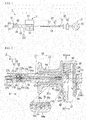
- the endoscope system 1 includes a suture-needle holder 2 of the present embodiment, and an endoscope 3.
- the endoscope 3 has an insertion part 11.
- a channel 12 through which the suture-needle holder 2 is instable is formed in the insertion part 11.
- the configuration of the endoscope 3 is not particularly limited.
- the endoscope 3 includes a flexible insertion part 11 to be inserted into the inside of a stomach from a mouth in the present embodiment.
- the term 'flexibility' means having bending rigidity (flexibility) to such a degree that the endoscope is deflected by operators, such as a surgeon.
- the suture-needle holder 2 is used by being combined with a suture needle D1 that is, for example, a curved needle.
- One end part of the suture thread D2 (refer to FIG. 8 ) is attached to the suture needle D1.
- the suture-needle holder 2 includes a sheath part 20 that is insertable into the inside of the body, a grasping part 30 that is provided at a distal end part of the sheath part 20, an operation wire 40 that is connected to the grasping part 30 and is movable relative to the sheath part 20 along a longitudinal axis C1 of the sheath part 20, and an operation part 50 that is connected to the to the sheath part 20.
- the grasping part 30 side with respect to the operation part 50 is referred to as a distal end side
- the operation part 50 side with respect to the grasping part 30 is referred to a proximal end side.
- the sheath part 20 has a flexible sheath 21, and a rotor 22 connected to a proximal end part of the sheath 21.
- a flange 21a is formed on an outer peripheral surface of the proximal end part of the sheath 21 over its entire circumference.
- a key protrusion 21b that protrudes from an outer peripheral surface of the flange 21a to a radial outer side of the sheath part 20 is formed in a portion of the sheath part 20 in a circumferential direction in an outer peripheral surface of the flange 21a.
- the sheath 21 is formed of a material having flexibility, such as a coiled sheath.
- the flange 21a and the key protrusion 21b are integrally formed of metal, such as stainless steel or titanium, and are fixed to the proximal end part of the sheath 21 by welding or the like.
- the internal diameter of at larger-diameter part 22b formed on the proximal end side of the rotor 22 is greater than the internal diameter of a smaller-diameter part 22a formed on the distal end side of the rotor 22 formed in a cylindrical shape.
- An engaging groove 22c is formed on an inner peripheral surface of the smaller-diameter part 22a over its entire circumference.
- a key groove 22d that extends from a bottom surface of the engaging groove 22c to the radial outer side is formed in a portion of the bottom surface of the engaging groove 22c in the circumferential direction.
- a proximal end part of the larger-diameter part 22b is formed in the shape of a rod such that a cutout (its reference sign is omitted) is formed by both radial sides sandwiching a support part 22e being cut out, and thereby the support part 22e extends toward the proximal end side.
- a proximal end part of the support part 22e is provided with a protruding part 22g that protrudes to a radial inner side.
- the protruding part 22g is formed, for example, in a columnar shape.
- An engaging part 22h is provided at the position of an inner peripheral surface of the proximal end part of the larger-diameter part 22b that faces the protruding part 22g.
- the engaging part 22h is formed, for example, in the shape of a rib that extends in the circumferential direction.
- the smaller-diameter part 22a, the larger-diameter part 22b, the support part 22e, the protruding part 22g, and the engaging part 22h are integrally formed of metal, such as stainless steel or titanium.
- the sheath 21 is inserted through the rotor 22, the flange 21a of the sheath 21 is engaged with the engaging groove 22c of the rotor 22, and the key protrusion 21b of the sheath 21 is engaged with the key groove 22d of the rotor 22.
- the engaging groove 22c, the flange 21a and the key groove 22d, and the key protrusion 21b are fixed with an adhesive, welding, or the like that is not illustrated.
- the sheath 21 and the rotor 22 are integrated with each other, moved in a direction aligned with the longitudinal axis C1 or rotated around the longitudinal axis C1.
- the operation wire 40 is inserted through the sheath 21 and the rotor 22.
- a coil spring (elastic member) 24 is disposed within the larger-diameter part 22b of the rotor 22.
- a distal end part of the coil spring 24 is connected to a stepped part (its reference sign is omitted) that is formed between the smaller-diameter part 22a and the larger-diameter part 22b of the rotor 22.
- the operation wire 40 is inserted into the coil spring 24.
- the grasping part 30 has a grasping member 31 and a grasping member 32.
- the grasping member 31 is fixed to the distal end part of the sheath 21 via a support member 33.
- the grasping member 32 is supported so as to be rotatable a pin 34 attached to the support member 33.
- a distal end part of the operation wire 40 is connected to a proximal end part of the grasping member 32 via a link member that is not illustrated.
- FIG. 1 illustrates an open state where the operation wire 40 is moved to the distal end side to the sheath 21 and distal end parts of the grasping member 31 and the grasping member 32 are spaced apart from each other and are open.
- a closed state where the grasping member 32 moves to a position Q1 and the distal end parts of the grasping member 31 and the grasping member 32 approach each other and are closed is brought about.
- the suture needle D1 can be grasped between the grasping member 31 and the grasping member 32.
- the operation wire 40 is connected to the grasping member 31 and the grasping member 32, and can be actuated by moving relative to the sheath 21 along the longitudinal axis of the sheath 21 such that the grasping member 31 and the grasping member 32 are open and closed therebetween.
- the operation wire 40 is formed of a single wire, a stranded wire, or the like.
- a tubular fixing member 41 illustrated in FIG. 2 is attached to a proximal end part of the operation wire 40 by brazing or the like.
- the operation part 50 is formed in a shaft shape extending along the longitudinal axis C1, and has an operation part body 51 that is connected to the rotor 22 of the sheath part 20, and a slider (traction member) 52 that is slidably provided along the longitudinal axis C1 with respect to the operation part body 51.
- the operation part 50 is a so-called slider-type handle.
- the operation part body 51 is grasped by a surgeon.
- a plurality of tooth parts 54 are formed along the longitudinal axis C1 in a side surface 51a parallel to the longitudinal axis C1 of the operation part body 51.
- an orthogonal surface 54a orthogonal to the longitudinal axis C1 and an inclined surface 54b spaced apart from the longitudinal axis C1 as it becomes closer to the proximal end side is formed in each tooth part 54.
- a finger hooking ring 55 is attached to a proximal end part of the operation part body 51 (refer to FIG. 1 ).
- the smaller-diameter part 56 having a smaller external diameter than the proximal end side is formed at a distal end part of the operation part body 51.
- the section of the smaller-diameter part 56 by a plane orthogonal the longitudinal axis C1 is formed in a cylindrical shape.
- a flange 56a is formed on an outer peripheral surface of a distal end part of the smaller-diameter part 56 over its entire circumference.
- the smaller-diameter part 56 of the operation part body 51 is inserted into the larger-diameter part 22b of the rotor 22.
- the flange 56a of the operation part body 51 and the engaging part 22h of the rotor 22 are engaged with each other, and the smaller-diameter part 56 of the operation part body 51 and rotor 22 slide on each other. Accordingly, the operation part body 51 of the operation part 50 can move in a direction aligned with the longitudinal axis C1 and around the longitudinal axis C1 with respect to the sheath part 20.
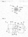
- a first groove part 56c and a second groove part 56d are formed in an outer peripheral surface 56b of the smaller-diameter part 56.
- the first groove part 56c has a distal end and a proximal end, and extends along the longitudinal axis C1 from the distal end to the proximal end.
- the second groove part 56d has one end connected to the proximal end of the first groove part 56c, and the other end at a position spaced apart from the one end in a spiral direction around the longitudinal axis C1, extends from one end to the other end, and is spirally formed.
- a third groove part 56e and a third fourth groove part 56f are formed in the outer peripheral surface 56b of the smaller-diameter part 56.
- the third groove part 56e has a distal end and a proximal end, the proximal end is connected to the other end of the second groove part, and extends along the longitudinal axis C1 from the proximal end to the distal end.
- the fourth groove part 56f extends around the longitudinal axis C1 so as to connect the distal end of the third groove part and the distal end of the first groove part to each other, and the fourth groove part 56f that is spirally formed is exemplified in the present embodiment.
- the groove parts 56c and 56e are linearly formed.
- the length of the first groove part 56c in the longitudinal axis C1 is equal to or smaller than the total length (the pitch of the tooth parts 54 x the number of the tooth parts 54) of the plurality of tooth parts 54 in the longitudinal axis C1.
- the second groove part 56d extends toward a first side (first direction) X1 around the longitudinal axis C1 as it becomes closer to the proximal end side.
- the fourth groove part 56f extends toward a second side (second direction) X2 around the longitudinal axis C1 as it becomes closer to the distal end side.
- a distal end of the fourth groove part 56f is connected to the distal end of the first groove part 56c.
- the groove parts 56d and 56f are formed in a spiral shape having the longitudinal axis C1 as a spiral axis.
- a lead angle ⁇ 4 of the fourth groove part 56f is smaller than a lead angle ⁇ 2 of the second groove part 56d.
- the width of the groove parts 56c, 56d, 56e, and 56f is slightly greater than the external diameter of the protruding part 22g of the rotor 22.
- the protruding part 22g of the rotor 22 are engaged with the groove parts 56c, 56d, 56e, and 56f, and are movable (slidable) along the groove parts 56c, 56d, 56e, and 56f.
- the protruding part 22g moves from the distal end side to the proximal end side within the first groove part 56c by pulling the operation wire 40 with respect to the sheath 21 (operation part body), the grasping members 31 and 32 become from the open state into the closed state, and grasp the suture needle D1.
- the operation wire 40 in the first state is further pulled, and thereby the protruding part 22g moves from one end toward the other end within the second groove part 56d, and the rotor 22, the sheath 21, and the grasping part 30 are integrated with each other together with the protruding part 22g, and rotates around the longitudinal axis C1 along the second groove part 56d. That is, in a state the suture needle D1 is grasped by the grasping members 31 and 32, the grasping part 30 is turned around the longitudinal axis C1 with respect to the operation part body 51 together with the sheath 21, and the suture needle D1 is punctured into tissue.
- the protruding part 22g moves from one end toward the other end within the fourth groove part 56f, and the rotor 22, the sheath 21, and the grasping part 30 are integrated with each other together with the protruding part 22g, and rotates around the longitudinal axis C1 along the fourth groove part 56f. That is, in a state where the grasping members 31 and 32 are spaced apart from each other and are open, the grasping part 30 rotates in a direction opposite to the direction of the rotation in the second state together with the sheath 21.
- a proximal end part of the coil spring 24 is connected to a distal end surface of the smaller-diameter part 56 of the operation part body 51.
- a slit 51b is formed on the longitudinal axis C1 of the operation part body 51.
- the operation wire 40 is inserted through the slit 51b.
- a recess 52a is formed on the longitudinal axis C1 in the slider 52.
- the fixing member 41 is disposed within the recess 52a, and the slider 52 is fixed to the proximal end part of the operation wire 40 by the fixing member 41 being engaged with the recess 52a.
- a slit 52f that extends along the longitudinal axis C1 illustrated in FIG. 5 is formed in the slider 52.
- the slider 52 can slide along the longitudinal axis C1 with respect to the operation part body 51 by the operation part body 51 being inserted through the slit 52f.
- a recess 52b that extends in a direction intersecting the longitudinal axis C1 from an outer surface of the slider 52 is formed on the proximal end side of the slider 52.
- a finger-hooking recess 52c is formed in an outer surface of the slider 52 around the longitudinal axis C1.
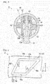
- a button 57 is inserted through an opening 52d that communicates with the outside in the recess 52b.
- a coupling plate 58 is provided opposite to the opening 52d across the longitudinal axis C1 within the recess 52b of the slider 52.
- the coupling plate 58 is connected to the button 57.
- a tooth part 59 is formed on the surface of the coupling plate 58 on the side of the longitudinal axis C1.
- an orthogonal surface 59a orthogonal to the longitudinal axis C1 and an inclined surface 59b spaced apart from the longitudinal axis C1 as it becomes closer to the proximal end side are formed in the tooth part 59.
- a coil spring 60 is disposed between a bottom surface of the recess 52b of the slider 52, and the coupling plate 58.
- the coil spring 60 biases the coupling plate 58 to the longitudinal axis C1 side.
- a ratchet mechanism 61 is constituted by the plurality of tooth parts 54, the button 57, the coupling plate 58, the tooth part 59, and the coil spring 60.
- the tooth part 59 of the coupling plate 58 comes into contact with the orthogonal surfaces 54a of the plurality of tooth parts 54 of the operation part body 51, the tooth part 59 is inhibited from moving to the distal end side with respect to the tooth parts 54.
- the slider 52 is inhibited from moving to the distal end side with respect to the operation part body 51 by the coupling plate 58 in which the tooth part 59 is formed being locked to an inner peripheral surface of the recess 52b.
- the inclined surface 59b of the tooth part 59 slides on the inclined surfaces 54b of the plurality of tooth parts 54, so that the slider 52 can be moved to the proximal end side with respect to the operation part body 51 even if the tooth part 59 of the coupling plate 58 comes into contact with the tooth parts 54 of the operation part body 51.
- the button 57 is moved and pushed in up to a position Q2 to the longitudinal axis C1 side while elastically deforming the coil spring 60.
- movement of the tooth parts 54 up to a position Q3 prevents the tooth part 59 of the coupling plate 58 from coming into contact with the tooth parts 54 of the operation part body 51.
- the slider 52 can be moved to both the distal end side and the proximal end side with respect to the operation part body 51.
- a tooth part 54A located closest to the proximal end side among the plurality of tooth parts 54 and the tooth part 59 are engaged with each other. That is, when the protruding part 22g is disposed within the first groove part 56c, the tooth parts 54 and the tooth part 59 are engaged with each other, but when the protruding part 22g is disposed within the second groove part 56d, the tooth parts 54 and the tooth part 59 are not engaged with each other.
- the slider 52 is inhibited from moving to the distal end side with respect to the operation part body 51, and is allowed to move to the proximal end side.
- the slider 52 is also allowed to move to any of the distal end side and the proximal end side with respect to the operation part body 51.
- the operation wire 40 moves to the proximal end side with respect to the operation part body 51, and the sheath 21, and the grasping members 31 and 32 is brought into the closed state.
- the operation wire 40 moves to the distal end side with respect to the operation part body 51 and the sheath 21 and the grasping members 31 and 32 is brought into the open state.
- the protruding part 22g is disposed within a proximal end part of the third groove part 56e outside a patient's body, and the grasping members 31 and 32 are brought into the closed state.
- the insertion part 11 of the endoscope 3 is inserted from a natural opening, such as a patient's mouth, and the insertion part 11 is held in a state where a distal end surface thereof is made to face the tissue that is a treatment target part.
- the sheath part 20 of the suture-needle holder 2 is inserted from the proximal end part of the channel 12 of the endoscope 3, and the grasping part 30 is made to protrude from a distal end part of the channel 12.
- the grasping members 31 and 32 are brought into the open state, and are turned to the second side (second direction) X2 around the longitudinal axis C1.
- the suture needle D1 conveyed inside the stomach by conveying means that is not illustrated is disposed between the grasping member 31 and the grasping member 32.
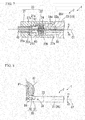
- the slider 52 is pulled back from a state where the protruding part 22g is disposed at the distal end part of the first groove part 56c. Accordingly, as illustrated in FIGS. 7 and 8 , the protruding part 22g moves to the proximal end side inside the first groove part 56c, the operation wire 40 moves to the proximal end side with respect to the sheath part 20, and the grasping members 31 and 32 are brought into the closed state and grasp the suture needle D1.
- the coil spring 24 is compressed in the direction aligned with the longitudinal axis C1 more than a state where the coil spring has a natural length. Since the plurality of tooth parts 54 and the tooth part 59 of the ratchet mechanism 61 are engaged with each other, the slider 52 can be pulled back, but the pulled-back slider 52 cannot be pushed in at a time.
- the surgeon pushes in the suture-needle holder 2 or adjusts the orientation in which a bending part (not illustrated) of the insertion part 11 of the endoscope 3 bends, thereby adjusting a positional relationship between tissue P1 and the suture needle D1.
- the protruding part 22g moves to the proximal end side inside the second groove part 56d, and the grasping members 31 and 32 and the sheath part 20 turn to the first side (first direction) X1 around the longitudinal axis C1 with respect to the operation part body 51.
- the coil spring 24 is further compressed in the direction aligned with the longitudinal axis C1, and the tissue P1 is punctured with a distal end part of the suture needle D1.
- the proximal end side of the coil spring 24 is twisted to the first side (first direction) X1 around the longitudinal axis C1.
- the protruding part 22g is disposed at a proximal end part of the second groove part 56d.
- the suture needle D1 can be extracted from the tissue P1 by pushing in the slider 52 to turn the grasping part 30 to the second side (second direction) X2 around the longitudinal axis C1. In this case, the protruding part 22g cannot be moved up to the inside of the first groove part 56c by the ratchet mechanism 61.
- a place where the tissue P1 is punctured with the suture needle D1 is adjusted, and the slider 52 is pulled back, and the tissue P1 is punctured with the suture needle D1.
- the protruding part 22g is moved to the distal end side inside the third groove part 56e with the elastic force of the coil spring 24, and the grasping members 31 and 32 are brought into the open state and releases the suture needle D1. Since the lead angle ⁇ 4 of the fourth groove part 56f is smaller than the lead angle ⁇ 2 of the second groove part 56d, the positions of the grasping members 31 and 32 when releasing the suture needle D1 become closer to the distal end side.
- the protruding part 22g is moved to the distal end side inside the fourth groove part 56f by the elastic force of the coil spring 24.
- the grasping members 31 and 32 and the sheath part 20 turn to the second side (second direction) X2 around the longitudinal axis C1 with respect to the operation part body 51. That is, the orientations of the grasping members 31 and 32 around the longitudinal axis C1 return to the orientations when the grasping members 31 and 32 grasp the suture needle D1.
- the slider 52 is pulled back if necessary, and as illustrated in FIG. 13 , the grasping members 31 and 32 are brought into the closed state, and the distal end part of the suture needle D1 is regrasped, that is, reheld.
- the grasping member 31 and 32 and the like turn to the first side (first direction) X1 around the longitudinal axis C1, the suture needle D1 passes through the tissue P1, and suture thread D2 passes through the tissue P1.
- the operation in which the grasping members 31 and 32 are brought into the closed state and grasp the suture needle D1 and an operation in which the sheath part 20 is turned to the first side (first direction) X1 around the longitudinal axis C1 and the tissue P1 is punctured with the suture needle D1 are continuously performed. Consequently, simply by pulling back the slider 52, the rotation operation of the sheath part 20 can also be performed and the operability of the slider 52 and the sheath part 20 can be improved.
- the groove parts 56e and 56f are formed in the outer peripheral surface 56b of the operation part body 51. If the slider 52 is pushed in, an operation in which the suture needle D1 is released, and an operation in which the sheath part 20 is turned to the second side (second direction) X2 around the longitudinal axis C1 are continuously performed. Consequently, simply by pushing in the slider 52, the rotation operation of the sheath part 20 can also be performed and the operability of the slider 52 and the sheath part 20 can be further improved.
- the suture-needle holder 2 includes the coil spring 24, so that the slider 52 can be moved to the distal end side by the elastic force of the coil spring 24 even if the slider 52 is not pushed in after the slider 52 is pulled back.
- the suture-needle holder 2 including the ratchet mechanism 61, so that the suture needle D1 once grasped by the grasping members 31 and 32 can be prevented from being released, and the puncturing position of the tissue P1 by the suture needle D1 can be easily adjusted.
- the protruding part 22g moves from the first groove part 56c to the second groove part 56d. Consequently, by the locking between the plurality of tooth parts 54 and the tooth part 59, the open/closed state of the grasping members 31 and 32 can be detected and the opening/closing operation of the grasping members 31 and 32 can be easily performed.
- the configuration of the suture-needle holder 2 of the present embodiment can be variously deformed as described below.
- a recessed part 65b may be formed at an end part on the first groove part 56c side in a side surface 65a on the distal end side of the second groove part 56d.
- the recessed part 65b is recessed toward the distal end side so as to house at least a portion of the protruding part 22g.
- the protruding part 22g If the protruding part 22g is housed within the recessed part 65b, the protruding part 22g does not easily comes out of the recessed part 65b even if the elastic force is exerted on the protruding part 22g like the arrow B1. Consequently, the protruding part 22g can be more reliably prevented from returning to the inside of the first groove part 56c from the inside of the second groove part 56d.
- a projecting part 65e may be formed in a side surface 65d of the second groove part 56d on the proximal end side, in addition to the respective components of the suture-needle holder 2A of the above modification example.
- the projecting part 65e is formed in the portion of the side surface 65d facing the recessed part 65b so as to protrude toward the distal end side.
- a meandering part 65f in which the second groove part 56d meanders is formed by the projecting part 65e and the recessed part 65b.
- the width of the meandering part 65f is set such that the protruding part 22g passes therethrough.
- the protruding part 22g that has entered the recessed part 65b once does not easily come out of the recessed part 65b by forming the projecting part 65e and the recessed part 65b in the second groove part 56d.
- a recessed part 66b is formed at an end part on the second groove part 56d in a side surface 66a on the first side (first direction) X1 around the longitudinal axis C1 of the first groove part 56c, and a projecting part 66d may be formed on a side surface 66c on the second side (second direction) X2 around the longitudinal axis C1 of the first groove part 56c.
- a meandering part 66e in which the first groove part 56c meanders is formed by the recessed part 66b and the projecting part 66d.
- an elastic force to move the protruding part 22g to the second side (second direction) X2 around the longitudinal axis C1 is exerted by the coil spring 24 by the proximal end side of the coil spring 24 being twisted to the first side (first direction) X1 around the longitudinal axis C1.
- the protruding part 22g is housed within a depression 66f formed adjacent to the proximal end side of the projecting part 66d in the side surface 66c of the first groove part 56c. It is preferable that a length by which the projecting part 66d protrudes from the side surface 66c of the first groove part 56c is equal to or greater than a certain value.
- the protruding part 22g is housed within the depression 66f, so that the protruding part 22g can be more reliably prevented from returning to the inside of the first groove part 56c from the inside of the second groove part 56d.
- the protruding part 22g easily passes through the first groove part 56c to the proximal end side by not only the projecting part 66d but also the recessed part 66b being formed.
- a second projecting part 66g may be formed at an end part on the second groove part 56d side in the side surface 66c of the first groove part 56c.
- the second projecting part 66g protrudes in a semicircular shape from the side surface 66c.
- a distance L between the side surface 66a and the second projecting part 66g is slightly smaller than the external diameter of the protruding part 22g.
- the groove parts 56e and 56f may not be formed in the outer peripheral surface 56b of the operation part body 51. This is because the operation of grasping the suture needle D1 to puncture of the tissue P1 with the suture needle D1 can be performed at a time if the groove parts 56c and 56d are formed in the outer peripheral surface 56b of the operation part body 51.
- wall parts of regions R1 and R2 between the engaging groove 22c and the key groove 22d in FIG. 7 , and the larger-diameter part 22b may not be formed in the rotor 22. That is, with respect to the rotor 22, the sheath 21 just has to be locked to the first side (first direction) X1 and the second side (second direction) X2 around the longitudinal axis C1, and the distal end side, and may not be locked to the proximal end side.
- the elastic member is the coil spring 24
- the elastic member may be rubber or the like.
- the suture-needle holder 2 may not include the coil spring 24. This is because a surgeon just has to push in and operate the slider 52.
- the rotor may be configured so as to be fixed to the sheath in a state where the rotor is inserted through the sheath.
- the endoscope 3 includes the flexible insertion part 11. However, though the endoscope may include a rigid insertion part with greater bending rigidity than the flexible insertion part 11.
- the operation part 50 is a slider-type handle.
- the operation part may be a so-called in-line type handle in which one end of the traction member is turnably attached to the operation part body and the proximal end part of the operation wire 40 is connected to the other end of this traction member. This is because the operation wire 40 can be moved in the direction aligned with the longitudinal axis C1 with respect to the sheath part 20 also by operating the traction member of the operation part.
- the suture-needle holder and the endoscope system of the above one embodiment can improve the operability of the traction member and the sheath part.
Landscapes
- Health & Medical Sciences (AREA)
- Life Sciences & Earth Sciences (AREA)
- Surgery (AREA)
- Heart & Thoracic Surgery (AREA)
- Engineering & Computer Science (AREA)
- Biomedical Technology (AREA)
- Nuclear Medicine, Radiotherapy & Molecular Imaging (AREA)
- Medical Informatics (AREA)
- Molecular Biology (AREA)
- Animal Behavior & Ethology (AREA)
- General Health & Medical Sciences (AREA)
- Public Health (AREA)
- Veterinary Medicine (AREA)
- Surgical Instruments (AREA)
Claims (12)
- Porte-aiguille de suture (2, 2A, 2B, 2C, 2D) comprenant :une partie gaine (20) capable d'être introduite dans l'intérieur d'un corps ;une paire d'éléments de saisie (31, 32) fixés à une partie d'extrémité distale de la partie gaine (20) et capables de saisir une aiguille de suture (D1) en se rapprochant l'un de l'autre et en étant fermés ;un fil d'actionnement (40) relié à la paire d'éléments de saisie (31, 32) et actionné pour ouvrir et fermer la paire d'éléments de saisie (31, 32) en se déplaçant par rapport à la partie gaine (20) le long d'un axe longitudinal (C1) de la partie gaine (20) ; etun corps de partie d'actionnement (51) ayant une forme d'arbre pour s'étendre le long de l'axe longitudinal (C1) et attaché au fil d'actionnement (40), et relié à la partie gaine (20) de telle sorte que la partie gaine (20) est mobile dans une direction alignée avec l'axe longitudinal (C1) et apte à tourner autour de l'axe longitudinal (C1) par rapport au corps de partie d'actionnement (51),une première partie rainure (56c) ayant une extrémité distale et une extrémité proximale et s'étendant le long de l'axe longitudinal (C1), et une deuxième partie rainure (56d) qui est formée en spirale et a une première extrémité reliée à l'extrémité proximale de la première partie rainure (56c) et l'autre extrémité dans une position séparée de la première extrémité dans une direction de spirale alignée avec l'axe longitudinal (C1), et s'étendant de manière proximale de la première extrémité à l'autre extrémité, étant formées dans une surface périphérique externe (56b) du corps de partie d'actionnement (51),
une partie d'extrémité proximale de la partie gaine (20) comportant une partie en saillie (22g) qui fait saillie vers un côté interne radial de la partie gaine (20),
la partie en saillie (22g) ayant un premier état dans lequel la partie en saillie (22g) se déplace dans un état dans lequel la partie en saillie (22g) est engagée à l'intérieur de la première partie rainure (56c), et un deuxième état dans lequel la partie en saillie (22g) se déplace dans un état dans lequel la partie en saillie (22g) est engagée à l'intérieur de la deuxième partie rainure (56d),
dans le premier état, le fil d'actionnement (40) étant apte à être tiré par rapport à la partie gaine (20) et, de ce fait, la partie en saillie (22g) étant déplacée d'un côté extrémité distale de la première partie rainure (56c) à un côté extrémité proximale à l'intérieur de la première partie rainure (56c) et la paire d'éléments de saisie (31, 32) étant fermée pour saisir l'aiguille de suture (D1), et
dans le deuxième état, le fil d'actionnement (40) dans le premier état étant davantage tiré par rapport à la partie gaine (20) et, de ce fait, la partie en saillie (22g) étant déplacée de la première extrémité de la deuxième partie rainure (56d) vers l'autre extrémité à l'intérieur de la deuxième partie rainure (56d), et la paire d'éléments de saisie (31, 32) et la partie de gaine (20) étant tournées autour de l'axe longitudinal (C1) par rapport au corps de partie d'actionnement (51) dans un état dans lequel la paire d'éléments de saisie (31, 32) a saisi l'aiguille de suture (D1). - Porte-aiguille de suture (2, 2A, 2B, 2C, 2D) selon la revendication 1, dans lequel
la première partie rainure (56c) et la deuxième partie rainure (56d) sont formées dans la surface périphérique externe (56b) du corps de partie d'actionnement (51), et
la partie en saillie (22g) est prévue à une partie d'extrémité proximale de la partie gaine (20). - Porte-aiguille de suture (2, 2A, 2B, 2C, 2D) selon la revendication 2, dans lequel
une troisième partie rainure (56e) ayant une extrémité distale et une extrémité proximale et s'étendant le long de l'axe longitudinal (C1) de l'extrémité proximale à l'extrémité distale, l'extrémité proximale étant reliée à l'autre extrémité de la deuxième partie rainure (56d), et une quatrième partie rainure (56f) s'étendant autour de l'axe longitudinal (C1) de façon à relier l'extrémité distale de la troisième partie rainure (56e) et l'extrémité distale de la première partie rainure (56c) l'une à l'autre, sont formées dans la surface périphérique externe (56b) du corps de partie d'actionnement (51),
la partie en saillie (22g) a un troisième état dans lequel la partie en saillie (22g) se déplace dans un état dans lequel la partie en saillie (22g) est engagée avec l'intérieur de la troisième partie rainure (56e), et un quatrième état dans lequel la partie en saillie (22g) se déplace dans un état dans lequel la partie en saillie (22g) est engagée avec l'intérieur de la quatrième partie rainure (56f),
dans le troisième état, la partie en saillie (22g) est déplacée du côté extrémité proximale vers le côté extrémité distale à l'intérieur de la troisième partie rainure (56e), et la paire d'éléments de saisie (31, 32) sont espacés l'un de l'autre et sont ouverts pour libérer l'aiguille de suture (D1), et
dans le quatrième état, si la partie en saillie (22g) est déplacée de la première extrémité vers l'autre extrémité à l'intérieur de la quatrième partie rainure (56f), la paire d'éléments de saisie (31, 32) et la partie gaine (20) sont tournées dans une direction opposée à une direction de rotation de la paire d'éléments de saisie (31, 32) et de la partie gaine (20) dans le deuxième état dans un état dans lequel la paire d'éléments de saisie (31, 32) sont ouverts. - Porte-aiguille de suture (2, 2A, 2B, 2C, 2D) selon la revendication 2, comprenant en outre un élément élastique (24) relié à la partie gaine (20) et au corps de partie d'actionnement (51), respectivement.
- Porte-aiguille de suture (2, 2A, 2B, 2C, 2D) selon la revendication 2,
dans lequel une partie d'extrémité proximale du fil d'actionnement (40) comporte un élément de traction (52) fixé de manière mobile au corps de partie d'actionnement (51) pour déplacer le fil d'actionnement (40) dans une direction alignée avec l'axe longitudinal (C1) par rapport au corps de partie d'actionnement (51). - Porte-aiguille de suture (2, 2A, 2B, 2C, 2D) selon la revendication 5, comprenant en outre :un mécanisme à cliquet (61) qui permet un mouvement de l'élément de traction (52) vers le côté extrémité proximale par rapport au corps de partie d'actionnement (51) et limite un mouvement de l'élément de traction (52) vers le côté extrémité distale lorsque la partie en saillie (22g) est disposée à l'intérieur de la première partie rainure (56c), et permet les mouvements de l'élément de traction (52) vers le côté extrémité proximale et le côté extrémité distale par rapport au corps de partie d'actionnement (51) lorsque la partie en saillie (22g) est disposée à l'intérieur de la deuxième partie rainure (56d).
- Porte-aiguille de suture (2A) selon la revendication 2,
dans lequel une partie renfoncée (65b), qui est renfoncée vers le côté extrémité distale, est capable de recevoir au moins une portion de la partie en saillie (22g) et est formée à une partie d'extrémité sur le côté première partie rainure (56c) dans une surface latérale de la deuxième partie rainure (56d) sur le côté extrémité distale. - Porte-aiguille de suture (2B) selon la revendication 7,
dans lequel une partie en projection (65e) qui fait saillie vers le côté extrémité distale est formée dans une partie qui fait face à la partie renfoncée (65b), dans une surface latérale de la deuxième partie rainure (56d) sur le côté extrémité proximale. - Porte-aiguille de suture (2D) selon la revendication 2,
dans lequel une seconde partie en projection (66g) est formée à une première partie d'extrémité d'une surface latérale de la première partie rainure (56c), la première partie d'extrémité étant proche de la deuxième partie rainure (56d). - Porte-aiguille de suture (2, 2A, 2B, 2C, 2D) selon la revendication 3,
dans lequel la quatrième partie rainure (56f) s'étend autour de l'axe longitudinal (C1) dans une direction (X2) différente d'une direction (X1) de la deuxième partie rainure (56d), et est en forme de spirale. - Porte-aiguille de suture (2, 2A, 2B, 2C, 2D) selon la revendication 3,
dans lequel une inclinaison (α4) de la quatrième partie rainure (56f) est plus petite qu'une inclinaison (α2) de la deuxième partie rainure (56d). - Système d'endoscope (1) comprenant :le porte-aiguille de suture (2, 2A, 2B, 2C, 2D) selon la revendication 2 ; etun endoscope (3) qui a une partie d'introduction souple (11), et un canal (12), à travers lequel le porte-aiguille de suture (2, 2A, 2B, 2C, 2D) est apte à être introduite, prévu dans la partie d'insertion (11).
Applications Claiming Priority (2)
| Application Number | Priority Date | Filing Date | Title |
|---|---|---|---|
| JP2014137886 | 2014-07-03 | ||
| PCT/JP2015/069276 WO2016002932A1 (fr) | 2014-07-03 | 2015-07-03 | Porte-aiguille de suture et système d'endoscope |
Publications (3)
| Publication Number | Publication Date |
|---|---|
| EP3165175A1 EP3165175A1 (fr) | 2017-05-10 |
| EP3165175A4 EP3165175A4 (fr) | 2018-01-03 |
| EP3165175B1 true EP3165175B1 (fr) | 2019-03-06 |
Family
ID=55019458
Family Applications (1)
| Application Number | Title | Priority Date | Filing Date |
|---|---|---|---|
| EP15816008.5A Active EP3165175B1 (fr) | 2014-07-03 | 2015-07-03 | Porte-aiguille de suture |
Country Status (5)
| Country | Link |
|---|---|
| US (1) | US9737295B2 (fr) |
| EP (1) | EP3165175B1 (fr) |
| JP (1) | JP6045755B2 (fr) |
| CN (1) | CN106659497B (fr) |
| WO (1) | WO2016002932A1 (fr) |
Families Citing this family (9)
| Publication number | Priority date | Publication date | Assignee | Title |
|---|---|---|---|---|
| WO2019180867A1 (fr) * | 2018-03-22 | 2019-09-26 | オリンパス株式会社 | Porte-aiguille et son procédé d'utilisation |
| JP7583388B2 (ja) * | 2018-08-24 | 2024-11-14 | 株式会社産業情報総合研究所 | 把持器、持針器、挟持アタッチメント |
| JP7142724B2 (ja) * | 2019-01-23 | 2022-09-27 | オリンパス株式会社 | エネルギ処置具 |
| WO2021079461A1 (fr) * | 2019-10-24 | 2021-04-29 | オリンパス株式会社 | Porte-aiguille pour endoscope et procédé de manipulation d'aiguille de suture |
| JP7349553B2 (ja) * | 2020-03-05 | 2023-09-22 | オリンパス株式会社 | 内視鏡用持針器 |
| WO2022079788A1 (fr) * | 2020-10-13 | 2022-04-21 | オリンパス株式会社 | Instrument de traction, système de traction, procédé de traction de fil de suture, et procédé de suture |
| CN115996681B (zh) * | 2020-10-13 | 2025-11-28 | 奥林巴斯株式会社 | 牵引器具、缝合线的牵引方法及缝合方法 |
| JP7697218B2 (ja) * | 2021-02-03 | 2025-06-24 | ブラザー工業株式会社 | 縫合装置 |
| WO2022187475A1 (fr) | 2021-03-03 | 2022-09-09 | Acustitch, Llc | Système et procédé de reconstruction et de réparation osseuses et dispositif d'implant |
Family Cites Families (14)
| Publication number | Priority date | Publication date | Assignee | Title |
|---|---|---|---|---|
| JP2545558Y2 (ja) * | 1990-10-23 | 1997-08-25 | ジョンソン・エンド・ジョンソンメディカル株式会社 | 深部縫合器 |
| US5458608A (en) * | 1993-06-03 | 1995-10-17 | Surgin Surgical Instrumentation Inc. | Laparoscopic instruments and methods |
| US5443479A (en) * | 1994-02-07 | 1995-08-22 | Bressi, Jr.; Thomas E. | Surgical forceps |
| US5938668A (en) * | 1994-10-07 | 1999-08-17 | United States Surgical | Surgical suturing apparatus |
| AU9014198A (en) * | 1997-08-01 | 1999-02-22 | Inbae Yoon | Surgical instrument with multiple spreadable end effectors mounted for arcuate movement |
| US9314235B2 (en) * | 2003-02-05 | 2016-04-19 | Smith & Nephew, Inc. | Tissue anchor and insertion tool |
| CN2675055Y (zh) * | 2003-09-03 | 2005-02-02 | 王光明 | 防滑持针器 |
| JP4624085B2 (ja) * | 2003-12-01 | 2011-02-02 | 尚志 鍾 | 内視鏡用処置具 |
| JP4681961B2 (ja) * | 2005-01-14 | 2011-05-11 | オリンパスメディカルシステムズ株式会社 | 外科用処置具 |
| US20080243180A1 (en) * | 2005-01-26 | 2008-10-02 | Yen-Yue Lin | Surgery fixation forceps |
| US20090198098A1 (en) | 2008-02-01 | 2009-08-06 | Olympus Medical Systems Corp. | Endoscope treatment instrument |
| US8231640B2 (en) * | 2008-07-31 | 2012-07-31 | Olympus Medical Systems Corp. | Suture instrument |
| JP2011098160A (ja) * | 2009-11-09 | 2011-05-19 | Teikyo Univ | 手術用持針器 |
| CN202568376U (zh) * | 2012-04-05 | 2012-12-05 | 王春恒 | 一种带有照明装置的阑尾荷包缝合钳 |
-
2015
- 2015-07-03 EP EP15816008.5A patent/EP3165175B1/fr active Active
- 2015-07-03 WO PCT/JP2015/069276 patent/WO2016002932A1/fr not_active Ceased
- 2015-07-03 JP JP2016524609A patent/JP6045755B2/ja active Active
- 2015-07-03 CN CN201580035019.2A patent/CN106659497B/zh active Active
-
2016
- 2016-12-16 US US15/382,470 patent/US9737295B2/en active Active
Non-Patent Citations (1)
| Title |
|---|
| None * |
Also Published As
| Publication number | Publication date |
|---|---|
| US9737295B2 (en) | 2017-08-22 |
| EP3165175A1 (fr) | 2017-05-10 |
| WO2016002932A1 (fr) | 2016-01-07 |
| US20170095249A1 (en) | 2017-04-06 |
| JPWO2016002932A1 (ja) | 2017-04-27 |
| CN106659497A (zh) | 2017-05-10 |
| EP3165175A4 (fr) | 2018-01-03 |
| JP6045755B2 (ja) | 2016-12-14 |
| CN106659497B (zh) | 2019-06-18 |
Similar Documents
| Publication | Publication Date | Title |
|---|---|---|
| EP3165175B1 (fr) | Porte-aiguille de suture | |
| US9913641B2 (en) | Surgical instrument and tissue dissecting unit | |
| EP2997912B1 (fr) | Outil de traitement endoscopique | |
| US10835220B2 (en) | Self-articulating joint for a minimally invasive surgical apparatus | |
| EP2097019B1 (fr) | Dispositifs manuellement articulés | |
| JP4855765B2 (ja) | 内視鏡用治療装置 | |
| EP2730233B1 (fr) | Anse de suture à manchon rétractable | |
| US9277932B2 (en) | Endoscopic scissors instrument with friction enhancing tissue stops | |
| EP3351189B1 (fr) | Instrument de traitement endoscopique | |
| US8690909B2 (en) | Endoscopic instrument with bi-laterally widened cam-slot at end effector | |
| US9782190B2 (en) | Surgical instrument | |
| WO2016147464A1 (fr) | Dispositif de suture | |
| WO2020105253A1 (fr) | Outil de traitement d'endoscope | |
| US10492811B2 (en) | Rotatable endoscopic instrument | |
| US20210068812A1 (en) | Suturing closure scope with alternative needle orientation | |
| EP3643251B1 (fr) | Dispositif de suture | |
| JP2021137241A (ja) | 内視鏡用縫合器及び内視鏡 | |
| US20200163662A1 (en) | Retractor |
Legal Events
| Date | Code | Title | Description |
|---|---|---|---|
| STAA | Information on the status of an ep patent application or granted ep patent |
Free format text: STATUS: THE INTERNATIONAL PUBLICATION HAS BEEN MADE |
|
| PUAI | Public reference made under article 153(3) epc to a published international application that has entered the european phase |
Free format text: ORIGINAL CODE: 0009012 |
|
| STAA | Information on the status of an ep patent application or granted ep patent |
Free format text: STATUS: REQUEST FOR EXAMINATION WAS MADE |
|
| 17P | Request for examination filed |
Effective date: 20170117 |
|
| AK | Designated contracting states |
Kind code of ref document: A1 Designated state(s): AL AT BE BG CH CY CZ DE DK EE ES FI FR GB GR HR HU IE IS IT LI LT LU LV MC MK MT NL NO PL PT RO RS SE SI SK SM TR |
|
| AX | Request for extension of the european patent |
Extension state: BA ME |
|
| DAV | Request for validation of the european patent (deleted) | ||
| DAX | Request for extension of the european patent (deleted) | ||
| A4 | Supplementary search report drawn up and despatched |
Effective date: 20171130 |
|
| RIC1 | Information provided on ipc code assigned before grant |
Ipc: A61B 17/28 20060101ALI20171124BHEP Ipc: A61B 17/06 20060101AFI20171124BHEP |
|
| GRAP | Despatch of communication of intention to grant a patent |
Free format text: ORIGINAL CODE: EPIDOSNIGR1 |
|
| STAA | Information on the status of an ep patent application or granted ep patent |
Free format text: STATUS: GRANT OF PATENT IS INTENDED |
|
| INTG | Intention to grant announced |
Effective date: 20181008 |
|
| GRAS | Grant fee paid |
Free format text: ORIGINAL CODE: EPIDOSNIGR3 |
|
| GRAA | (expected) grant |
Free format text: ORIGINAL CODE: 0009210 |
|
| STAA | Information on the status of an ep patent application or granted ep patent |
Free format text: STATUS: THE PATENT HAS BEEN GRANTED |
|
| AK | Designated contracting states |
Kind code of ref document: B1 Designated state(s): AL AT BE BG CH CY CZ DE DK EE ES FI FR GB GR HR HU IE IS IT LI LT LU LV MC MK MT NL NO PL PT RO RS SE SI SK SM TR |
|
| REG | Reference to a national code |
Ref country code: GB Ref legal event code: FG4D |
|
| REG | Reference to a national code |
Ref country code: CH Ref legal event code: EP Ref country code: AT Ref legal event code: REF Ref document number: 1103498 Country of ref document: AT Kind code of ref document: T Effective date: 20190315 |
|
| REG | Reference to a national code |
Ref country code: DE Ref legal event code: R096 Ref document number: 602015026034 Country of ref document: DE |
|
| REG | Reference to a national code |
Ref country code: IE Ref legal event code: FG4D |
|
| REG | Reference to a national code |
Ref country code: NL Ref legal event code: MP Effective date: 20190306 |
|
| REG | Reference to a national code |
Ref country code: LT Ref legal event code: MG4D |
|
| PG25 | Lapsed in a contracting state [announced via postgrant information from national office to epo] |
Ref country code: LT Free format text: LAPSE BECAUSE OF FAILURE TO SUBMIT A TRANSLATION OF THE DESCRIPTION OR TO PAY THE FEE WITHIN THE PRESCRIBED TIME-LIMIT Effective date: 20190306 Ref country code: NO Free format text: LAPSE BECAUSE OF FAILURE TO SUBMIT A TRANSLATION OF THE DESCRIPTION OR TO PAY THE FEE WITHIN THE PRESCRIBED TIME-LIMIT Effective date: 20190606 Ref country code: SE Free format text: LAPSE BECAUSE OF FAILURE TO SUBMIT A TRANSLATION OF THE DESCRIPTION OR TO PAY THE FEE WITHIN THE PRESCRIBED TIME-LIMIT Effective date: 20190306 Ref country code: FI Free format text: LAPSE BECAUSE OF FAILURE TO SUBMIT A TRANSLATION OF THE DESCRIPTION OR TO PAY THE FEE WITHIN THE PRESCRIBED TIME-LIMIT Effective date: 20190306 |
|
| PG25 | Lapsed in a contracting state [announced via postgrant information from national office to epo] |
Ref country code: GR Free format text: LAPSE BECAUSE OF FAILURE TO SUBMIT A TRANSLATION OF THE DESCRIPTION OR TO PAY THE FEE WITHIN THE PRESCRIBED TIME-LIMIT Effective date: 20190607 Ref country code: RS Free format text: LAPSE BECAUSE OF FAILURE TO SUBMIT A TRANSLATION OF THE DESCRIPTION OR TO PAY THE FEE WITHIN THE PRESCRIBED TIME-LIMIT Effective date: 20190306 Ref country code: BG Free format text: LAPSE BECAUSE OF FAILURE TO SUBMIT A TRANSLATION OF THE DESCRIPTION OR TO PAY THE FEE WITHIN THE PRESCRIBED TIME-LIMIT Effective date: 20190606 Ref country code: LV Free format text: LAPSE BECAUSE OF FAILURE TO SUBMIT A TRANSLATION OF THE DESCRIPTION OR TO PAY THE FEE WITHIN THE PRESCRIBED TIME-LIMIT Effective date: 20190306 Ref country code: NL Free format text: LAPSE BECAUSE OF FAILURE TO SUBMIT A TRANSLATION OF THE DESCRIPTION OR TO PAY THE FEE WITHIN THE PRESCRIBED TIME-LIMIT Effective date: 20190306 Ref country code: HR Free format text: LAPSE BECAUSE OF FAILURE TO SUBMIT A TRANSLATION OF THE DESCRIPTION OR TO PAY THE FEE WITHIN THE PRESCRIBED TIME-LIMIT Effective date: 20190306 |
|
| REG | Reference to a national code |
Ref country code: AT Ref legal event code: MK05 Ref document number: 1103498 Country of ref document: AT Kind code of ref document: T Effective date: 20190306 |
|
| PG25 | Lapsed in a contracting state [announced via postgrant information from national office to epo] |
Ref country code: IT Free format text: LAPSE BECAUSE OF FAILURE TO SUBMIT A TRANSLATION OF THE DESCRIPTION OR TO PAY THE FEE WITHIN THE PRESCRIBED TIME-LIMIT Effective date: 20190306 Ref country code: AL Free format text: LAPSE BECAUSE OF FAILURE TO SUBMIT A TRANSLATION OF THE DESCRIPTION OR TO PAY THE FEE WITHIN THE PRESCRIBED TIME-LIMIT Effective date: 20190306 Ref country code: PT Free format text: LAPSE BECAUSE OF FAILURE TO SUBMIT A TRANSLATION OF THE DESCRIPTION OR TO PAY THE FEE WITHIN THE PRESCRIBED TIME-LIMIT Effective date: 20190706 Ref country code: SK Free format text: LAPSE BECAUSE OF FAILURE TO SUBMIT A TRANSLATION OF THE DESCRIPTION OR TO PAY THE FEE WITHIN THE PRESCRIBED TIME-LIMIT Effective date: 20190306 Ref country code: ES Free format text: LAPSE BECAUSE OF FAILURE TO SUBMIT A TRANSLATION OF THE DESCRIPTION OR TO PAY THE FEE WITHIN THE PRESCRIBED TIME-LIMIT Effective date: 20190306 Ref country code: CZ Free format text: LAPSE BECAUSE OF FAILURE TO SUBMIT A TRANSLATION OF THE DESCRIPTION OR TO PAY THE FEE WITHIN THE PRESCRIBED TIME-LIMIT Effective date: 20190306 Ref country code: EE Free format text: LAPSE BECAUSE OF FAILURE TO SUBMIT A TRANSLATION OF THE DESCRIPTION OR TO PAY THE FEE WITHIN THE PRESCRIBED TIME-LIMIT Effective date: 20190306 Ref country code: RO Free format text: LAPSE BECAUSE OF FAILURE TO SUBMIT A TRANSLATION OF THE DESCRIPTION OR TO PAY THE FEE WITHIN THE PRESCRIBED TIME-LIMIT Effective date: 20190306 |
|
| PG25 | Lapsed in a contracting state [announced via postgrant information from national office to epo] |
Ref country code: SM Free format text: LAPSE BECAUSE OF FAILURE TO SUBMIT A TRANSLATION OF THE DESCRIPTION OR TO PAY THE FEE WITHIN THE PRESCRIBED TIME-LIMIT Effective date: 20190306 Ref country code: PL Free format text: LAPSE BECAUSE OF FAILURE TO SUBMIT A TRANSLATION OF THE DESCRIPTION OR TO PAY THE FEE WITHIN THE PRESCRIBED TIME-LIMIT Effective date: 20190306 |
|
| REG | Reference to a national code |
Ref country code: DE Ref legal event code: R097 Ref document number: 602015026034 Country of ref document: DE |
|
| PG25 | Lapsed in a contracting state [announced via postgrant information from national office to epo] |
Ref country code: AT Free format text: LAPSE BECAUSE OF FAILURE TO SUBMIT A TRANSLATION OF THE DESCRIPTION OR TO PAY THE FEE WITHIN THE PRESCRIBED TIME-LIMIT Effective date: 20190306 Ref country code: IS Free format text: LAPSE BECAUSE OF FAILURE TO SUBMIT A TRANSLATION OF THE DESCRIPTION OR TO PAY THE FEE WITHIN THE PRESCRIBED TIME-LIMIT Effective date: 20190706 |
|
| PLBE | No opposition filed within time limit |
Free format text: ORIGINAL CODE: 0009261 |
|
| STAA | Information on the status of an ep patent application or granted ep patent |
Free format text: STATUS: NO OPPOSITION FILED WITHIN TIME LIMIT |
|
| PG25 | Lapsed in a contracting state [announced via postgrant information from national office to epo] |
Ref country code: DK Free format text: LAPSE BECAUSE OF FAILURE TO SUBMIT A TRANSLATION OF THE DESCRIPTION OR TO PAY THE FEE WITHIN THE PRESCRIBED TIME-LIMIT Effective date: 20190306 |
|
| 26N | No opposition filed |
Effective date: 20191209 |
|
| PG25 | Lapsed in a contracting state [announced via postgrant information from national office to epo] |
Ref country code: MC Free format text: LAPSE BECAUSE OF FAILURE TO SUBMIT A TRANSLATION OF THE DESCRIPTION OR TO PAY THE FEE WITHIN THE PRESCRIBED TIME-LIMIT Effective date: 20190306 Ref country code: SI Free format text: LAPSE BECAUSE OF FAILURE TO SUBMIT A TRANSLATION OF THE DESCRIPTION OR TO PAY THE FEE WITHIN THE PRESCRIBED TIME-LIMIT Effective date: 20190306 |
|
| REG | Reference to a national code |
Ref country code: CH Ref legal event code: PL |
|
| GBPC | Gb: european patent ceased through non-payment of renewal fee |
Effective date: 20190703 |
|
| PG25 | Lapsed in a contracting state [announced via postgrant information from national office to epo] |
Ref country code: TR Free format text: LAPSE BECAUSE OF FAILURE TO SUBMIT A TRANSLATION OF THE DESCRIPTION OR TO PAY THE FEE WITHIN THE PRESCRIBED TIME-LIMIT Effective date: 20190306 |
|
| REG | Reference to a national code |
Ref country code: BE Ref legal event code: MM Effective date: 20190731 |
|
| PG25 | Lapsed in a contracting state [announced via postgrant information from national office to epo] |
Ref country code: GB Free format text: LAPSE BECAUSE OF NON-PAYMENT OF DUE FEES Effective date: 20190703 |
|
| PG25 | Lapsed in a contracting state [announced via postgrant information from national office to epo] |
Ref country code: LU Free format text: LAPSE BECAUSE OF NON-PAYMENT OF DUE FEES Effective date: 20190703 Ref country code: BE Free format text: LAPSE BECAUSE OF NON-PAYMENT OF DUE FEES Effective date: 20190731 Ref country code: LI Free format text: LAPSE BECAUSE OF NON-PAYMENT OF DUE FEES Effective date: 20190731 Ref country code: CH Free format text: LAPSE BECAUSE OF NON-PAYMENT OF DUE FEES Effective date: 20190731 |
|
| PG25 | Lapsed in a contracting state [announced via postgrant information from national office to epo] |
Ref country code: FR Free format text: LAPSE BECAUSE OF NON-PAYMENT OF DUE FEES Effective date: 20190731 |
|
| PG25 | Lapsed in a contracting state [announced via postgrant information from national office to epo] |
Ref country code: IE Free format text: LAPSE BECAUSE OF NON-PAYMENT OF DUE FEES Effective date: 20190703 |
|
| PG25 | Lapsed in a contracting state [announced via postgrant information from national office to epo] |
Ref country code: CY Free format text: LAPSE BECAUSE OF FAILURE TO SUBMIT A TRANSLATION OF THE DESCRIPTION OR TO PAY THE FEE WITHIN THE PRESCRIBED TIME-LIMIT Effective date: 20190306 |
|
| PG25 | Lapsed in a contracting state [announced via postgrant information from national office to epo] |
Ref country code: HU Free format text: LAPSE BECAUSE OF FAILURE TO SUBMIT A TRANSLATION OF THE DESCRIPTION OR TO PAY THE FEE WITHIN THE PRESCRIBED TIME-LIMIT; INVALID AB INITIO Effective date: 20150703 Ref country code: MT Free format text: LAPSE BECAUSE OF FAILURE TO SUBMIT A TRANSLATION OF THE DESCRIPTION OR TO PAY THE FEE WITHIN THE PRESCRIBED TIME-LIMIT Effective date: 20190306 |
|
| PG25 | Lapsed in a contracting state [announced via postgrant information from national office to epo] |
Ref country code: MK Free format text: LAPSE BECAUSE OF FAILURE TO SUBMIT A TRANSLATION OF THE DESCRIPTION OR TO PAY THE FEE WITHIN THE PRESCRIBED TIME-LIMIT Effective date: 20190306 |
|
| P01 | Opt-out of the competence of the unified patent court (upc) registered |
Effective date: 20230528 |
|
| PGFP | Annual fee paid to national office [announced via postgrant information from national office to epo] |
Ref country code: DE Payment date: 20250722 Year of fee payment: 11 |