WO2016002932A1 - Porte-aiguille de suture et système d'endoscope - Google Patents
Porte-aiguille de suture et système d'endoscope Download PDFInfo
- Publication number
- WO2016002932A1 WO2016002932A1 PCT/JP2015/069276 JP2015069276W WO2016002932A1 WO 2016002932 A1 WO2016002932 A1 WO 2016002932A1 JP 2015069276 W JP2015069276 W JP 2015069276W WO 2016002932 A1 WO2016002932 A1 WO 2016002932A1
- Authority
- WO
- WIPO (PCT)
- Prior art keywords
- groove
- sheath
- longitudinal axis
- suture needle
- main body
- Prior art date
- Legal status (The legal status is an assumption and is not a legal conclusion. Google has not performed a legal analysis and makes no representation as to the accuracy of the status listed.)
- Ceased
Links
Images


Classifications
-
- A—HUMAN NECESSITIES
- A61—MEDICAL OR VETERINARY SCIENCE; HYGIENE
- A61B—DIAGNOSIS; SURGERY; IDENTIFICATION
- A61B17/00—Surgical instruments, devices or methods
- A61B17/04—Surgical instruments, devices or methods for suturing wounds; Holders or packages for needles or suture materials
- A61B17/0469—Suturing instruments for use in minimally invasive surgery, e.g. endoscopic surgery
-
- A—HUMAN NECESSITIES
- A61—MEDICAL OR VETERINARY SCIENCE; HYGIENE
- A61B—DIAGNOSIS; SURGERY; IDENTIFICATION
- A61B17/00—Surgical instruments, devices or methods
- A61B17/04—Surgical instruments, devices or methods for suturing wounds; Holders or packages for needles or suture materials
- A61B17/06—Needles ; Sutures; Needle-suture combinations; Holders or packages for needles or suture materials
- A61B17/062—Needle manipulators
- A61B17/0625—Needle manipulators the needle being specially adapted to interact with the manipulator, e.g. being ridged to snap fit in a hole of the manipulator
-
- A—HUMAN NECESSITIES
- A61—MEDICAL OR VETERINARY SCIENCE; HYGIENE
- A61B—DIAGNOSIS; SURGERY; IDENTIFICATION
- A61B17/00—Surgical instruments, devices or methods
- A61B17/04—Surgical instruments, devices or methods for suturing wounds; Holders or packages for needles or suture materials
- A61B17/0482—Needle or suture guides
-
- A—HUMAN NECESSITIES
- A61—MEDICAL OR VETERINARY SCIENCE; HYGIENE
- A61B—DIAGNOSIS; SURGERY; IDENTIFICATION
- A61B17/00—Surgical instruments, devices or methods
- A61B17/04—Surgical instruments, devices or methods for suturing wounds; Holders or packages for needles or suture materials
- A61B17/0469—Suturing instruments for use in minimally invasive surgery, e.g. endoscopic surgery
- A61B2017/047—Suturing instruments for use in minimally invasive surgery, e.g. endoscopic surgery having at least one proximally pointing needle located at the distal end of the instrument, e.g. for suturing trocar puncture wounds starting from inside the body
-
- A—HUMAN NECESSITIES
- A61—MEDICAL OR VETERINARY SCIENCE; HYGIENE
- A61B—DIAGNOSIS; SURGERY; IDENTIFICATION
- A61B17/00—Surgical instruments, devices or methods
- A61B17/28—Surgical forceps
- A61B17/29—Forceps for use in minimally invasive surgery
- A61B2017/2926—Details of heads or jaws
- A61B2017/2927—Details of heads or jaws the angular position of the head being adjustable with respect to the shaft
- A61B2017/2929—Details of heads or jaws the angular position of the head being adjustable with respect to the shaft with a head rotatable about the longitudinal axis of the shaft
-
- A—HUMAN NECESSITIES
- A61—MEDICAL OR VETERINARY SCIENCE; HYGIENE
- A61B—DIAGNOSIS; SURGERY; IDENTIFICATION
- A61B17/00—Surgical instruments, devices or methods
- A61B17/28—Surgical forceps
- A61B17/29—Forceps for use in minimally invasive surgery
- A61B2017/2946—Locking means
Definitions
- the present invention relates to a suture holder for using a suture needle, and an endoscope system including the suture holder.
- one of the means for suturing an organ or the like via a laparoscopic surgery or a flexible endoscope treatment channel is a stitching technique that combines a suture needle with a suture needle and a suture holding needle device. is there.
- a suture needle holder for example, a suture needle holder described in Patent Document 1 is known.
- the suture needle device of Patent Literature 1 includes a flexible coil sheath (sheath part), a treatment part (gripping part) attached to the distal end of the coil sheath, a wire (operation wire) connected to the treatment part, A main body connected to the proximal end of the coil sheath, and an operation unit connected to the main body are provided.
- the treatment section includes first and second jaws (gripping members) for grasping the suture needle.
- a wire is connected to the second jaw.
- the main body is formed of a resin or the like and has hardness.
- the operation unit includes a first handle (operation unit main body) attached to the main body and a second handle (traction member) attached to the first handle so as to be rotatable within a certain range.
- the distal end of the first handle is attached to the proximal end of the main body.
- the proximal end of the wire inserted through the main body extends toward the proximal end side of the first handle.
- the second handle has a first end fixed so as to be rotatable with respect to the first handle.
- the second handle is urged away from the first handle by the elastic force of the first urging member attached to the first handle.
- a link member, to which the proximal end of the wire is connected to the first end is attached to the second handle so that it can rotate between the first handle and the second handle.
- the second end of the link member is rotatably attached to the second handle.
- the wire when both handles are grasped and approached, the wire is pulled toward the hand side, the second jaw of the treatment portion is rotated toward the distal end side, and the treatment portion is closed.
- both handles are released, the first handle and the second handle are separated by the biasing force of the first biasing member.
- the wire advances toward the main body, the distal end of the second jaw rotates to the proximal end side, and the treatment portion opens.
- the needle movement (rotation operation of the sheath portion) by rotating the grasping portion for grasping the suture needle around the longitudinal axis of the sheath portion and the re-grabbing of the suture needle It can be broken down into two operations.
- the gripper is moved closer to the suture needle by advancing and retracting the entire suture holder along the longitudinal axis while finely adjusting the angle of the gripper according to the state of the suture needle. Therefore, it is necessary to operate the grip portion with the pulling member to grip the suture needle.
- the present invention has been made in view of such problems, and provides a suture needle device with improved operability of the pulling member and the sheath portion, and an endoscope system including the suture needle device.
- the purpose is to do.
- the suturing needle device is a suturing needle device used in combination with a suturing needle, and is provided at a sheath portion that can be inserted into a body, and a distal end portion of the sheath portion, A pair of gripping members capable of gripping the suturing needle by closing close to each other, and connected to the pair of gripping members, and moved relative to the sheath portion along the longitudinal axis of the sheath portion And an operation wire that opens and closes the pair of gripping members, and is formed in an axial shape extending along the longitudinal axis, and is movably connected to the sheath portion in a direction along the longitudinal axis and around the longitudinal axis.
- first groove portion having a distal end and a proximal end on the outer peripheral surface of the operation portion body and extending along the longitudinal axis, and a base end of the first groove portion.
- One end and a spiral direction around the longitudinal axis from the one end A second groove portion extending from the one end to the other end is formed, and a convex portion projecting radially inward of the sheath portion is formed at the base end portion of the sheath portion.
- the convex portion moves in a state of being engaged in the first groove portion, and a second state of moving in the state of being engaged in the first groove portion.
- the convex portion In the first state, by pulling the operation wire with respect to the operation portion main body, the convex portion is moved from the distal end side to the proximal end side in the first groove portion, and The pair of gripping members are closed to grip the suture needle, and in the second state, the second groove portion is further pulled by pulling the operation wire in the first state with respect to the operation portion main body.
- the convex portion is moved from the one end to the other end, and the pair of grips In a state where the member holds the suture needle, the pair of holding members and the sheath portion are rotated around the longitudinal axis with respect to the operation portion main body.
- the outer peripheral surface of the operation portion main body has a distal end and a proximal end, and the proximal end of the second groove portion.
- a third groove portion that is continuous with the other end and extends along the longitudinal axis from the proximal end to the distal end, and around the longitudinal axis so as to connect the distal end of the third groove portion and the distal end of the first groove portion
- a fourth groove portion extending to the third groove portion, and the convex portion moves in a state of being engaged in the third groove portion and a state of being engaged in the fourth groove portion.
- the third state moves the convex portion from the proximal end side toward the distal end side in the third groove portion, and moves the pair of gripping members.
- the suture needle is released by being spaced apart from each other, and the fourth state is directed from the one end to the other end in the fourth groove.
- the pair of gripping members are opened apart and in a direction opposite to the direction of rotation of the pair of gripping members and the sheath portion in the second state. The pair of gripping members and the sheath portion may be rotated.
- the suture needle device may further include an elastic member connected to the sheath part and the operation part main body, respectively, in the first aspect.
- the proximal end portion of the operation wire is attached to the operation portion main body so as to be movable, A pulling member for moving the operation wire in a direction along the longitudinal axis may be provided.
- the movement of the traction member relative to the operation portion main body is permitted.
- the end portion on the first groove portion side of the side surface on the distal end side of the second groove portion is recessed toward the distal end side.
- An immersion portion that can accommodate at least a part of the convex portion may be formed.
- the side surface on the proximal end side of the second groove portion facing the immersion portion is directed toward the distal end side.
- a protruding portion that protrudes may be formed.
- a second protrusion is formed at the end of the side surface of the first groove portion on the second groove portion side. May be.
- the suturing needle instrument according to the first aspect and the soft insertion part are formed, and a channel through which the suturing needle instrument can be inserted is formed in the insertion part. And an endoscope.
- the operability of the pulling member and the sheath portion can be improved.
- FIG. 3 is a cross-sectional view taken along a cutting line A1-A1 in FIG. It is a perspective view of the sheath part and operation part of the said suture needle holder.
- FIG. 3 is a cross-sectional view taken along a cutting line A2-A2 in FIG. It is the figure which expand
- FIG. 10 is a cross-sectional view taken along section line A3-A3 in FIG. It is a side view explaining an operation of the endoscope system. It is sectional drawing of the principal part explaining the effect
- the endoscope system 1 includes a suture needle device 2 according to the present embodiment and an endoscope 3.
- the endoscope 3 has an insertion portion 11.
- a channel 12 through which the suture needle device 2 can be inserted is formed in the insertion portion 11.
- the configuration of the endoscope 3 is not particularly limited.
- the endoscope 3 includes a flexible insertion portion 11 that is inserted from the mouth into the stomach.
- the softness mentioned here means that the operator such as an operator has bending rigidity (flexibility) enough to bend.
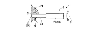
- the suture needle device 2 is used in combination with a suture needle D1, which is a curved needle, for example.
- a suture needle D2 (see FIG. 8) is attached to the suture needle D1.
- the suture needle holder 2 is connected to the sheath portion 20 that can be inserted into the body, the grip portion 30 provided at the distal end portion of the sheath portion 20, and the sheath portion 30. 20, an operation wire 40 that can move relative to the sheath portion 20 along the longitudinal axis C ⁇ b> 1, and an operation portion 50 connected to the sheath portion 20.
- the grip portion 30 side with respect to the operation portion 50 is referred to as a distal end side
- the operation portion 50 side with respect to the grip portion 30 is referred to as a proximal end side.
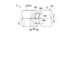
- the sheath portion 20 includes a flexible sheath 21 and a rotor 22 connected to the proximal end portion of the sheath 21.
- a flange 21 a is formed on the outer peripheral surface of the base end portion of the sheath 21 over the entire periphery.
- a key protrusion 21b is formed on a part of the outer peripheral surface of the flange 21a in the circumferential direction of the sheath portion 20 so as to protrude radially outward of the sheath portion 20 from the outer peripheral surface of the flange 21a.
- the sheath 21 is formed of a flexible material such as a coil sheath.
- the flange 21a and the key protrusion 21b are integrally formed of a metal such as stainless steel or titanium, and are fixed to the proximal end portion of the sheath 21 by welding or the like.
- the inner diameter of the large diameter portion 22b formed on the base end side of the rotor 22 is larger than the inner diameter of the small diameter portion 22a formed on the distal end side of the rotor 22 formed in a cylindrical shape. large.
- An engagement groove 22c is formed on the inner peripheral surface of the small diameter portion 22a over the entire circumference.
- a key groove 22d that extends radially outward from the bottom surface of the engagement groove 22c is formed in a part of the bottom surface of the engagement groove 22c in the circumferential direction.
- the base end portion of the large-diameter portion 22b is cut away on both sides in the radial direction across the support portion 22e to form notches (reference numerals omitted).
- the convex portion 22e is formed in a rod shape extending toward the base end side.
- a convex portion 22g protruding radially inward is provided at the base end portion of the support portion 22e.
- the convex portion 22g is formed in a columnar shape, for example.
- An engaging portion 22h is provided at a position facing the convex portion 22g on the inner peripheral surface of the base end portion of the large diameter portion 22b.
- the engaging portion 22h is formed in a rib shape extending in the circumferential direction, for example.
- the small diameter portion 22a, the large diameter portion 22b, the support portion 22e, the convex portion 22g, and the engagement portion 22h are integrally formed of a metal such as stainless steel or titanium.
- the sheath 21 is inserted into the rotor 22, the flange 21 a of the sheath 21 is engaged with the engagement groove 22 c of the rotor 22, and the key protrusion 21 b of the sheath 21 is engaged with the key groove 22 d of the rotor 22. .
- the engagement groove 22c and the flange 21a, and the key groove 22d and the key protrusion 21b are fixed by an adhesive, welding, or the like (not shown).
- the sheath 21 and the rotor 22 are integrally moved in the direction along the longitudinal axis C1 or rotated around the longitudinal axis C1.
- an operation wire 40 is inserted through the sheath 21 and the rotor 22.
- a coil spring (elastic member) 24 is disposed in the large diameter portion 22 b of the rotor 22.
- the distal end portion of the coil spring 24 is connected to a step portion (reference numeral omitted) formed between the small diameter portion 22 a and the large diameter portion 22 b of the rotor 22.
- An operation wire 40 is inserted into the coil spring 24.
- the grip portion 30 includes a grip member 31 and a grip member 32.
- the gripping member 31 is fixed to the distal end portion of the sheath 21 via the support member 33.
- the grip member 32 is rotatably supported around a pin 34 attached to the support member 33.
- the distal end portion of the operation wire 40 is connected to the proximal end portion of the gripping member 32 via a link member (not shown).
- FIG. 1 shows an open state in which the operating wire 40 is moved to the distal end side with respect to the sheath 21 and the gripping member 31 and the distal end portion of the gripping member 32 are opened apart from each other.
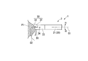
- the gripping member 32 moves to the position Q1, and the gripping member 31 and the distal end portion of the gripping member 32 are close to each other and closed. become.
- the suture needle D1 can be gripped between the gripping member 31 and the gripping member 32. That is, the operation wire 40 is connected to the gripping member 31 and the gripping member 32, and moves relative to the sheath 21 along the longitudinal axis of the sheath 21. Can be operated to open and close.
- the operation wire 40 is formed of a single wire or a stranded wire.
- a cylindrical fixing member 41 shown in FIG. 2 is attached to the proximal end portion of the operation wire 40 by brazing or the like.
- the operation unit 50 is formed in an axial shape extending along the longitudinal axis C ⁇ b> 1, and is connected to the operation unit main body 51 connected to the rotor 22 of the sheath unit 20. And a slider (traction member) 52 slidably provided along the longitudinal axis C1.
- the operation unit 50 is a so-called slider-type handle.
- the operation unit main body 51 is held by an operator.
- a plurality of tooth portions 54 are formed along the longitudinal axis C1 on the side surface 51a parallel to the longitudinal axis C1 of the operation unit main body 51. As shown in the enlarged view of FIG.
- each tooth portion 54 is formed with an orthogonal surface 54a orthogonal to the longitudinal axis C1 and an inclined surface 54b spaced from the longitudinal axis C1 toward the proximal end side. ing.
- a finger ring 55 is attached to the proximal end portion of the operation portion main body 51 (see FIG. 1).
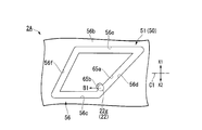
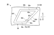
- a small diameter portion 56 having a smaller outer diameter than the proximal end side is formed at the distal end portion of the operation portion main body 51.
- a cross section of the small diameter portion 56 by a plane orthogonal to the longitudinal axis C1 is formed in a cylindrical shape.
- a flange 56 a is formed on the outer peripheral surface of the distal end portion of the small diameter portion 56 over the entire circumference.
- the small diameter portion 56 of the operation portion main body 51 is inserted into the large diameter portion 22 b of the rotor 22.
- the flange 56a of the operation portion main body 51 and the engagement portion 22h of the rotor 22 are engaged, and the small diameter portion 56 of the operation portion main body 51 and the rotor 22 slide.
- the operation part main body 51 of the operation part 50 can move with respect to the sheath part 20 in the direction along the longitudinal axis C1 and around the longitudinal axis C1.
- the outer peripheral surface 56b of the small diameter portion 56 is formed with a first groove portion 56c and a second groove portion 56d.
- the first groove 56c has a distal end and a proximal end, and extends along the longitudinal axis C1 from the distal end to the proximal end.
- the second groove portion 56d has one end connected to the base end of the first groove portion 56c, and the other end at a position away from the one end in the spiral direction around the longitudinal axis C1, and extends from one end to the other end. It is formed in a shape.
- a third groove portion 56e and a fourth groove portion 56f are formed on the outer peripheral surface 56b of the small diameter portion 56.
- the third groove portion 56e has a distal end and a proximal end, the proximal end is connected to the other end of the second groove portion, and extends along the longitudinal axis C1 from the proximal end to the distal end.
- the fourth groove portion 56f extends around the longitudinal axis C1 so as to connect the tip end of the third groove portion and the tip end of the first groove portion, and in the present embodiment, the fourth groove portion 56f formed in a spiral shape is formed. Illustrated.
- the grooves 56c and 56e are formed in a straight line.
- the length of the longitudinal axis C1 of the first groove portion 56c is equal to or less than the length of the longitudinal axis C1 of the entire plurality of tooth portions 54 (pitch of the tooth portions 54 ⁇ the number of tooth portions 54).
- the second groove portion 56d extends toward the first side (first direction) X1 around the longitudinal axis C1 as it goes toward the base end side.
- the fourth groove portion 56f extends toward the second side (second direction) X2 around the longitudinal axis C1 as it goes toward the distal end side.
- the tip of the fourth groove 56f is continuous with the tip of the first groove 56c.
- the grooves 56d and 56f are formed in a spiral shape having the longitudinal axis C1 as a spiral axis.
- the lead angle ⁇ 4 of the fourth groove portion 56f is smaller than the lead angle ⁇ 2 of the second groove portion 56d.
- the widths of the groove portions 56c, 56d, 56e, and 56f are slightly larger than the outer diameter of the convex portion 22g of the rotor 22.
- the convex portion 22g of the rotor 22 engages with the groove portions 56c, 56d, 56e, and 56f, and can move (slide) along the groove portions 56c, 56d, 56e, and 56f.
- the distal end in the first groove portion 56c is pulled by pulling the operation wire 40 with respect to the sheath 21 (operation portion main body).
- the convex portion 22g moves from the side to the base end side, and the grasping members 31 and 32 change from the open state to the closed state, and grasp the suture needle D1.
- the one end in the second groove portion 56d is moved from one end to the other end.
- the rotor 22, the sheath 21, and the grip portion 30 together with the convex portion 22g rotate together around the longitudinal axis C1 along the second groove portion 56d. That is, in a state where the suture needle D1 is grasped by the grasping members 31 and 32, the grasping portion 30 is rotated around the longitudinal axis C1 with respect to the operation portion main body 51 together with the sheath 21, and punctures the suture needle D1 into the tissue. .
- the convex portion 22g moves from the proximal end side to the distal end side in the third groove portion 56e, and the sheath 21
- the operation wire 40 moves to the distal end side
- the gripping members 31, 32 are changed from the closed state to the open state, and the suture needle D1 is released.
- the convex portion 22g moves from one end to the other end in the fourth groove portion 56f and rotates together with the convex portion 22g.
- the child 22, the sheath 21, and the grip portion 30 are integrally rotated around the longitudinal axis C ⁇ b> 1 along the fourth groove portion 56 f. That is, in a state where the gripping members 31 and 32 are opened apart from each other, the gripping portion 30 rotates together with the sheath 21 in a direction opposite to the direction of rotation in the second state.
- the proximal end portion of the coil spring 24 is connected to the distal end surface of the small diameter portion 56 of the operation portion main body 51.
- a slit 51 b is formed on the longitudinal axis C ⁇ b> 1 of the operation unit main body 51. The operation wire 40 is inserted through the slit 51b.
- a concave portion 52 a is formed on the longitudinal axis C ⁇ b> 1 of the slider 52.
- the fixing member 41 is disposed in the recess 52a, and the fixing member 41 is fixed to the base end portion of the operation wire 40 by the slider 52 by engaging with the recess 52a.
- the slider 52 is formed with a slit 52f extending along the longitudinal axis C1 shown in FIG. By inserting the operation portion main body 51 into the slit 52f, the slider 52 can slide along the longitudinal axis C1 with respect to the operation portion main body 51.
- a recess 52b is formed extending from the outer surface of the slider 52 in a direction intersecting the longitudinal axis C1.
- a finger hanging recess 52c is formed around the longitudinal axis C1.
- a button 57 is inserted into the opening 52d communicating with the outside in the recess 52b.
- a connecting plate 58 is provided on the opposite side of the opening 52d across the longitudinal axis C1 in the recess 52b of the slider 52. The connecting plate 58 is connected to the button 57.
- a tooth portion 59 is formed on the surface of the connecting plate 58 on the longitudinal axis C1 side. As shown in the enlarged view of FIG. 2, the tooth portion 59 is formed with an orthogonal surface 59a orthogonal to the longitudinal axis C1 and an inclined surface 59b spaced from the longitudinal axis C1 toward the proximal end side. .
- a coil spring 60 is disposed between the bottom surface of the recess 52 b of the slider 52 and the connecting plate 58.
- the coil spring 60 biases the connecting plate 58 toward the longitudinal axis C1.
- a ratchet mechanism 61 is configured by the plurality of tooth portions 54, the buttons 57, the connecting plate 58, the tooth portions 59, and the coil spring 60.
- the operation portion Even if the tooth portion 59 of the connecting plate 58 is in contact with the tooth portion 54 of the operation portion main body 51 by sliding the inclined surface 59b of the tooth portion 59 on the inclined surface 54b of the plurality of tooth portions 54, the operation portion.
- the slider 52 can be moved to the base end side with respect to the main body 51.
- the button 57 is moved and pushed to the position Q2 on the longitudinal axis C1 side.
- the tooth portion 54 moves to the position Q3
- the tooth portion 59 of the connecting plate 58 does not come into contact with the tooth portion 54 of the operation portion main body 51, and the slider 52 is moved toward the distal end side and the base with respect to the operation portion main body 51. It can be moved to either end.
- the tooth part 54A and tooth part 59 which are located in the most base end side among several tooth parts 54 engage. That is, the tooth portion 54 and the tooth portion 59 are engaged when the convex portion 22g is disposed in the first groove portion 56c, but the convex portion 22g is disposed in the second groove portion 56d. The tooth part 54 and the tooth part 59 are not engaged.
- the slider 52 is restricted from moving toward the distal end side with respect to the operation portion main body 51. It is allowed to move proximally.
- the slider 52 is allowed to move to either the distal end side or the proximal end side with respect to the operation portion main body 51.
- the operation wire 40 moves to the proximal end side with respect to the operation portion main body 51 and the sheath 21, and the gripping member 31 and 32 are closed.
- the operation wire 40 moves to the distal end side with respect to the operation portion main body 51 and the sheath 21, and the gripping members 31 and 32 are moved. Opened.
- the endoscope system 1 configured as described above will be described.
- a procedure for suturing a tissue that is a treatment target site formed in the stomach of a patient will be described as an example.
- the convex portion 22g is disposed in the proximal end portion of the third groove portion 56e, and the grip members 31 and 32 are kept closed.
- the insertion portion 11 of the endoscope 3 is inserted from a natural opening such as a patient's mouth, and is held in a state where the distal end surface of the insertion portion 11 is opposed to a tissue that is a treatment target site.
- the sheath portion 20 of the suture needle 2 is inserted from the proximal end portion of the channel 12 of the endoscope 3, and the grip portion 30 is projected from the distal end portion of the channel 12.
- the operator holds the operation unit 50 by passing the thumb of one hand through the finger ring 55 of the operation unit main body 51 and placing the index finger and the middle finger on the finger holding recess 52 c of the slider 52.
- the slider 52 is pushed in and the convex portion 22g is disposed at the tip end portion of the fourth groove portion 56f, that is, the tip end portion of the first groove portion 56c, the grip members 31 and 32 are opened, and the first member around the longitudinal axis C1.
- the second side (second direction) X2 Turn to the second side (second direction) X2.
- a suturing needle D1 conveyed into the stomach by a conveying means (not shown) is arranged between the grasping member 31 and the grasping member 32.
- the slider 52 is pulled back from the state in which the convex portion 22g is disposed at the tip end portion of the first groove portion 56c. Accordingly, as shown in FIGS. 7 and 8, the convex portion 22g moves to the proximal end side in the first groove portion 56c, and the operation wire 40 moves to the proximal end side with respect to the sheath portion 20, and the gripping member 31, 32 is closed and grips the suture needle D1.
- the coil spring 24 is compressed in the direction along the longitudinal axis C ⁇ b> 1 rather than the natural length state. Since the plurality of teeth 54 and the teeth 59 of the ratchet mechanism 61 are engaged, the slider 52 can be pulled back, but the slider 52 that has been pulled back cannot be pushed in.
- the surgeon pushes the suture holding needle device 2 or adjusts the direction in which the bending portion (not shown) of the insertion portion 11 of the endoscope 3 is bent, thereby changing the positional relationship between the tissue P1 and the suture needle D1. Adjust.
- the convex portion 22g moves to the proximal end side in the second groove portion 56d as shown in FIGS. 9 to 11, and the grip members 31, 32 and the sheath portion 20 are moved to the operation portion main body 51.
- the coil spring 24 is further compressed in the direction along the longitudinal axis C1, and the tissue P1 is punctured with the distal end portion of the suture needle D1.
- the proximal end side of the coil spring 24 is twisted to the first side (first direction) X1 around the longitudinal axis C1. In this way, the operator simply pulls back the slider 52, and the operation in which the grasping members 31 and 32 are closed and the suture needle D1 is grasped and the operation in which the tissue P1 is punctured with the suture needle D1 are continuously performed. Is called. Since the gripping members 31 and 32 are in the closed state when the convex portion 22g is disposed in the second groove portion 56d, the tissue P1 can be punctured with the suture needle D1 while the suture needle D1 is securely gripped. it can. When the operations of grasping the suturing needle D1 and puncturing the tissue P1 are completed, the convex portion 22g is disposed at the proximal end portion of the second groove portion 56d.
- the slider 52 is pushed in and the holding part 30 is pushed.
- the suture needle D1 can be removed from the tissue P1 by rotating the second side (second direction) X2 around the longitudinal axis C1.
- the protrusion 22g cannot be moved into the first groove 56c by the ratchet mechanism 61.
- the place where the tissue P1 is punctured with the suture needle D1 is adjusted, the slider 52 is pulled back, and the tissue P1 is punctured with the suture needle D1.
- the convex portion 22g moves in the fourth groove portion 56f to the tip side by the elastic force of the coil spring 24.
- the gripping members 31 and 32 and the sheath portion 20 rotate to the second side (second direction) X2 around the longitudinal axis C1 with respect to the operation portion main body 51. That is, the orientation of the gripping members 31 and 32 around the longitudinal axis C1 returns to the orientation when the gripping members 31 and 32 grip the suture needle D1.
- the slider 52 is pulled back as necessary, and the gripping members 31, 32 are closed as shown in FIG.
- the gripping members 31, 32, etc. rotate to the first side (first direction) X1 around the longitudinal axis C1, the suture needle D1 penetrates the tissue P1, and the suture thread D2 passes through the tissue P1. Pass through.
- the operation of releasing the suture needle D1 and the operation of returning the orientation of the grasping portion 30 are continuously performed by simply pressing the slider 52 by the surgeon so that the grasping members 31 and 32 are opened. .
- movement which pulls back and pushes the slider 52 is repeated, and the structure
- the grasping members 31 and 32 are closed to grasp the suturing needle D1.
- the operation of rotating the sheath portion 20 to the first side (first direction) X1 around the longitudinal axis C1 and puncturing the tissue P1 with the suture needle D1 is continuously performed. Therefore, the sheath portion 20 can be rotated only by pulling back the slider 52, and the operability of the slider 52 and the sheath portion 20 can be improved.
- Groove portions 56e and 56f are formed on the outer peripheral surface 56b of the operation portion main body 51.
- the operation of releasing the suture needle D1 and the operation of rotating the sheath portion 20 to the second side (second direction) X2 around the longitudinal axis C1 are continuously performed. Therefore, the sheath portion 20 can be rotated only by pushing the slider 52, and the operability of the slider 52 and the sheath portion 20 can be further improved. Since the suture needle holder 2 includes the coil spring 24, the slider 52 can be moved to the distal end side by the elastic force of the coil spring 24 without pushing the slider 52 after the slider 52 is pulled back.
- the suture needle device 2 includes the ratchet mechanism 61, so that the suture needle D1 once grasped by the grasping members 31 and 32 is not released and the puncture position of the tissue P1 by the suture needle D1 can be easily adjusted. Can do.
- the tooth portion 59 is not locked to the plurality of tooth portions 54, the convex portion 22g moves from the first groove portion 56c to the second groove portion 56d. Therefore, by the engagement of the plurality of tooth portions 54 and the tooth portions 59, the open / closed state of the grip members 31, 32 can be sensed, and the open / close operation of the grip members 31, 32 can be easily performed.
- the suture holder 2 of the present embodiment can be variously modified in its configuration as described below.
- the immersion portion 65b may be formed at the end portion on the first groove portion 56c side of the side surface 65a on the distal end side of the second groove portion 56d.
- the immersion portion 65b is recessed toward the distal end side and can accommodate at least a part of the convex portion 22g.
- an elastic force is applied to the convex portion 22g so as to move the convex portion 22g as indicated by the arrow B1 to the tip side.
- the convex part 22g is accommodated in the immersive part 65b, even if the elastic force as shown by the arrow B1 acts on the convex part 22g, the convex part 22g is difficult to come out from the immersive part 65b. Therefore, it can prevent more reliably that the convex part 22g returns in the 1st groove part 56c from the inside of the 2nd groove part 56d.
- a protrusion 65e is formed on the side surface 65d on the proximal end side of the second groove portion 56d. May be.
- the protruding portion 65e is formed so as to protrude toward the distal end side at a portion of the side surface 65d that faces the immersion portion 65b.
- the protruding portion 65e and the immersion portion 65b form a meandering portion 65f in which the second groove portion 56d meanders.
- the width of the meandering part 65f is set so that the convex part 22g can pass.
- the immersion portion 66b is located at the end portion on the second groove portion 56d side of the side surface 66a of the first side (first direction) X1 around the longitudinal axis C1 of the first groove portion 56c.
- a protrusion 66d may be formed on the side surface 66c on the second side (second direction) X2 around the longitudinal axis C1 of the first groove 56c.
- the meandering portion 66e in which the first groove portion 56c meanders is formed by the immersion portion 66b and the protruding portion 66d.
- the base end side of the coil spring 24 is twisted to the first side (first direction) X1 around the longitudinal axis C1, thereby the coil spring. 24, an elastic force acts to move the convex portion 22g to the second side (second direction) X2 around the longitudinal axis C1. For this reason, when the operator loosens the force of pulling back the slider 52, the convex portion 22g is accommodated in the recess 66f formed adjacent to the proximal end side of the protruding portion 66d on the side surface 66c of the first groove portion 56c.
- the length by which the protruding portion 66d protrudes from the side surface 66c of the first groove portion 56c is preferably longer than a certain extent.
- the convex portion 22g is accommodated in the recess 66f, and the convex portion 22g is inserted into the first groove portion 56d from the first groove portion 56d. It can prevent more reliably returning in the groove part 56c.
- the convex portion 22g can easily pass through the first groove portion 56c to the proximal end side.
- the second protrusion 66g may be formed at the end of the side surface 66c of the first groove 56c on the second groove 56d side.
- the second protrusion 66g protrudes from the side surface 66c in a semicircular shape.
- the distance L between the side surface 66a and the second protrusion 66g is slightly smaller than the outer diameter of the protrusion 22g.
- the elastic force of the coil spring 24 prevents the convex portion 22g from moving between the side surface 66a and the second protruding portion 66g to the tip side. Even if the second protrusion 66g is formed at the end of the side surface 66c of the first groove 56c on the second groove 56d side, the same effect as that of the suture needle 2A of the modified example can be obtained.
- the grooves 56e and 56f may not be formed on the outer peripheral surface 56b of the operation unit main body 51. This is because if the grooves 56c and 56d are formed on the outer peripheral surface 56b of the operation portion main body 51, the operation of grasping the suture needle D1 and puncturing the tissue P1 with the suture needle D1 can be performed once.
- the sheath 21 may be engaged with the rotor 22 on the first side (first direction) X1 and the second side (second direction) X2 around the longitudinal axis C1, and on the distal end side. It does not need to be locked to the end side.
- the elastic member is the coil spring 24, the elastic member may be rubber or the like. Further, the suture holding needle device 2 may not include the coil spring 24. This is because the surgeon may push the slider 52 and operate it.
- the sheath 21 is fixed to the rotor 22 in a state where the sheath 21 is inserted through the rotor 22, the sheath 21 may be configured to be fixed to the sheath while being inserted through the sheath.
- the endoscope 3 is assumed to include a flexible insertion portion 11. However, the endoscope may include a hard insertion portion having a bending rigidity larger than that of the softness.
- the operation unit 50 is a slider handle.
- the operation unit is a so-called inline-type handle in which one end portion of the pulling member is rotatably attached to the operation unit main body, and the base end portion of the operation wire 40 is connected to the other end portion of the pulling member. It may be. This is because the operation wire 40 can be moved in the direction along the longitudinal axis C1 with respect to the sheath portion 20 by operating the pulling member of the operation portion.
- this invention is not limited to these embodiment and its modification. Additions, omissions, substitutions, and other modifications can be made without departing from the spirit of the present invention. Further, the present invention is not limited by the above description, and is limited only by the scope of the appended claims.
- the suturing needle holder and the endoscope system according to the above-described embodiment can improve the operability of the pulling member and the sheath portion.
Landscapes
- Health & Medical Sciences (AREA)
- Life Sciences & Earth Sciences (AREA)
- Surgery (AREA)
- Heart & Thoracic Surgery (AREA)
- Engineering & Computer Science (AREA)
- Biomedical Technology (AREA)
- Nuclear Medicine, Radiotherapy & Molecular Imaging (AREA)
- Medical Informatics (AREA)
- Molecular Biology (AREA)
- Animal Behavior & Ethology (AREA)
- General Health & Medical Sciences (AREA)
- Public Health (AREA)
- Veterinary Medicine (AREA)
- Surgical Instruments (AREA)
Abstract
Priority Applications (4)
| Application Number | Priority Date | Filing Date | Title |
|---|---|---|---|
| CN201580035019.2A CN106659497B (zh) | 2014-07-03 | 2015-07-03 | 缝合持针器及内窥镜系统 |
| JP2016524609A JP6045755B2 (ja) | 2014-07-03 | 2015-07-03 | 縫合持針器及び内視鏡システム |
| EP15816008.5A EP3165175B1 (fr) | 2014-07-03 | 2015-07-03 | Porte-aiguille de suture |
| US15/382,470 US9737295B2 (en) | 2014-07-03 | 2016-12-16 | Suture-needle holder and endoscope system |
Applications Claiming Priority (2)
| Application Number | Priority Date | Filing Date | Title |
|---|---|---|---|
| JP2014-137886 | 2014-07-03 | ||
| JP2014137886 | 2014-07-03 |
Related Child Applications (1)
| Application Number | Title | Priority Date | Filing Date |
|---|---|---|---|
| US15/382,470 Continuation US9737295B2 (en) | 2014-07-03 | 2016-12-16 | Suture-needle holder and endoscope system |
Publications (1)
| Publication Number | Publication Date |
|---|---|
| WO2016002932A1 true WO2016002932A1 (fr) | 2016-01-07 |
Family
ID=55019458
Family Applications (1)
| Application Number | Title | Priority Date | Filing Date |
|---|---|---|---|
| PCT/JP2015/069276 Ceased WO2016002932A1 (fr) | 2014-07-03 | 2015-07-03 | Porte-aiguille de suture et système d'endoscope |
Country Status (5)
| Country | Link |
|---|---|
| US (1) | US9737295B2 (fr) |
| EP (1) | EP3165175B1 (fr) |
| JP (1) | JP6045755B2 (fr) |
| CN (1) | CN106659497B (fr) |
| WO (1) | WO2016002932A1 (fr) |
Cited By (2)
| Publication number | Priority date | Publication date | Assignee | Title |
|---|---|---|---|---|
| WO2021079461A1 (fr) * | 2019-10-24 | 2021-04-29 | オリンパス株式会社 | Porte-aiguille pour endoscope et procédé de manipulation d'aiguille de suture |
| JPWO2021176636A1 (fr) * | 2020-03-05 | 2021-09-10 |
Families Citing this family (7)
| Publication number | Priority date | Publication date | Assignee | Title |
|---|---|---|---|---|
| DE112018007329T5 (de) * | 2018-03-22 | 2020-12-03 | Olympus Corporation | Nadelhalter und Verfahren zu dessen Verwendung |
| US20210290224A1 (en) * | 2018-08-24 | 2021-09-23 | National Industry Information Research Institute Co., Ltd. | Grasper, needle carrier, and pinching attachment |
| WO2020152811A1 (fr) * | 2019-01-23 | 2020-07-30 | オリンパス株式会社 | Outil de traitement par énergie |
| WO2022079786A1 (fr) * | 2020-10-13 | 2022-04-21 | オリンパス株式会社 | Dispositif de traction, procédé de traction de fil de suture et méthode de suture |
| WO2022079788A1 (fr) * | 2020-10-13 | 2022-04-21 | オリンパス株式会社 | Instrument de traction, système de traction, procédé de traction de fil de suture, et procédé de suture |
| JP7697218B2 (ja) * | 2021-02-03 | 2025-06-24 | ブラザー工業株式会社 | 縫合装置 |
| US11871969B2 (en) | 2021-03-03 | 2024-01-16 | Acustitch, Llc | System and method for osseous reconstruction and repair and implant device |
Citations (4)
| Publication number | Priority date | Publication date | Assignee | Title |
|---|---|---|---|---|
| US5938668A (en) * | 1994-10-07 | 1999-08-17 | United States Surgical | Surgical suturing apparatus |
| JP2005161050A (ja) * | 2003-12-01 | 2005-06-23 | Shoshi Sho | 内視鏡用処置具 |
| JP2010036027A (ja) * | 2008-07-31 | 2010-02-18 | Olympus Medical Systems Corp | 縫合器 |
| WO2011055684A1 (fr) * | 2009-11-09 | 2011-05-12 | 学校法人帝京大学 | Porte-aiguille chirurgical |
Family Cites Families (10)
| Publication number | Priority date | Publication date | Assignee | Title |
|---|---|---|---|---|
| JP2545558Y2 (ja) * | 1990-10-23 | 1997-08-25 | ジョンソン・エンド・ジョンソンメディカル株式会社 | 深部縫合器 |
| US5458608A (en) * | 1993-06-03 | 1995-10-17 | Surgin Surgical Instrumentation Inc. | Laparoscopic instruments and methods |
| US5443479A (en) * | 1994-02-07 | 1995-08-22 | Bressi, Jr.; Thomas E. | Surgical forceps |
| WO1999005976A1 (fr) * | 1997-08-01 | 1999-02-11 | Inbae Yoon | Instrument chirurgical dote de plusieurs effecteurs terminaux capables d'etre deployes et disposes de maniere a permettre un deplacement en arc |
| US9314235B2 (en) * | 2003-02-05 | 2016-04-19 | Smith & Nephew, Inc. | Tissue anchor and insertion tool |
| CN2675055Y (zh) * | 2003-09-03 | 2005-02-02 | 王光明 | 防滑持针器 |
| JP4681961B2 (ja) * | 2005-01-14 | 2011-05-11 | オリンパスメディカルシステムズ株式会社 | 外科用処置具 |
| US20080243180A1 (en) * | 2005-01-26 | 2008-10-02 | Yen-Yue Lin | Surgery fixation forceps |
| US20090198098A1 (en) | 2008-02-01 | 2009-08-06 | Olympus Medical Systems Corp. | Endoscope treatment instrument |
| CN202568376U (zh) * | 2012-04-05 | 2012-12-05 | 王春恒 | 一种带有照明装置的阑尾荷包缝合钳 |
-
2015
- 2015-07-03 JP JP2016524609A patent/JP6045755B2/ja active Active
- 2015-07-03 CN CN201580035019.2A patent/CN106659497B/zh active Active
- 2015-07-03 EP EP15816008.5A patent/EP3165175B1/fr active Active
- 2015-07-03 WO PCT/JP2015/069276 patent/WO2016002932A1/fr not_active Ceased
-
2016
- 2016-12-16 US US15/382,470 patent/US9737295B2/en active Active
Patent Citations (4)
| Publication number | Priority date | Publication date | Assignee | Title |
|---|---|---|---|---|
| US5938668A (en) * | 1994-10-07 | 1999-08-17 | United States Surgical | Surgical suturing apparatus |
| JP2005161050A (ja) * | 2003-12-01 | 2005-06-23 | Shoshi Sho | 内視鏡用処置具 |
| JP2010036027A (ja) * | 2008-07-31 | 2010-02-18 | Olympus Medical Systems Corp | 縫合器 |
| WO2011055684A1 (fr) * | 2009-11-09 | 2011-05-12 | 学校法人帝京大学 | Porte-aiguille chirurgical |
Cited By (9)
| Publication number | Priority date | Publication date | Assignee | Title |
|---|---|---|---|---|
| WO2021079461A1 (fr) * | 2019-10-24 | 2021-04-29 | オリンパス株式会社 | Porte-aiguille pour endoscope et procédé de manipulation d'aiguille de suture |
| JPWO2021079461A1 (fr) * | 2019-10-24 | 2021-04-29 | ||
| JP7233562B2 (ja) | 2019-10-24 | 2023-03-06 | オリンパス株式会社 | 内視鏡用持針器および縫合針の操作方法 |
| US12357300B2 (en) | 2019-10-24 | 2025-07-15 | Olympus Corporation | Needle holder for endoscope and operating method of suture needle |
| JPWO2021176636A1 (fr) * | 2020-03-05 | 2021-09-10 | ||
| WO2021176636A1 (fr) * | 2020-03-05 | 2021-09-10 | オリンパス株式会社 | Porte-aiguille pour endoscope, et procédé de suture endoscopique |
| CN115209817A (zh) * | 2020-03-05 | 2022-10-18 | 奥林巴斯株式会社 | 内窥镜用持针器及内窥镜下缝合方法 |
| JP7349553B2 (ja) | 2020-03-05 | 2023-09-22 | オリンパス株式会社 | 内視鏡用持針器 |
| CN115209817B (zh) * | 2020-03-05 | 2025-08-22 | 奥林巴斯株式会社 | 内窥镜用持针器 |
Also Published As
| Publication number | Publication date |
|---|---|
| JP6045755B2 (ja) | 2016-12-14 |
| CN106659497B (zh) | 2019-06-18 |
| US9737295B2 (en) | 2017-08-22 |
| CN106659497A (zh) | 2017-05-10 |
| US20170095249A1 (en) | 2017-04-06 |
| JPWO2016002932A1 (ja) | 2017-04-27 |
| EP3165175A1 (fr) | 2017-05-10 |
| EP3165175A4 (fr) | 2018-01-03 |
| EP3165175B1 (fr) | 2019-03-06 |
Similar Documents
| Publication | Publication Date | Title |
|---|---|---|
| JP6045755B2 (ja) | 縫合持針器及び内視鏡システム | |
| US10835220B2 (en) | Self-articulating joint for a minimally invasive surgical apparatus | |
| JP4855765B2 (ja) | 内視鏡用治療装置 | |
| CN106488747B (zh) | 手术用器具 | |
| JP5500715B2 (ja) | 医療用開閉式鉗子 | |
| US20100063354A1 (en) | Manipulation mechanism and medical device instrument | |
| JPWO2016021268A1 (ja) | 手術用器具及び組織切離ユニット | |
| JP2015061669A (ja) | 縫合器 | |
| JP6913218B2 (ja) | 内視鏡用鉗子の製造方法 | |
| JP5784856B2 (ja) | 縫合器 | |
| JP2009183690A (ja) | 内視鏡用処置具 | |
| JP6184639B2 (ja) | 縫合器 | |
| JP4481029B2 (ja) | 内視鏡用処置具 | |
| JPWO2018163410A1 (ja) | ガイドワイヤ把持具 | |
| EP2796096A1 (fr) | Raccord médical | |
| JP6996000B2 (ja) | 内視鏡システム | |
| JPWO2017109923A1 (ja) | 結紮デバイス | |
| JP2010207340A (ja) | 内視鏡案内管装置 | |
| JP5266358B2 (ja) | 持針器 | |
| US11612390B2 (en) | Suturing closure scope with alternative needle orientation | |
| JP7077964B2 (ja) | 縫合装置 | |
| EP3643251B1 (fr) | Dispositif de suture | |
| JP7349553B2 (ja) | 内視鏡用持針器 | |
| WO2020149408A1 (fr) | Instrument de traitement endoscopique et outil auxiliaire pour outil de traitement endoscopique | |
| JP2010194221A (ja) | 内視鏡案内管装置 |
Legal Events
| Date | Code | Title | Description |
|---|---|---|---|
| 121 | Ep: the epo has been informed by wipo that ep was designated in this application |
Ref document number: 15816008 Country of ref document: EP Kind code of ref document: A1 |
|
| ENP | Entry into the national phase |
Ref document number: 2016524609 Country of ref document: JP Kind code of ref document: A |
|
| NENP | Non-entry into the national phase |
Ref country code: DE |
|
| REEP | Request for entry into the european phase |
Ref document number: 2015816008 Country of ref document: EP |
|
| WWE | Wipo information: entry into national phase |
Ref document number: 2015816008 Country of ref document: EP |