EP3165652B1 - Procédé de tricotage et machine à tricoter circulaire - Google Patents
Procédé de tricotage et machine à tricoter circulaire Download PDFInfo
- Publication number
- EP3165652B1 EP3165652B1 EP16195821.0A EP16195821A EP3165652B1 EP 3165652 B1 EP3165652 B1 EP 3165652B1 EP 16195821 A EP16195821 A EP 16195821A EP 3165652 B1 EP3165652 B1 EP 3165652B1
- Authority
- EP
- European Patent Office
- Prior art keywords
- needle
- butt
- jack
- cam
- welting
- Prior art date
- Legal status (The legal status is an assumption and is not a legal conclusion. Google has not performed a legal analysis and makes no representation as to the accuracy of the status listed.)
- Active
Links
Images


Classifications
-
- D—TEXTILES; PAPER
- D04—BRAIDING; LACE-MAKING; KNITTING; TRIMMINGS; NON-WOVEN FABRICS
- D04B—KNITTING
- D04B15/00—Details of, or auxiliary devices incorporated in, weft knitting machines, restricted to machines of this kind
- D04B15/32—Cam systems or assemblies for operating knitting instruments
-
- D—TEXTILES; PAPER
- D04—BRAIDING; LACE-MAKING; KNITTING; TRIMMINGS; NON-WOVEN FABRICS
- D04B—KNITTING
- D04B1/00—Weft knitting processes for the production of fabrics or articles not dependent on the use of particular machines; Fabrics or articles defined by such processes
- D04B1/10—Patterned fabrics or articles
- D04B1/102—Patterned fabrics or articles with stitch pattern
-
- D—TEXTILES; PAPER
- D04—BRAIDING; LACE-MAKING; KNITTING; TRIMMINGS; NON-WOVEN FABRICS
- D04B—KNITTING
- D04B15/00—Details of, or auxiliary devices incorporated in, weft knitting machines, restricted to machines of this kind
- D04B15/66—Devices for determining or controlling patterns ; Program-control arrangements
- D04B15/68—Devices for determining or controlling patterns ; Program-control arrangements characterised by the knitting instruments used
-
- D—TEXTILES; PAPER
- D04—BRAIDING; LACE-MAKING; KNITTING; TRIMMINGS; NON-WOVEN FABRICS
- D04B—KNITTING
- D04B15/00—Details of, or auxiliary devices incorporated in, weft knitting machines, restricted to machines of this kind
- D04B15/66—Devices for determining or controlling patterns ; Program-control arrangements
- D04B15/82—Devices for determining or controlling patterns ; Program-control arrangements characterised by the needle cams used
Definitions
- the present invention relates to a knitting method and a circular knitting machine, like various jacquard machines.
- Jacquard machines and the like for performing semi-jacquard knitting or jacquard knitting in circular knitting machines include a needle selector that performs needle selection. Needle selection involves switching knitting tools such as needles and sinkers between an operation state and a non-operation state, thereby changing the routes of the knitting tools. The routes of the knitting tools are changed by the needle selector, and, in the case of needles, needle routes may be one selected mainly from those for 3-position knitting structures consisting of knit, tuck, and welt, and knitting is thus performed.
- an electromagnetic needle selector that is a combination of an electromagnetic actuator, a selecting jack, and a rocking piece, for example, as shown in JP H9-111621A .
- a needle selector using a piezoelectric element that is a combination of a multi-stage piezoelectric actuator and a patterning jack for example, as shown in JP H6-94619B
- a mechanical needle selector using a multi-stage peg holder instead of a multi-stage piezoelectric actuator for example, as shown in JP S50-58347A
- the needle selecting methods using these electrical and mechanical needle selectors make it possible to select any one of knit, tuck, and welt for each needle.
- the needle selection is based on the principle that, at an entrance portion of a cam disposed at each feeder where a yarn is fed to a needle, first a selection is made as to whether a needle that moves due to rotation of a knitting machine is to be raised or to be kept at its current position, and, if it is determined that the needle is to be raised, the needle is raised to a position around the center of the cam, and before the needle reaches a yarn feeding position, a selection is made as to whether the needle is to be further raised or to be kept at its current position.
- the needle in the case of knit, the needle is first raised, then further raised, and receives a fed yarn.
- the needle In the case of tuck, the needle is first raised, is then kept at its current position, and receives a fed yarn.
- the needle In the case of welt, the needle is kept at the first position. Subsequently, as guided by the cam, the needles at the knit and tuck positions are lowered, after which all needles including the needle selected for welting perform stitching and are returned to their original positions so as to be placed into the next feeder.
- the selecting mechanism used is such that when raising a needle, a cam is caused to guide a butt of the needle and raise the needle, and, when keeping a needle at its current position, the needle or a jack provided on the lower portion of the needle is pushed in a direction that is perpendicular to the rotational direction of a cylinder and the like of the knitting machine to detach the butt from the cam, and thus guidance by the cam is deactivated and the needle is kept at its current position.
- Needle selection for tucking may not be performed depending on the machine specifications, but various jacquard machines select a knitting structure for each needle by performing needle selection once or twice before the needle reaches a yarn feeding position, making jacquard or semi-jacquard knitting possible.
- knitting structures are selected according to needle selection prior to feeding a yarn.
- needles for knitting and tucking that received a fed yarn have to perform stitching, and thus the cam structure is such that all needles also including needles for welting are uniformly lowered as guided by the cam and perform stitching, after which the needles return to their initial height and are placed into the next feeder, that is, needles for welting also perform stitching as in the case of needles for knitting and tucking.
- needles for welting do not receive a fed yarn, and thus they do not necessarily have to perform stitching.
- the welt stitching is a problem that needs to be solved in order to improve the quality.
- the welt stitching is more likely to cause breakage in yarn or filaments and affects the quality of knitted fabrics.
- the welt stitching is more likely to cause breakage in the yarn or filaments. Since an old loop in the hook of a needle selected for welting has already been stitched and its size has been determined, if a stitch at a size that is the same as or greater than the determined size is performed in a subsequent welt, the load on the old loop is large.
- the present invention is directed to a knitting method according to claim 1.
- Examples of the knitting member include a cylinder and a dial
- needle selection methods may be methods using electrical devices such as an electromagnetic needle selector or a multi-stage piezoelectric actuator, mechanical devices such as a multi-stage peg holder, or the like.
- Examples of the deactivation method include mechanical deactivation methods using a fixing member such as a projection or a multi-stage peg holder, electrical deactivation methods by needle selection using an electrical needle selector such as an electromagnetic needle selector or a multi-stage piezoelectric actuator, and the like.
- the present invention is directed to a knitting method using a needle selector for selecting needles by acting on either the needles or jacks, each needle and a jack corresponding thereto being engageable with each other and being inserted in the same needle groove, on a knitting member including needle grooves in a circular knitting machine, wherein each needle selected for welting or a butt of a jack corresponding thereto is detached from a cam for performing stitching, to after a stitch position, so that guidance by the cam is deactivated.
- the needle selected for welting or the jack corresponding thereto is not guided by the cam for performing stitching because the butt has been detached from the cam at the stitch position, and the needle does not perform stitching, and thus the load on old loops generated by performing stitching can be suppressed, and breakage and overlapping of yarns and filaments can be suppressed.
- the needle or the butt of the jack corresponding thereto is detached from the cam for performing stitching at the time of needle selection for welting and the butt is once returned to the cam after needle selection for welting and is then detached again to after the stitch position.
- the stitch position refers to the lowest position in a cam race for drawing in a fed yarn in a lateral direction, which is a rotational direction of the knitting machine.
- the upper-lower relationship is such that the hook direction of a needle is set to the upper direction and the tail direction of the needle on the opposite side is set to the lower direction.
- the height direction is set to the upper-lower direction.
- the needle selected for welting or the butt of the jack corresponding thereto is detached from the cam for performing stitching, at a position that is immediately before the stitch position and that is preferably at a height for welting. Accordingly, the needle for welting moves completely laterally without being lowered, and breakage and overlapping of yarns and filaments can be suppressed without applying a load on the loops. It will be appreciated that any position higher than the stitch position may be included in the scope of the present invention, even if it is not the height for welting.
- the needle selected for welting or the jack corresponding thereto is pushed in a direction opposite from the cam so that the butt is detached from the cam.
- the jack itself may be pushed by directly pushing the butt of the jack with a peg, or the jack may be indirectly pushed by pushing the butt of the second jack with a peg, the second jack being a jack that is inserted in the same groove as the above-described jack and is provided so as to be capable of being in contact with the jack.
- the peg it is also possible to use a projection member that is provided on a route where only the above-described jack or the second jack corresponding to the needle selected for welting passes, and that uniformly pushes the jack or the second jack.
- the peg may be electrically controlled as to whether or not to push the butt, or the peg may be a mechanical device that is set before the circular knitting machine operating. Accordingly, the needle or the butt of the jack engaged with the needle is detached from the cam for performing stitching, and thus guidance by the cam to the stitch position can be deactivated.
- the present invention is directed to a circular knitting machine according to claim 8.
- the needle selected for welting or the butt of the jack corresponding thereto is detached from the cam for performing stitching at the stitch position by the deactivation means, and thus guidance by the cam to the stitch position can be deactivated.
- the deactivation means operates when a butt of the needle is at a position that is immediately before the stitch position and that is preferably at a height for welting. Accordingly, the needle for welting moves completely laterally without being lowered, and breakage and overlapping of yarns and filaments can be suppressed without applying a load on the loops. It will be appreciated that any means that operates at a position higher than the stitch position may be included in the scope of the present invention even if it is not at the height for welting.
- the position at which the deactivation means is provided is not limited to a position facing the needle or the jack, and may also be a position facing a second jack that is inserted in the same groove as the above-described jack and is provided so as to be capable of being in contact with the jack. Accordingly, the deactivation means is not limited to a means that directly acts on the needle or the jack, and may also be a means that indirectly acts on the jack by acting on the second jack.
- the deactivation means directly or indirectly pushes the needle or the jack.
- the jack itself may be pushed by directly pushing the butt of the jack with a peg, or the jack may be indirectly pushed by pushing the butt of the second jack with a peg.
- the peg it is also possible to use a projection member that is provided on a route where only the above-described jack or the second jack corresponding to the needle selected for welting passes, and that uniformly pushes the jack or the second jack.
- the peg may be electrically controlled as to whether or not to be at a position for pushing the butt, or the peg may be a mechanical device that is set before the circular knitting machine operating. Accordingly, the needle or the butt of the jack engaged with the needle is detached from the cam for performing stitching, and thus guidance by the cam can be deactivated.
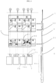
- FIG. 1 shows a front view of a cam holder of a knitting machine in Example 1 of the present invention, and a side view of a needle and jacks corresponding thereto.
- a needle 1, an intermediate jack 2 that is provided on the lower portion of the needle 1 so as to be engaged with and move in one piece with the needle 1, and a selecting jack 3 that is provided on the lower portion of the intermediate jack 2 so as to be capable of being in contact with the intermediate jack 2, are inserted in the same needle groove provided on a cylinder, which is a knitting member of a circular knitting machine.
- cams are provided so as to face the needle 1 and butts of the intermediate jack 2 via a cam holder 4.
- the intermediate jack 2 has upper and lower butts 22 and 21, and a stitch cam 41 for performing stitching and a jack raising cam 42 for raising a jack are alternately provided as cams facing the lower butt 21, along the rotational direction of the knitting machine.
- a structure is employed in which the lower butt 21 is lowered as guided by the stitch cam 41, and the intermediate jack 2 and the needle 1 engaged therewith are also lowered, so that stitching is performed.
- the cams facing the needle 1 and the upper butt 22 are not provided with a stitch portion, and the corresponding portion has a structure whereby lateral movement occurs at a welt position.
- the cam race of the jack raising cam 42 has a knit route, and is further provided with a groove at the welt position from a portion after first raising the lower butt 21 in the jack raising cam 42 to an end of the jack raising cam 42, so that, if the butt is detached from the cam at that first portion, the welt route can be traced.
- the portion where the intermediate jack 2 and the selecting jack 3 are in contact with each other is set such that the intermediate jack 2 is positioned on the inner side and the selecting jack 3 is positioned on the outer side with respect to the rotational direction of the knitting machine, and, when the selecting jack 3 is pushed to the inner side, the intermediate jack 2 is pushed by the selecting jack 3 and is also pushed to the inner side.
- an electromagnetic actuator 51 and a cam are provided so as to face the selecting jack 3 via an actuator holder 5.
- the selecting jack 3 has a push butt 31 at a position that is lower than the contact position with the intermediate jack 2 disposed on the upper portion of the selecting jack 3, and that is slightly higher than the center of the entire selecting jack 3, has a middle butt 32 at a position that is lower than the push butt 31, and is further provided with a rocking piece 33 at a position that is lower than the middle butt 32 and that is slightly lower than the center of the entire selecting jack 3.
- a push cam 52 including projections 521 and 522 is provided at a position that is higher than the push butt 31 and that is not in contact with the push butt 31, so as to face the selecting jack 3.
- the positional relationship is set such that the push butt 31 is not in contact with any projections in a usual state, but, when the selecting jack 3 is raised, the push butt 31 is brought into contact with the projections 521 and 522.
- the electromagnetic actuator 51 is provided so as to face the rocking piece 33.
- FIG. 2(a) is a cross-sectional view of the knitting machine at a position 1 in FIG. 1
- FIG. 2(b) is a cross-sectional view of the knitting machine at a position 2 in FIG. 1
- FIG. 2(c) is a cross-sectional view of the knitting machine at a position 1' in FIG. 1
- FIG. 2(d) is a cross-sectional view of the knitting machine at a position 2' in FIG. 1 .
- This example will describe needle selection from two positions consisting of knit and welt.
- the needle selection process is such that, in the case of welt, when a needle selection data signal is received, the electromagnetic actuator operates to draw in a lower portion 331 of the rocking piece 33, so that, as shown in FIG.
- the projection 522 is provided at the stitch position of the push cam 52. Accordingly, as shown in FIG. 2(d) , the selecting jack 3 corresponding to the needle 1 selected for welting moves to the stitch position while maintaining the raised state, after which the push butt 31 is uniformly pushed by the projection 522, the lower butt 21 of the intermediate jack 2 is detached from the stitch cam 41, and thus the guiding of the needle 1 to stitching is avoided, and the needle can move laterally while maintaining the welt position. Accordingly, the needle selected for welting avoids being used for stitching. On the other hand, as shown in FIG.
- This example describes the configuration of needle selection from two positions consisting of knit and welt.
- the projection 522 is merely provided at the stitch position, but it is also possible to apply a configuration in which a needle selector is provided in front of the projection 522, all selecting jacks 3 are temporarily lowered by middle cams 54 facing the middle butts 32 before reaching the needle selector, after which a needle first selected for welting is again selected by the needle selector, and the selecting jack 3 is again raised so that the push butt 31 is pushed by the projection 522 at the stitch position, and the needle selected for welting does not perform stitching and is kept at the welt position.
- this configuration if needle selection from knit and tuck is performed by providing an actuator also at a portion where needle selection is to be performed from knit and tuck, needle selection from three positions consisting of knit, tuck, and welt becomes possible.
- the selecting jack is raised in the case of needle selection for welting, and the selecting jack is caused to move laterally without being raised in the case of needle selection for knitting, but the opposite configuration is also possible.
- a projection is provided at the stitch position and the settings are made such that a needle selected for welting or a butt of a jack corresponding thereto is positioned at a height where the projection is provided and a needle selected for knitting or a butt of a jack corresponding thereto is positioned at a height that is different from the height where the projection is provided, after the needle selected for welting or the jack corresponding thereto moves to the stitch position, the push butt is uniformly pushed by the projection so that the lower butt can be detached from the cam, and the needle selected for welting avoids being used for stitching.
- FIG. 3 shows a front view of a cam holder of a knitting machine in Example 2 of the present invention, and a side view of a needle and jacks corresponding thereto.
- a patterning jack 6 is used instead of the selecting jack 3 of Example 1.
- the patterning jack 6 is provided with a patterning butt 61 including several to several tens of vertically arranged butts, and a multi-stage piezoelectric actuator 7 including a peg 71 corresponding to each butt position of the patterning butt 61 is provided so as to face the patterning butt 61.
- FIG. 4(a) is a cross-sectional view of the knitting machine at a position 1 in FIG. 3
- FIG. 4(b) is a cross-sectional view of the knitting machine at a position 2 in FIG. 3
- FIG. 4(c) is a cross-sectional view of the knitting machine at a position 3 in FIG. 3
- FIG. 4(d) is a cross-sectional view of the knitting machine at a position 1' in FIG. 3
- FIG. 4(e) is a cross-sectional view of the knitting machine at a position 3' in FIG. 3 .
- the needle selection process is such that when a needle selection data signal is received, the peg 71 of the multi-stage piezoelectric actuator 7 operates, and thus if the peg 71 is activated as shown in FIG. 4(d) , the peg 71 is horizontally oriented to be brought into contact with the patterning butt 61 and pushes the patterning butt 61 so that the patterning jack 6 is pushed accordingly and the intermediate jack 2 is also pushed, and the lower butt 21 is detached from the cam. On the other hand, if the peg 71 is deactivated as shown in FIG. 4(a) , the peg 71 is oriented downward to pass under the patterning butt 61 so that the lower butt 21 is not detached from the cam.
- the multi-stage piezoelectric actuator 7 is provided not only at a first needle selection position where needle selection is performed between knit & tuck and welt, but also at a second needle selection position where needle selection is performed between knit and tuck, and a third needle selection position, which is a stitch position where needle selection is performed so as to prevent a needle selected for welting from performing stitching.
- the peg 71 is activated as shown in FIG. 4(d) for a needle selected for welting, and is deactivated as shown in FIG. 4(a) for a needle selected for knitting or tucking.
- the second needle selection position if the lower butt 21 corresponding to the needle 1 that has been raised to the tuck position as guided by the cam as a result of the needle selection at the first needle selection position is detached from the cam at the tuck position, the needle moves laterally while maintaining that position, and thus a tuck is made.
- a peg 72 is activated as shown in FIG.
- a multi-stage piezoelectric actuator 70 is provided instead of the projection 522 at the stitch position of Example 1, where a peg 701 is activated only for a needle selected for welting and pushes the patterning butt 61, so that the lower butt 21 is detached from the cam, and the needle selected for welting avoids being used for stitching.
- a needle selected for knitting or tucking is lowered as guided by the stitch cam 41 and performs stitching.
- 3-position knitting consisting of knit, tuck, and welt can be performed such that only a needle selected for welting does not perform stitching and moves laterally while maintaining the welt position, whereas a needle selected for knitting or tucking performs stitching.
- a multi-stage piezoelectric actuator is used, but it may be replaced by a multi-stage peg holder. Accordingly, a semi-jacquard pattern can be knitted in which no pattern change is performed while the knitting machine is operating.
Landscapes
- Engineering & Computer Science (AREA)
- Textile Engineering (AREA)
- Knitting Machines (AREA)
- Knitting Of Fabric (AREA)
Claims (15)
- Procédé de tricotage réalisé en sélectionnant des aiguilles (1), insérées dans des rainures à aiguilles, sur un cylindre ou un cadran à aiguilles comprenant les rainures à aiguilles et une came (41) pour effectuer le point dans une machine à tricoter circulaire,dans lequel seules les aiguilles (1), sélectionnées pour le tricotage, et les aiguilles (1), sélectionnées pour le guillochage, effectuent le point, et les aiguilles (1), sélectionnées pour le bordage, sont empêchées d'effectuer le point par un processus de désactivation,caractérisé en ce que ledit processus de désactivation consiste à désactiver le guidage des aiguilles (1) par la came (41) vers une position de point, qui est la position la plus basse dans une course de la came, depuis immédiatement avant la position de point jusqu'après la position de point.
- Procédé de tricotage selon la revendication 1,
dans lequel le processus de désactivation comprend un processus de désactivation mécanique utilisant un élément de fixation tel qu'une saillie (522) ou un support de cheville à plusieurs étages. - Procédé de tricotage selon la revendication 1,
dans lequel le processus de désactivation comprend un processus de désactivation électrique utilisant un sélecteur d'aiguilles électrique. - Procédé de tricotage selon la revendication 1, utilisant un sélecteur d'aiguilles pour sélectionner les aiguilles (1) en agissant soit sur les aiguilles (1), soit sur les platines (2 ; 3 ; 6), chaque aiguille (1) et une platine (2) correspondante pouvant être engagées l'une dans l'autre et étant insérées dans la même rainure à aiguilles, sur le cylindre ou le cadran à aiguilles,
dans lequel un talon de chaque aiguille (1), sélectionnée pour le bordage, ou un talon (21) d'une platine (2) correspondante est détaché depuis la came (41) pour effectuer le point, de sorte que le guidage du talon par la came (41) est désactivé. - Procédé de tricotage selon la revendication 4,
dans lequel, après la sélection des aiguilles pour le bordage, le talon (21) est renvoyé une fois à la came (41) avant d'atteindre la position de point, suite à quoi le talon de l'aiguille (1), sélectionnée pour le bordage, ou le talon (21) de la platine (2) correspondante est à nouveau détaché depuis la came (41) après la position de point. - Procédé de tricotage selon la revendication 4 ou 5,
dans lequel le talon de l'aiguille (1), sélectionnée pour le bordage, ou le talon (21) de la platine (2) correspondante est détaché depuis la came (41) pour effectuer le point, à une position qui est à une hauteur pour le bordage, de telle sorte que l'aiguille (1) pour le bordage se déplace complètement latéralement sans être abaissée. - Procédé de tricotage selon l'une des revendications 4 à 6,
dans lequel l'aiguille (1), sélectionnée pour le bordage, ou la platine (2) correspondante est poussée dans une direction opposée à la came (41), de telle sorte que le talon (21) est détaché depuis la came (41). - Machine à tricoter circulaire, comprenant un mécanisme de tricotage et un cylindre ou cadran à aiguilles comportant des rainures à aiguilles, des aiguilles (1) logées respectivement dans les rainures à aiguilles, des platines (2 ; 3 ; 6) dont chacune peut être engagée avec une aiguille correspondante et est insérée dans la même rainure que l'aiguille (1), et un sélecteur d'aiguilles pour sélectionner les aiguilles (1) en agissant soit sur les aiguilles (1), soit sur les platines (2 ; 3 ; 6),
caractérisée en ce que le mécanisme de tricotage comprend un moyen de désactivation pour détacher le talon de chaque aiguille (1), sélectionnée pour le bordage, ou le talon (21) d'une platine (2) correspondante depuis une came (41) pour effectuer le point, depuis immédiatement avant une position de point, qui est la position la plus basse dans une course de la came, jusqu'après la position de point. - Machine à tricoter circulaire selon la revendication 8,
dans laquelle le moyen de désactivation fonctionne lorsqu'un talon de l'aiguille (1) se trouve dans une position qui est à une hauteur pour le bordage. - Machine à tricoter circulaire selon la revendication 8 ou 9,
dans laquelle le moyen de désactivation pousse directement ou indirectement l'aiguille (1) ou la platine (2 ; 3 ; 6). - Machine à tricoter circulaire selon l'une des revendications 8 à 10,dans laquelle la platine (2 ; 3 ; 6) est constituée d'une première platine (2) qui peut être engagée avec l'aiguille (1) et d'une seconde platine (3 ; 6) qui peut être en contact avec la première platine (2) et qui est prévue pour faire face au moyen de désactivation,la seconde platine (3 ; 6) est directement poussée par le moyen de désactivation, etla première platine (2) est poussée en correspondance indirectement de telle sorte qu'un talon (21) de la première platine (2) est détaché depuis la came (41) pour effectuer le point.
- Machine à tricoter circulaire selon l'une des revendications 8 à 11,dans laquelle une saillie (522) est prévue comme moyen de désactivation,le talon de chaque aiguille (1), sélectionnée pour le bordage, ou un talon (31 ; 32) d'une platine (3) correspondante est positionné à une hauteur où se trouve la saillie (522),le talon de chaque aiguille (1), sélectionnée pour le tricotage, ou le talon (21) d'une platine (2) correspondante est positionné à une hauteur différente de la hauteur où se trouve la saillie (522), etune fois que l'aiguille (1), sélectionnée pour le bordage, ou la platine (2 ; 3) correspondante est déplacée jusqu'à la position de point, le talon (31 ; 32) est poussé uniformément par la saillie (522), de telle sorte que le talon (21) est détaché depuis la came (41).
- Machine à tricoter circulaire selon l'une des revendications 8 à 11,dans laquelle une saillie (522) est prévue comme moyen de désactivation, un sélecteur d'aiguilles électromagnétique est prévu avant la position de point,chaque aiguille (1), sélectionnée pour le bordage, est à nouveau sélectionnée avant la position de point,le talon de l'aiguille (1), sélectionnée pour le bordage, ou le talon (31 ; 32) d'une platine (3) correspondante est positionné à une hauteur où se trouve la saillie (522),d'autres talons d'aiguilles (1) ou talons (21 ; 22) de platines (2) correspondantes sont positionnés à une hauteur différente de la hauteur où se trouve la saillie (522), etune fois que l'aiguille (1), sélectionnée pour le bordage, ou la platine (2) correspondante est déplacée à la position de point, le talon (31 ; 32) est poussé uniformément par la saillie (522), de telle sorte que le talon (21) est détaché depuis la came.
- Machine à tricoter circulaire selon l'une des revendications 8 à 11,dans laquelle un actionneur piézoélectrique à plusieurs étages (70) est prévu comme moyen de désactivation,chaque aiguille (1), sélectionnée pour le bordage, ou une platine (2 ; 6) correspondante est à nouveau sélectionnée avant la position de point, etle talon de l'aiguille (1), sélectionnée pour le bordage, ou le talon (61) de la platine (6) correspondante est poussé par une cheville (701) de l'actionneur piézoélectrique à plusieurs étages (70), de telle sorte que le talon (21) est détaché depuis la came (41).
- Machine à tricoter circulaire selon l'une des revendications 8 à 11,dans laquelle un support de cheville à plusieurs étages est prévu comme moyen de désactivation,chaque aiguille (1), sélectionnée pour le bordage, ou une platine (2 ; 6) correspondante est à nouveau sélectionnée avant la position de point, etle talon de l'aiguille (1), sélectionnée pour le bordage, ou le talon (61) de la platine (6) correspondante est poussé par une cheville (701) du support de cheville à plusieurs étages, de telle sorte que le talon (21) est détaché depuis la came (41).
Applications Claiming Priority (1)
| Application Number | Priority Date | Filing Date | Title |
|---|---|---|---|
| JP2015219423A JP2017089043A (ja) | 2015-11-09 | 2015-11-09 | 丸編機の編成方法及び編成機構並びにその丸編機 |
Publications (2)
| Publication Number | Publication Date |
|---|---|
| EP3165652A1 EP3165652A1 (fr) | 2017-05-10 |
| EP3165652B1 true EP3165652B1 (fr) | 2024-05-29 |
Family
ID=57208170
Family Applications (1)
| Application Number | Title | Priority Date | Filing Date |
|---|---|---|---|
| EP16195821.0A Active EP3165652B1 (fr) | 2015-11-09 | 2016-10-26 | Procédé de tricotage et machine à tricoter circulaire |
Country Status (4)
| Country | Link |
|---|---|
| EP (1) | EP3165652B1 (fr) |
| JP (1) | JP2017089043A (fr) |
| CN (1) | CN106995972B (fr) |
| TW (1) | TWI746478B (fr) |
Families Citing this family (3)
| Publication number | Priority date | Publication date | Assignee | Title |
|---|---|---|---|---|
| CN107841823B (zh) * | 2017-09-12 | 2023-09-15 | 浙江华诗秀新材料科技有限公司 | 外包型针织机提花接力针及组合式提花针组件 |
| CN108265381B (zh) * | 2018-03-07 | 2019-07-12 | 石狮市宝翔针织机械有限公司 | 一种电脑提花圆纬机及其添纱提花工艺 |
| CN116949658A (zh) * | 2023-07-31 | 2023-10-27 | 诸暨镭尔福机械科技有限公司 | 袜机中提花针的使用方法 |
Family Cites Families (12)
| Publication number | Priority date | Publication date | Assignee | Title |
|---|---|---|---|---|
| JPS5417867B2 (fr) | 1973-09-21 | 1979-07-03 | ||
| GB1475560A (en) * | 1974-10-04 | 1977-06-01 | Terrot Soehne & Co C | Multifeed circular knitting machine |
| JPS63211348A (ja) * | 1987-02-27 | 1988-09-02 | 株式会社 福原精機製作所 | 丸編機の選針装置 |
| JPH0694619B2 (ja) | 1988-10-05 | 1994-11-24 | ワツクデータサービス株式会社 | 編機用選針装置 |
| DE3927815C2 (de) * | 1989-08-23 | 1999-12-23 | Sipra Patent Beteiligung | Plüsch- oder Florstrickware und Rundstrickmaschine zu deren Herstellung |
| JP3178751B2 (ja) * | 1993-01-21 | 2001-06-25 | 株式会社福原精機製作所 | ダブルニット編地、およびその製造装置および方法 |
| JPH08199453A (ja) * | 1995-01-13 | 1996-08-06 | Fukuhara Seiki Seisakusho:Kk | 編機の柄出し装置 |
| JP3576664B2 (ja) | 1995-10-09 | 2004-10-13 | 株式会社福原精機製作所 | 編機用電磁選択装置及びこれを有する編みツール制御装置 |
| DE19545770A1 (de) * | 1995-12-07 | 1997-07-03 | Schmidt Ursula Dorothea | Durch Fadenflottungen gemusterte Plattierware und Verfahren zu deren Herstellung auf Rundstrickmaschinen |
| CN1563537A (zh) * | 2004-03-25 | 2005-01-12 | 江南大学 | 仿烂花效应针织绒头织物的编织方法 |
| JP4944015B2 (ja) * | 2005-03-25 | 2012-05-30 | 株式会社島精機製作所 | 横編機における筒状編地の編成方法及び横編機 |
| CN104328594B (zh) * | 2014-11-24 | 2016-07-27 | 西安工程大学 | 采用电磁选针的五功位电脑横机编织机构 |
-
2015
- 2015-11-09 JP JP2015219423A patent/JP2017089043A/ja active Pending
-
2016
- 2016-10-26 EP EP16195821.0A patent/EP3165652B1/fr active Active
- 2016-11-07 TW TW105136075A patent/TWI746478B/zh active
- 2016-11-08 CN CN201610982719.9A patent/CN106995972B/zh active Active
Also Published As
| Publication number | Publication date |
|---|---|
| CN106995972B (zh) | 2021-04-20 |
| EP3165652A1 (fr) | 2017-05-10 |
| JP2017089043A (ja) | 2017-05-25 |
| CN106995972A (zh) | 2017-08-01 |
| TW201723259A (zh) | 2017-07-01 |
| TWI746478B (zh) | 2021-11-21 |
Similar Documents
| Publication | Publication Date | Title |
|---|---|---|
| US7536879B2 (en) | Method for knitting a double jersey knit fabric on a double jacquard, double jersey circular knitting machine and double jersey knit fabric knitted by such a method | |
| JP2021021163A (ja) | 編糸の位置が変更可能な緯編機編成構造 | |
| EP2372002B1 (fr) | Machine à tricoter dotée d'aiguilles à clapet et dépourvue de platines d'abattage | |
| KR100264766B1 (ko) | 양면 환편기에 있어서의 선침 장치 | |
| EP3983587B1 (fr) | Métier à tricoter circulaire et méthode pour déplacer les aiguilles d'un métier à tricoter circulaire | |
| SG126717A1 (en) | Circular knitting machine for the production of plush fabrics | |
| EP3165652B1 (fr) | Procédé de tricotage et machine à tricoter circulaire | |
| EP2568066A2 (fr) | Procédé pour la formation de rangées initiales d'un tricot | |
| CN110387636B (zh) | 用于制造金银丝针织物的针织横机和方法 | |
| US3293887A (en) | Sinker arrangement and control means for circular knitting machine | |
| US3614877A (en) | Compound stitch cam for knitting machines | |
| EP2246465A1 (fr) | Guide-fil dans une machine à tricoter circulaire et procédé de tricotage utilisant le guide-fil | |
| US10612169B2 (en) | Knitting mechanism for circular knitting machine and the circular knitting machine | |
| KR100397029B1 (ko) | 원형편기에있어서의편직기구제어장치 | |
| EP3141645B1 (fr) | Appareil de commande d'outil de tricotage dans une machine à tricoter circulaire et procédé de tricotage d'un tricot jacquard l'utilisant | |
| KR20010049402A (ko) | 파일편물, 턱편물 및 평직편물을 포함하는 편물천과 그제조방법 | |
| US3301012A (en) | Circular knitting machines for the production of hosiery with double, outwardly turned-over welts | |
| EP2636778B1 (fr) | Procédé permettant d'empêcher l'effilochage de fil à tricoter | |
| JPH0345758A (ja) | 模様編みを行うニードル制御装置をもつ編機 | |
| JPH05247803A (ja) | タオル編み目の模様を作製するための装置を備えたソックス、ストッキング等を製造する丸編み機及び同丸編み機用シンカ | |
| US2310070A (en) | Knitting machine and method | |
| US3000199A (en) | Knitting machine and method | |
| US6212912B1 (en) | Method for the manufacture of designed knitwear on circular stocking knitting and knitting machines | |
| KR102823697B1 (ko) | 위편성물 및 편성 방법 | |
| KR101555901B1 (ko) | 환형 편물기용 루프 절단 장치 |
Legal Events
| Date | Code | Title | Description |
|---|---|---|---|
| PUAI | Public reference made under article 153(3) epc to a published international application that has entered the european phase |
Free format text: ORIGINAL CODE: 0009012 |
|
| STAA | Information on the status of an ep patent application or granted ep patent |
Free format text: STATUS: REQUEST FOR EXAMINATION WAS MADE |
|
| 17P | Request for examination filed |
Effective date: 20161026 |
|
| AK | Designated contracting states |
Kind code of ref document: A1 Designated state(s): AL AT BE BG CH CY CZ DE DK EE ES FI FR GB GR HR HU IE IS IT LI LT LU LV MC MK MT NL NO PL PT RO RS SE SI SK SM TR |
|
| AX | Request for extension of the european patent |
Extension state: BA ME |
|
| RBV | Designated contracting states (corrected) |
Designated state(s): AL AT BE BG CH CY CZ DE DK EE ES FI FR GB GR HR HU IE IS IT LI LT LU LV MC MK MT NL NO PL PT RO RS SE SI SK SM TR |
|
| STAA | Information on the status of an ep patent application or granted ep patent |
Free format text: STATUS: EXAMINATION IS IN PROGRESS |
|
| 17Q | First examination report despatched |
Effective date: 20191007 |
|
| GRAP | Despatch of communication of intention to grant a patent |
Free format text: ORIGINAL CODE: EPIDOSNIGR1 |
|
| STAA | Information on the status of an ep patent application or granted ep patent |
Free format text: STATUS: GRANT OF PATENT IS INTENDED |
|
| INTG | Intention to grant announced |
Effective date: 20240119 |
|
| GRAS | Grant fee paid |
Free format text: ORIGINAL CODE: EPIDOSNIGR3 |
|
| GRAA | (expected) grant |
Free format text: ORIGINAL CODE: 0009210 |
|
| STAA | Information on the status of an ep patent application or granted ep patent |
Free format text: STATUS: THE PATENT HAS BEEN GRANTED |
|
| AK | Designated contracting states |
Kind code of ref document: B1 Designated state(s): AL AT BE BG CH CY CZ DE DK EE ES FI FR GB GR HR HU IE IS IT LI LT LU LV MC MK MT NL NO PL PT RO RS SE SI SK SM TR |
|
| REG | Reference to a national code |
Ref country code: GB Ref legal event code: FG4D |
|
| REG | Reference to a national code |
Ref country code: CH Ref legal event code: EP |
|
| REG | Reference to a national code |
Ref country code: IE Ref legal event code: FG4D |
|
| REG | Reference to a national code |
Ref country code: DE Ref legal event code: R096 Ref document number: 602016087712 Country of ref document: DE |
|
| REG | Reference to a national code |
Ref country code: LT Ref legal event code: MG9D |
|
| REG | Reference to a national code |
Ref country code: NL Ref legal event code: MP Effective date: 20240529 |
|
| PG25 | Lapsed in a contracting state [announced via postgrant information from national office to epo] |
Ref country code: IS Free format text: LAPSE BECAUSE OF FAILURE TO SUBMIT A TRANSLATION OF THE DESCRIPTION OR TO PAY THE FEE WITHIN THE PRESCRIBED TIME-LIMIT Effective date: 20240929 |
|
| PG25 | Lapsed in a contracting state [announced via postgrant information from national office to epo] |
Ref country code: BG Free format text: LAPSE BECAUSE OF FAILURE TO SUBMIT A TRANSLATION OF THE DESCRIPTION OR TO PAY THE FEE WITHIN THE PRESCRIBED TIME-LIMIT Effective date: 20240529 |
|
| PG25 | Lapsed in a contracting state [announced via postgrant information from national office to epo] |
Ref country code: FI Free format text: LAPSE BECAUSE OF FAILURE TO SUBMIT A TRANSLATION OF THE DESCRIPTION OR TO PAY THE FEE WITHIN THE PRESCRIBED TIME-LIMIT Effective date: 20240529 Ref country code: HR Free format text: LAPSE BECAUSE OF FAILURE TO SUBMIT A TRANSLATION OF THE DESCRIPTION OR TO PAY THE FEE WITHIN THE PRESCRIBED TIME-LIMIT Effective date: 20240529 |
|
| REG | Reference to a national code |
Ref country code: AT Ref legal event code: MK05 Ref document number: 1690710 Country of ref document: AT Kind code of ref document: T Effective date: 20240529 |
|
| PG25 | Lapsed in a contracting state [announced via postgrant information from national office to epo] |
Ref country code: ES Free format text: LAPSE BECAUSE OF FAILURE TO SUBMIT A TRANSLATION OF THE DESCRIPTION OR TO PAY THE FEE WITHIN THE PRESCRIBED TIME-LIMIT Effective date: 20240529 |
|
| PG25 | Lapsed in a contracting state [announced via postgrant information from national office to epo] |
Ref country code: AT Free format text: LAPSE BECAUSE OF FAILURE TO SUBMIT A TRANSLATION OF THE DESCRIPTION OR TO PAY THE FEE WITHIN THE PRESCRIBED TIME-LIMIT Effective date: 20240529 |
|
| PG25 | Lapsed in a contracting state [announced via postgrant information from national office to epo] |
Ref country code: PL Free format text: LAPSE BECAUSE OF FAILURE TO SUBMIT A TRANSLATION OF THE DESCRIPTION OR TO PAY THE FEE WITHIN THE PRESCRIBED TIME-LIMIT Effective date: 20240529 |
|
| PG25 | Lapsed in a contracting state [announced via postgrant information from national office to epo] |
Ref country code: LV Free format text: LAPSE BECAUSE OF FAILURE TO SUBMIT A TRANSLATION OF THE DESCRIPTION OR TO PAY THE FEE WITHIN THE PRESCRIBED TIME-LIMIT Effective date: 20240529 |
|
| PG25 | Lapsed in a contracting state [announced via postgrant information from national office to epo] |
Ref country code: PL Free format text: LAPSE BECAUSE OF FAILURE TO SUBMIT A TRANSLATION OF THE DESCRIPTION OR TO PAY THE FEE WITHIN THE PRESCRIBED TIME-LIMIT Effective date: 20240529 Ref country code: NO Free format text: LAPSE BECAUSE OF FAILURE TO SUBMIT A TRANSLATION OF THE DESCRIPTION OR TO PAY THE FEE WITHIN THE PRESCRIBED TIME-LIMIT Effective date: 20240829 Ref country code: LV Free format text: LAPSE BECAUSE OF FAILURE TO SUBMIT A TRANSLATION OF THE DESCRIPTION OR TO PAY THE FEE WITHIN THE PRESCRIBED TIME-LIMIT Effective date: 20240529 Ref country code: IS Free format text: LAPSE BECAUSE OF FAILURE TO SUBMIT A TRANSLATION OF THE DESCRIPTION OR TO PAY THE FEE WITHIN THE PRESCRIBED TIME-LIMIT Effective date: 20240929 Ref country code: HR Free format text: LAPSE BECAUSE OF FAILURE TO SUBMIT A TRANSLATION OF THE DESCRIPTION OR TO PAY THE FEE WITHIN THE PRESCRIBED TIME-LIMIT Effective date: 20240529 Ref country code: FI Free format text: LAPSE BECAUSE OF FAILURE TO SUBMIT A TRANSLATION OF THE DESCRIPTION OR TO PAY THE FEE WITHIN THE PRESCRIBED TIME-LIMIT Effective date: 20240529 Ref country code: ES Free format text: LAPSE BECAUSE OF FAILURE TO SUBMIT A TRANSLATION OF THE DESCRIPTION OR TO PAY THE FEE WITHIN THE PRESCRIBED TIME-LIMIT Effective date: 20240529 Ref country code: BG Free format text: LAPSE BECAUSE OF FAILURE TO SUBMIT A TRANSLATION OF THE DESCRIPTION OR TO PAY THE FEE WITHIN THE PRESCRIBED TIME-LIMIT Effective date: 20240529 Ref country code: AT Free format text: LAPSE BECAUSE OF FAILURE TO SUBMIT A TRANSLATION OF THE DESCRIPTION OR TO PAY THE FEE WITHIN THE PRESCRIBED TIME-LIMIT Effective date: 20240529 Ref country code: RS Free format text: LAPSE BECAUSE OF FAILURE TO SUBMIT A TRANSLATION OF THE DESCRIPTION OR TO PAY THE FEE WITHIN THE PRESCRIBED TIME-LIMIT Effective date: 20240829 |
|
| PG25 | Lapsed in a contracting state [announced via postgrant information from national office to epo] |
Ref country code: NL Free format text: LAPSE BECAUSE OF FAILURE TO SUBMIT A TRANSLATION OF THE DESCRIPTION OR TO PAY THE FEE WITHIN THE PRESCRIBED TIME-LIMIT Effective date: 20240529 |
|
| PG25 | Lapsed in a contracting state [announced via postgrant information from national office to epo] |
Ref country code: NL Free format text: LAPSE BECAUSE OF FAILURE TO SUBMIT A TRANSLATION OF THE DESCRIPTION OR TO PAY THE FEE WITHIN THE PRESCRIBED TIME-LIMIT Effective date: 20240529 |
|
| PG25 | Lapsed in a contracting state [announced via postgrant information from national office to epo] |
Ref country code: DK Free format text: LAPSE BECAUSE OF FAILURE TO SUBMIT A TRANSLATION OF THE DESCRIPTION OR TO PAY THE FEE WITHIN THE PRESCRIBED TIME-LIMIT Effective date: 20240529 |
|
| PG25 | Lapsed in a contracting state [announced via postgrant information from national office to epo] |
Ref country code: EE Free format text: LAPSE BECAUSE OF FAILURE TO SUBMIT A TRANSLATION OF THE DESCRIPTION OR TO PAY THE FEE WITHIN THE PRESCRIBED TIME-LIMIT Effective date: 20240529 |
|
| PG25 | Lapsed in a contracting state [announced via postgrant information from national office to epo] |
Ref country code: SK Free format text: LAPSE BECAUSE OF FAILURE TO SUBMIT A TRANSLATION OF THE DESCRIPTION OR TO PAY THE FEE WITHIN THE PRESCRIBED TIME-LIMIT Effective date: 20240529 Ref country code: RO Free format text: LAPSE BECAUSE OF FAILURE TO SUBMIT A TRANSLATION OF THE DESCRIPTION OR TO PAY THE FEE WITHIN THE PRESCRIBED TIME-LIMIT Effective date: 20240529 |
|
| PG25 | Lapsed in a contracting state [announced via postgrant information from national office to epo] |
Ref country code: SM Free format text: LAPSE BECAUSE OF FAILURE TO SUBMIT A TRANSLATION OF THE DESCRIPTION OR TO PAY THE FEE WITHIN THE PRESCRIBED TIME-LIMIT Effective date: 20240529 |
|
| PG25 | Lapsed in a contracting state [announced via postgrant information from national office to epo] |
Ref country code: SM Free format text: LAPSE BECAUSE OF FAILURE TO SUBMIT A TRANSLATION OF THE DESCRIPTION OR TO PAY THE FEE WITHIN THE PRESCRIBED TIME-LIMIT Effective date: 20240529 Ref country code: SK Free format text: LAPSE BECAUSE OF FAILURE TO SUBMIT A TRANSLATION OF THE DESCRIPTION OR TO PAY THE FEE WITHIN THE PRESCRIBED TIME-LIMIT Effective date: 20240529 Ref country code: RO Free format text: LAPSE BECAUSE OF FAILURE TO SUBMIT A TRANSLATION OF THE DESCRIPTION OR TO PAY THE FEE WITHIN THE PRESCRIBED TIME-LIMIT Effective date: 20240529 Ref country code: EE Free format text: LAPSE BECAUSE OF FAILURE TO SUBMIT A TRANSLATION OF THE DESCRIPTION OR TO PAY THE FEE WITHIN THE PRESCRIBED TIME-LIMIT Effective date: 20240529 Ref country code: DK Free format text: LAPSE BECAUSE OF FAILURE TO SUBMIT A TRANSLATION OF THE DESCRIPTION OR TO PAY THE FEE WITHIN THE PRESCRIBED TIME-LIMIT Effective date: 20240529 |
|
| REG | Reference to a national code |
Ref country code: DE Ref legal event code: R097 Ref document number: 602016087712 Country of ref document: DE |
|
| PLBE | No opposition filed within time limit |
Free format text: ORIGINAL CODE: 0009261 |
|
| STAA | Information on the status of an ep patent application or granted ep patent |
Free format text: STATUS: NO OPPOSITION FILED WITHIN TIME LIMIT |
|
| PG25 | Lapsed in a contracting state [announced via postgrant information from national office to epo] |
Ref country code: SI Free format text: LAPSE BECAUSE OF FAILURE TO SUBMIT A TRANSLATION OF THE DESCRIPTION OR TO PAY THE FEE WITHIN THE PRESCRIBED TIME-LIMIT Effective date: 20240529 |
|
| 26N | No opposition filed |
Effective date: 20250303 |
|
| REG | Reference to a national code |
Ref country code: CH Ref legal event code: PL |
|
| GBPC | Gb: european patent ceased through non-payment of renewal fee |
Effective date: 20241026 |
|
| PG25 | Lapsed in a contracting state [announced via postgrant information from national office to epo] |
Ref country code: MC Free format text: LAPSE BECAUSE OF FAILURE TO SUBMIT A TRANSLATION OF THE DESCRIPTION OR TO PAY THE FEE WITHIN THE PRESCRIBED TIME-LIMIT Effective date: 20240529 |
|
| PG25 | Lapsed in a contracting state [announced via postgrant information from national office to epo] |
Ref country code: GB Free format text: LAPSE BECAUSE OF NON-PAYMENT OF DUE FEES Effective date: 20241026 |
|
| PG25 | Lapsed in a contracting state [announced via postgrant information from national office to epo] |
Ref country code: BE Free format text: LAPSE BECAUSE OF NON-PAYMENT OF DUE FEES Effective date: 20241031 Ref country code: LU Free format text: LAPSE BECAUSE OF NON-PAYMENT OF DUE FEES Effective date: 20241026 |
|
| PG25 | Lapsed in a contracting state [announced via postgrant information from national office to epo] |
Ref country code: FR Free format text: LAPSE BECAUSE OF NON-PAYMENT OF DUE FEES Effective date: 20241031 |
|
| PG25 | Lapsed in a contracting state [announced via postgrant information from national office to epo] |
Ref country code: CH Free format text: LAPSE BECAUSE OF NON-PAYMENT OF DUE FEES Effective date: 20241031 |
|
| REG | Reference to a national code |
Ref country code: BE Ref legal event code: MM Effective date: 20241031 |
|
| PG25 | Lapsed in a contracting state [announced via postgrant information from national office to epo] |
Ref country code: SE Free format text: LAPSE BECAUSE OF FAILURE TO SUBMIT A TRANSLATION OF THE DESCRIPTION OR TO PAY THE FEE WITHIN THE PRESCRIBED TIME-LIMIT Effective date: 20240529 |
|
| PGFP | Annual fee paid to national office [announced via postgrant information from national office to epo] |
Ref country code: TR Payment date: 20250925 Year of fee payment: 10 |
|
| PG25 | Lapsed in a contracting state [announced via postgrant information from national office to epo] |
Ref country code: IE Free format text: LAPSE BECAUSE OF NON-PAYMENT OF DUE FEES Effective date: 20241026 |
|
| PGFP | Annual fee paid to national office [announced via postgrant information from national office to epo] |
Ref country code: CZ Payment date: 20250923 Year of fee payment: 10 |
|
| PGFP | Annual fee paid to national office [announced via postgrant information from national office to epo] |
Ref country code: DE Payment date: 20250912 Year of fee payment: 10 |
|
| PGFP | Annual fee paid to national office [announced via postgrant information from national office to epo] |
Ref country code: IT Payment date: 20251010 Year of fee payment: 10 |
|
| PG25 | Lapsed in a contracting state [announced via postgrant information from national office to epo] |
Ref country code: CY Free format text: LAPSE BECAUSE OF FAILURE TO SUBMIT A TRANSLATION OF THE DESCRIPTION OR TO PAY THE FEE WITHIN THE PRESCRIBED TIME-LIMIT; INVALID AB INITIO Effective date: 20161026 |
|
| PG25 | Lapsed in a contracting state [announced via postgrant information from national office to epo] |
Ref country code: PT Free format text: LAPSE BECAUSE OF NON-PAYMENT OF DUE FEES Effective date: 20240529 |
|
| PG25 | Lapsed in a contracting state [announced via postgrant information from national office to epo] |
Ref country code: HU Free format text: LAPSE BECAUSE OF FAILURE TO SUBMIT A TRANSLATION OF THE DESCRIPTION OR TO PAY THE FEE WITHIN THE PRESCRIBED TIME-LIMIT; INVALID AB INITIO Effective date: 20161026 |