EP3166558B1 - Appareil pour l'entraînement à la marche - Google Patents
Appareil pour l'entraînement à la marche Download PDFInfo
- Publication number
- EP3166558B1 EP3166558B1 EP15734387.2A EP15734387A EP3166558B1 EP 3166558 B1 EP3166558 B1 EP 3166558B1 EP 15734387 A EP15734387 A EP 15734387A EP 3166558 B1 EP3166558 B1 EP 3166558B1
- Authority
- EP
- European Patent Office
- Prior art keywords
- person
- harness
- ropes
- movement
- side arms
- Prior art date
- Legal status (The legal status is an assumption and is not a legal conclusion. Google has not performed a legal analysis and makes no representation as to the accuracy of the status listed.)
- Active
Links
Images








Classifications
-
- A—HUMAN NECESSITIES
- A61—MEDICAL OR VETERINARY SCIENCE; HYGIENE
- A61B—DIAGNOSIS; SURGERY; IDENTIFICATION
- A61B5/00—Measuring for diagnostic purposes; Identification of persons
- A61B5/103—Measuring devices for testing the shape, pattern, colour, size or movement of the body or parts thereof, for diagnostic purposes
- A61B5/11—Measuring movement of the entire body or parts thereof, e.g. head or hand tremor or mobility of a limb
- A61B5/1116—Determining posture transitions
-
- A—HUMAN NECESSITIES
- A61—MEDICAL OR VETERINARY SCIENCE; HYGIENE
- A61B—DIAGNOSIS; SURGERY; IDENTIFICATION
- A61B5/00—Measuring for diagnostic purposes; Identification of persons
- A61B5/103—Measuring devices for testing the shape, pattern, colour, size or movement of the body or parts thereof, for diagnostic purposes
- A61B5/11—Measuring movement of the entire body or parts thereof, e.g. head or hand tremor or mobility of a limb
- A61B5/112—Gait analysis
-
- A—HUMAN NECESSITIES
- A61—MEDICAL OR VETERINARY SCIENCE; HYGIENE
- A61G—TRANSPORT, PERSONAL CONVEYANCES, OR ACCOMMODATION SPECIALLY ADAPTED FOR PATIENTS OR DISABLED PERSONS; OPERATING TABLES OR CHAIRS; CHAIRS FOR DENTISTRY; FUNERAL DEVICES
- A61G7/00—Beds specially adapted for nursing; Devices for lifting patients or disabled persons
- A61G7/10—Devices for lifting patients or disabled persons, e.g. special adaptations of hoists thereto
- A61G7/1013—Lifting of patients by
- A61G7/1015—Cables, chains or cords
-
- A—HUMAN NECESSITIES
- A61—MEDICAL OR VETERINARY SCIENCE; HYGIENE
- A61G—TRANSPORT, PERSONAL CONVEYANCES, OR ACCOMMODATION SPECIALLY ADAPTED FOR PATIENTS OR DISABLED PERSONS; OPERATING TABLES OR CHAIRS; CHAIRS FOR DENTISTRY; FUNERAL DEVICES
- A61G7/00—Beds specially adapted for nursing; Devices for lifting patients or disabled persons
- A61G7/10—Devices for lifting patients or disabled persons, e.g. special adaptations of hoists thereto
- A61G7/104—Devices carried or supported by
- A61G7/1046—Mobile bases, e.g. having wheels
-
- A—HUMAN NECESSITIES
- A61—MEDICAL OR VETERINARY SCIENCE; HYGIENE
- A61G—TRANSPORT, PERSONAL CONVEYANCES, OR ACCOMMODATION SPECIALLY ADAPTED FOR PATIENTS OR DISABLED PERSONS; OPERATING TABLES OR CHAIRS; CHAIRS FOR DENTISTRY; FUNERAL DEVICES
- A61G7/00—Beds specially adapted for nursing; Devices for lifting patients or disabled persons
- A61G7/10—Devices for lifting patients or disabled persons, e.g. special adaptations of hoists thereto
- A61G7/104—Devices carried or supported by
- A61G7/1046—Mobile bases, e.g. having wheels
- A61G7/1048—Mobile bases, e.g. having wheels having auxiliary drive means
-
- A—HUMAN NECESSITIES
- A61—MEDICAL OR VETERINARY SCIENCE; HYGIENE
- A61G—TRANSPORT, PERSONAL CONVEYANCES, OR ACCOMMODATION SPECIALLY ADAPTED FOR PATIENTS OR DISABLED PERSONS; OPERATING TABLES OR CHAIRS; CHAIRS FOR DENTISTRY; FUNERAL DEVICES
- A61G7/00—Beds specially adapted for nursing; Devices for lifting patients or disabled persons
- A61G7/10—Devices for lifting patients or disabled persons, e.g. special adaptations of hoists thereto
- A61G7/1049—Attachment, suspending or supporting means for patients
- A61G7/1051—Flexible harnesses or slings
-
- A—HUMAN NECESSITIES
- A61—MEDICAL OR VETERINARY SCIENCE; HYGIENE
- A61G—TRANSPORT, PERSONAL CONVEYANCES, OR ACCOMMODATION SPECIALLY ADAPTED FOR PATIENTS OR DISABLED PERSONS; OPERATING TABLES OR CHAIRS; CHAIRS FOR DENTISTRY; FUNERAL DEVICES
- A61G7/00—Beds specially adapted for nursing; Devices for lifting patients or disabled persons
- A61G7/10—Devices for lifting patients or disabled persons, e.g. special adaptations of hoists thereto
- A61G7/1049—Attachment, suspending or supporting means for patients
- A61G7/1061—Yokes
-
- A—HUMAN NECESSITIES
- A61—MEDICAL OR VETERINARY SCIENCE; HYGIENE
- A61G—TRANSPORT, PERSONAL CONVEYANCES, OR ACCOMMODATION SPECIALLY ADAPTED FOR PATIENTS OR DISABLED PERSONS; OPERATING TABLES OR CHAIRS; CHAIRS FOR DENTISTRY; FUNERAL DEVICES
- A61G7/00—Beds specially adapted for nursing; Devices for lifting patients or disabled persons
- A61G7/10—Devices for lifting patients or disabled persons, e.g. special adaptations of hoists thereto
- A61G7/1063—Safety means
- A61G7/1067—Safety means for adjustable bases
-
- A—HUMAN NECESSITIES
- A61—MEDICAL OR VETERINARY SCIENCE; HYGIENE
- A61G—TRANSPORT, PERSONAL CONVEYANCES, OR ACCOMMODATION SPECIALLY ADAPTED FOR PATIENTS OR DISABLED PERSONS; OPERATING TABLES OR CHAIRS; CHAIRS FOR DENTISTRY; FUNERAL DEVICES
- A61G7/00—Beds specially adapted for nursing; Devices for lifting patients or disabled persons
- A61G7/10—Devices for lifting patients or disabled persons, e.g. special adaptations of hoists thereto
- A61G7/1073—Parts, details or accessories
- A61G7/1082—Rests specially adapted for
- A61G7/1086—Upper body
-
- A—HUMAN NECESSITIES
- A61—MEDICAL OR VETERINARY SCIENCE; HYGIENE
- A61G—TRANSPORT, PERSONAL CONVEYANCES, OR ACCOMMODATION SPECIALLY ADAPTED FOR PATIENTS OR DISABLED PERSONS; OPERATING TABLES OR CHAIRS; CHAIRS FOR DENTISTRY; FUNERAL DEVICES
- A61G7/00—Beds specially adapted for nursing; Devices for lifting patients or disabled persons
- A61G7/10—Devices for lifting patients or disabled persons, e.g. special adaptations of hoists thereto
- A61G7/1073—Parts, details or accessories
- A61G7/1082—Rests specially adapted for
- A61G7/109—Lower body, e.g. pelvis, buttocks
-
- A—HUMAN NECESSITIES
- A61—MEDICAL OR VETERINARY SCIENCE; HYGIENE
- A61H—PHYSICAL THERAPY APPARATUS, e.g. DEVICES FOR LOCATING OR STIMULATING REFLEX POINTS IN THE BODY; ARTIFICIAL RESPIRATION; MASSAGE; BATHING DEVICES FOR SPECIAL THERAPEUTIC OR HYGIENIC PURPOSES OR SPECIFIC PARTS OF THE BODY
- A61H1/00—Apparatus for passive exercising; Vibrating apparatus; Chiropractic devices, e.g. body impacting devices, external devices for briefly extending or aligning unbroken bones
- A61H1/02—Stretching or bending or torsioning apparatus for exercising
- A61H1/0218—Drawing-out devices
- A61H1/0229—Drawing-out devices by reducing gravity forces normally applied to the body, e.g. by lifting or hanging the body or part of it
-
- A—HUMAN NECESSITIES
- A61—MEDICAL OR VETERINARY SCIENCE; HYGIENE
- A61H—PHYSICAL THERAPY APPARATUS, e.g. DEVICES FOR LOCATING OR STIMULATING REFLEX POINTS IN THE BODY; ARTIFICIAL RESPIRATION; MASSAGE; BATHING DEVICES FOR SPECIAL THERAPEUTIC OR HYGIENIC PURPOSES OR SPECIFIC PARTS OF THE BODY
- A61H1/00—Apparatus for passive exercising; Vibrating apparatus; Chiropractic devices, e.g. body impacting devices, external devices for briefly extending or aligning unbroken bones
- A61H1/02—Stretching or bending or torsioning apparatus for exercising
- A61H1/0237—Stretching or bending or torsioning apparatus for exercising for the lower limbs
- A61H1/0255—Both knee and hip of a patient, e.g. in supine or sitting position, the feet being moved together in a plane substantially parallel to the body-symmetrical plane
- A61H1/0262—Walking movement; Appliances for aiding disabled persons to walk
-
- A—HUMAN NECESSITIES
- A61—MEDICAL OR VETERINARY SCIENCE; HYGIENE
- A61H—PHYSICAL THERAPY APPARATUS, e.g. DEVICES FOR LOCATING OR STIMULATING REFLEX POINTS IN THE BODY; ARTIFICIAL RESPIRATION; MASSAGE; BATHING DEVICES FOR SPECIAL THERAPEUTIC OR HYGIENIC PURPOSES OR SPECIFIC PARTS OF THE BODY
- A61H3/00—Appliances for aiding patients or disabled persons to walk about
- A61H3/008—Appliances for aiding patients or disabled persons to walk about using suspension devices for supporting the body in an upright walking or standing position, e.g. harnesses
-
- A—HUMAN NECESSITIES
- A61—MEDICAL OR VETERINARY SCIENCE; HYGIENE
- A61H—PHYSICAL THERAPY APPARATUS, e.g. DEVICES FOR LOCATING OR STIMULATING REFLEX POINTS IN THE BODY; ARTIFICIAL RESPIRATION; MASSAGE; BATHING DEVICES FOR SPECIAL THERAPEUTIC OR HYGIENIC PURPOSES OR SPECIFIC PARTS OF THE BODY
- A61H3/00—Appliances for aiding patients or disabled persons to walk about
- A61H3/04—Wheeled walking aids for patients or disabled persons
-
- A—HUMAN NECESSITIES
- A63—SPORTS; GAMES; AMUSEMENTS
- A63B—APPARATUS FOR PHYSICAL TRAINING, GYMNASTICS, SWIMMING, CLIMBING, OR FENCING; BALL GAMES; TRAINING EQUIPMENT
- A63B21/00—Exercising apparatus for developing or strengthening the muscles or joints of the body by working against a counterforce, with or without measuring devices
- A63B21/40—Interfaces with the user related to strength training; Details thereof
- A63B21/4027—Specific exercise interfaces
-
- A—HUMAN NECESSITIES
- A61—MEDICAL OR VETERINARY SCIENCE; HYGIENE
- A61G—TRANSPORT, PERSONAL CONVEYANCES, OR ACCOMMODATION SPECIALLY ADAPTED FOR PATIENTS OR DISABLED PERSONS; OPERATING TABLES OR CHAIRS; CHAIRS FOR DENTISTRY; FUNERAL DEVICES
- A61G2203/00—General characteristics of devices
- A61G2203/30—General characteristics of devices characterised by sensor means
- A61G2203/36—General characteristics of devices characterised by sensor means for motion
-
- A—HUMAN NECESSITIES
- A61—MEDICAL OR VETERINARY SCIENCE; HYGIENE
- A61H—PHYSICAL THERAPY APPARATUS, e.g. DEVICES FOR LOCATING OR STIMULATING REFLEX POINTS IN THE BODY; ARTIFICIAL RESPIRATION; MASSAGE; BATHING DEVICES FOR SPECIAL THERAPEUTIC OR HYGIENIC PURPOSES OR SPECIFIC PARTS OF THE BODY
- A61H3/00—Appliances for aiding patients or disabled persons to walk about
- A61H3/04—Wheeled walking aids for patients or disabled persons
- A61H2003/043—Wheeled walking aids for patients or disabled persons with a drive mechanism
-
- A—HUMAN NECESSITIES
- A61—MEDICAL OR VETERINARY SCIENCE; HYGIENE
- A61H—PHYSICAL THERAPY APPARATUS, e.g. DEVICES FOR LOCATING OR STIMULATING REFLEX POINTS IN THE BODY; ARTIFICIAL RESPIRATION; MASSAGE; BATHING DEVICES FOR SPECIAL THERAPEUTIC OR HYGIENIC PURPOSES OR SPECIFIC PARTS OF THE BODY
- A61H2201/00—Characteristics of apparatus not provided for in the preceding codes
- A61H2201/01—Constructive details
- A61H2201/0192—Specific means for adjusting dimensions
-
- A—HUMAN NECESSITIES
- A61—MEDICAL OR VETERINARY SCIENCE; HYGIENE
- A61H—PHYSICAL THERAPY APPARATUS, e.g. DEVICES FOR LOCATING OR STIMULATING REFLEX POINTS IN THE BODY; ARTIFICIAL RESPIRATION; MASSAGE; BATHING DEVICES FOR SPECIAL THERAPEUTIC OR HYGIENIC PURPOSES OR SPECIFIC PARTS OF THE BODY
- A61H2201/00—Characteristics of apparatus not provided for in the preceding codes
- A61H2201/12—Driving means
- A61H2201/1207—Driving means with electric or magnetic drive
- A61H2201/1215—Rotary drive
-
- A—HUMAN NECESSITIES
- A61—MEDICAL OR VETERINARY SCIENCE; HYGIENE
- A61H—PHYSICAL THERAPY APPARATUS, e.g. DEVICES FOR LOCATING OR STIMULATING REFLEX POINTS IN THE BODY; ARTIFICIAL RESPIRATION; MASSAGE; BATHING DEVICES FOR SPECIAL THERAPEUTIC OR HYGIENIC PURPOSES OR SPECIFIC PARTS OF THE BODY
- A61H2201/00—Characteristics of apparatus not provided for in the preceding codes
- A61H2201/12—Driving means
- A61H2201/1207—Driving means with electric or magnetic drive
- A61H2201/123—Linear drive
-
- A—HUMAN NECESSITIES
- A61—MEDICAL OR VETERINARY SCIENCE; HYGIENE
- A61H—PHYSICAL THERAPY APPARATUS, e.g. DEVICES FOR LOCATING OR STIMULATING REFLEX POINTS IN THE BODY; ARTIFICIAL RESPIRATION; MASSAGE; BATHING DEVICES FOR SPECIAL THERAPEUTIC OR HYGIENIC PURPOSES OR SPECIFIC PARTS OF THE BODY
- A61H2201/00—Characteristics of apparatus not provided for in the preceding codes
- A61H2201/12—Driving means
- A61H2201/1238—Driving means with hydraulic or pneumatic drive
- A61H2201/1246—Driving means with hydraulic or pneumatic drive by piston-cylinder systems
-
- A—HUMAN NECESSITIES
- A61—MEDICAL OR VETERINARY SCIENCE; HYGIENE
- A61H—PHYSICAL THERAPY APPARATUS, e.g. DEVICES FOR LOCATING OR STIMULATING REFLEX POINTS IN THE BODY; ARTIFICIAL RESPIRATION; MASSAGE; BATHING DEVICES FOR SPECIAL THERAPEUTIC OR HYGIENIC PURPOSES OR SPECIFIC PARTS OF THE BODY
- A61H2201/00—Characteristics of apparatus not provided for in the preceding codes
- A61H2201/14—Special force transmission means, i.e. between the driving means and the interface with the user
- A61H2201/1481—Special movement conversion means
- A61H2201/149—Special movement conversion means rotation-linear or vice versa
-
- A—HUMAN NECESSITIES
- A61—MEDICAL OR VETERINARY SCIENCE; HYGIENE
- A61H—PHYSICAL THERAPY APPARATUS, e.g. DEVICES FOR LOCATING OR STIMULATING REFLEX POINTS IN THE BODY; ARTIFICIAL RESPIRATION; MASSAGE; BATHING DEVICES FOR SPECIAL THERAPEUTIC OR HYGIENIC PURPOSES OR SPECIFIC PARTS OF THE BODY
- A61H2201/00—Characteristics of apparatus not provided for in the preceding codes
- A61H2201/16—Physical interface with patient
- A61H2201/1602—Physical interface with patient kind of interface, e.g. head rest, knee support or lumbar support
- A61H2201/1619—Thorax
-
- A—HUMAN NECESSITIES
- A61—MEDICAL OR VETERINARY SCIENCE; HYGIENE
- A61H—PHYSICAL THERAPY APPARATUS, e.g. DEVICES FOR LOCATING OR STIMULATING REFLEX POINTS IN THE BODY; ARTIFICIAL RESPIRATION; MASSAGE; BATHING DEVICES FOR SPECIAL THERAPEUTIC OR HYGIENIC PURPOSES OR SPECIFIC PARTS OF THE BODY
- A61H2201/00—Characteristics of apparatus not provided for in the preceding codes
- A61H2201/16—Physical interface with patient
- A61H2201/1602—Physical interface with patient kind of interface, e.g. head rest, knee support or lumbar support
- A61H2201/1628—Pelvis
-
- A—HUMAN NECESSITIES
- A61—MEDICAL OR VETERINARY SCIENCE; HYGIENE
- A61H—PHYSICAL THERAPY APPARATUS, e.g. DEVICES FOR LOCATING OR STIMULATING REFLEX POINTS IN THE BODY; ARTIFICIAL RESPIRATION; MASSAGE; BATHING DEVICES FOR SPECIAL THERAPEUTIC OR HYGIENIC PURPOSES OR SPECIFIC PARTS OF THE BODY
- A61H2201/00—Characteristics of apparatus not provided for in the preceding codes
- A61H2201/16—Physical interface with patient
- A61H2201/1602—Physical interface with patient kind of interface, e.g. head rest, knee support or lumbar support
- A61H2201/165—Wearable interfaces
- A61H2201/1652—Harness
-
- A—HUMAN NECESSITIES
- A61—MEDICAL OR VETERINARY SCIENCE; HYGIENE
- A61H—PHYSICAL THERAPY APPARATUS, e.g. DEVICES FOR LOCATING OR STIMULATING REFLEX POINTS IN THE BODY; ARTIFICIAL RESPIRATION; MASSAGE; BATHING DEVICES FOR SPECIAL THERAPEUTIC OR HYGIENIC PURPOSES OR SPECIFIC PARTS OF THE BODY
- A61H2201/00—Characteristics of apparatus not provided for in the preceding codes
- A61H2201/50—Control means thereof
- A61H2201/5058—Sensors or detectors
-
- A—HUMAN NECESSITIES
- A61—MEDICAL OR VETERINARY SCIENCE; HYGIENE
- A61H—PHYSICAL THERAPY APPARATUS, e.g. DEVICES FOR LOCATING OR STIMULATING REFLEX POINTS IN THE BODY; ARTIFICIAL RESPIRATION; MASSAGE; BATHING DEVICES FOR SPECIAL THERAPEUTIC OR HYGIENIC PURPOSES OR SPECIFIC PARTS OF THE BODY
- A61H2201/00—Characteristics of apparatus not provided for in the preceding codes
- A61H2201/50—Control means thereof
- A61H2201/5058—Sensors or detectors
- A61H2201/5064—Position sensors
-
- A—HUMAN NECESSITIES
- A61—MEDICAL OR VETERINARY SCIENCE; HYGIENE
- A61H—PHYSICAL THERAPY APPARATUS, e.g. DEVICES FOR LOCATING OR STIMULATING REFLEX POINTS IN THE BODY; ARTIFICIAL RESPIRATION; MASSAGE; BATHING DEVICES FOR SPECIAL THERAPEUTIC OR HYGIENIC PURPOSES OR SPECIFIC PARTS OF THE BODY
- A61H2201/00—Characteristics of apparatus not provided for in the preceding codes
- A61H2201/50—Control means thereof
- A61H2201/5058—Sensors or detectors
- A61H2201/5069—Angle sensors
-
- A—HUMAN NECESSITIES
- A61—MEDICAL OR VETERINARY SCIENCE; HYGIENE
- A61H—PHYSICAL THERAPY APPARATUS, e.g. DEVICES FOR LOCATING OR STIMULATING REFLEX POINTS IN THE BODY; ARTIFICIAL RESPIRATION; MASSAGE; BATHING DEVICES FOR SPECIAL THERAPEUTIC OR HYGIENIC PURPOSES OR SPECIFIC PARTS OF THE BODY
- A61H2230/00—Measuring physical parameters of the user
- A61H2230/62—Posture
- A61H2230/625—Posture used as a control parameter for the apparatus
Definitions
- the present invention relates to an apparatus for gait training having a movable base comprising at least one drive unit for moving the movable base, an arm arrangement extending from the movable base, a weight support system to enable a person to be at least partially suspended from above via said arm arrangement, a movement detector to detect a movement of the person and a control adapted unit to control said drive unit(s) in response to a movement of the person detected by the movement detector such that the movable base follows the person in a predetermined distance range and in a predetermined angular range with respect to a movement direction of the person.
- WO 2012/107700 discloses an apparatus for gait training having a movable base comprising a drive unit for moving the movable base, an arm arrangement extending from the movable base, a weight support system to enable a person to be at least partially suspended from above via said arm arrangement, a movement detector to detect a movement of the person and a control unit adapted to control said drive unit in response to a movement of the person detected by the movement detector such that the movable base follows the person in a predetermined distance range and in a predetermined angular range with respect to a movement direction of the person.
- the prior art device is somehow limited in the detection of any change of direction the patient may perform.
- a further object of the invention is related to the problem that prior art apparatuses are quite high and cannot be easily used to move from one room to another in buildings. Furthermore, it is an object of the invention to provide a more versatile use of the apparatus, i.e. to provide the use as a patient lifter of lifting accessories, whereas prior art devices are pure gait training apparatuses and cannot be used to lift a patient from a sitting or lying position in a bed or chair to a standing position.
- the support of the user's weight can also be at least partial. It can also be Zero or almost Zero during normal walking activities.
- the harness attachment is a safety support if the user would trip, stumble and/or fall; in such a case the weight support will raise until the entire body weight.
- the apparatus On the other side, it is possible to use the apparatus as patient lift or mobile crane as shown in EP 241 096 , supporting the whole weight.
- An apparatus not forming part of the invention can also be used at a fixed place.
- the mobile base is a fixed base and said drive unit(s) are adapted to drive a treadmill integrated to the fixed base.
- the features of the harness attachment to detect the turning intention, the telescopic height adjustment and other features can be used in connection with a fixed base, especially, when the treadmill comprises two separate treadmill belts for each foot, so that different velocities of the belt parts can simulate a turning movement.
- At least one drive unit is integrated within the fixed base for moving one or two belts of the treadmill.
- the control unit is adapted to control the drive unit(s) in response to a movement of the person detected by the movement detector such that the belt(s) of the treadmill are moving in a relative movement in view of the walking person in a predetermined distance range and in a predetermined angular range with respect to a movement direction of the person that the person on the belt remains positioned essentially oriented uprightly on the belt(s) within the harness being in the vicinity below the side arms of the arm arrangement.
- Having a user walking with a mobile base is similar to a user walking on a treadmill being a fixed base, which is mobile in the sense of the invention through the walking pattern auf the user walking on a moving ground provided by the treadmill.
- the advantages of the directional support is given, if not only one but two treadmill belts are provided, one for each foot of the user.
- Telescopic height adjustment is related to any extendible, extensile, extractable, pull-out adjustment, realized e.g. by linear drives or pistons and plunger/cylinder combinations, cam controlled devices to provide a height adjustment function.
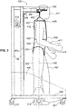
- Fig. 1 shows a schematic front view of an apparatus 100 for gait training according to an embodiment of the invention with a person 410 attached to the apparatus 100.
- the apparatus 100 has a frame comprising a left column 101 and a right column 102 (left and right in relation to the person using the apparatus) connected together in the upper part of the frame through two crossbeams 600 connecting the two columns 101 and 102 in a predetermined distance one from the other creating the space for accommodating the person 410.
- the crossbeam 600 arrangement can be adjusted in its width through telescoping connections 601 and 602 provided in the upper and lower crossbeams 600.
- the outer elements of the telescoping connections are arranged in the center beam part.
- the length of the crossbeam arrangement 600 between the telescoping point 601 and 602 is adjustable so that the shoulders 412 of a person positioned in the apparatus are positioned below the side arms 301 and 302 as will be explained below.
- the head 411 of the person 410 can be positioned just in front of the crossbeams 600 so that the head 411 may extend beyond the upper part of the apparatus 100 as shown in Fig. 1 .
- Fig. 2 shows a schematic side view of the apparatus of Fig. 1 with the elements used to provide the left base 201 and the right base 202 of the apparatus 100.
- Each base 201 and 202 comprises a horizontally arranged beam.
- a front support wheel 221 and a back support wheel 222 At the free ends of the beam are attached a front support wheel 221 and a back support wheel 222. They can be oriented in the direction of the beam or they can be attached to as turn when the base is pivoted.
- the two parallel arranged elements provide a stable apparatus 100.
- Two drive units 210 are attached to the left base 201 and right base 202, respectively driving a left driven wheel 211 and a right driven wheel 212 provided on the same horizontal axis 215.
- the horizontal axis 215 of the driven wheels 211 and 212 is preferably located in the frontal plane 420 of the person 410 attached in the harness 500 of apparatus 100.
- the center of gravity of the person 410 is essentially in or near the plane mainly crossing axis 215.
- the columns 101 and 102 are provided behind said frontal plane 420 seen on Fig. 2 , i.e. behind the driven wheels 211 and 212 so that they are not in the field of vision of the person 410.
- the weight support system 400 or weight relief mechanism is preferably provided in the vicinity of the base elements 201 and 202 to achieve a stable configuration with a low center of gravity.
- the crossbeam 600 further comprises an arm arrangement 300 with a left side arm 301 and a right side arm 302 extending in parallel to the left base 201 and right base 202, respectively. In other words, they are oriented essentially perpendicular to the crossbeams 600.
- the arm arrangement 300 is attached to the upper of the two crossbeam arrangements 600. Of course, it would also be possible to only provide one crossbeam arrangement.
- Pulleys 311 and 312 are attached to guiding rails 351 and 352 which are provided below arms 301 and 302.
- the guiding rails can be inter alia gliding rails.
- the axes of pulley 311 and 312 are oriented in parallel and below the direction of movement provided by the guiding rails 351 and 352.
- Pulleys 311 and 312 are positioned above the shoulders 412 of a person 410 using the apparatus.
- the horizontal distance between the arms 301 and 302 and therefore the horizontal distance between the pulleys 311 and 312 is such that the head 411 of the person 410 can be positioned between the arms 301, 302 in a way being comfortable for said person 410.
- the guiding rails 351 and 352 are adapted to glide forward and backward upon any force exerted in this direction upon either pulley 311 or 312.
- These pulleys 311 and 312 are wheels mounted to turn around said horizontal axis connected to the guiding rails 351 and 352 wherein the axis is oriented in parallel to the side arms 301 or 302 respectively. Therefore, a left rope 401 and right rope 402 (left and right in relation to the person) can be redirected by set pulleys 311 and 312 from a horizontal portion of the rope in parallel to the crossbeams 600 into an essentially downward direction to be attached at points 501 and 502 to the harness 500.
- the ropes 401 and 402 are slightly inclined one to the other in the frontal plane of the person 410 which is due to the fact that the attachment points 501 and 502 are at the pelvis part 520 of the harness 500. Additionally they are provided in front and in the back of the person 410. In other words, ropes 401 and 402 are separated into two rope parts 426 and 427 to be attached in front and in the back of the harness 500. For that the rope parts 426 and 427 are maintained in a distance by rod 428.
- the harness 500 as pelvis part comprises crotch straps 521 connecting the front part of the harness 500 to the back part.
- the guiding rails 351 and 352 can use gliding or sliding rails or linear bearings.
- the guiding rails 351 and 352 can be curved in order to modify the amount of force required to act on the pulleys 311 and 312 for moving the pulleys 311 and 312 on the guiding rails 351 and 352. This can be achieved preferably that the guiding rails are provided in the plane of the beams 301 and 302 curved according to a circular track wherein the center of the track is the nearest pulley 315.
- the guiding rails 351 and 352 in the plane of the beams 301 and 302 curved according to a circular track wherein the center of the track is the pulley 315 opposite to the guiding rail, in other words, the free ends of the guiding rails 351 and 352 are nearer one to the other than the middle portions. Then the rope on the opposite side remains at the same length when turning, whereas the rope on the turning side needs a prolongation.
- Rope 401 and rope 402 are redirected by pulley 311, 312 into a horizontal direction towards the left column 101 and the right column 102 to be redirected with a combination of further pulleys 315 and 316 into a rope part oriented in parallel to the columns 101 and 102 and ending in and attached to a weight support system 400.
- Such a weight support system 400 or weight relief system can be of any kind known in the art as e.g. the electronic system disclosed by the applicant in EP 1 586 291 A1 or the mechanical compensation scheme as developed by the applicant in EP 1 908 442 A1 or it can also be a simple spring attached to the base 201 or base 202.
- the harness 500 with pelvis part 520 and e.g. four attachment points 501, 502 for rope sections 426 and 427 being combined into a left rope 401 and right rope 402 just below the pulleys 311 and 312 allows for a secure positioning of the person 410 in the apparatus with its frontal plane above the axis 215 of the driven wheels.
- FIG. 2 shows a schematic side view of the apparatus of Fig 1 with the frontal plane 420 as a dashed line connecting the attachment portion of pulleys 311 and 312 in a vertical orientation to the ground crossing the axis 215 of the driving wheels 211 and 212.
- the front part 426 of the rope 402 as well as the back part 427 of the rope 402 are attached at the front and back attachment points 502 at the pelvis part 520 of harness 500 wherein the distance between the rope parts 426 and 427 are maintained between the attachments point and the shoulder region 412 of the person by distance rods 428 providing the lower base of the joining triangle for the rope parts 426 and 427 to the unique right body part rope 402 as shown in Fig. 2 .
- the left part rope 401 comprises the same elements on the other side of the head 411 of the person 410.
- Sensors detecting the intended movement of the person can be inter alia sensors provided at the guiding rails 351 and 352 detecting the position of the pulley attachment of pulleys 311 and 312, respectively. If e.g. there would be no guiding rails 351 and 352 but pulleys 311 and 312 could be inclined to follow an inclination of rope portions 401 or 402 towards the bifurcation into sections 426 and 427, then sensors could detect this inclination of rope or pulleys.
- the pelvis When the person 410 is trying to make a turn, e.g. turning right, the pelvis is turning in the way that the left part of the pelvis above the left leg 421 is advancing further than the right part. This is immediately transferred to the harness 520, especially since crotch straps 521 connect the leg position to the pelvis position, and via the rope parts 426 and 427 as well as the ropes 401 and 402 to the attachment portions at the arms 300. Then, pulley 311 is gliding forward on arm 301 through the guiding rail 351 whereas pulley 312 is moving backward on its guiding rail 352, or forward by a smaller amplitude.
- This movement is detected by the sensors and translated into drive signals for drive unit 210 so that driven wheel 211 is moving faster whereas driving wheel 212 is moving slower or even stopping or even moving backward enabling a turning of the whole apparatus 100, optionally while the person 410 is advancing at the same time.
- Fig. 3 shows a schematic perspective view of main elements of an apparatus for gait training according to a further embodiment of the invention with a leg orthosis 700 as part of the apparatus.
- the ropes 401 and 402 are shown but the person to be attached within an harness is omitted to better show the leg orthosis 700 attached at leg frame parts 710 attached at the columns 101 and 102.
- the leg orthosis can be described as shown in Fig. 5 of WO 00/28927 A1 of the applicant.
- the left and right orthosis 701 and 702 comprise cuffs 711 and 712 which can be displaced in the direction of axis 215.
- cuffs 711 and 712 are attached on the leg orthosis parts to support the movement of the leg 421 or 422 of a person 410 in the sagittal plane but the cuffs 711 and 712 are free to be displaced in the transverse direction.
- This can be achieved through mounting the cuffs 711 and 712 on hollow sleeves 716 which are gliding on inner rods 715 attached to the relevant portion of the leg orthosis.
- Inner rods 715 are oriented in parallel to axis 215 and perpendicular to plane 420.
- cuffs 711 and 712 may be mounted on guiding rails oriented in parallel to axis 215.
- Sensors detect the transverse movement of one or more cuffs and via control unit 900 give control signals to the drive unit 210 which then drive wheels 211 and 212 to move the apparatus 100.
- Linear potentiometers mounted on or near the sleeves 716 or guiding rails can be used in an embodiment of the invention.
- linear sensors similar to linear sensors 801 and 802 mentioned below or ultrasonic distance sensors can be used in further embodiments of the invention for detecting the lateral movement of the cuffs.
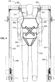
- Fig. 4 shows a schematic front view of main elements of an apparatus 100 for gait training according to another embodiment of the invention with a person 410 attached to the apparatus 100 with a different harness 500 in comparison to Fig. 1 . All similar or identical elements have received similar or identical reference numerals throughout the specification.
- the frame or apparatus 100 of Fig. 1 is identical to the frame of Fig. 1 .
- Harness 500 is here a two part harness with a torso part or upper part 510 and a lower part or pelvis part 520, the latter having the crotch straps 521.
- the upper part 510 and the pelvis part 520 are connected with stretch sensors 531 and 532. These are or can be provided in the front and the back part of the harness 500.
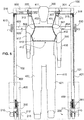
- Fig. 5 shows a schematic front view of main elements of an apparatus 100 for gait training according to another embodiment of the invention with a person 410 attached to the apparatus with a different harness 500 in comparison to Fig. 1 .
- a torso part 510 is provided so that the detection of movement of the user is to be detected by the orientation and position of the ropes 401, 402.
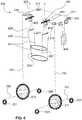
- Fig. 6 shows a schematic diagram of an apparatus 100 for gait training depicting an arrangement of the frame and ropes in connection with one combined weight relief mechanism 400 according to an embodiment of the invention.
- Rope 401 is redirected over pulley 311 which is attached at rail 351.
- a linear sensor 801 detects the position of pulley 311 attachment on rail 351. It can also be an angular sensor relating to pulley 311.
- Linear sensor 802 is provided on the other side detecting the position of the rope in relation to the right pelvis portion of the person in the pelvis harness 520.
- Fig. 7 shows a schematic diagram of an apparatus 100 for gait training depicting an arrangement of the frame and ropes in connection with a weight relief mechanism 400 according to the embodiment according to Fig. 1 .
- Fig. 8 shows a schematic diagram of an apparatus 100 for gait training depicting an arrangement of the frame and ropes in connection with a weight relief mechanism 400 according to a further embodiment of the invention.
- the ropes 401 and 402 are replaced by a single rope 403 attached to a transverse rod 429 then providing the attachment rope section 426, 427 for the pelvis harness 520.
- spring loaded angular sensors 811 and 812 are connected with wires 810 and are detecting the pelvis position.
- the single rope 403 attached at a central guiding rail 353 is redirected towards the weight life mechanism 400.
- the advantage of the possibility to have the head 411 of the person 410 determining the height of the apparatus 400 is lost within this embodiment.
- Fig. 9 shows a schematic diagram of an apparatus 100 for gait training depicting an arrangement of the frame and ropes in connection with a weight relief mechanism 400 according to a further embodiment of the invention.
- the frame parts are shown with one single crossbeam 600 and two parallel side arms 301 and 302, wherein the rope 402 is redirected via the crossbeam 600 as in Fig. 6 to the single weight relief mechanism 400.
- Fig. 10 shows a schematic diagram of an apparatus 100 for gait training depicting an arrangement of the frame and ropes 401 and 402 in connection with telescoping mechanisms for adjustment according to another embodiment of the invention.
- Telescoping adjustments 601 and 602 are provided to allow approaching the bases 201 and 202 one towards the other while providing one single relief mechanism 400.
- Further vertical telescoping adjustments 611 and 612 are provided to allow an adjustment of the height of the apparatus 100. Said adjustment cannot only be provided to allow an adaptation of the apparatus to shorter or taller persons 401, but it can also be used in the context of a patient lift. Then the bases 201 and 201 are separated as far as possible to position the apparatus behind a bed or wheelchair.
- the adjustments 611 and 612 reduce the height to attach the harness 520 to the user. Then the adjustments 611 and 612 are lengthened to lift the person 520 from a sitting or lying position into a standing position. The wheelchair or bed is pushed away and the basis 201 and 202 are positioned closer one to the other to provide a stable apparatus 100 and the apparatus 100 is then adapted to pass through narrow doorways.
- Fig. 11 shows a schematic diagram of an apparatus 100 for gait training depicting an arrangement of the frame and ropes in connection with an integrated orthosis 700 according to another embodiment of the invention.
- cuffs 711 and 712 can freely move in the direction of the double arrow 720 in parallel to axis 215 while the orthosis 700 provide a guiding of the person's legs 421 and 422 in the movement direction.
- orthosis 700 is mounted essentially in the frontal plane 420, which comprises the two vertical lines 419 as shown in Fig. 19 .
- the legs of a user are essentially positioned between the driven wheels 211 and 212 in the frontal plane 420.
- any turning movement of the user is supported by the adjustable cuffs 711 and 712 and followed by subsequent movement of the wheels 211 and 212 to adapt the position of the frontal plane 420 in the new direction.
- Fig. 12 shows a schematic view of the detection scheme of a user movement.
- the frontal plane 420 is the dashed line seen, before a movement of a person 410.
- the person 410 advances and turns right. Therefore the frontal pelvis plane 423 of the person in inclined to the right and is in front of the previous frontal plane, so that the back gliding of pulley 312 by an amount of m2 is smaller than the forward movement of pulley 311 by an amount of m1.
- the amount of the movements m1 and m2 depend on the width w of the person.
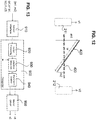
- Fig. 13 shows a diagram of the control unit 900 of an apparatus according to the invention.
- the sensor interface 910 is connected with the different sensors as mentioned above. This can include the position sensors of the rails or angular sensors for the pulley orientation or the length of the stretch sensors.
- the sensor input 910 is processed within the control unit in a sensor processing stage 920 and handed over to the intention detection 930, where input relating to the person 410 as the body width w is used to provide a control signal to generate in the movement control section 940 a drive signal to the motor drive unit 950 which drives the elements 210 and generate a speed v1 and v2 for the different driven wheels 211 and 212 which then rotates the apparatus 100 according to the intention of the person 410 in the harness 500.
- Fig. 14 shows a schematic diagram of an apparatus 100 for gait training depicting an arrangement of the frame and ropes in connection with a weight relief mechanism 400 according to a further embodiment of the invention.
- the frame parts are shown with one single crossbeam 600 and two transverse side arms 321 and 322, wherein rope 402 is redirected via the crossbeam 600 as in Fig. 6 to the single weight relief mechanism 400.
- Pulleys 311 and 312 can in one embodiment being attached at the side arms 321 and 322 which can be pivoted freely and independently relative to the arrangement 300 according to the double arrows 320, such that when the person 410 moves, the transverse side arms 321 and 322 rotate independently around this horizontal axis due to the force acting on the ropes 401 and 402, wherein such rotations are measurable, e.g. by angular sensors like potentiometers, and providing input to the control unit 900.
- the pulleys 311 and 312 for directing the ropes towards the user can be rotatably attached at the free ends of the transverse side arms 321 and 322 and then the pulleys 311 and 312 rotate according to the double arrows 320.
- Fig. 15 shows a schematic diagram of an apparatus for gait training depicting another arrangement of the frame and ropes in connection with a weight relief mechanism according to another embodiment of the invention, in which the telescoping mechanism is used similar to the embodiment of Fig. 10 to lift the person and adapt to the height of the person.
- the telescoping connections 611 and 612 are preferably integrated in the columns 101 and 102 and allow for a height adjustment of the harness attachment portion.
- This apparatus according to Fig, 15 now allows the separation of the adjustment of the length of the ropes from the dynamic weight relief which was usually combined in the apparatus as mentioned in the prior art.
- the side arms 331 and 332 are attached at weight relief columns 451 and 452, respectively, which are in turn fixedly provided on the crossbeam 600.
- the weight relief columns 451 and 452 can comprise a spring actioned device working according to double arrow 450 allowing an independent and essentially vertical movement of the side arms 331 and 332, preferably in a range of up to 15 centimetres, because such an extent is the maximum usual difference of the height of a torso above ground while walking through an entire step.
- This e.g. simple spring attachment of the side arms 331 and 332 then relates to the dynamic weight relief.
- the ropes 401 and 402 of a predefined, optionally mechanically adjustable, length are attached at the guiding rails 351 and 352 which are in turn attached at the side arms 331 and 332, respectively.
- crossbeam 600 is sectioned as already explained in connection with Fig. 10 allowing for a width adjustment of the device, i.e. defining the transverse distance of base column 201 and 202 and thus the available free space between wheels 211 and 212 for walking.
- the columns 451 and 452 are fixed rods and the side arms 331 and 332 are pivotably connected to them to rotate around a horizontal axis parallel to crossbeam 600. Then the length adjustment of the ropes 401 and 402, allowing for an up- and-down movement of the guiding rails and attachment points of the rope 401 and 402 depends on the inclination of the side arms 3 3 1 and 332.
- the columns 451 and 452 are fixed rods and the side arms 331 and 332 are pivotably connected to them to rotate around a vertical axis parallel to each column 451 and 452, respectively. Then the rotation of the side arms 331 and 332 can be detected by an angular sensor and indicate a turning movement of the attached user in harness 500. Here, they pivot in the horizontal plane on both sides of the head of the person in the apparatus.
- spring actuated columns 451 and 452 or pivotable side arms 331 and 332 as mentioned before, both solutions being related to a dynamic weight relief.
- the adjustment of the rope length is provided by the telescoping arrangement of the vertical columns 101 and 102.
- This can be motorized, using a worm which is actuated by a driving wheel or other mechanisms to raise or lower the upper crossbeam arrangement over ground.
- the weight support system incorporated in columns 451 and 452 or through pivotable arms 331 and 332 allows for a vertical movement portion at least of the free ends of arms 331 and 332 and applies forces to these arms 331 and 332 via the weight support components in order to provide the at least partial unloading of the person.
- the weight support components may be springs in columns 451 and 452.
- the weight support components may be more elaborate mechanisms that provide essentially constant unloading over the vertical movement range of arms 331 and 332 in direction of double arrows 450, e.g. similar to the mechanical compensation scheme as developed by the applicant in EP 1 908 442 A1 . It is noted that the direct attachment of ropes 401 and 402 to the side arms is also possible in connection with the embodiments of Fig.
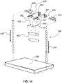
- Fig. 16 shows a schematic diagram of an apparatus for gait training depicting another arrangement of the frame and ropes in connection with a weight relief mechanism not forming part of the invention, wherein the apparatus 100 is placed over a treadmill 290.
- Fig. 16 shows a schematic diagram of the "upper" components of an apparatus 100 for gait training that is placed over a treadmill 290 as fixed basis.
- Fig. 17 shows a detail view of the beam arrangement of the embodiments of Fig. 1 to 5 .
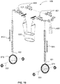
- Fig. 18 shows a schematic diagram of an apparatus for gait training depicting an arrangement of a different fixed-size frame and ropes in connection with a weight relief mechanism according to a further embodiment of the invention.
- the apparatus 100 has a frame comprising a left column 101 and a right column 102 connected together in the upper part of the frame through a crossbeam 600 connecting the two columns 101 and 102 in a predetermined distance one from the other creating the space for accommodating the person 410 to be located in between.
- the fixed frame with fixed length columns 101 and 102 attached at the movable base 200, here at the rear support wheels 222 and a fixed length crossbeam 600.
- the dimensions of the frame are preferably chosen to be able to pass through the usual door frames.
- the frame according to this embodiment is fixed and has no telescoping elements for adjustment of height or width.
- the adjustment for the patient's height and supporting lifting are done by linear drives 471 and 472 attached directly or indirectly at the columns 101 and 102, respectively, for moving the left and right weight support units 481 and 482, respectively, up and down.
- linear drives 471 and 472 attached directly or indirectly at the columns 101 and 102, respectively, for moving the left and right weight support units 481 and 482, respectively, up and down.
- the weight support units 481 and 482 can comprise a spring actioned device working according to the depicted double arrow allowing an independent and essentially vertical movement of the additional crossbeams 620, preferably in a range of up to 15 centimetres, because such an extent is the usual difference of the height of a torso above ground while walking through an entire step.
- This e.g. simple spring attachment of the additional crossbeam 620 then relates to the dynamic weight relief.
- the ropes 401 and 402 of a predefined, optionally mechanically adjustable, length are attached at the guiding rails 351 and 352 which are in turn attached at additional crossbeam 620, respectively.
- Additional crossbeam 620 is shown in two parts with the arm arrangement at the inner ends. Double arrow 350 shows the direction of the compensating motion of ropes 401 and 402 in the forward and backward direction along the arm arrangement. It is also possible that the additional crossbeam 620 is one piece extending in parallel to crossbeam 600. It is preferred that vertical oriented linear drives 471 and 472 as well as the weight support units 481 and 482 do not extend beyond the dimensions of columns 101, 102 and crossbeam 600.
- Arm arrangement 300 is directed opposite to crossbeam 600 and has a length that, when the ropes 401 and 402 are in a middle position along the arm arrangement 300, the ropes are in the same plane as the vertical line in frontal plane 419, allowing the person walking in the apparatus to be maintained essentially uprightly and in the vicinity of said plane 420.
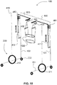
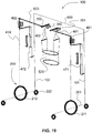
- Fig. 19 shows a schematic diagram of an apparatus for gait training depicting an arrangement of a different fixed-size frame and ropes in connection with a weight relief mechanism according to a further embodiment of the invention, similar to Fig. 18 . Similar or identical features have received similar or the same reference numerals.
- the linear drives 471 and 472 are in parallel to columns 101 and 102, especially in direction of the driven wheels 211 and 212.
- the difference between the two embodiments of Fig. 18 and Fig. 19 are related to the arrangement of the weight support units 481 and 482 which are provided in parallel to the linear drives but in line with the vertical line in the frontal plane 419, above the driven wheels 211 and 212, respectively.
- the function of the adjustable columns 451, 452 of Fig. 16 as to provide a lifting function of the user is integrated into the weight support units 481, 482 which do not change the dimensions of the external frame 600. In other words, the weight support units provide the partial weight support over a certain vertical range of positions of the arms 300.
- the adjustable columns can be attached to and vertically moved by linear drives or telescoping elements 611, 612 for adjustment to the patient's height and lifting, while the left and right column 101, 102 are fixedly connected by the crossbeam 600.
- the apparatus can apply three or more crossbeams 600 such that this apparatus comprises one crossbeam that connects the left and right column 101,102, two half crossbeams that are connected to the left column via the first telescoping connection 611 or the right column 102 via the second telescoping connection 612 respectively, the telescoping connections being configured to vertically move said half crossbeams, wherein either the left and right adjustable columns 481, 482 are attached to one of said half crossbeams 620, or the left adjustable column 481 and to which the side arm 331 which provides the guiding rail 351 is attached to the left half crossbeam and vice versa.
Landscapes
- Health & Medical Sciences (AREA)
- Life Sciences & Earth Sciences (AREA)
- General Health & Medical Sciences (AREA)
- Animal Behavior & Ethology (AREA)
- Public Health (AREA)
- Veterinary Medicine (AREA)
- Nursing (AREA)
- Physical Education & Sports Medicine (AREA)
- Epidemiology (AREA)
- Pain & Pain Management (AREA)
- Rehabilitation Therapy (AREA)
- Biophysics (AREA)
- Orthopedic Medicine & Surgery (AREA)
- Physiology (AREA)
- Dentistry (AREA)
- Oral & Maxillofacial Surgery (AREA)
- Physics & Mathematics (AREA)
- Pathology (AREA)
- Engineering & Computer Science (AREA)
- Biomedical Technology (AREA)
- Heart & Thoracic Surgery (AREA)
- Medical Informatics (AREA)
- Molecular Biology (AREA)
- Surgery (AREA)
- Rehabilitation Tools (AREA)
Claims (14)
- Appareil (100) pour l'entraînement à la marche ayant une base mobile (200) comprenant une base gauche (201) et une base droite (202), dans lequel une unité d'entraînement (210) est prévue à chacune des deux bases (201, 202) pour déplacer la base mobile (200), un agencement de bras (300) s'étendant à partir de la base mobile (200), un système de support de poids (400) pour permettre à une personne (410) d'être au moins partiellement suspendue par le haut via ledit agencement de bras (300) dans un harnais (500), un détecteur de mouvement (801, 802, 531, 532) pour détecter un mouvement de la personne (410) et une unité de commande (900) adaptée pour commander lesdites unités d'entraînement (210) en réponse à un mouvement de la personne (410) détecté par le détecteur de mouvement (801, 802, 531, 532) de telle sorte que la base mobile (200) suit la personne (410) dans une plage de distance prédéterminée et dans une plage angulaire prédéterminée par rapport à une direction de mouvement de la personne (410), caractérisé en ce que l'agencement de bras (300) comprend deux bras latéraux (301, 302) s'étendant dans un plan (420) s'étendant depuis un axe commun (215) des unités d'entraînement (210) pour présenter l'harnais (500) au voisinage dudit plan (420) au-dessous des bras latéraux (301, 302), dans lequel ledit plan (420) est essentiellement orienté debout.
- Appareil selon la revendication 1, dans lequel la personne (410) doit être suspendue avec au moins un câble (401, 402, 403) fixé au harnais (500), caractérisé en ce que le détecteur de mouvement (801, 802) comprend au moins un capteur linéaire ou angulaire détectant la position ou l'angle d'un câble relié au harnais (500) ou d'autres câbles de mesure prévus sous tension pour ladite mesure de déflexion angulaire.
- Appareil selon la revendication 1 ou 2, caractérisé en ce que les unités d'entraînement (210) sont agencées de manière centrale avec un harnais (500) dans le plan (420) des unités d'entraînement (210) et dans lequel l'unité de commande (900) est adaptée pour commander les unités d'entraînement (210) afin de modifier l'orientation angulaire de la base mobile (200) de sorte que l'angle du corps du patient par rapport audit plan (420) est nul.
- Appareil selon l'une quelconque des revendications 1 à 3, dans lequel les bras latéraux (301, 302) sont disposés à une hauteur telle que la tête (411) de la personne (410) peut être positionnée entre ces bras latéraux (301, 302).
- Appareil selon l'une quelconque des revendications 1 à 4, dans lequel deux cordes (401, 402) sont prévues et disposées entre des poulies (311, 312) au niveau des bras latéraux (301, 302) et deux points (501, 502) sur les côtés du harnais (500) au-dessus des parties d'épaule du harnais (500), les poulies (311, 312) pouvant se déplacer librement dans la direction des bras latéraux (301, 302) pour la détection d'un mouvement de rotation de la personne (410).
- Appareil selon l'une quelconque des revendications 1 à 4, dans lequel deux cordes (401, 402) sont prévues et disposées entre des poulies (311, 312) sur les bras latéraux (301, 302) et deux points (501, 502) sur les côtés du harnais (500) au-dessus des parties d'épaule du harnais (500), les bras latéraux (301, 302) pouvant soit pivoter librement autour d'un axe vertical, soit tourner librement autour d'un axe horizontal et indépendamment de l'agencement de bras (300) pour détecter un mouvement de rotation de la personne (410).
- Appareil selon l'une quelconque des revendications 1 à 4, dans lequel les câbles (401, 402) sont fixés directement ou par l'intermédiaire de rails de guidage (351, 352) déplaçables longitudinalement sur les bras latéraux (331, 332), tandis qu'au moins lesdits points de fixation des câbles (401), 402) sont montés de manière déplaçable dans la direction verticale pour une quantité prédéterminée avec un système de support de poids, qui est une fixation verticale à ressort des bras latéraux (331, 332) avec la traverse (600) ou la fixation pivotante des bras latéraux (331, 332) autour d'un axe horizontal transversal.
- Appareil selon l'une quelconque des revendications 1 à 7, dans lequel les câbles (401, 402) sont fixées au harnais (500) au niveau d'une partie de harnais de bassin (520), en particulier dans lequel des sangles d'entrejambe (521) sont prévues pour une transmission directe d'un mouvement de rotation de la personne (410) sur les câbles (401, 402).
- Appareil selon l'une quelconque des revendications 1 à 8, dans lequel chaque câble (401, 402) est séparé dans une section de câble avant et dans une section de câble arrière (426, 427) séparées par une tige de distance (428) au-dessus de l'épaule (412) d'une personne (410), dans lequel les sections de câble avant et arrière (426, 427) sont attachées (501, 502) au harnais (500) à l'avant et à l'arrière de l'utilisateur (410).
- Appareil selon l'une quelconque des revendications 1 à 9, dans lequel l'harnais (500) comprend une partie supérieure (510) et une partie inférieure (520), dans lequel la partie supérieure (510) est reliée à la partie inférieure (520) avec au moins un capteur d'étirement (531, 532) pour une mesure de l'orientation du bassin de la personne (410) par rapport à l'orientation de l'épaule de la personne (410).
- Appareil selon l'une quelconque des revendications 1 à 10, dans lequel la liaison entre la base mobile (200) et l'agencement de bras (300) peut être étendue verticalement (611, 612), en particulier par un arrangement télescopique.
- Appareil selon l'une quelconque des revendications 1 à 11, dans lequel une première connexion télescopique (601) est prévue entre la base mobile à gauche (201) et le bras du côté gauche (301) et dans lequel une deuxième connexion télescopique (602) est prévue entre la base mobile à droite (202) et droit (302) pour disposer la base mobile gauche (201) ainsi que la base mobile légère (202) à une distance prédéterminée l'une de l'autre.
- Appareil selon l'une quelconque des revendications 1 à 12, dans lequel une orthèse de jambe gauche (701) et une orthèse de jambe droite (702) sont prévues et fixées au cadre (710) de l'appareil (100), dans lequel les orthèses (701, 702) comprennent des manchettes (711, 712) qui peuvent être déplacés dans la direction du plan (420).
- Appareil selon la revendication 13, dans lequel les manchettes (711, 712) sont montées sur un élément télescopique (715, 716) relié à la partie d'orthèse entraînée (701, 702).
Applications Claiming Priority (2)
| Application Number | Priority Date | Filing Date | Title |
|---|---|---|---|
| EP14176412 | 2014-07-09 | ||
| PCT/EP2015/065440 WO2016005367A1 (fr) | 2014-07-09 | 2015-07-07 | Appareil pour l'entraînement à la marche |
Publications (2)
| Publication Number | Publication Date |
|---|---|
| EP3166558A1 EP3166558A1 (fr) | 2017-05-17 |
| EP3166558B1 true EP3166558B1 (fr) | 2018-08-29 |
Family
ID=51167717
Family Applications (1)
| Application Number | Title | Priority Date | Filing Date |
|---|---|---|---|
| EP15734387.2A Active EP3166558B1 (fr) | 2014-07-09 | 2015-07-07 | Appareil pour l'entraînement à la marche |
Country Status (7)
| Country | Link |
|---|---|
| US (1) | US10500122B2 (fr) |
| EP (1) | EP3166558B1 (fr) |
| KR (1) | KR102335610B1 (fr) |
| CN (1) | CN106535852B (fr) |
| ES (1) | ES2699360T3 (fr) |
| RU (1) | RU2687774C2 (fr) |
| WO (1) | WO2016005367A1 (fr) |
Families Citing this family (71)
| Publication number | Priority date | Publication date | Assignee | Title |
|---|---|---|---|---|
| EP2661307A4 (fr) | 2011-01-03 | 2014-08-06 | Univ California | Stimulation épidurale à haute densité pour faciliter la locomotion, la posture, le mouvement volontaire et le rétablissement de la fonction d'autonomie, sexuelle, vasomotrice et cognitive après lésion neurologique |
| JP2014533183A (ja) | 2011-11-11 | 2014-12-11 | ニューロイネイブリング テクノロジーズ インコーポレイテッド | 運動神経、感覚、自律、性的、血管運動および認知機能の回復を可能にするための非侵襲性神経調節装置 |
| US11673022B2 (en) * | 2012-08-31 | 2023-06-13 | Blue Goji Llc. | Apparatus for natural torso and limbs tracking and feedback for electronic interaction |
| US20210001170A1 (en) * | 2012-08-31 | 2021-01-07 | Blue Goji Llc | Apparatus for natural torso and limbs tracking and feedback for electronic interaction |
| KR101584341B1 (ko) * | 2014-07-07 | 2016-01-13 | 주식회사 피앤에스미캐닉스 | 보행보조로봇 하중 보상시스템 및 이를 구비하는 보행훈련장치 |
| US10413471B2 (en) * | 2015-04-02 | 2019-09-17 | Dan Marom | Walker device |
| GB2538712B (en) * | 2015-05-25 | 2018-09-12 | Bosnak Matevz | A walking assist system comprising a user intention assesment based control system |
| EP3222332A1 (fr) | 2016-03-24 | 2017-09-27 | Hocoma AG | Dispositif de suspension pour un équilibrage de poids |
| ITUA20162627A1 (it) * | 2016-04-15 | 2017-10-15 | Mech Srl | Sistema a cavi per assistenza motoria |
| DE102016213964A1 (de) * | 2016-07-28 | 2018-02-01 | Kuka Roboter Gmbh | Hippotherapievorrichtung |
| EP3500336A2 (fr) * | 2016-08-17 | 2019-06-26 | Ecole Polytechnique Federale de Lausanne (EPFL) | Appareil comprenant un système de support pour un utilisateur et son fonctionnement en mode assistance à gravité |
| JP6742196B2 (ja) * | 2016-08-24 | 2020-08-19 | Cyberdyne株式会社 | 生体活動検出装置および生体活動検出システム |
| EP3509558B1 (fr) * | 2016-09-08 | 2022-10-26 | Trexo Robotics Inc. | Dispositif d'orthèse motorisé mobile à support de poids |
| KR101939301B1 (ko) * | 2017-01-19 | 2019-01-16 | 한국생산기술연구원 | 반중력 무한이동 가상체험장치 |
| US10272284B2 (en) * | 2017-02-01 | 2019-04-30 | Mobility Research, Inc. | Gait training apparatus for measuring supported weight on each side of a patient in real time as the patient is walking |
| GB201705748D0 (en) * | 2017-04-20 | 2017-05-24 | Greenburg Uk Ltd | A garment |
| WO2018213162A1 (fr) | 2017-05-15 | 2018-11-22 | Northwestern University | Procédé et appareil de bordage incrémental double face |
| CN107157712B (zh) * | 2017-06-20 | 2023-07-11 | 深圳市瀚翔生物医疗电子股份有限公司 | 一种下肢训练康复设备 |
| US11311447B2 (en) * | 2017-06-30 | 2022-04-26 | Northwestern University | Agility trainer |
| US20190008711A1 (en) * | 2017-07-10 | 2019-01-10 | Liko Research & Development Ab | Slingbar with Multi-Sling Compatibility |
| IT201700095769A1 (it) * | 2017-08-24 | 2019-02-24 | C O R P O 53 S R L | Dispositivo per la rieducazione della motricità nelle disfunzioni posturali |
| US20200345569A1 (en) * | 2017-08-30 | 2020-11-05 | Multi Tower Company Ivs | Two-point, four points and multiple points lifting patient lifting robots |
| GR1009681B (el) * | 2017-10-03 | 2020-01-20 | Σπυριδων Δημητριου Καλλιωρας | Τροχηλατος ορθοστατης σχηματος ''π'' ρυθμιζομενος στο υψος και στο πλατος |
| US10709633B2 (en) | 2017-11-20 | 2020-07-14 | The Regents Of The University Of California | Exoskeleton support mechanism for a medical exoskeleton |
| US12357828B2 (en) | 2017-12-05 | 2025-07-15 | Ecole Polytechnique Federale De Lausanne (Epfl) | System for planning and/or providing neuromodulation |
| CA3026301C (fr) * | 2017-12-05 | 2023-09-05 | Association De La Sclerose En Plaques De L'estrie Inc. | Systeme d'eclairage corporel destine a l'entrainement de la demarche |
| WO2019116093A1 (fr) * | 2017-12-14 | 2019-06-20 | Bionic Yantra Private Limited | Appareil et système de traitement de récipients |
| CN108272602B (zh) * | 2018-03-15 | 2023-12-19 | 合肥哈工力训智能科技有限公司 | 一种下肢康复机器人悬吊减重装置 |
| CN109044741A (zh) * | 2018-07-16 | 2018-12-21 | 郑喜勋 | 防摔倒装置 |
| CN109248049A (zh) * | 2018-07-16 | 2019-01-22 | 郑喜勋 | 防摔倒跟随结构 |
| CN109363896A (zh) * | 2018-11-05 | 2019-02-22 | 南开大学 | 一种下肢康复训练的双绳悬吊式主动减重系统 |
| CN109549805A (zh) * | 2019-01-21 | 2019-04-02 | 赣州英博机器人科技有限公司 | 一种多功能护理康复机器人及其使用方法 |
| EA037467B1 (ru) * | 2019-01-23 | 2021-03-31 | Владислав Анатольевич ЛУКАШЕВИЧ | Устройство для развития и восстановления двигательной активности человека |
| CN111631921A (zh) * | 2019-03-02 | 2020-09-08 | 杭州程天科技发展有限公司 | 一种步行跟随康复训练设备与自动跟随控制方法 |
| KR102153217B1 (ko) * | 2019-03-28 | 2020-09-07 | 찬 일 함 | 보행 재활 기구 |
| US11259982B2 (en) | 2019-04-25 | 2022-03-01 | Ryan Charles Ognibene | Treadmill attachment for anti-gravity suspension system |
| CN110210392B (zh) * | 2019-05-31 | 2022-12-09 | 吉林化工学院 | 一种基于概率论的步态识别装置 |
| DE102019118819A1 (de) * | 2019-07-11 | 2021-01-14 | Reha-Stim Medtec AG | Vorrichtung zur therapeutischen Bewegungsunterstützung eines Patienten und zur Gewichtsentlastung von unteren Extremitäten eines Patienten, und Bewegungseinrichtung |
| CN110403802B (zh) * | 2019-07-16 | 2024-05-31 | 广东智爱机器人科技有限公司 | 电动姿势矫正减重步行训练装置 |
| CN110450135B (zh) * | 2019-07-30 | 2021-01-19 | 华中科技大学鄂州工业技术研究院 | 一种动态悬吊式体重支持系统 |
| US11813216B1 (en) * | 2019-08-08 | 2023-11-14 | Richard Joshua Riess | Multi-therapeutic patient lift and parallel bars system |
| RU196291U1 (ru) * | 2019-11-05 | 2020-02-25 | Флорит Фаридович Ягафаров | Устройство для удержания человека от падения |
| CN110934715B (zh) * | 2019-11-18 | 2021-09-21 | 南京伟思医疗科技股份有限公司 | 一种实现下肢机器人与减重车协同运动的控制系统及方法 |
| EP3824948A1 (fr) | 2019-11-19 | 2021-05-26 | ONWARD Medical B.V. | Système de planification et/ou de commande pour un système de neuromodulation |
| EP3827875B1 (fr) | 2019-11-27 | 2023-07-05 | ONWARD Medical N.V. | Systeme de neuromodulation |
| PL4117597T3 (pl) | 2019-12-23 | 2025-03-17 | Hocoma Ag | Aparat do aktywacji nóg i aparat do rehabilitacji chodu |
| US11071677B1 (en) * | 2020-01-28 | 2021-07-27 | Richard S. Burns | Bodyweight unloading locomotive device |
| US11617704B2 (en) * | 2020-01-28 | 2023-04-04 | Richard S. Burns | Bodyweight unloading locomotive device |
| WO2021178783A1 (fr) * | 2020-03-06 | 2021-09-10 | Dilorenzo Robert L | Systèmes d'assistance à la déambulation |
| CN111449916B (zh) * | 2020-05-06 | 2024-08-09 | 广州一康医疗设备实业有限公司 | 下肢康复训练设备用减重模组 |
| CN111991755B (zh) * | 2020-08-24 | 2021-09-10 | 武汉沃森拓客科技有限公司 | 一种在线变刚度的智能反重力动态悬吊系统 |
| CN112079258A (zh) * | 2020-09-08 | 2020-12-15 | 中原动力智能机器人有限公司 | 可移动微重力环境模拟装置 |
| KR102238707B1 (ko) | 2020-10-28 | 2021-04-12 | 알바이오텍 주식회사 | Ar 발자국 가이드 기반 보행훈련 시스템 |
| CN112603752B (zh) * | 2020-11-30 | 2023-07-18 | 浙江理工大学 | 一种绳拉式柔性下肢外骨骼助力机器人及其运动控制方法 |
| CN112754862A (zh) * | 2021-01-08 | 2021-05-07 | 浙江工业大学 | 柔性升降式自主康复训练仪 |
| CN112972215B (zh) * | 2021-04-01 | 2023-09-29 | 南京伟思医疗科技股份有限公司 | 一种下肢步行康复训练车及其转向控制办法 |
| CN115192966A (zh) * | 2021-04-08 | 2022-10-18 | 华瑞福恒(广州)科技有限公司 | 一种全方位密集训练数字采集装置 |
| US12502325B2 (en) | 2021-09-30 | 2025-12-23 | Redline Innovations, Inc. | Lifting device and associated methods |
| WO2023056309A1 (fr) * | 2021-09-30 | 2023-04-06 | Redline Innovations, Inc | Dispositif de levage et méthodes associées |
| KR102819126B1 (ko) * | 2021-12-17 | 2025-06-13 | 성균관대학교산학협력단 | 체중탈부하 지면보행 훈련 장치 및 방법 |
| CN114733143A (zh) * | 2022-04-12 | 2022-07-12 | 谢君 | 减重运动康复训练器械 |
| CN114870346A (zh) * | 2022-05-30 | 2022-08-09 | 南开大学 | 一种面向步行功能康复训练的主动跟随式减重机器人 |
| US20240058199A1 (en) * | 2022-08-18 | 2024-02-22 | The Trustees Of Columbia University In The City Of New York | Mobile Tethered Pelvic Assist Device for Generating Timed Frontal Plane Pelvic Moments During Overground Walking |
| CN115429637A (zh) * | 2022-09-16 | 2022-12-06 | 力迈德医疗(广州)有限公司 | 一种下肢康复训练机器人 |
| IT202200019959A1 (it) * | 2022-09-28 | 2024-03-28 | Guido Belforte | Sistema di sospensione e di sgravio del peso per il cammino a terra e per esercizi di riabilitazione delle gambe |
| US20240130919A1 (en) * | 2022-10-13 | 2024-04-25 | Board Of Regents, The University Of Texas System | System for gait training |
| KR102821387B1 (ko) * | 2022-12-01 | 2025-06-16 | 경북대학교 산학협력단 | 이동 대상의 낙상 방지와 위치 추종을 위한 크레인 시스템 및 그에 따른 제어방법 |
| EP4648930A1 (fr) * | 2023-01-09 | 2025-11-19 | Sarcos Corp. | Exosquelette de marche |
| CN117815044A (zh) * | 2024-01-19 | 2024-04-05 | 南洋理工大学 | 移动式动态重量支撑装置 |
| US12467521B1 (en) | 2024-05-10 | 2025-11-11 | Yarro Studios, Inc. | 3D-printed telescoping actuator |
| US12582865B2 (en) | 2024-05-10 | 2026-03-24 | Andrew B Thomas | Suspension sling abdominal exercise device |
Family Cites Families (31)
| Publication number | Priority date | Publication date | Assignee | Title |
|---|---|---|---|---|
| US953962A (en) * | 1909-09-03 | 1910-04-05 | Charles W Lane | Device for raising and moving invalids. |
| DK135287D0 (da) | 1986-04-08 | 1987-03-17 | Viggo Guldmann | Mobilkran til haandtering af patienter |
| SU1477408A1 (ru) * | 1986-12-10 | 1989-05-07 | Ю.М.Самойлов, А.Д.Джураев и О.Д.Слобод нюк | Устройство дл обучени ходьбе |
| SU1734741A1 (ru) * | 1989-05-18 | 1992-05-23 | А.Г. Цициков и В.И. Дикуль | Устройство дл тренировки ходьбы |
| US5174590A (en) * | 1991-07-03 | 1992-12-29 | The United States Of America As Represented By The Administrator Of The National Aeronautics & Space Administration | Compliant walker |
| US5569129A (en) * | 1994-06-10 | 1996-10-29 | Mobility Research L.L.C. | Device for patient gait training |
| US6092247A (en) * | 1998-10-02 | 2000-07-25 | Wilson; Harold R. | Powered patient lift vehicle |
| US6821233B1 (en) | 1998-11-13 | 2004-11-23 | Hocoma Ag | Device and method for automating treadmill therapy |
| US7331906B2 (en) * | 2003-10-22 | 2008-02-19 | Arizona Board Of Regents | Apparatus and method for repetitive motion therapy |
| KR100555990B1 (ko) * | 2003-10-30 | 2006-03-03 | 한국과학기술원 | 공압 분산 제어형 보행 보조 로봇 |
| EP1586291B1 (fr) | 2004-04-16 | 2008-04-09 | Hocoma AG | Appareil pour régler la hauteur et la force de soulagement agissant sur un poids |
| FR2870747B1 (fr) * | 2004-05-26 | 2009-11-20 | Thierry Albert | Dispositif d'amelioration de la motricite notamment de la marche |
| US7544172B2 (en) * | 2004-06-29 | 2009-06-09 | Rehabilitation Institute Of Chicago Enterprises | Walking and balance exercise device |
| RU46430U1 (ru) * | 2004-12-23 | 2005-07-10 | Шамарин Тимофей Григорьевич | Тренажер для больных с детским церебральным параличом |
| EA008583B1 (ru) * | 2005-05-13 | 2007-06-29 | Михаил Григорьевич Киселев | Тренажер специализированный для восстановления двигательных функций |
| EP1908442A1 (fr) | 2006-10-05 | 2008-04-09 | Hocoma AG | Dispositif pour régler la précontrainte dans un lien élastique autour d'une valeur de tension prédéterminée ou une position prédéterminée |
| US7938756B2 (en) * | 2007-02-10 | 2011-05-10 | Roy Rodetsky | Powered mobile lifting, gait training and omnidirectional rolling apparatus and method |
| US7827630B2 (en) * | 2008-01-25 | 2010-11-09 | Roger Bostelman | Home lift position and rehabilitation (HLPR) apparatus |
| JP2009195636A (ja) | 2008-02-25 | 2009-09-03 | Tokai Univ | 歩行訓練用転倒防止装置、及び歩行支援装置 |
| WO2009125397A2 (fr) | 2008-04-08 | 2009-10-15 | Motorika Limited | Dispositif et procédé pour une analyse et une rééducation de pied tombant |
| DE102008029564B4 (de) * | 2008-06-21 | 2015-12-24 | medica - Medizintechnik GmbH | Mobile Trainings-Vorrichtung zum Aufbau der Muskulatur des Gehapparates |
| CN101589984B (zh) * | 2009-07-03 | 2011-05-11 | 北京理工大学 | 一种康复机器人 |
| CN201676135U (zh) * | 2009-09-14 | 2010-12-22 | 张建卿 | 多功能残疾人康复训练助行器 |
| FR2971419B1 (fr) | 2011-02-10 | 2014-05-09 | Rise Ba | Dispositif de reeducation ambulatoire autonome |
| KR101275030B1 (ko) * | 2011-10-11 | 2013-06-17 | 주식회사 사이보그-랩 | 분리형 트레드밀을 구비한 하지 재활 훈련 시스템 |
| US20140100491A1 (en) * | 2012-10-05 | 2014-04-10 | Jianjuen Hu | Lower Extremity Robotic Rehabilitation System |
| US9844704B2 (en) * | 2012-11-09 | 2017-12-19 | Wilson Sporting Goods Co. | Basketball sensing apparatus |
| PL2730266T3 (pl) | 2012-11-09 | 2017-02-28 | Hocoma Ag | Urządzenie do treningu chodu |
| EP2922517B1 (fr) * | 2012-11-21 | 2018-10-10 | Univerzitetni Rehabilitacijski Institut Republike Slovenije SOCA | Appareil d'entraînement de man uvres d'équilibre et de rotation dynamiques pendant la marche |
| US8967642B2 (en) * | 2013-03-15 | 2015-03-03 | Entropy Enterprises, LLC | Walker |
| CN103637864B (zh) * | 2013-12-25 | 2015-03-25 | 国家康复辅具研究中心 | 脑瘫综合康复训练辅具 |
-
2015
- 2015-07-07 ES ES15734387T patent/ES2699360T3/es active Active
- 2015-07-07 WO PCT/EP2015/065440 patent/WO2016005367A1/fr not_active Ceased
- 2015-07-07 RU RU2017102220A patent/RU2687774C2/ru active
- 2015-07-07 US US15/324,476 patent/US10500122B2/en active Active
- 2015-07-07 CN CN201580037568.3A patent/CN106535852B/zh active Active
- 2015-07-07 KR KR1020177003012A patent/KR102335610B1/ko active Active
- 2015-07-07 EP EP15734387.2A patent/EP3166558B1/fr active Active
Also Published As
| Publication number | Publication date |
|---|---|
| EP3166558A1 (fr) | 2017-05-17 |
| KR20170031159A (ko) | 2017-03-20 |
| US20170165145A1 (en) | 2017-06-15 |
| US10500122B2 (en) | 2019-12-10 |
| RU2687774C2 (ru) | 2019-05-16 |
| ES2699360T3 (es) | 2019-02-08 |
| KR102335610B1 (ko) | 2021-12-06 |
| CN106535852A (zh) | 2017-03-22 |
| WO2016005367A1 (fr) | 2016-01-14 |
| CN106535852B (zh) | 2018-12-21 |
Similar Documents
| Publication | Publication Date | Title |
|---|---|---|
| EP3166558B1 (fr) | Appareil pour l'entraînement à la marche | |
| CN105392461B (zh) | 用于自动行走训练的设备 | |
| US10130547B2 (en) | Exoskeleton device with sitting support and method of operation thereof | |
| CN101835444B (zh) | 可站立式轮椅 | |
| US10413470B2 (en) | Lower limb rehabilitation training robot | |
| KR20070036783A (ko) | 보행 및 균형 운동 장치 | |
| US7731674B2 (en) | Walking assistance device | |
| KR101433284B1 (ko) | 자세조절부를 포함하는 자세균형 훈련용 보행보조기 | |
| KR102098959B1 (ko) | 착석형 지지유닛 및 이를 이용한 착석형 보행 훈련 장치 | |
| EP4344692B1 (fr) | Système de suspension et de soulagement du poids pour marcher sur le sol et pour des exercices de rééducation des jambes | |
| CN110368266A (zh) | 二自由度悬吊式姿势矫正减重步行训练器 | |
| KR20140068514A (ko) | 자세균형 훈련용 보행보조기 | |
| CN210991600U (zh) | 二自由度悬吊式姿势矫正减重步行训练器 | |
| CN113274697B (zh) | 智能踏步训练设备 | |
| KR102191984B1 (ko) | 자중을 이용한 허리 견인장치 | |
| CN114886734A (zh) | 基于外骨骼助力跟随运动的下肢康复训练机器人 | |
| CN105640734A (zh) | 可调节性平衡站立床 | |
| KR101126410B1 (ko) | 보행 보조 시스템 | |
| SE427895B (sv) | Uppresningsstol for rorelsehemmade personer | |
| KR101407465B1 (ko) | 자세균형 및 보행훈련 장치 | |
| CN117338566A (zh) | 一种卧式踏步康复训练装置 | |
| PL232365B1 (pl) | Urządzenie do rehabilitacji, zwłaszcza kręgosłupa |
Legal Events
| Date | Code | Title | Description |
|---|---|---|---|
| STAA | Information on the status of an ep patent application or granted ep patent |
Free format text: STATUS: THE INTERNATIONAL PUBLICATION HAS BEEN MADE |
|
| PUAI | Public reference made under article 153(3) epc to a published international application that has entered the european phase |
Free format text: ORIGINAL CODE: 0009012 |
|
| STAA | Information on the status of an ep patent application or granted ep patent |
Free format text: STATUS: REQUEST FOR EXAMINATION WAS MADE |
|
| 17P | Request for examination filed |
Effective date: 20170110 |
|
| AK | Designated contracting states |
Kind code of ref document: A1 Designated state(s): AL AT BE BG CH CY CZ DE DK EE ES FI FR GB GR HR HU IE IS IT LI LT LU LV MC MK MT NL NO PL PT RO RS SE SI SK SM TR |
|
| AX | Request for extension of the european patent |
Extension state: BA ME |
|
| DAV | Request for validation of the european patent (deleted) | ||
| DAX | Request for extension of the european patent (deleted) | ||
| GRAP | Despatch of communication of intention to grant a patent |
Free format text: ORIGINAL CODE: EPIDOSNIGR1 |
|
| STAA | Information on the status of an ep patent application or granted ep patent |
Free format text: STATUS: GRANT OF PATENT IS INTENDED |
|
| RIC1 | Information provided on ipc code assigned before grant |
Ipc: A61H 3/04 20060101ALI20180301BHEP Ipc: A61H 1/02 20060101ALI20180301BHEP Ipc: A61H 3/00 20060101AFI20180301BHEP |
|
| INTG | Intention to grant announced |
Effective date: 20180327 |
|
| GRAS | Grant fee paid |
Free format text: ORIGINAL CODE: EPIDOSNIGR3 |
|
| GRAA | (expected) grant |
Free format text: ORIGINAL CODE: 0009210 |
|
| STAA | Information on the status of an ep patent application or granted ep patent |
Free format text: STATUS: THE PATENT HAS BEEN GRANTED |
|
| AK | Designated contracting states |
Kind code of ref document: B1 Designated state(s): AL AT BE BG CH CY CZ DE DK EE ES FI FR GB GR HR HU IE IS IT LI LT LU LV MC MK MT NL NO PL PT RO RS SE SI SK SM TR |
|
| REG | Reference to a national code |
Ref country code: GB Ref legal event code: FG4D |
|
| REG | Reference to a national code |
Ref country code: CH Ref legal event code: EP |
|
| REG | Reference to a national code |
Ref country code: AT Ref legal event code: REF Ref document number: 1034284 Country of ref document: AT Kind code of ref document: T Effective date: 20180915 |
|
| REG | Reference to a national code |
Ref country code: IE Ref legal event code: FG4D |
|
| REG | Reference to a national code |
Ref country code: DE Ref legal event code: R096 Ref document number: 602015015618 Country of ref document: DE |
|
| REG | Reference to a national code |
Ref country code: CH Ref legal event code: NV Representative=s name: ISLER AND PEDRAZZINI AG, CH |
|
| REG | Reference to a national code |
Ref country code: NL Ref legal event code: FP |
|
| REG | Reference to a national code |
Ref country code: SE Ref legal event code: TRGR |
|
| REG | Reference to a national code |
Ref country code: LT Ref legal event code: MG4D |
|
| PG25 | Lapsed in a contracting state [announced via postgrant information from national office to epo] |
Ref country code: FI Free format text: LAPSE BECAUSE OF FAILURE TO SUBMIT A TRANSLATION OF THE DESCRIPTION OR TO PAY THE FEE WITHIN THE PRESCRIBED TIME-LIMIT Effective date: 20180829 Ref country code: GR Free format text: LAPSE BECAUSE OF FAILURE TO SUBMIT A TRANSLATION OF THE DESCRIPTION OR TO PAY THE FEE WITHIN THE PRESCRIBED TIME-LIMIT Effective date: 20181130 Ref country code: LT Free format text: LAPSE BECAUSE OF FAILURE TO SUBMIT A TRANSLATION OF THE DESCRIPTION OR TO PAY THE FEE WITHIN THE PRESCRIBED TIME-LIMIT Effective date: 20180829 Ref country code: IS Free format text: LAPSE BECAUSE OF FAILURE TO SUBMIT A TRANSLATION OF THE DESCRIPTION OR TO PAY THE FEE WITHIN THE PRESCRIBED TIME-LIMIT Effective date: 20181229 Ref country code: RS Free format text: LAPSE BECAUSE OF FAILURE TO SUBMIT A TRANSLATION OF THE DESCRIPTION OR TO PAY THE FEE WITHIN THE PRESCRIBED TIME-LIMIT Effective date: 20180829 Ref country code: BG Free format text: LAPSE BECAUSE OF FAILURE TO SUBMIT A TRANSLATION OF THE DESCRIPTION OR TO PAY THE FEE WITHIN THE PRESCRIBED TIME-LIMIT Effective date: 20181129 Ref country code: NO Free format text: LAPSE BECAUSE OF FAILURE TO SUBMIT A TRANSLATION OF THE DESCRIPTION OR TO PAY THE FEE WITHIN THE PRESCRIBED TIME-LIMIT Effective date: 20181129 |
|
| REG | Reference to a national code |
Ref country code: ES Ref legal event code: FG2A Ref document number: 2699360 Country of ref document: ES Kind code of ref document: T3 Effective date: 20190208 |
|
| REG | Reference to a national code |
Ref country code: AT Ref legal event code: MK05 Ref document number: 1034284 Country of ref document: AT Kind code of ref document: T Effective date: 20180829 |
|
| PG25 | Lapsed in a contracting state [announced via postgrant information from national office to epo] |
Ref country code: LV Free format text: LAPSE BECAUSE OF FAILURE TO SUBMIT A TRANSLATION OF THE DESCRIPTION OR TO PAY THE FEE WITHIN THE PRESCRIBED TIME-LIMIT Effective date: 20180829 Ref country code: HR Free format text: LAPSE BECAUSE OF FAILURE TO SUBMIT A TRANSLATION OF THE DESCRIPTION OR TO PAY THE FEE WITHIN THE PRESCRIBED TIME-LIMIT Effective date: 20180829 Ref country code: AL Free format text: LAPSE BECAUSE OF FAILURE TO SUBMIT A TRANSLATION OF THE DESCRIPTION OR TO PAY THE FEE WITHIN THE PRESCRIBED TIME-LIMIT Effective date: 20180829 |
|
| PG25 | Lapsed in a contracting state [announced via postgrant information from national office to epo] |
Ref country code: EE Free format text: LAPSE BECAUSE OF FAILURE TO SUBMIT A TRANSLATION OF THE DESCRIPTION OR TO PAY THE FEE WITHIN THE PRESCRIBED TIME-LIMIT Effective date: 20180829 Ref country code: CZ Free format text: LAPSE BECAUSE OF FAILURE TO SUBMIT A TRANSLATION OF THE DESCRIPTION OR TO PAY THE FEE WITHIN THE PRESCRIBED TIME-LIMIT Effective date: 20180829 Ref country code: IT Free format text: LAPSE BECAUSE OF FAILURE TO SUBMIT A TRANSLATION OF THE DESCRIPTION OR TO PAY THE FEE WITHIN THE PRESCRIBED TIME-LIMIT Effective date: 20180829 Ref country code: RO Free format text: LAPSE BECAUSE OF FAILURE TO SUBMIT A TRANSLATION OF THE DESCRIPTION OR TO PAY THE FEE WITHIN THE PRESCRIBED TIME-LIMIT Effective date: 20180829 Ref country code: PL Free format text: LAPSE BECAUSE OF FAILURE TO SUBMIT A TRANSLATION OF THE DESCRIPTION OR TO PAY THE FEE WITHIN THE PRESCRIBED TIME-LIMIT Effective date: 20180829 Ref country code: AT Free format text: LAPSE BECAUSE OF FAILURE TO SUBMIT A TRANSLATION OF THE DESCRIPTION OR TO PAY THE FEE WITHIN THE PRESCRIBED TIME-LIMIT Effective date: 20180829 |
|
| PG25 | Lapsed in a contracting state [announced via postgrant information from national office to epo] |
Ref country code: SK Free format text: LAPSE BECAUSE OF FAILURE TO SUBMIT A TRANSLATION OF THE DESCRIPTION OR TO PAY THE FEE WITHIN THE PRESCRIBED TIME-LIMIT Effective date: 20180829 Ref country code: DK Free format text: LAPSE BECAUSE OF FAILURE TO SUBMIT A TRANSLATION OF THE DESCRIPTION OR TO PAY THE FEE WITHIN THE PRESCRIBED TIME-LIMIT Effective date: 20180829 Ref country code: SM Free format text: LAPSE BECAUSE OF FAILURE TO SUBMIT A TRANSLATION OF THE DESCRIPTION OR TO PAY THE FEE WITHIN THE PRESCRIBED TIME-LIMIT Effective date: 20180829 |
|
| REG | Reference to a national code |
Ref country code: DE Ref legal event code: R097 Ref document number: 602015015618 Country of ref document: DE |
|
| PLBE | No opposition filed within time limit |
Free format text: ORIGINAL CODE: 0009261 |
|
| STAA | Information on the status of an ep patent application or granted ep patent |
Free format text: STATUS: NO OPPOSITION FILED WITHIN TIME LIMIT |
|
| 26N | No opposition filed |
Effective date: 20190531 |
|
| PG25 | Lapsed in a contracting state [announced via postgrant information from national office to epo] |
Ref country code: SI Free format text: LAPSE BECAUSE OF FAILURE TO SUBMIT A TRANSLATION OF THE DESCRIPTION OR TO PAY THE FEE WITHIN THE PRESCRIBED TIME-LIMIT Effective date: 20180829 |
|
| PG25 | Lapsed in a contracting state [announced via postgrant information from national office to epo] |
Ref country code: MC Free format text: LAPSE BECAUSE OF FAILURE TO SUBMIT A TRANSLATION OF THE DESCRIPTION OR TO PAY THE FEE WITHIN THE PRESCRIBED TIME-LIMIT Effective date: 20180829 |
|
| REG | Reference to a national code |
Ref country code: BE Ref legal event code: MM Effective date: 20190731 |
|
| PG25 | Lapsed in a contracting state [announced via postgrant information from national office to epo] |
Ref country code: BE Free format text: LAPSE BECAUSE OF NON-PAYMENT OF DUE FEES Effective date: 20190731 Ref country code: LU Free format text: LAPSE BECAUSE OF NON-PAYMENT OF DUE FEES Effective date: 20190707 |
|
| PG25 | Lapsed in a contracting state [announced via postgrant information from national office to epo] |
Ref country code: PT Free format text: LAPSE BECAUSE OF FAILURE TO SUBMIT A TRANSLATION OF THE DESCRIPTION OR TO PAY THE FEE WITHIN THE PRESCRIBED TIME-LIMIT Effective date: 20181229 |
|
| PG25 | Lapsed in a contracting state [announced via postgrant information from national office to epo] |
Ref country code: IE Free format text: LAPSE BECAUSE OF NON-PAYMENT OF DUE FEES Effective date: 20190707 |
|
| PG25 | Lapsed in a contracting state [announced via postgrant information from national office to epo] |
Ref country code: CY Free format text: LAPSE BECAUSE OF FAILURE TO SUBMIT A TRANSLATION OF THE DESCRIPTION OR TO PAY THE FEE WITHIN THE PRESCRIBED TIME-LIMIT Effective date: 20180829 |
|
| PG25 | Lapsed in a contracting state [announced via postgrant information from national office to epo] |
Ref country code: HU Free format text: LAPSE BECAUSE OF FAILURE TO SUBMIT A TRANSLATION OF THE DESCRIPTION OR TO PAY THE FEE WITHIN THE PRESCRIBED TIME-LIMIT; INVALID AB INITIO Effective date: 20150707 Ref country code: MT Free format text: LAPSE BECAUSE OF FAILURE TO SUBMIT A TRANSLATION OF THE DESCRIPTION OR TO PAY THE FEE WITHIN THE PRESCRIBED TIME-LIMIT Effective date: 20180829 |
|
| PG25 | Lapsed in a contracting state [announced via postgrant information from national office to epo] |
Ref country code: MK Free format text: LAPSE BECAUSE OF FAILURE TO SUBMIT A TRANSLATION OF THE DESCRIPTION OR TO PAY THE FEE WITHIN THE PRESCRIBED TIME-LIMIT Effective date: 20180829 |
|
| P01 | Opt-out of the competence of the unified patent court (upc) registered |
Effective date: 20230608 |
|
| PGFP | Annual fee paid to national office [announced via postgrant information from national office to epo] |
Ref country code: NL Payment date: 20250721 Year of fee payment: 11 |
|
| PGFP | Annual fee paid to national office [announced via postgrant information from national office to epo] |
Ref country code: ES Payment date: 20250826 Year of fee payment: 11 |
|
| PGFP | Annual fee paid to national office [announced via postgrant information from national office to epo] |
Ref country code: DE Payment date: 20250722 Year of fee payment: 11 |
|
| PGFP | Annual fee paid to national office [announced via postgrant information from national office to epo] |
Ref country code: TR Payment date: 20250701 Year of fee payment: 11 |
|
| PGFP | Annual fee paid to national office [announced via postgrant information from national office to epo] |
Ref country code: GB Payment date: 20250722 Year of fee payment: 11 |
|
| PGFP | Annual fee paid to national office [announced via postgrant information from national office to epo] |
Ref country code: FR Payment date: 20250725 Year of fee payment: 11 |
|
| PGFP | Annual fee paid to national office [announced via postgrant information from national office to epo] |
Ref country code: CH Payment date: 20250801 Year of fee payment: 11 Ref country code: SE Payment date: 20250722 Year of fee payment: 11 |