EP3169505B1 - Dispositif de mesure et procédé de mesure d'objets à contrôler - Google Patents
Dispositif de mesure et procédé de mesure d'objets à contrôler Download PDFInfo
- Publication number
- EP3169505B1 EP3169505B1 EP15747367.9A EP15747367A EP3169505B1 EP 3169505 B1 EP3169505 B1 EP 3169505B1 EP 15747367 A EP15747367 A EP 15747367A EP 3169505 B1 EP3169505 B1 EP 3169505B1
- Authority
- EP
- European Patent Office
- Prior art keywords
- collimator
- mirror
- test object
- radiation
- measuring device
- Prior art date
- Legal status (The legal status is an assumption and is not a legal conclusion. Google has not performed a legal analysis and makes no representation as to the accuracy of the status listed.)
- Active
Links
Images


Classifications
-
- G—PHYSICS
- G01—MEASURING; TESTING
- G01B—MEASURING LENGTH, THICKNESS OR SIMILAR LINEAR DIMENSIONS; MEASURING ANGLES; MEASURING AREAS; MEASURING IRREGULARITIES OF SURFACES OR CONTOURS
- G01B11/00—Measuring arrangements characterised by the use of optical techniques
- G01B11/24—Measuring arrangements characterised by the use of optical techniques for measuring contours or curvatures
-
- B—PERFORMING OPERATIONS; TRANSPORTING
- B29—WORKING OF PLASTICS; WORKING OF SUBSTANCES IN A PLASTIC STATE IN GENERAL
- B29C—SHAPING OR JOINING OF PLASTICS; SHAPING OF MATERIAL IN A PLASTIC STATE, NOT OTHERWISE PROVIDED FOR; AFTER-TREATMENT OF THE SHAPED PRODUCTS, e.g. REPAIRING
- B29C48/00—Extrusion moulding, i.e. expressing the moulding material through a die or nozzle which imparts the desired form; Apparatus therefor
- B29C48/03—Extrusion moulding, i.e. expressing the moulding material through a die or nozzle which imparts the desired form; Apparatus therefor characterised by the shape of the extruded material at extrusion
- B29C48/09—Articles with cross-sections having partially or fully enclosed cavities, e.g. pipes or channels
-
- B—PERFORMING OPERATIONS; TRANSPORTING
- B29—WORKING OF PLASTICS; WORKING OF SUBSTANCES IN A PLASTIC STATE IN GENERAL
- B29C—SHAPING OR JOINING OF PLASTICS; SHAPING OF MATERIAL IN A PLASTIC STATE, NOT OTHERWISE PROVIDED FOR; AFTER-TREATMENT OF THE SHAPED PRODUCTS, e.g. REPAIRING
- B29C48/00—Extrusion moulding, i.e. expressing the moulding material through a die or nozzle which imparts the desired form; Apparatus therefor
- B29C48/03—Extrusion moulding, i.e. expressing the moulding material through a die or nozzle which imparts the desired form; Apparatus therefor characterised by the shape of the extruded material at extrusion
- B29C48/09—Articles with cross-sections having partially or fully enclosed cavities, e.g. pipes or channels
- B29C48/11—Articles with cross-sections having partially or fully enclosed cavities, e.g. pipes or channels comprising two or more partially or fully enclosed cavities, e.g. honeycomb-shaped
-
- B—PERFORMING OPERATIONS; TRANSPORTING
- B29—WORKING OF PLASTICS; WORKING OF SUBSTANCES IN A PLASTIC STATE IN GENERAL
- B29C—SHAPING OR JOINING OF PLASTICS; SHAPING OF MATERIAL IN A PLASTIC STATE, NOT OTHERWISE PROVIDED FOR; AFTER-TREATMENT OF THE SHAPED PRODUCTS, e.g. REPAIRING
- B29C48/00—Extrusion moulding, i.e. expressing the moulding material through a die or nozzle which imparts the desired form; Apparatus therefor
- B29C48/25—Component parts, details or accessories; Auxiliary operations
- B29C48/92—Measuring, controlling or regulating
-
- G—PHYSICS
- G01—MEASURING; TESTING
- G01B—MEASURING LENGTH, THICKNESS OR SIMILAR LINEAR DIMENSIONS; MEASURING ANGLES; MEASURING AREAS; MEASURING IRREGULARITIES OF SURFACES OR CONTOURS
- G01B11/00—Measuring arrangements characterised by the use of optical techniques
- G01B11/02—Measuring arrangements characterised by the use of optical techniques for measuring length, width or thickness
- G01B11/06—Measuring arrangements characterised by the use of optical techniques for measuring length, width or thickness for measuring thickness ; e.g. of sheet material
-
- B—PERFORMING OPERATIONS; TRANSPORTING
- B29—WORKING OF PLASTICS; WORKING OF SUBSTANCES IN A PLASTIC STATE IN GENERAL
- B29C—SHAPING OR JOINING OF PLASTICS; SHAPING OF MATERIAL IN A PLASTIC STATE, NOT OTHERWISE PROVIDED FOR; AFTER-TREATMENT OF THE SHAPED PRODUCTS, e.g. REPAIRING
- B29C2948/00—Indexing scheme relating to extrusion moulding
- B29C2948/92—Measuring, controlling or regulating
- B29C2948/92009—Measured parameter
- B29C2948/92114—Dimensions
- B29C2948/92152—Thickness
-
- B—PERFORMING OPERATIONS; TRANSPORTING
- B29—WORKING OF PLASTICS; WORKING OF SUBSTANCES IN A PLASTIC STATE IN GENERAL
- B29C—SHAPING OR JOINING OF PLASTICS; SHAPING OF MATERIAL IN A PLASTIC STATE, NOT OTHERWISE PROVIDED FOR; AFTER-TREATMENT OF THE SHAPED PRODUCTS, e.g. REPAIRING
- B29C2948/00—Indexing scheme relating to extrusion moulding
- B29C2948/92—Measuring, controlling or regulating
- B29C2948/92504—Controlled parameter
- B29C2948/92609—Dimensions
- B29C2948/92647—Thickness
-
- G—PHYSICS
- G01—MEASURING; TESTING
- G01N—INVESTIGATING OR ANALYSING MATERIALS BY DETERMINING THEIR CHEMICAL OR PHYSICAL PROPERTIES
- G01N21/00—Investigating or analysing materials by the use of optical means, i.e. using sub-millimetre waves, infrared, visible or ultraviolet light
- G01N21/17—Systems in which incident light is modified in accordance with the properties of the material investigated
- G01N21/25—Colour; Spectral properties, i.e. comparison of effect of material on the light at two or more different wavelengths or wavelength bands
- G01N21/31—Investigating relative effect of material at wavelengths characteristic of specific elements or molecules, e.g. atomic absorption spectrometry
- G01N21/35—Investigating relative effect of material at wavelengths characteristic of specific elements or molecules, e.g. atomic absorption spectrometry using infrared light
- G01N21/3581—Investigating relative effect of material at wavelengths characteristic of specific elements or molecules, e.g. atomic absorption spectrometry using infrared light using far infrared light; using Terahertz radiation
Definitions
- the invention relates to a measuring device and a method for measuring test objects.
- the test objects to be measured have, in particular at least in sections, at least one hollow-rectangular or hollow-cylindrical material layer.
- Known measuring devices and methods for measuring test objects for tubes with a cylindrical or rectangular cross-section are generally based on X-ray or ultrasound technology.
- Typical x-ray based wall thickness measuring systems use two x-ray sources and two line detectors.
- several transmitter-receiver units are generally used, which are to be arranged concentrically around a cylindrical test object, so that the ultrasound is incident radially on the tube and generates several measurement points.
- wall thickness measuring systems based on terahertz (THz) technology are becoming increasingly important.
- THz radiation is electromagnetic radiation in the frequency range of 0.1 to 10 THz.
- the invention has for its object to provide a measuring device that allows the measurement of test objects with at least one at least partially hollow rectangular or hollow cylindrical material layer in a simple and flexible manner.
- the design of the measuring device is to be simplified, saves space and a component cost can be reduced.
- the DE 10 2011 078 539 A1 describes a method and apparatus for extending the illumination of a test object illuminated by a microwave electromagnetic signal emitted by a transmitter antenna.
- the microwave signal reflected by the test object is received by at least one receiving antenna.
- reflector elements are arranged aligned with respect to the test object, so that the reflected from the reflector element and the test object microwave signals are received in a receiving antenna, in addition to this microwave rays coming from a transmitter antenna without reflection on the reflector element on the test object, are received and used.
- the US 2011/0112795 A1 describes a light-converging lens having a plurality of lenses arranged side by side, in particular also as a square, and surrounding a light-receiving element.
- the WO 95/07471 A1 describes an optical system for detecting the presence and position of at least one stationary or moving object.
- embodiments are shown with orthogonal arrangement of two mirrors and two Kollimationslinsen.
- the US 2010/0079754 A1 shows an apparatus for Raman spectroscopy, wherein light concentrators are provided for condensing light and furthermore mirrors.
- the Ep 2 752 287 A1 describes a device for measuring extrusion products, in particular pipes by means of THz radiation in transmission.
- the DE 198 52 335 A1 describes a device for error detection and / or wall thickness measurement in continuous bands or pipes made of plastic by means of ultrasonic signals. This object is achieved by a measuring device having the features of claim 1.
- the measuring device or reflection measuring device serves to carry out reflection measurements on the test object to be measured.
- the measuring device comprises a transmitter-receiver unit with a transmitter for emitting radiation in an xy plane from a beam spot and an associated receiver for detecting a radiation reflected at a test object.
- a first collimator-focusing arrangement of the measuring device has collimator-focusing elements for converting the emitted radiation into collimated radiation and for focusing the reflected radiation into the beam spot, the collimator-focusing elements being arranged such that two adjacent collimator-focusing Enclose an angle of substantially 90 ° in the xy plane so that the collimator focus elements form a collimator focus square.
- a common focus of the collimator-focusing elements lies in the xy-plane in the beam spot.
- the measuring device further comprises an xy-plane test object receiving area for placing the test object and at least one mirror array having mirror elements for deflecting the collimated radiation and the reflected radiation between the collimator-focusing array and the test object receiving area.
- the mirror elements are arranged such that two adjacent mirror elements in the xy plane enclose an angle of substantially 90 ° such that the mirror elements form a mirror rectangle, mirror surfaces of the mirror rectangle parallel to collimator Collimator Focusing Square Focusing Diagonals are. Furthermore, the measuring device has a control unit for evaluating the detected radiation.
- collimator focusing elements are provided which form the collimator focusing square.
- mirror elements are arranged in the x-y plane which form the mirror rectangle.
- the mirror rectangle is designed as a mirror square.
- the mirror surfaces of the mirror elements are preferably identical.
- the mirror surfaces are formed from a material that acts in particular for THz radiation as a nearly ideal mirror.
- a material is electrically conductive material, such as aluminum or steel. It is advantageous if a surface flatness of the mirror surfaces is higher than one tenth of the shortest wavelength of the THz radiation used.
- the transmitter of the transceiver unit first emits radiation in the direction of the collimator-focusing elements of the collimator-focusing arrangement.
- the emitted radiation is converted into collimated radiation by means of the collimator-focusing elements.
- the collimated radiation is deflected by means of the mirror elements into the test object receiving area and impinges on the test object. From the test object, the radiation is reflected.
- the test object is preferably arranged such that a central longitudinal axis of the test object runs perpendicular to the xy plane or parallel to a z direction.
- the emitted collimated radiation is incident perpendicular to a surface of the specimen, whereby the reflected radiation preferably travels along the same ray path in the opposite direction back to the beam spot where it is detected.
- the radiation reflected on the test object preferably has the same beam path, but in the opposite direction, as the incident radiation.
- the reflected radiation is deflected by the mirror elements to the collimator-focusing arrangement, where it is focused into the beam spot.
- the receiver detects the reflected radiation and passes the Measured values continue to the control unit, which evaluates the detected radiation or the measured values.
- the measuring device has a comparatively simple structure, since the transmitter-receiver unit can be arranged at a distance from the test object receiving area in the x-y plane due to the mirror arrangement. It is also possible to position the transceiver unit in the z-direction at a distance from the x-y plane.
- Both hollow-rectangular and hollow cylindrical test objects can be examined with the measuring device according to the invention. By pivoting or rotating the transmitter-receiver unit about a rotation axis passing through the steel point, a further peripheral region of the test object can be measured with only one transmitter-receiver unit. For example, it is possible to measure a thickness of at least one hollow-rectangular or hollow-cylindrical material layer over the entire circumference.
- the test object is formed in particular from plastic and has a hollow-rectangular or hollow-cylindrical material layer or a plurality of hollow-rectangular or hollow-cylindrical material layers.
- the test object can be extruded parallel to the z-direction and measured during the extrusion.
- the measuring device allows in particular the measurement of test objects made of plastic.
- the transmitter-receiver unit is preferably designed such that electromagnetic radiation with a frequency in the range from 0.01 THz to 50 THz, in particular from 0.05 THz to 20 THz, and in particular from 0.1 THz to 10 THz can be emitted or emitted . is detectable.
- the measurement of the test object by means of the radiation or THz radiation is based on the measurement of a transit time difference of the radiation which is reflected at the boundary layers. boundary layers are the surfaces of the test object, such as a tube outer wall and a tube inner wall, and contiguous material layers within the test object.
- the transmitter-receiver unit is in particular designed such that THz pulses can be emitted or detected.
- the embodiment according to claim 3 leads to a simple construction of the measuring device.
- the measuring device is again particularly simple.
- the lenses may be converging lenses, by means of which the radiation emitted by the transmitter can be converted into collimated radiation.
- a common focus of the lenses lies in the beam spot of the transmitter.
- a lens diameter of the lenses preferably corresponds approximately to an edge length of the collimator-focusing square, depending on the lens shape.
- the reflected beam can be focused on the beam spot in a simple manner by the lenses of the collimator-focusing arrangement.
- the embodiment according to claim 5 leads to a simple construction of the measuring device.
- the mirror arrangement is designed such that a first mirror element deflects the collimated radiation to a second mirror element, wherein the second mirror element deflects the radiation onto the educamony Scheme.
- the second mirror element deflects the radiation reflected at the test object onto the first mirror element, wherein the first mirror element deflects the radiation onto the collimator-focusing arrangement.
- a measuring device ensures in a structurally particularly simple way that the collimated radiation is deflected twice at the mirror arrangement.
- the measurement of the test object over its entire circumference is made possible.
- the fact that the transmitter-receiver unit is designed such that the emitted radiation is rotatable in an x-y plane around the beam point ensures that a defined test area can be scanned on the test object by each beam emitted at an emission angle.
- a measuring device represents a structurally particularly simple design. A component expenditure of the measuring device is kept low.
- a permanently stable and reliable connection of optical and electrical signals is ensured. It is advantageous if the transmitter and the receiver of the transceiver unit are immovably positioned outside the x-y plane.
- the radiation emitted by the transmitter is along the z-direction, which is perpendicular to the x-y plane.
- the emitted radiation can be deflected in the beam spot by the rotation mirror to the collimator-focusing arrangement.
- the rotation axis of the rotation mirror is parallel to the z-direction. Preferably, it is achieved by the rotation mirror that the emitted radiation rotates through 360 °.
- the provision of a rotational mirror achieves a stable and extremely space-saving design of the measuring device in the x-y plane.
- a measuring device allows an arrangement of the transmitter and the receiver along the z-direction.
- Such a measuring device ensures a simple and space-saving way Measurement of the test object.
- the rotation mirror requires a comparatively small space requirement, so that the transceiver unit in the xy plane is extremely compact.
- the z-direction or z-axis is perpendicular to the xy-plane. Accordingly, the rotation mirror is inclined by 45 ° to the xy plane for deflecting the emitted radiation.
- a measuring device makes it possible to measure tubes with a circular-cylindrical cross-section in a particularly simple way over the entire circumference.
- the second collimator-focusing arrangement serves to focus the collimated radiation into a common test object focus and to convert the reflected radiation into reflected collimated radiation.
- the collimator-focusing elements of the collimator-focusing arrangement are designed such that they transform the collimated radiation so that it is incident perpendicular to a surface of the test object.
- a measuring device allows in a structurally simple manner that the collimated radiation deflected by the mirror arrangement is incident perpendicularly on a surface of the test object.
- a measuring device optimizes the course of the emitted and reflected radiation. Furthermore, the available space is optimally utilized.
- the invention is further based on the object to provide a method which in a simple and flexible way, the measurement of test objects allows.
- the method is intended to enable the measurement of test objects which, at least in sections, have at least one hollow-rectangular or hollow-cylindrical material layer.
- the method according to the invention it is possible to determine both the layer and wall thicknesses of a pipe with a rectangular cross-section and the layer and wall thicknesses of a cylindrical tube.
- the emitted radiation is incident perpendicular to the surface of the test object. Accordingly, in tubes of cylindrical cross section, each defined test area of the cross-sectional surface is scanned with radially incident, emitted radiation. In both design variants of the test object, only one transmitter-receiver unit is necessary in each case.
- a method according to claim 17 ensures a full measurement of the test object.
- Either the transmitter-receiver unit as a whole rotates in the beam spot about the rotation axis or a rotation mirror.
- the rotation scans a defined test area on the test object through each beam emitted at an emission angle.
- only a transmitter-receiver unit is necessary to scan the entire circumference of a rectangular or hollow cylindrical test object.
- the mirror arrangement redirects the rotating, collimated radiation between the collimator focus assembly and the test object receiving area. This allows a measurement of the test object inline in the manufacturing process.
- the test object itself is usually not pivotable about its central longitudinal axis or rotatable.
- a measuring device ensures reliable and accurate measurement results.
- the radiation emitted and deflected by the mirror arrangement is focused by a second collimator-focusing arrangement and directed onto the test object.
- the focal point coincides with the test object focus or center.
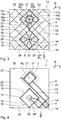
- a measuring device 1 For measuring a test object 2, a measuring device 1 has a transmitter-receiver unit 3, a first collimator-focusing arrangement 4, a mirror arrangement 5, a test object receiving area 6 and a control unit 7.
- the measuring device 1 according to the Fig. 1 and Fig. 2 is used in particular for the measurement of test objects 2 with a rectangular cross-section.
- the test object 2, which in Fig. 2 is shown, has a hollow-rectangular contour.
- FIG. 1 and Fig. 2 For clarity, is in Fig. 1 and Fig. 2 no transmitter-receiver unit shown.
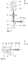
- the measuring device 1 finds the transmitter-receiver unit 3 according to Fig. 7 Application.
- the transceiver unit 3a according to FIG Fig. 8 apply in the measuring device 1, without the basic operation of the measuring device 1 changes.
- FIGS. 7 and 8 show in detail possible embodiments of the transmitter-receiver unit 3 and 3a.
- Both embodiments of the transceiver unit 3 and 3a each include a transmitter 9 for emitting radiation S in an xy plane E xy starting from a beam spot SP.
- the emitted radiation is denoted by S from the transmitter 9 to the test object 2 below.
- the radiation reflected on the test object 2 is subsequently designated by the test object 2 to a receiver 10 by R.
- the receiver 10 is used to detect the reflected on the test object 2 Radiation R.
- the detected radiation R is evaluated by means of the control unit 7.
- the transmitter 9 and the receiver 10 are arranged in a z-direction at a distance from the xy plane E xy .
- the transmitter 9 and the receiver 10 are arranged along a first z-axis Z 1 , which runs parallel to the z-direction through the beam spot SP.
- the transmitter-receiver unit 3 is designed such that the emitted radiation R in the xy plane E xy is rotatable about the beam spot SP.
- the transmitter-receiver unit 3 has a rotation mirror 11 which is rotatable about an axis of rotation 12 perpendicular to the xy plane E xy through the beam spot SP.
- the axis of rotation 12 coincides with the first z-axis Z 1 .
- the rotation mirror 11 is tilted by a tilt angle ⁇ ⁇ of 45 ° with respect to the xy plane E xy .
- the rotational movement of the rotary mirror 11 about the axis of rotation 12 is advantageously a continuous rotational movement along a direction of rotation.
- the direction of rotation is in Fig. 7 illustrated by the directional arrow 13.
- the transmitter 9 and the receiver 10 are in the embodiment shown, the transmitter-receiver unit 3 according to Fig. 7 immovable.
- the radiation S emitted by the transmitter 9 is focused from the z-direction coming by means of a focusing means 8 on the beam spot SP.
- the rotation mirror 11 directs the radiation S coming from the z direction into the xy plane E xy , the radiation S rotating through the rotation mirror 11 through 360 ° about the rotation axis 12.
- This structure of the transceiver unit 3 is easy to implement, stable and takes up little space, so that constructions with small maximum diameters of the test object 2 can be implemented.
- the transmitter-receiver unit 3 is designed such that the electromagnetic radiation S, R having a frequency in the range of 0.01 THz to 50 THz, in particular from 0.05 THz to 20 THz, and in particular from 0.1 THz to 10 THz can be emitted or detected.
- the radiation S is preferably emitted in pulsed form, that is to say generates THz pulses.
- the transmitter-receiver unit 3a is in contrast to the transmitter-receiver unit 3 after Fig. 7 no rotation mirror provided.
- the transmitter-receiver unit 3a is designed such that it is rotatable as a whole about the axis of rotation 12 in the beam spot SP.
- the transmitter 9 and the receiver 10 are thus movable.
- the rotational movement of the transmitter-receiver unit 3a about the axis of rotation 12 is advantageously a continuous rotational movement along the direction of rotation 13.
- a rotary coupling for connecting optical and electrical signals to the transceiver unit 3a.
- Both embodiments of the transmitter-receiver units 3, 3a can be used in the measuring device 1 according to the invention without the functioning of the measuring device 1 according to the invention changing.
- the first collimator-focusing arrangement 4 comprises collimator-focusing elements 14, 15, 16, 17 for converting the emitted radiation S into collimated radiation S and for focusing the reflected radiation R into the beam spot SP.
- the collimator-focusing elements 14, 15, 16, 17 are arranged such that in each case two adjacent collimator-focusing elements 14, 15, 16, 17 in the xy plane E xy include an angle ⁇ KF of 90 °, so the collimator focusing elements 14, 15, 16, 17 in the xy plane E xy a collimator-focusing square 18 form. Due to the square shape, the first collimator-focusing arrangement 4 comprises a first collimator-focusing diagonal 28 and a second collimator-focusing diagonal 29.
- the collimator focusing elements 14, 15, 16, 17 are formed as lenses.
- the collimator-focusing elements 14, 15, 16, 17 are therefore referred to as lenses.
- the lenses 14, 15, 16, 17 are each arranged in the beam path between the beam spot SP and the mirror arrangement 5.
- the incident emitted radiation S is collimated by means of the lenses 14, 15, 16, 17 in the xy-plane E xy .
- beam paths can be emitted in each quadrant of the collimator-focusing square and can be collimated by the lenses 14, 15, 16, 17.
- the lenses 14, 15, 16, 17 are identical in shape and size.
- a common focus B 1 of the lenses in the xy plane E xy lies in the beam spot SP.
- the lenses 14, 15, 16, 17 are formed as plano-convex converging lenses whose convex curvature is directed in each case in the direction beam spot SP.
- the planar sides of the lenses 14, 15, 16, 17 form edges of the collimator-focusing square 18.
- the lenses 14, 15, 16, 17 each have the numerical aperture 0.71.
- a lens diameter of the lenses 14, 15, 16, 17 in the embodiment shown is 2f, where f a focal length of the lenses 14, 15, 16, 17.
- the collimator focus square has 18 edge lengths of 2f.
- the mirror arrangement 5 comprises four mirror elements 19, 20, 21, 22 for deflecting the emitted collimated radiation S and the reflected radiation R between the collimator-focusing arrangement 4 and the test object receiving area 6.
- the test object receiving area 6 Arrangement of the test object 2 lies in the xy plane E xy .
- the mirror elements 19, 20, 21, 22 are arranged such that two adjacent mirror elements 19, 20, 21, 22 enclose an angle ⁇ SE of 90 °, so that the mirror elements 19, 20, 21, 22 in FIG the xy plane E xy form a mirror rectangle 23.
- the mirror rectangle 23 is formed as a mirror square, wherein the mirror elements 19, 20, 21, 22 are identical in shape and size.
- the mirror rectangle 23 has edge lengths of 4 2 f ,
- the mirror rectangle 23 surrounds the collimator focus square 18 in the xy plane E xy .
- Mirror surfaces 24, 25, 26, 27 of the mirror elements 19, 20, 21, 22 are arranged parallel to the collimator-focusing diagonals 28, 29 of the collimator-focusing square 18.
- the design of the mirror arrangement 5 allows each beam path of the collimated radiation S to be reflected twice.
- the mirror arrangement 5 is designed such that a first of the mirror elements 19, 20, 21, 22 deflects the collimated radiation S onto a second of the mirror elements 19, 20, 21, 22, the second mirror unit Elements 19, 20, 21, 22 the radiation S deflects to the educamony Colour 6.
- the mirror arrangement 5 is further embodied in such a way that the collimated radiation S impinges on the respective first and second mirror elements 19, 20, 21, 22 at an angle of incidence .alpha..sub.IN of substantially 45.degree. Through which mirror elements 19, 20, 21, 22 a deflection of the collimated radiation S takes place depends on which quadrant of the collimator-focusing square 18 the radiation S was emitted.
- the second mirror surface 25 and the fourth mirror surface 27 are arranged parallel to each other and symmetrically with respect to the first collimator focusing diagonal 28.
- the first mirror surface 24 and the third mirror surface 26 are arranged parallel to each other and symmetrically with respect to the second collimator focusing diagonal 29.
- the first collimator focusing diagonal 28 also coincides with a side bisector 33 of the mirror square 23 formed as a mirror square.
- a lens edge 30 formed by the first lens 14 and the second lens 15 adjoins the first mirror surface 24.
- the measuring device 1 is designed in such a way that the collimated radiation S reaches the test object receiving region 6 after the reflections on the mirror arrangement 5.
- the test object receiving area 6 extends in the xy plane E xy in the form of a test object receiving square 31.
- An edge length of the test object receiving square 31 corresponds to the edge length of the collimator focusing square 18 and corresponds to twice the focal length f of the lenses 14, 15, 16, 17.
- a first inspection object shot square diagonal 32 coincides with the same side bisector 33 of the mirror rectangle 23 as the first collimator focusing diagonal 28.
- the inspection object receiving square 31 and the collimator focusing square 18 are along the Side bisecting 33 arranged adjacent to each other and fill them out exactly. This means a sum of the lengths of the first inspection object receiving square diagonal 32 and the first collimating focusing diagonal 28 corresponds to a length of the side bisector 33 of the mirror rectangle 23.
- the test object 2 is arranged for measurement within the educassenarea square 31.
- profile walls 34 of the hollow rectangular test object 2 are aligned parallel to the edges of the füraiseability-square 31. This allows the collimated radiation S to be incident perpendicular to the profile walls 34 and the reflected radiation R to travel along the same optical path in the opposite direction back to the beam spot SP, where it is detectable by the receiver 10.
- the test object receiving square 31 represents a maximum detection range. If a profile cross section of a test object 2 is completely in the test object receiving square 31, all profile walls which run parallel to edges of the test object receiving square 31 can be tested in their entirety.
- the entirety of the radiation generated by rotation and expiring successively from the beam spot SP can be subdivided into four beam bundles with an opening angle ao of 90 ° each.
- Each bundle of rays is assigned a quadrant of the collimator-focusing square 18.
- the divergent radiation emanating from the beam spot SP is collimated by means of the lenses 14, 15, 16, 17 of the first collimator-focusing arrangement 4. After the lenses 14, 15, 16, 17, all rays emitted in one quadrant of the collimator-focusing square 18 are parallel to one another. This results in four collimated beam paths.
- each beam is reflected twice by the mirror arrangement 5.
- the collimated radiation S impinges on the respective mirror element 19, 20, 21, 22 at the angle of incidence ⁇ IN of 45 °.
- the radiation collimated by the third lens 16 impinges on the second mirror element 20 at the angle of incidence ⁇ IN of 45 °, where it is reflected by the second mirror surface 25 to the third mirror element 21, where the collimated radiation S again impinges at the angle of incidence ⁇ IN of 45 °.
- the third mirror surface 26 forwards the collimated radiation S to the test object receiving region 6.
- the collimated radiation S After the reflections, the collimated radiation S impinges perpendicular to the profile walls 34 of the test object 2.
- the THz pulses from the transmitter-receiver unit 3 are thus radiated perpendicular to the test object 2.
- an emission direction of the radiation S emanating from the beam spot SP is varied by rotation of the rotation mirror 11.
- a rotation of the emitted radiation S in the direction of rotation 13 is shown.
- the individual profile walls 34 of the test object 2 are checked one after the other.
- a direction of movement of the radiation S runs counter to the direction of rotation 13, which is in particular Fig. 2 is apparent.
- the test object 2 is to be arranged such that its central longitudinal axis 35 extends along a second z-axis Z 2 through the xy plane E xy in the test object receiving region 6 and an extrusion direction of the test object 2 is parallel to the z-axis.
- the radiation R reflected on the test object 2 or the reflected THz pulses travel at least partially along the same beam paths back to the transceiver unit 3.
- the reflected radiation R is reflected twice again by means of the mirror arrangement 5 and in the direction of the receiver 10 diverted.
- the collimator-focusing arrangement 4 focuses the reflected radiation R at the common focus B 1 of the first collimator-focusing arrangement 4.
- the receiver 10 detects the focused radiation R.
- the structure of the receiver 10 is basically known. THz pulses are detected, for example, by optical sampling with femtosecond laser pulses.
- the detected radiation R is evaluated by the control unit 7.
- the hollow-rectangular test object 2 can be scanned in its entirety and measured, without any need for a rotation of the test object 2 about its central longitudinal axis 35 or a translational movement of the test object. This is particularly advantageous if a measurement of the test object 2 takes place during an extrusion process. A measurement of the test object 2 can therefore be done inline. A full measurement of the test object 2 can be achieved with only one transmitter-receiver unit 3.
- a real beam propagation of the radiation S, R is shown.
- the radiation S is emitted as described above by means of the transmitter-receiver unit 3.
- the emitted radiation S has a beam divergence.
- the radiation S, R has a divergence angle ⁇ R in the xy plane E xy . Due to the divergence angle ⁇ R , the radiation S which impinges on the lenses 14, 15, 16, 17 is adjustable and thus also a diameter of the collimated radiation S.
- the collimated radiation S does not strike the test object 2 punctually in the case of a real beam propagation. but in a measuring range. The size of the measuring range depends on the divergence angle ⁇ R.
- the radiation S or the respective THz pulse impinges perpendicularly on the profile walls 34 of the test object 2, and at the same points in time. This ensures that the reflected radiation R has a high signal quality and in particular the reflected THz pulses are not washed out and are attenuated in their amplitude.
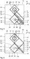
- FIG. 3 A second embodiment of the invention described.
- the measuring device 1a is used in particular for measuring test objects 2a with a hollow-cylindrical cross-section.
- Components of the measuring device 1a, which with parts of the first embodiment the measuring device 1 are identical, the same reference numerals.
- the transmitter-receiver unit 3, the first collimator-focusing arrangement 4 and the mirror arrangement 5 of the measuring device 1a are identical to the measuring device 1.
- the measuring device 1a comprises a second collimator-focusing arrangement 37 for Focusing the radiation S collimated by means of the first collimator-focusing arrangement 4 into a common test object focal point B 2 and for converting the reflected radiation R into reflected collimated radiation R.
- the second collimator focusing arrangement 37 is arranged in the test object receiving area 6 concentrically with the test object focal point B 2 .
- the second collimator-focusing arrangement 37 is formed identically to the first collimator-focusing arrangement 4 and comprises four collimator-focusing elements formed as plano-convex lenses 14a, 15a, 16a, 17a.
- the lenses 14a, 15a, 16a, 17a of the second collimator focus assembly 37 also form a collimator focus square 18a.
- the collimator focus square 18a includes a first collimator focus diagonal 28a and a second collimator focus diagonal 29a.
- the second collimator focusing arrangement 37 is arranged in the test object receiving area 6 in such a way that the first collimator focusing diagonal 28a of the second collimator focusing arrangement 37 coincides with the side bisector 33 of the square mirror rectangle 23. Put simply, the second collimator-focusing arrangement 37 in the xy plane E xy is congruent with that associated with FIG Fig. 1 and Fig. 2 Test object receiving square 31 described formed.
- a maximum detectable pipe diameter of the test object 2a is 2 (f-p) where p denotes a maximum thickness of the lenses 14a, 15a, 16a, 17a. Ideally, the lens thickness p is significantly smaller than the focal length f.
- a real beam propagation of the radiation S, R in connection with the second embodiment of the measuring device 1a is shown.
- the collimated THz radiation S is focused through the lenses 14a, 15a, 16a, 17a and directed to the test object 2a.
- a focal point is not on the test object 2a but in the test object focal point B 2 .
- every point of an incident hits Wavefront of a THz pulse at the same time and perpendicular to the concentric to the test object focus B 2 arranged test object 2a.
- the THz radiation S is always ideally reflected independently of a pipe diameter.
- a detection geometry is optimally designed for a geometry of the test object 2a.
- the radiation S incident on the test object focal point B 2 and the radiation S emanating from the beam spot SP have the same divergence angle ⁇ R , the divergence angle ⁇ R being independent of a radiation direction.
- Fig. 6 the measuring device 1a is shown, wherein emitted radiation S strikes an edge of the collimator-focusing square 18, at which the fourth lens 17 and the first lens 14 coincide to form the angle ⁇ KF of 90 °.
- the considered radiation S thus impinges on two lenses 14, 17 and is split, so that partial radiations S1 and S2 are formed, which form two measuring ranges on the test object 2a.
- Fig. 6 can be seen in this particular case, two nearly opposite areas of the test object 2a are scanned.
- a measurement signal is thus composed of reflections in these two areas.
- a superposition of the measurement signals provides information about the positioning of the test object 2a in the structure. If the reflections coincide, the test object 2a is centered.
- each of the two signal components can be uniquely attributed to the reflection from a region.
- a measuring device 1b according to the third embodiment differs from the measuring devices 1, 1a primarily by the design of a mirror assembly 39 from.
- the mirror arrangement 39 is rectangular in shape as a mirror rectangle 40.
- the mirror rectangle 40 comprises four mirror elements 41, 42, 43, 44, which together form the mirror rectangle 40.
- the mirror arrangement 39 comprises a fifth mirror element 45, which is arranged within the mirror rectangle 40.
- the mutually opposite mirror elements 41, 43 are identical in shape and size. Accordingly, the opposing mirror elements 42, 44 are identical in shape and size. However, the mirror elements 41, 43 differ in edge length from the mirror elements 42, 44.
- the fifth mirror element 45 extends parallel to the mirror elements 42, 44 between them.
- the radiation S between the first collimator focusing arrangement 4 and the inspection object receiving area 6 is reflected three times. In this case, a length of the beam path 10f.
- first collimator-focusing arrangement 4 and test object receiving area 6 it is also conceivable in further alternative embodiments to provide more than two or three reflections between first collimator-focusing arrangement 4 and test object receiving area 6. Furthermore, it is also possible in principle for the first collimator-focusing arrangement 4 and / or the second collimator-focusing arrangement 37 to be designed as collimator-focusing polygons having more than four corners. However, a majority of test objects to be measured has edges that are perpendicular to each other. Therefore, in particular, the embodiments of the measuring device 1 and the measuring device 1b form preferred solutions.
Landscapes
- Engineering & Computer Science (AREA)
- Mechanical Engineering (AREA)
- Physics & Mathematics (AREA)
- General Physics & Mathematics (AREA)
- Length Measuring Devices By Optical Means (AREA)
- Investigating Or Analysing Materials By Optical Means (AREA)
Claims (19)
- Dispositif de mesure destiné à mesurer des objets d'essai avec- une unité émettrice-réceptrice (3 ; 3a) avec-- un émetteur (9) destiné à émettre un rayonnement Térahertz (S) dans un plan x-y (Exy) à partir d'un point de faisceau (SP) et-- un récepteur associé (10) destiné à détecter un rayonnement Térahertz (R) réfléchi par un objet d'essai (2 ; 2a),- un premier agencement de collimation et de focalisation (4)-- avec des éléments de collimation et de focalisation (14, 15, 16, 17) destinés à convertir le rayonnement Térahertz (S) émis en rayonnement collimaté et à focaliser le rayonnement Térahertz (S) dans le point de faisceau (SP),-- les éléments de collimation et de focalisation (14, 15, 16, 17) étant disposés de telle sorte que deux éléments de collimation et de focalisation (14, 15, 16, 17) voisins dans le plan x-y (Exy) forment entre eux un angle (αKF) de 90°, de façon que les éléments de collimation et de focalisation (14, 15, 16, 17) forment un carré de collimation et de focalisation (18),- un point focal commun (B1) des éléments de collimation et de focalisation (14, 15, 16, 17) se situant dans le plan x-y (Exy) dans le point de faisceau (SP),- une zone de réception de l'objet d'essai (6) située dans le plan x-y (Exy) pour y disposer l'objet d'essai (2 ; 2a),- au moins un ensemble de miroirs (5 ; 39)-- avec des éléments miroir (19, 20, 21, 22 ; 41, 42, 42, 43, 44) destinés à réorienter le rayonnement Térahertz (S) collimaté et le rayonnement Térahertz (S) réfléchi entre l'agencement de collimation et de focalisation (4) et la zone de réception de l'objet d'essai (6),- les éléments miroir (19, 20, 21, 22 ; 41, 42, 43, 44) étant disposés de telle sorte que deux éléments miroirs (19, 20, 21, 22 ;41, 43, 44) forment respectivement un angle de 90° entre eux dans le plan x-y (Exy), de façon que les éléments miroir (19, 20, 21, 22 ; 41, 43 ,44) forment un rectangle de miroirs (23, 40),-- des surfaces réfléchissantes (24, 25, 26, 27) du rectangle de miroirs (23, 40) étant parallèles à une diagonale de collimation et de focalisation (28, 29) du carré de collimation et de focalisation (18),-- les éléments de collimation et de focalisation (14, 15, 16, 17) se situant à l'intérieur du rectangle de miroirs (23, 40) et- une unité de commande (7) destinée à évaluer le rayonnement Térahertz (R) détecté.
- Dispositif de mesure suivant la revendication 1, caractérisé en ce que deux éléments de collimation et de focalisation (14, 15, 16, 17) voisins sont perpendiculaires, l'un par rapport à l'autre, dans le plan x-y (Exy) et en ce qu'en plus deux éléments miroir (19, 20, 21, 22 ; 41, 42, 43, 44) voisins sont perpendiculaires l'un par rapport à l'autre dans le plan x-y (Exy).
- Dispositif de mesure suivant la revendication 1, caractérisé en ce que les éléments de collimation et de focalisation (14, 15, 16, 17) sont conçus identiques, notamment en forme et/ou en taille.
- Dispositif de mesure suivant une quelconque des revendications précédentes, caractérisé en ce que les éléments de collimation et de focalisation (14, 15, 16, 17) sont conçus comme lentilles.
- Dispositif de mesure suivant une quelconque des revendications précédentes, caractérisé en ce que les éléments miroir (19, 20, 21, 22) sont conçus identiques, notamment en forme et/ou en taille.
- Dispositif de mesure suivant une quelconque des revendications précédentes, caractérisé en ce que l'agencement de miroirs (5, 39) est conçu de telle sorte qu'un premier élément miroir (19, 20, 21, 22 ; 41, 42, 43, 44) réoriente le rayonnement collimaté (S) vers un second élément miroir (19, 20, 21, 22 ;41, 42, 43, 44), le second élément miroir (19, 20, 21, 22 ;41, 42, 43, 44) réorientant le rayonnement (S) vers la zone de réception de l'objet d'essai (6).
- Dispositif de mesure suivant la revendication 6, caractérisé en ce que l'agencement de miroirs (5 ; 39) est conçu de telle sorte que le rayonnement collimaté (S) frappe le premier élément miroir (19, 20, 21, 22 ;41, 42, 43, 44) et le second élément miroir (19, 20, 21, 22 ; 41, 42, 43, 44) avec un angle d'incidence (αEIN) de 45°.
- Dispositif de mesure suivant une quelconque des revendications précédentes, caractérisé en ce que l'unité émettrice-réceptrice (3 ; 3a) est conçue de telle sorte que le rayonnement émis (S) dans le plan x-y (E-xy) est rotatif autour du point de faisceau (SP).
- Dispositif de mesure suivant la revendication 8, caractérisé en ce que l'unité émettrice-réceptrice (3 ; 31) est conçue de telle sorte qu'elle est disposée dans le point de faisceau (SP) de façon rotative autour d'un axe de rotation (12).
- Dispositif de mesure suivant la revendication 8, caractérisé en ce que l'unité émettrice-réceptrice (3 ; 3a) présente un miroir de rotation (11) qui est rotatif autour d'un axe de rotation (12) s'étendant à travers le point de faisceau (SP) de façon perpendiculaire au plan x-y (Exy).
- Dispositif de mesure suivant la revendication 10, caractérisé en ce que le miroir de rotation (11) est basculé autour d'un angle d'inclinaison (αK) de 45° par rapport au plan x-y (Exy).
- Dispositif de mesure suivant une quelconque des revendications précédentes, caractérisé en ce que dans la zone de réception de l'objet d'essai (6) un second agencement de collimation et de focalisation (37) est disposé de façon concentrique par rapport à un point focal de l'objet d'essai (B2).
- Dispositif de mesure suivant la revendication 12, caractérisé en ce que le premier agencement de collimation et de focalisation (4) et le second agencement de collimation et de focalisation (37) sont conçus identiques.
- Dispositif de mesure suivant la revendication 12 ou 13, caractérisé en ce que respectivement une diagonale de collimation et de focalisation (28 ; 32) du premier agencement de collimation et de focalisation (4) et du second agencement de collimation et de focalisation (37) coïncide avec une médiane (33) du rectangle de miroirs (23).
- Dispositif de mesure suivant une quelconque des revendications précédentes, caractérisé en ce que l'unité de commande (6) est conçue pour mesurer l'objet d'essai au moyen du rayonnement Térahertz sur la base de la mesure d'une différence de temps de trajet du rayonnement Térahertz qui est réfléchi par des couches limites, p.ex. une paroi externe de tube, une paroi interne de tube et des couches de matériau adjacentes l'une à l'autre à l'intérieur de l'objet d'essai (2).
- Procédé de mesure d'objets d'essai (2, 2a) comprenant les étapes suivantes qui consistent à :- fournir un dispositif de mesure (1 ; 1a ; 1b) suivant au moins une des revendications 1 à 14,- disposer un objet d'essai (2; 2a) de telle sorte que l'axe longitudinal central (35, 35a) de celui-ci s'étende à travers le plan x-y (Exy) dans la zone de réception de l'objet d'essai (6),- émettre un rayonnement Térahertz au moyen d'un émetteur (9),- collimater le rayonnement Térahertz (S) émis pour convertir le rayonnement Térahertz (S) émis en un rayonnement Térahertz collimaté au moyen du premier agencement de collimation et de focalisation (4),- réorienter le rayonnement Térahertz (S) collimaté au moyen de l'ensemble de miroirs (5, 39) vers la zone de réception de l'objet d'essai (6),- réfléchir le rayonnement Térahertz (S) collimaté par l'objet d'essai (2, 2a)- réorienter le rayonnement Térahertz (R) réfléchi au moyen de l'ensemble de miroirs (5, 39) dans la direction du récepteur (10),- focaliser le rayonnement Térahertz (R) réfléchi au moyen du premier agencement de collimation et de focalisation (4) sur le point focal commun (B1) des éléments de collimation et de focalisation (14, 15, 16, 17),- détecter le rayonnement Téraherz (R) focalisé au moyen de l'émetteur (10), et- évaluer le rayonnement Térahertz (R) détecté.
- Procédé suivant la revendication 16, caractérisé en ce que le rayonnement Térahertz (S) émis est en rotation autour du point de faisceau (SP).
- Procédé suivant la revendication 16 ou 17, caractérisé en ce que le rayonnement Térahertz (S) émis et le rayonnement Térahertz (R) réfléchi ont au moins partiellement la même trajectoire de faisceau.
- Procédé suivant une des revendications 16 à 18, caractérisé en ce qu'un objet d'essai (2) en matière artificielle est mesuré, en mesurant une différence de temps de trajet du rayonnement Térahertz qui est réfléchi par des couches limites, notamment des surfaces de l'objet d'essai (2), p.ex. une paroi externe de tube et/ou une paroi interne de tube et/ou des couches de matériau adjacentes l'une à l'autre à l'intérieur de l'objet d'essai (2).
Applications Claiming Priority (2)
| Application Number | Priority Date | Filing Date | Title |
|---|---|---|---|
| DE102014214046.3A DE102014214046B3 (de) | 2014-07-18 | 2014-07-18 | Messvorrichtung und Verfahren zur Vermessung von Prüfobjekten |
| PCT/DE2015/100221 WO2016008470A1 (fr) | 2014-07-18 | 2015-06-03 | Dispositif de mesure et procédé de mesure d'objets à contrôler |
Publications (2)
| Publication Number | Publication Date |
|---|---|
| EP3169505A1 EP3169505A1 (fr) | 2017-05-24 |
| EP3169505B1 true EP3169505B1 (fr) | 2018-04-25 |
Family
ID=53783534
Family Applications (1)
| Application Number | Title | Priority Date | Filing Date |
|---|---|---|---|
| EP15747367.9A Active EP3169505B1 (fr) | 2014-07-18 | 2015-06-03 | Dispositif de mesure et procédé de mesure d'objets à contrôler |
Country Status (3)
| Country | Link |
|---|---|
| EP (1) | EP3169505B1 (fr) |
| DE (1) | DE102014214046B3 (fr) |
| WO (1) | WO2016008470A1 (fr) |
Cited By (1)
| Publication number | Priority date | Publication date | Assignee | Title |
|---|---|---|---|---|
| WO2024154070A1 (fr) * | 2023-01-18 | 2024-07-25 | Helmut Fischer GmbH Institut für Elektronik und Messtechnik | Dispositif de mesure ainsi que dispositif de positionnement et procédé de positionnement relatif du dispositif de mesure au moyen d'un dispositif à thx |
Families Citing this family (6)
| Publication number | Priority date | Publication date | Assignee | Title |
|---|---|---|---|---|
| DE102015122205B4 (de) | 2015-12-18 | 2022-11-03 | Inoex Gmbh | Terahertz-Messverfahren und Terahertz-Messvorrichtung zum Ermitteln einer Schichtdicke oder eines Abstandes eines Messobjektes |
| DE102016109087A1 (de) * | 2016-05-18 | 2017-11-23 | Inoex Gmbh | Verfahren zur Regelung und Steuerung von Rohrextrusionsanlagen |
| DE102018122965B4 (de) | 2018-09-19 | 2021-10-14 | INOEX GmbH Innovationen und Ausrüstungen für die Extrusionstechnik | THz-Messgerät und THz-Messverfahren zur Ermittlung von Fehlstellen in Messobjekten |
| CN109683191B (zh) * | 2018-11-26 | 2023-07-21 | 山东航天电子技术研究所 | 一种x射线准直器的测试方法 |
| DE102018131370A1 (de) | 2018-12-07 | 2020-06-10 | INOEX GmbH Innovationen und Ausrüstungen für die Extrusionstechnik | Messsystem und Verfahren zur Vermessung eines Messobjektes, insbesondere eines Kunststoff-Profils |
| DE102021125111A1 (de) | 2021-09-28 | 2023-03-30 | CiTEX Holding GmbH | THz-Messvorrichtung und THz-Messverfahren zum Vermessen eines geförderten Prüfobjektes |
Family Cites Families (7)
| Publication number | Priority date | Publication date | Assignee | Title |
|---|---|---|---|---|
| GB2198858B (en) * | 1984-03-02 | 1989-05-24 | British Aerospace | Surveillance apparatus |
| WO1995007471A1 (fr) * | 1993-09-07 | 1995-03-16 | Laserscore, Inc. | Procede et appareil de detection de la presence et de localisation d'un objet dans un champ |
| JP3477170B2 (ja) * | 1997-11-19 | 2003-12-10 | イネックス ゲゼルシャフト ミット ベシュレンクテル ハフツング | 超音波信号を用いて連続的に移動するプラスチックのストリップ又は管の中の欠陥を検出しかつ/又はそれらの壁厚を測定するための装置 |
| US8054461B2 (en) * | 2008-09-30 | 2011-11-08 | Hewlett-Packard Development Company, L.P. | Systems for performing Raman spectroscopy |
| JP2011099816A (ja) * | 2009-11-09 | 2011-05-19 | Sony Corp | 集光レンズ及び3次元距離測定装置 |
| DE102011078539A1 (de) * | 2011-06-08 | 2012-12-13 | Rohde & Schwarz Gmbh & Co. Kg | Verfahren und Vorrichtung zur Erweiterung der Ausleuchtung eines Prüfobjekts |
| GB201300016D0 (en) * | 2013-01-02 | 2013-02-13 | Proton Products Ltd | Measurement of industrial products manufactured by extrusion techniques |
-
2014
- 2014-07-18 DE DE102014214046.3A patent/DE102014214046B3/de not_active Expired - Fee Related
-
2015
- 2015-06-03 WO PCT/DE2015/100221 patent/WO2016008470A1/fr not_active Ceased
- 2015-06-03 EP EP15747367.9A patent/EP3169505B1/fr active Active
Non-Patent Citations (1)
| Title |
|---|
| None * |
Cited By (1)
| Publication number | Priority date | Publication date | Assignee | Title |
|---|---|---|---|---|
| WO2024154070A1 (fr) * | 2023-01-18 | 2024-07-25 | Helmut Fischer GmbH Institut für Elektronik und Messtechnik | Dispositif de mesure ainsi que dispositif de positionnement et procédé de positionnement relatif du dispositif de mesure au moyen d'un dispositif à thx |
Also Published As
| Publication number | Publication date |
|---|---|
| WO2016008470A1 (fr) | 2016-01-21 |
| DE102014214046B3 (de) | 2015-10-01 |
| EP3169505A1 (fr) | 2017-05-24 |
Similar Documents
| Publication | Publication Date | Title |
|---|---|---|
| EP3169505B1 (fr) | Dispositif de mesure et procédé de mesure d'objets à contrôler | |
| EP3071927B1 (fr) | Dispositif de mesure et procédé de mesurage d'objets à contrôler | |
| EP3443297B1 (fr) | Dispositif de mesure térahertz pour la mesure d'objets à contrôler et procédé de mesure térahertz | |
| EP3704442B1 (fr) | Procédé de mesure en térahertz et dispositif de mesure en térahertz pour le mesurage de tuyaux | |
| WO2016139155A1 (fr) | Dispositif et procédé de mesure du diamètre et/ou de l'épaisseur de paroi d'une barre de coulée | |
| DE10341548A1 (de) | Optoelektronische Erfassungseinrichtung | |
| DE10051302C2 (de) | Laserentfernungsmessgerät für den Nah- und Fernbereich mit speziellem Empfänger | |
| WO2015027994A1 (fr) | Dispositif de mesure de réflexions sur des objets à contrôler et procédé de mesure d'un rayonnement réfléchi par des objets à contrôler | |
| EP3161410B1 (fr) | Dispositif de mesure et procédé de mesure d'objets à contrôler | |
| DE69602205T2 (de) | Vorrichtung zur zerstörungsfreien prüfung eines länglisches werkstücks mit ultraschall | |
| DE202006012038U1 (de) | Optisches Entfernungsmessgerät | |
| DE69317702T2 (de) | Optische Winkelmessanordnung | |
| EP3827215B1 (fr) | Dispositif de détermination du diamètre et/ou du contour extérieur d'un objet en forme de barre | |
| EP3349042B1 (fr) | Capteur de surveillance et véhicule relié par le plancher | |
| WO2024068294A1 (fr) | Procédé de mesure pour réflectométrie euv, et réflectomètre euv | |
| DE3408106C2 (fr) | ||
| WO2016188515A1 (fr) | Dispositif de mesure térahertz et procédé de mesurage d'objets à contrôler au moyen d'un rayonnement térahertz | |
| DE102024131501B3 (de) | Entfernungsmesser zum erfassen von objekten | |
| DE102010037403B4 (de) | Anordnung zur Messung von Verbiegungen | |
| DE3219388C2 (de) | Optisch-elektrische Meßeinrichtung zum Messen der Lage und/oder der Abmessung von Gegenständen | |
| DE202024106195U1 (de) | Entfernungsmesser zum Erfassen von Objekten | |
| EP4446695A1 (fr) | Procédé de mesure thz et dispositif de mesure thz permettant de mesurer un brin | |
| DE102022123851A1 (de) | Radar zur Messung eines Abstands zu einem Messobjekt nach dem Laufzeitprinzip | |
| WO2025067954A1 (fr) | Dispositif de mesure lidar pour détecter un objet | |
| DE202020101894U1 (de) | Optoelektronischer Sensor mit Blende |
Legal Events
| Date | Code | Title | Description |
|---|---|---|---|
| PUAI | Public reference made under article 153(3) epc to a published international application that has entered the european phase |
Free format text: ORIGINAL CODE: 0009012 |
|
| 17P | Request for examination filed |
Effective date: 20170105 |
|
| AK | Designated contracting states |
Kind code of ref document: A1 Designated state(s): AL AT BE BG CH CY CZ DE DK EE ES FI FR GB GR HR HU IE IS IT LI LT LU LV MC MK MT NL NO PL PT RO RS SE SI SK SM TR |
|
| AX | Request for extension of the european patent |
Extension state: BA ME |
|
| DAV | Request for validation of the european patent (deleted) | ||
| DAX | Request for extension of the european patent (deleted) | ||
| GRAP | Despatch of communication of intention to grant a patent |
Free format text: ORIGINAL CODE: EPIDOSNIGR1 |
|
| GRAS | Grant fee paid |
Free format text: ORIGINAL CODE: EPIDOSNIGR3 |
|
| INTG | Intention to grant announced |
Effective date: 20180116 |
|
| GRAA | (expected) grant |
Free format text: ORIGINAL CODE: 0009210 |
|
| AK | Designated contracting states |
Kind code of ref document: B1 Designated state(s): AL AT BE BG CH CY CZ DE DK EE ES FI FR GB GR HR HU IE IS IT LI LT LU LV MC MK MT NL NO PL PT RO RS SE SI SK SM TR |
|
| REG | Reference to a national code |
Ref country code: GB Ref legal event code: FG4D Free format text: NOT ENGLISH |
|
| REG | Reference to a national code |
Ref country code: CH Ref legal event code: EP |
|
| REG | Reference to a national code |
Ref country code: AT Ref legal event code: REF Ref document number: 992409 Country of ref document: AT Kind code of ref document: T Effective date: 20180515 |
|
| REG | Reference to a national code |
Ref country code: IE Ref legal event code: FG4D Free format text: LANGUAGE OF EP DOCUMENT: GERMAN |
|
| REG | Reference to a national code |
Ref country code: DE Ref legal event code: R096 Ref document number: 502015004048 Country of ref document: DE |
|
| REG | Reference to a national code |
Ref country code: NL Ref legal event code: MP Effective date: 20180425 |
|
| REG | Reference to a national code |
Ref country code: LT Ref legal event code: MG4D |
|
| PG25 | Lapsed in a contracting state [announced via postgrant information from national office to epo] |
Ref country code: NL Free format text: LAPSE BECAUSE OF FAILURE TO SUBMIT A TRANSLATION OF THE DESCRIPTION OR TO PAY THE FEE WITHIN THE PRESCRIBED TIME-LIMIT Effective date: 20180425 |
|
| PG25 | Lapsed in a contracting state [announced via postgrant information from national office to epo] |
Ref country code: ES Free format text: LAPSE BECAUSE OF FAILURE TO SUBMIT A TRANSLATION OF THE DESCRIPTION OR TO PAY THE FEE WITHIN THE PRESCRIBED TIME-LIMIT Effective date: 20180425 Ref country code: SE Free format text: LAPSE BECAUSE OF FAILURE TO SUBMIT A TRANSLATION OF THE DESCRIPTION OR TO PAY THE FEE WITHIN THE PRESCRIBED TIME-LIMIT Effective date: 20180425 Ref country code: LT Free format text: LAPSE BECAUSE OF FAILURE TO SUBMIT A TRANSLATION OF THE DESCRIPTION OR TO PAY THE FEE WITHIN THE PRESCRIBED TIME-LIMIT Effective date: 20180425 Ref country code: PL Free format text: LAPSE BECAUSE OF FAILURE TO SUBMIT A TRANSLATION OF THE DESCRIPTION OR TO PAY THE FEE WITHIN THE PRESCRIBED TIME-LIMIT Effective date: 20180425 Ref country code: FI Free format text: LAPSE BECAUSE OF FAILURE TO SUBMIT A TRANSLATION OF THE DESCRIPTION OR TO PAY THE FEE WITHIN THE PRESCRIBED TIME-LIMIT Effective date: 20180425 Ref country code: NO Free format text: LAPSE BECAUSE OF FAILURE TO SUBMIT A TRANSLATION OF THE DESCRIPTION OR TO PAY THE FEE WITHIN THE PRESCRIBED TIME-LIMIT Effective date: 20180725 Ref country code: BG Free format text: LAPSE BECAUSE OF FAILURE TO SUBMIT A TRANSLATION OF THE DESCRIPTION OR TO PAY THE FEE WITHIN THE PRESCRIBED TIME-LIMIT Effective date: 20180725 |
|
| REG | Reference to a national code |
Ref country code: DE Ref legal event code: R079 Ref document number: 502015004048 Country of ref document: DE Free format text: PREVIOUS MAIN CLASS: B29C0047920000 Ipc: B29C0048920000 |
|
| PG25 | Lapsed in a contracting state [announced via postgrant information from national office to epo] |
Ref country code: RS Free format text: LAPSE BECAUSE OF FAILURE TO SUBMIT A TRANSLATION OF THE DESCRIPTION OR TO PAY THE FEE WITHIN THE PRESCRIBED TIME-LIMIT Effective date: 20180425 Ref country code: LV Free format text: LAPSE BECAUSE OF FAILURE TO SUBMIT A TRANSLATION OF THE DESCRIPTION OR TO PAY THE FEE WITHIN THE PRESCRIBED TIME-LIMIT Effective date: 20180425 Ref country code: GR Free format text: LAPSE BECAUSE OF FAILURE TO SUBMIT A TRANSLATION OF THE DESCRIPTION OR TO PAY THE FEE WITHIN THE PRESCRIBED TIME-LIMIT Effective date: 20180726 Ref country code: HR Free format text: LAPSE BECAUSE OF FAILURE TO SUBMIT A TRANSLATION OF THE DESCRIPTION OR TO PAY THE FEE WITHIN THE PRESCRIBED TIME-LIMIT Effective date: 20180425 |
|
| PG25 | Lapsed in a contracting state [announced via postgrant information from national office to epo] |
Ref country code: PT Free format text: LAPSE BECAUSE OF FAILURE TO SUBMIT A TRANSLATION OF THE DESCRIPTION OR TO PAY THE FEE WITHIN THE PRESCRIBED TIME-LIMIT Effective date: 20180827 |
|
| REG | Reference to a national code |
Ref country code: DE Ref legal event code: R097 Ref document number: 502015004048 Country of ref document: DE |
|
| PG25 | Lapsed in a contracting state [announced via postgrant information from national office to epo] |
Ref country code: SK Free format text: LAPSE BECAUSE OF FAILURE TO SUBMIT A TRANSLATION OF THE DESCRIPTION OR TO PAY THE FEE WITHIN THE PRESCRIBED TIME-LIMIT Effective date: 20180425 Ref country code: DK Free format text: LAPSE BECAUSE OF FAILURE TO SUBMIT A TRANSLATION OF THE DESCRIPTION OR TO PAY THE FEE WITHIN THE PRESCRIBED TIME-LIMIT Effective date: 20180425 Ref country code: EE Free format text: LAPSE BECAUSE OF FAILURE TO SUBMIT A TRANSLATION OF THE DESCRIPTION OR TO PAY THE FEE WITHIN THE PRESCRIBED TIME-LIMIT Effective date: 20180425 Ref country code: RO Free format text: LAPSE BECAUSE OF FAILURE TO SUBMIT A TRANSLATION OF THE DESCRIPTION OR TO PAY THE FEE WITHIN THE PRESCRIBED TIME-LIMIT Effective date: 20180425 Ref country code: CZ Free format text: LAPSE BECAUSE OF FAILURE TO SUBMIT A TRANSLATION OF THE DESCRIPTION OR TO PAY THE FEE WITHIN THE PRESCRIBED TIME-LIMIT Effective date: 20180425 |
|
| REG | Reference to a national code |
Ref country code: CH Ref legal event code: PL |
|
| PG25 | Lapsed in a contracting state [announced via postgrant information from national office to epo] |
Ref country code: IT Free format text: LAPSE BECAUSE OF FAILURE TO SUBMIT A TRANSLATION OF THE DESCRIPTION OR TO PAY THE FEE WITHIN THE PRESCRIBED TIME-LIMIT Effective date: 20180425 Ref country code: SM Free format text: LAPSE BECAUSE OF FAILURE TO SUBMIT A TRANSLATION OF THE DESCRIPTION OR TO PAY THE FEE WITHIN THE PRESCRIBED TIME-LIMIT Effective date: 20180425 |
|
| PLBE | No opposition filed within time limit |
Free format text: ORIGINAL CODE: 0009261 |
|
| STAA | Information on the status of an ep patent application or granted ep patent |
Free format text: STATUS: NO OPPOSITION FILED WITHIN TIME LIMIT |
|
| REG | Reference to a national code |
Ref country code: BE Ref legal event code: MM Effective date: 20180630 |
|
| REG | Reference to a national code |
Ref country code: IE Ref legal event code: MM4A |
|
| PG25 | Lapsed in a contracting state [announced via postgrant information from national office to epo] |
Ref country code: MC Free format text: LAPSE BECAUSE OF FAILURE TO SUBMIT A TRANSLATION OF THE DESCRIPTION OR TO PAY THE FEE WITHIN THE PRESCRIBED TIME-LIMIT Effective date: 20180425 Ref country code: LU Free format text: LAPSE BECAUSE OF NON-PAYMENT OF DUE FEES Effective date: 20180603 |
|
| 26N | No opposition filed |
Effective date: 20190128 |
|
| PG25 | Lapsed in a contracting state [announced via postgrant information from national office to epo] |
Ref country code: CH Free format text: LAPSE BECAUSE OF NON-PAYMENT OF DUE FEES Effective date: 20180630 Ref country code: IE Free format text: LAPSE BECAUSE OF NON-PAYMENT OF DUE FEES Effective date: 20180603 Ref country code: LI Free format text: LAPSE BECAUSE OF NON-PAYMENT OF DUE FEES Effective date: 20180630 Ref country code: FR Free format text: LAPSE BECAUSE OF NON-PAYMENT OF DUE FEES Effective date: 20180625 |
|
| PG25 | Lapsed in a contracting state [announced via postgrant information from national office to epo] |
Ref country code: BE Free format text: LAPSE BECAUSE OF NON-PAYMENT OF DUE FEES Effective date: 20180630 Ref country code: SI Free format text: LAPSE BECAUSE OF FAILURE TO SUBMIT A TRANSLATION OF THE DESCRIPTION OR TO PAY THE FEE WITHIN THE PRESCRIBED TIME-LIMIT Effective date: 20180425 |
|
| PG25 | Lapsed in a contracting state [announced via postgrant information from national office to epo] |
Ref country code: AL Free format text: LAPSE BECAUSE OF FAILURE TO SUBMIT A TRANSLATION OF THE DESCRIPTION OR TO PAY THE FEE WITHIN THE PRESCRIBED TIME-LIMIT Effective date: 20180425 |
|
| PG25 | Lapsed in a contracting state [announced via postgrant information from national office to epo] |
Ref country code: MT Free format text: LAPSE BECAUSE OF FAILURE TO SUBMIT A TRANSLATION OF THE DESCRIPTION OR TO PAY THE FEE WITHIN THE PRESCRIBED TIME-LIMIT Effective date: 20180425 |
|
| PG25 | Lapsed in a contracting state [announced via postgrant information from national office to epo] |
Ref country code: TR Free format text: LAPSE BECAUSE OF FAILURE TO SUBMIT A TRANSLATION OF THE DESCRIPTION OR TO PAY THE FEE WITHIN THE PRESCRIBED TIME-LIMIT Effective date: 20180425 |
|
| PG25 | Lapsed in a contracting state [announced via postgrant information from national office to epo] |
Ref country code: MK Free format text: LAPSE BECAUSE OF NON-PAYMENT OF DUE FEES Effective date: 20180425 Ref country code: HU Free format text: LAPSE BECAUSE OF FAILURE TO SUBMIT A TRANSLATION OF THE DESCRIPTION OR TO PAY THE FEE WITHIN THE PRESCRIBED TIME-LIMIT; INVALID AB INITIO Effective date: 20150603 Ref country code: CY Free format text: LAPSE BECAUSE OF FAILURE TO SUBMIT A TRANSLATION OF THE DESCRIPTION OR TO PAY THE FEE WITHIN THE PRESCRIBED TIME-LIMIT Effective date: 20180425 |
|
| PG25 | Lapsed in a contracting state [announced via postgrant information from national office to epo] |
Ref country code: IS Free format text: LAPSE BECAUSE OF FAILURE TO SUBMIT A TRANSLATION OF THE DESCRIPTION OR TO PAY THE FEE WITHIN THE PRESCRIBED TIME-LIMIT Effective date: 20180825 |
|
| REG | Reference to a national code |
Ref country code: AT Ref legal event code: MM01 Ref document number: 992409 Country of ref document: AT Kind code of ref document: T Effective date: 20200603 |
|
| PG25 | Lapsed in a contracting state [announced via postgrant information from national office to epo] |
Ref country code: AT Free format text: LAPSE BECAUSE OF NON-PAYMENT OF DUE FEES Effective date: 20200603 |
|
| PGFP | Annual fee paid to national office [announced via postgrant information from national office to epo] |
Ref country code: GB Payment date: 20250620 Year of fee payment: 11 |
|
| PGFP | Annual fee paid to national office [announced via postgrant information from national office to epo] |
Ref country code: DE Payment date: 20250801 Year of fee payment: 11 |