EP3170208B1 - Beschichtungsmaterialien und verfahren für verbesserte zuverlässigkeit - Google Patents
Beschichtungsmaterialien und verfahren für verbesserte zuverlässigkeit Download PDFInfo
- Publication number
- EP3170208B1 EP3170208B1 EP15821993.1A EP15821993A EP3170208B1 EP 3170208 B1 EP3170208 B1 EP 3170208B1 EP 15821993 A EP15821993 A EP 15821993A EP 3170208 B1 EP3170208 B1 EP 3170208B1
- Authority
- EP
- European Patent Office
- Prior art keywords
- coating
- glass
- group
- substituted
- solar module
- Prior art date
- Legal status (The legal status is an assumption and is not a legal conclusion. Google has not performed a legal analysis and makes no representation as to the accuracy of the status listed.)
- Active
Links
Images


Classifications
-
- H—ELECTRICITY
- H10—SEMICONDUCTOR DEVICES; ELECTRIC SOLID-STATE DEVICES NOT OTHERWISE PROVIDED FOR
- H10F—INORGANIC SEMICONDUCTOR DEVICES SENSITIVE TO INFRARED RADIATION, LIGHT, ELECTROMAGNETIC RADIATION OF SHORTER WAVELENGTH OR CORPUSCULAR RADIATION
- H10F19/00—Integrated devices, or assemblies of multiple devices, comprising at least one photovoltaic cell covered by group H10F10/00, e.g. photovoltaic modules
- H10F19/80—Encapsulations or containers for integrated devices, or assemblies of multiple devices, having photovoltaic cells
-
- C—CHEMISTRY; METALLURGY
- C09—DYES; PAINTS; POLISHES; NATURAL RESINS; ADHESIVES; COMPOSITIONS NOT OTHERWISE PROVIDED FOR; APPLICATIONS OF MATERIALS NOT OTHERWISE PROVIDED FOR
- C09D—COATING COMPOSITIONS, e.g. PAINTS, VARNISHES OR LACQUERS; FILLING PASTES; CHEMICAL PAINT OR INK REMOVERS; INKS; CORRECTING FLUIDS; WOODSTAINS; PASTES OR SOLIDS FOR COLOURING OR PRINTING; USE OF MATERIALS THEREFOR
- C09D5/00—Coating compositions, e.g. paints, varnishes or lacquers, characterised by their physical nature or the effects produced; Filling pastes
- C09D5/006—Anti-reflective coatings
-
- C—CHEMISTRY; METALLURGY
- C03—GLASS; MINERAL OR SLAG WOOL
- C03C—CHEMICAL COMPOSITION OF GLASSES, GLAZES OR VITREOUS ENAMELS; SURFACE TREATMENT OF GLASS; SURFACE TREATMENT OF FIBRES OR FILAMENTS MADE FROM GLASS, MINERALS OR SLAGS; JOINING GLASS TO GLASS OR OTHER MATERIALS
- C03C17/00—Surface treatment of glass, not in the form of fibres or filaments, by coating
- C03C17/28—Surface treatment of glass, not in the form of fibres or filaments, by coating with organic material
- C03C17/30—Surface treatment of glass, not in the form of fibres or filaments, by coating with organic material with silicon-containing compounds
-
- C—CHEMISTRY; METALLURGY
- C09—DYES; PAINTS; POLISHES; NATURAL RESINS; ADHESIVES; COMPOSITIONS NOT OTHERWISE PROVIDED FOR; APPLICATIONS OF MATERIALS NOT OTHERWISE PROVIDED FOR
- C09D—COATING COMPOSITIONS, e.g. PAINTS, VARNISHES OR LACQUERS; FILLING PASTES; CHEMICAL PAINT OR INK REMOVERS; INKS; CORRECTING FLUIDS; WOODSTAINS; PASTES OR SOLIDS FOR COLOURING OR PRINTING; USE OF MATERIALS THEREFOR
- C09D183/00—Coating compositions based on macromolecular compounds obtained by reactions forming in the main chain of the macromolecule a linkage containing silicon, with or without sulfur, nitrogen, oxygen, or carbon only; Coating compositions based on derivatives of such polymers
- C09D183/04—Polysiloxanes
-
- C—CHEMISTRY; METALLURGY
- C09—DYES; PAINTS; POLISHES; NATURAL RESINS; ADHESIVES; COMPOSITIONS NOT OTHERWISE PROVIDED FOR; APPLICATIONS OF MATERIALS NOT OTHERWISE PROVIDED FOR
- C09D—COATING COMPOSITIONS, e.g. PAINTS, VARNISHES OR LACQUERS; FILLING PASTES; CHEMICAL PAINT OR INK REMOVERS; INKS; CORRECTING FLUIDS; WOODSTAINS; PASTES OR SOLIDS FOR COLOURING OR PRINTING; USE OF MATERIALS THEREFOR
- C09D183/00—Coating compositions based on macromolecular compounds obtained by reactions forming in the main chain of the macromolecule a linkage containing silicon, with or without sulfur, nitrogen, oxygen, or carbon only; Coating compositions based on derivatives of such polymers
- C09D183/04—Polysiloxanes
- C09D183/08—Polysiloxanes containing silicon bound to organic groups containing atoms other than carbon, hydrogen, and oxygen
-
- C—CHEMISTRY; METALLURGY
- C09—DYES; PAINTS; POLISHES; NATURAL RESINS; ADHESIVES; COMPOSITIONS NOT OTHERWISE PROVIDED FOR; APPLICATIONS OF MATERIALS NOT OTHERWISE PROVIDED FOR
- C09D—COATING COMPOSITIONS, e.g. PAINTS, VARNISHES OR LACQUERS; FILLING PASTES; CHEMICAL PAINT OR INK REMOVERS; INKS; CORRECTING FLUIDS; WOODSTAINS; PASTES OR SOLIDS FOR COLOURING OR PRINTING; USE OF MATERIALS THEREFOR
- C09D7/00—Features of coating compositions, not provided for in group C09D5/00; Processes for incorporating ingredients in coating compositions
- C09D7/40—Additives
- C09D7/60—Additives non-macromolecular
- C09D7/61—Additives non-macromolecular inorganic
-
- G—PHYSICS
- G02—OPTICS
- G02B—OPTICAL ELEMENTS, SYSTEMS OR APPARATUS
- G02B1/00—Optical elements characterised by the material of which they are made; Optical coatings for optical elements
- G02B1/10—Optical coatings produced by application to, or surface treatment of, optical elements
- G02B1/11—Anti-reflection coatings
- G02B1/113—Anti-reflection coatings using inorganic layer materials only
-
- H—ELECTRICITY
- H10—SEMICONDUCTOR DEVICES; ELECTRIC SOLID-STATE DEVICES NOT OTHERWISE PROVIDED FOR
- H10F—INORGANIC SEMICONDUCTOR DEVICES SENSITIVE TO INFRARED RADIATION, LIGHT, ELECTROMAGNETIC RADIATION OF SHORTER WAVELENGTH OR CORPUSCULAR RADIATION
- H10F19/00—Integrated devices, or assemblies of multiple devices, comprising at least one photovoltaic cell covered by group H10F10/00, e.g. photovoltaic modules
- H10F19/80—Encapsulations or containers for integrated devices, or assemblies of multiple devices, having photovoltaic cells
- H10F19/807—Double-glass encapsulation, e.g. photovoltaic cells arranged between front and rear glass sheets
-
- H—ELECTRICITY
- H10—SEMICONDUCTOR DEVICES; ELECTRIC SOLID-STATE DEVICES NOT OTHERWISE PROVIDED FOR
- H10H—INORGANIC LIGHT-EMITTING SEMICONDUCTOR DEVICES HAVING POTENTIAL BARRIERS
- H10H20/00—Individual inorganic light-emitting semiconductor devices having potential barriers, e.g. light-emitting diodes [LED]
- H10H20/80—Constructional details
- H10H20/84—Coatings, e.g. passivation layers or antireflective coatings
-
- C—CHEMISTRY; METALLURGY
- C03—GLASS; MINERAL OR SLAG WOOL
- C03C—CHEMICAL COMPOSITION OF GLASSES, GLAZES OR VITREOUS ENAMELS; SURFACE TREATMENT OF GLASS; SURFACE TREATMENT OF FIBRES OR FILAMENTS MADE FROM GLASS, MINERALS OR SLAGS; JOINING GLASS TO GLASS OR OTHER MATERIALS
- C03C2217/00—Coatings on glass
- C03C2217/40—Coatings comprising at least one inhomogeneous layer
- C03C2217/425—Coatings comprising at least one inhomogeneous layer consisting of a porous layer
-
- C—CHEMISTRY; METALLURGY
- C03—GLASS; MINERAL OR SLAG WOOL
- C03C—CHEMICAL COMPOSITION OF GLASSES, GLAZES OR VITREOUS ENAMELS; SURFACE TREATMENT OF GLASS; SURFACE TREATMENT OF FIBRES OR FILAMENTS MADE FROM GLASS, MINERALS OR SLAGS; JOINING GLASS TO GLASS OR OTHER MATERIALS
- C03C2217/00—Coatings on glass
- C03C2217/70—Properties of coatings
- C03C2217/73—Anti-reflective coatings with specific characteristics
-
- G—PHYSICS
- G02—OPTICS
- G02B—OPTICAL ELEMENTS, SYSTEMS OR APPARATUS
- G02B2207/00—Coding scheme for general features or characteristics of optical elements and systems of subclass G02B, but not including elements and systems which would be classified in G02B6/00 and subgroups
- G02B2207/109—Sols, gels, sol-gel materials
-
- G—PHYSICS
- G02—OPTICS
- G02B—OPTICAL ELEMENTS, SYSTEMS OR APPARATUS
- G02B27/00—Optical systems or apparatus not provided for by any of the groups G02B1/00 - G02B26/00, G02B30/00
- G02B27/0006—Optical systems or apparatus not provided for by any of the groups G02B1/00 - G02B26/00, G02B30/00 with means to keep optical surfaces clean, e.g. by preventing or removing dirt, stains, contamination, condensation
-
- Y—GENERAL TAGGING OF NEW TECHNOLOGICAL DEVELOPMENTS; GENERAL TAGGING OF CROSS-SECTIONAL TECHNOLOGIES SPANNING OVER SEVERAL SECTIONS OF THE IPC; TECHNICAL SUBJECTS COVERED BY FORMER USPC CROSS-REFERENCE ART COLLECTIONS [XRACs] AND DIGESTS
- Y02—TECHNOLOGIES OR APPLICATIONS FOR MITIGATION OR ADAPTATION AGAINST CLIMATE CHANGE
- Y02E—REDUCTION OF GREENHOUSE GAS [GHG] EMISSIONS, RELATED TO ENERGY GENERATION, TRANSMISSION OR DISTRIBUTION
- Y02E10/00—Energy generation through renewable energy sources
- Y02E10/50—Photovoltaic [PV] energy
-
- Y—GENERAL TAGGING OF NEW TECHNOLOGICAL DEVELOPMENTS; GENERAL TAGGING OF CROSS-SECTIONAL TECHNOLOGIES SPANNING OVER SEVERAL SECTIONS OF THE IPC; TECHNICAL SUBJECTS COVERED BY FORMER USPC CROSS-REFERENCE ART COLLECTIONS [XRACs] AND DIGESTS
- Y02—TECHNOLOGIES OR APPLICATIONS FOR MITIGATION OR ADAPTATION AGAINST CLIMATE CHANGE
- Y02P—CLIMATE CHANGE MITIGATION TECHNOLOGIES IN THE PRODUCTION OR PROCESSING OF GOODS
- Y02P20/00—Technologies relating to chemical industry
- Y02P20/50—Improvements relating to the production of bulk chemicals
- Y02P20/582—Recycling of unreacted starting or intermediate materials
Definitions
- the present disclosure relates generally to the field of thin-film sol-gel coatings and in particular to coating on substrates such as glass or solar panels.
- PID photovoltaic
- PVSC Photovoltaic Specialists Conference
- susceptibility to PID can be reduced by minimizing leakage currents induced by the high potential on the module.
- Two approaches have been useful in reducing susceptibility to PID.
- the encapsulating materials used to bind the glass to the solar cells and back-sheets have been shown to have a significant effect on PID.
- Encapsulating materials such as ethylene-vinyl acetate (EVA) with low resistance to moisture intrusion or with low electrical resistance are particularly problematic. Therefore, PV module manufacturers have tested advanced encapsulating material such as Enlight TM polyolefin from Dow Chemical, which are formulated to eliminate PID. However, these materials tend to be significantly more expensive than the competing materials such as EVA, which are more PID prone.
- WO2012154803 A2 discloses a photovoltaic solar module comprising a photovoltaic solar cell with an encapsulant and a front cover and a back cover-sheet.
- PID remains a significant problem for PV solar module reliability. It would therefore be advantageous if there were low cost materials and methods to eliminate PID without adversely impacting solar conversion efficiency.
- the present disclosure provides materials and methods for coating the glass within PV solar modules such that the movement of ions, particularly alkali metallic ions and most particularly sodium ions, from the glass to the rest of the module is retarded, reduced or eliminated as a cause for PID.
- ions particularly alkali metallic ions and most particularly sodium ions
- a coating may seal the surface and retard, reduce or eliminate the ingress of liquid water, water vapor and other chemicals into the glass.
- water on the surface of a PV solar module may be acidic or alkali depending on pollution levels such as atmospheric CO 2 or SO 2 , or may have industrial contamination such as cement dust and windbome particulates of diverse and unknown composition, or geologic conditions such as alkali lake deposits and volcanic ash.
- sea mist and fog containing high concentrations of dissolved salts can also deposit on the surface of PV solar modules.
- These surface chemistries if allowed to condense on or contact the glass, may increase ion mobility within the glass and leaching of ions from the glass.
- the outside of the glass is coated, or the inside is coated or both sides are coated.
- the coating itself be comprised of materials that are substantially free of alkali metal ions.
- Coatings that seal the surface of the glass may be particularly beneficial when placed on the inside because it is generally believed that ions most easily reach the PV solar cell from the inside surface of the glass. Moisture can reach this surface by diffusion through the PV solar module back-sheet, encapsulant edges and terminations such as via junction box pathways.
- PV solar module back-sheets can be glass (in so called “glass-glass” modules), for cost reasons they are typically made of polymeric materials such as, Tedlar ® polyvinyl fluoride (PVF) from DuPont, Kynar ® polyvinylidene fluoride (PVDF) from Arkema or Scotchshield TM film from 3M that is composed of a polymer of tetrafluoroethylene, hexafluoropropylene and vinylidene fluoride (THV). All such polymeric materials may be substantially more permeable to water vapor than glass and show water vapor transmission rate (WVTR) of 3-8 g/m 2 -day.
- PVTR water vapor transmission rate
- coatings on the inside of the glass act as a barrier to ion mobility such that ions cannot travel across the coating or ions are trapped and immobilized within the coating.
- Ion mobility and direction of travel are mediated by the electrical field between the solar cells and the ground potential usually found on the module frame.
- the coating acts to create an equipotential between the outside and inside the glass. If both the outside and inside surfaces of the glass are at the same potential, then no electrical field exists within the glass to assist ion travel. Furthermore, the outside surface of the glass can be close to ground potential due to the many low resistance paths between it and the grounded module frame. Thus, if the inside surface of the glass is electrically connected to the outside surface, then the potential on the inside of the glass will also be close to ground potential. This essentially removes the electromotive force driving ions out of the glass cross-section.
- an electrically conductive coating is applied on the inside surface of the glass and additionally may be applied on the outside surface of the glass and additionally applied on the edges of the glass.
- the sheet resistance of the coating is less than about 10 10 ⁇ / ⁇ , between about 10 6 ⁇ / ⁇ and about 10 3 ⁇ / ⁇ and between about 200 ⁇ / ⁇ and about 5 ⁇ / ⁇ , using compositions associated with typical transparent conductors. Sheet resistance is also known as ⁇ /sq or Q per square and is intended as a sheet resistance only, not a bulk resistance.
- the present disclosure further provides coating compositions comprising a gel formed from a sol comprising a polysilsesquioxane, a solvent, optionally a catalyst, and optionally other additives wherein the coating compositions are converted to a dry gel upon evaporation of the solvent(s) that is subsequently cured to form a coating on a glass substrate having a desired combination of properties such as hardness, refractive index, surface contact angle, and ion and moisture permeability.
- coating compositions which are not claimed that include a combination of sols having the following formula A: RSi(OH) 2 O 0.5 ] a [RSiO 1.5 ] b [RSi(OH)O] c [R'Si(OH) 2 O 0.5 ]m[R'SiO 1.5 ] n [R'Si(OH)O] p [SiO 2 ] w [Si(OH)O 1.5 ] x [Si(OH) 2 O] y [Si(OH) 3 O 0.5 ] z
- R is independently methyl or optionally substituted or unsubstituted C2 to C10 alkyl group, a substituted or unsubstituted C3 to C20 cycloalkyl group, a substituted or unsubstituted C1 to C10 hydroxyalkyl group, a substituted or unsubstituted C6 to C20 aryl group, a substituted or unsubstituted C2 to C20 heteroaryl group, a substituted or unsubstituted C2 to C10 alkenyl group, a substituted or unsubstituted carboxyl group, a substituted or unsubstituted (meth)acryl group a substituted or unsubstituted glycidylether group, or a combination thereof; R' is a fluorine substituted C3 alkyl group or optionally C4 to C10 alkyl group, a fluorine substituted C3 to C20 cycloalkyl group, a fluorine substituted C
- the composition of the coating composition may be based upon a precise selection of solvent, pH, solvent to water ratio, and solvent to silane ratio that allows the resulting sol to remain stable for a significant period of time without exhibiting change in its chemical or physical characteristics.
- the composition of the coating composition may be based upon controlling the precise amounts and /or ratios of the different silanes in the coating composition. The amount of the silanes in the coating composition can be used to control the final composition and thickness of the coating while the ratio of the different silanes in the coating composition can be used to tune other properties.
- the present disclosure further provides methods for applying the coatings and for using such coatings.
- methods of treating a substrate which comprises pretreatment of the substrate based on combination of washing, chemical treatment, etching, and/or polishing or cleaning steps that enable better interaction of the sol with the surface of the glass for making a coating with thickness ranging from 50 nm to 20 ⁇ m.
- illustrative methods that include applying the sol to the surface of the glass substrate and allowing the sol to gel to form the coating with the desired properties (not claimed).
- Pretreatment methods for annealed or tempered, float or patterned glass or other kinds of glass substrates could be of a similar nature.
- the sol to the substrate (not claimed) which includes dip coating, flow coating, roll coating, spray coating and slot-die coating that result in uniform deposition of the sol to form an even, uniform and crack-free coating.
- the method may include thermally treating the coated articles under specific conditions of heat between about 100 °C to about 300 °C and between about 100 °C and about 500 °C and between about 100 °C and about 700 °C and under a commercial glass tempering process to form a hard, chemically durable coating that adheres strongly to the substrate without cracking and/or delamination (not claimed).
- the module includes a front cover-glass with a coating, a first layer of encapsulant, at least one photovoltaic solar cell, a second layer of encapsulant and a back cover-sheet, wherein the front cover-glass with the coating has an anti-reflective property, a hydrophobic property and an enhanced ion-migration blocking property when compared to the same front cover-glass without the coating; and wherein the front cover-glass is coated on at least one surface selected from a front, a back and at least one edge.
- the method includes step of (i) preparing a coating composition that contains a combination of sols having a formula: RSi(OH) 2 O 0.5 ] a [RSiO 1.5 ] b [RSi(OH)O] c [R'Si(OH) 2 O 0.5 ] m [R'SiO 1.5 ] n [R'Si(OH)O] p [ SiO 2 ] w [Si(OH)O 1.5 ] x [Si(OH) 2 O] y [Si(OH) 3 O 0.5 ] z
- R is independently methyl or optionally substituted or unsubstituted C2 to C10 alkyl group, a substituted or unsubstituted C3 to C20 cycloalkyl group, a substituted or unsubstituted C1 to C10 hydroxyalkyl group, a substituted or unsubsti
- the method also includes step of (ii) pretreating a sheet of cover-glass, (ii) coating the sheet of cover-glass with the coating composition on at least one surface selected from a front, a back and at least one edge of the sheet of cover glass to reduce the sheet resistance of the sheet of cover glass, (iii) heating the sheet of cover-glass to cure the coating; and (iv) assembling the photovoltaic solar module.
- the present invention is directed to a PID resistant photovoltaic solar module, the solar module including: a front cover-glass with a coating, the coating comprising a combination of sols having a formula: RSi(OH) 2 O 0.5 ] a [RSiO 1.5 ] b [RSi(OH)O] c [R'Si(OH) 2 O 0.5 ] m [R'SiO 1.5 ] n [R'Si(OH)O] p [ SiO 2 ]w [ Si(OH)O 1.5 ] x [Si(OH) 2 O] y [Si(OH) 3 O 0.5 ] z
- R is independently methyl or optionally substituted or unsubstituted C2 to C10 alkyl group, a substituted or unsubstituted C3 to C20 cycloalkyl group, a substituted or unsubstituted C1 to C10 hydroxyalkyl group, a substituted or unsubstituted C6 to
- the module also includes at least one photovoltaic solar cell with at least one layer of encapsulant disposed on a surface of the photovoltaic solar cell and a back cover-sheet, wherein the front cover-glass with the coating has an anti-reflective property, a hydrophobic property and an enhanced ion-migration blocking property when compared to the same front cover-glass without the coating and wherein the front cover-glass is coated on at least one surface selected from a front, a back and at least one edge
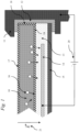
- Fig. 1 shows a cross-sectional view through a typical PV solar module.
- the front side of the module also known as the "sunny" side is at the top of the figure and the back side is at the bottom of the figure.
- the module is constructed as a stack of layers starting with the cover glass 10, encapsulating material 13, PV solar cell 14 and back-sheet 15.
- the edges of the module may be contained within a metal frame 11 adhered with a layer of silicone sealant, butyl rubber or composite tape 12.
- Encapsulating material or encapsulant 13 may include one or more layers of encapsulant as needed and as described herein as one layer, or two layers, or more.
- a high voltage 20 of up to 1500V DC may be maintained between the PV solar cell 14 and the frame 11. This creates a strong and constant electrical field 21 through the PV solar module.
- This constant electrical field provides a motive force for ions 16 within the cover glass to move towards the PV solar cell 14. It is believed that these ions are a prime cause of PID when they reach the PV solar cell 14 and interact with it.
- a coating 17 may be applied to the outside surface of the cover glass 10, or a coating 18 may be applied to the edge surface of the cover glass 10, or a coating 19 may be applied to the inside surface of the cover glass 10 or these coatings 17, 18 and 19 may be applied in any combination, for example just coating 17, or just coatings 17 and 19 or just coatings 18 and 19 etc.
- the coatings may be used to reduce or eliminate PID, it has been shown in studies that increased conductivity on the front surface of the cover glass 10 may contribute to PID.
- Typical clean dry glass has low conductivity, however the presence of water, especially contaminated with dirt, dust and dissolved or deposited salts may increase the conductivity on the surface of glass and/or reduce the surface resistivity of the glass. Therefore, a coating 17 for the outside cover glass surface that reduces the amount of dirt, dust or salt build-up on the surface or that prevents moisture from adhering to the surface could also be advantageous in reducing PID. Additionally the coating could be further advantageous if it exhibited a high surface resistivity when compared to low-iron soda-lime glass.
- a coating with hydrophobic, super-hydrophobic and or oleophobic properties could be used to provide such functionality.
- Hard, durable coatings with these properties can be made according to the methods of this disclosure by selecting silane precursors that incorporate organic R groups such as alkyl, phenyl, aliphatic saturated organic groups such as methyl, ethyl, propyl, butyl, pentyl, hexyl, cyclohexyl. These may also include aliphatically unsaturated organic groups such as vinyl, allyl, butenyl, pentenyl, hexenyl, and ethynyl, propynyl, butynyl.
- the organic R group may include an aromatic group.
- the aromatic group can be selected from among groups such as phenyl, benzyl, xylyl, styryl, naphthyl, 1-phenylethyl, tolyl, ethylbenzyl and 2-phenylethyl to create persistent hydrophobic coatings.
- Additives such as colloidal silica, carbon nanotubes, Buckminsterfullerene C 60 and C 70, could be used to engineer specific surface texture, which can further increase the hydrophobic property. In general the lower the surface energy of the coating, the more hydrophobic it is, and consequently it will also lower the surface resistivity of coated cover glass 10.
- Coatings with these properties can be made according to this disclosure by selection of silane precursors with small or no organic R groups and by addition of crosslinking within the material to increase density. This can be achieved by selecting precursors with high silanol functionalities. Density can further be increased by heat treatment at temperatures between about 100 °C to about 300 °C and between about 100 °C and about 500 °C and between about 100 °C and about 700 °C and under a commercial glass tempering process.
- Hard dense coatings may also act as a simple barrier to ion mobility.
- the barrier property of the coating can be increased by adding a function to capture or chelate alkali metal ions within the coating and prevent their further migration.
- the coating materials of the present disclosure may include ionic exchange resins such as polystyrene sulfonate, sulfonated polyphosphazene or other sulfonated polymers or chelating compounds such as thiol containing or quadridentatate schiff base ligands that have a strong affinity for ions and capture them in the coating or retard their mobility through the coating over the useful life of the PV solar module.
- the motive force for the ions is the electrical field developed between the grounded frame 11 and the PV solar cell 14.
- a potential difference up to 1500V DC 20 may exist between the PV solar cell 14 and ground.
- the outside surface of the cover glass 10 will be at a potential close to that of the frame and close to the ground potential. Therefore the electrical field 21 extends through the cover glass 10 to the PV solar cell 14.
- Alkali and alkaline-earth metal ions within the glass such as Na + , Mg ++ and Ca ++ are exposed to this field and over time can be moved through and out of the cover glass 10 and through the encapsulating material 13 or encapsulant to the PV solar cell 14 wherein they contribute to or cause PID.
- a coating 17, 18 and 19 applied to the cover glass 10, such that the electrical potential is close to equal on both outside and inside of the cover glass 10 would eliminate the electrical field 21 across the thickness of the cover glass 10.
- Such a coating could be made according to this disclosure by making the electrical resistivity of the coating low in comparison to the resistivity of the cover glass 10. The resistivity of the coating may be reduced by selection of precursor chemicals to include other non-alkali metal oxides in addition to or in replacement of silicon in the final coating.
- coatings with additives of SnO 2 , Al 2 O 3 , Si 3 N 4 , ZrO 2 , HfO 2 and Ce 2 O 3 , and similar act to increase the conductivity and reduce the resistivity of the coating to less than about 10 10 ⁇ / ⁇ sheet resistance.
- additives may be in the form of a fine powder, such as nanoparticles, added in small quantities.
- conductive carbon nanotubes (CNT) or silver nanowires could be dispersed in the liquid coating material to control the sheet resistance.
- RI refractive index
- n n 1 n 2
- the RI of the coating material 19 may be between about 1.52 and about 1.45 and between about 1.52 and about 1.48 and 1.52 ⁇ 0.02.
- the thickness of coating 19 may be between about 50 nm and about 10 ⁇ m, and between about 100 nm and about 250 nm, and between about 500 nm and about 5 ⁇ m, and between about 1 ⁇ m and about 10 ⁇ m.
- the RI of the coatings in the present disclosure may be tuned. Taking the base RI of a pure silica coating at about 1.45, then RI may be reduced by increasing the porosity of the material. Porosity may be increased by the selection of silane precursor chemicals that include organic groups which affect the way in which the silica network forms; coatings may be formed with nanoparticles either synthesized directly or added during formulation; porogen materials may be included that are burned off during a heat treatment step leaving behind pores in the formed coating. Suitable porogens include PEO, PPO, diethylene oxide, dipropylene oxide, PEG 100, 200, 300, 400, 600, Tween 20 and Tween 80.
- the RI of the coatings may be increased by the addition of metal oxide (e.g., ceramic) nanoparticles such as TiO 2 , SnO 2 , Al 2 O 3 , Si 3 N 4 , ZrO 2 , HfO 2 , Ce 2 O 3 and the like.
- metal oxide e.g., ceramic
- coatings 19 on the inside of the cover glass 10 is adhesion between the coating 19 and the cover glass 10 and between the coating 19 and the encapsulant material 13.
- Materials that may be included in the coating formulation that promote adhesion to the encapsulant materials include metharyloxypropyl-, glycidyloxypropyl- and methacrylamino propyl- trialkoxy silane.
- multiple steps may be used to apply the coating sol to a given substrate, such as for example, three steps.
- the substrate may be cleaned and pretreated.
- the substrate may be coated with the sol or mixture of sols.
- the final coating may be formed on the substrate.
- the substrate may be pretreated or pre-cleaned to remove surface impurities and to activate the surface by generating a fresh surface or new binding sites on the surface. It is desirable to increase the surface energy of the substrate through pretreatment or cleaning of the substrate surface to form an "activated" surface.
- an activated surface may be one with many exposed Si-OH moieties.
- An activated surface reduces the contact angle of the substrate and enables effective wetting of the sol on the surface.
- a combination of physical polishing or cleaning and/or chemical etching may be sufficient to provide even wetting of the sol.
- the substrate may be pretreated with a dilute surfactant solution (low molecular weight surfactants such as surfynol; long chain alcohols such as hexanol or octanol; low molecular weight ethylene oxide or propylene oxide; or a commercial dishwasher detergent such as CASCADE, FINISH, or ELECTRASOL to further help the sol spread better on the glass surface.
- a dilute surfactant solution low molecular weight surfactants such as surfynol; long chain alcohols such as hexanol or octanol; low molecular weight ethylene oxide or propylene oxide; or a commercial dishwasher detergent such as CASCADE, FINISH, or ELECTRASOL to further help the sol spread better on the glass surface.
- surface pretreatment may involve a combination of chemical and physical treatments of the surface.
- the chemical treatment steps may include (1) cleaning the surface with a solvent or combination of solvents, detergents, mild bases like sodium carbonate or ammonium carbonate and/or (2) cleaning the surface with a solvent along with an abrasive pad, (3) optionally chemically etching the surface, and/or (4) washing the surface with water.
- the physical treatment steps may include (1) cleaning the surface with a solvent or combination of solvents, (2) cleaning the surface with a solvent along with particulate abrasives, and (3) washing the surface with water. It should be appreciated that a substrate can be pretreated by using only the chemical treatment steps or only the physical treatment steps. Alternatively, both chemical and physical treatment steps could be used in any combination. It should be further appreciated that the physical cleaning action of friction between a cleaning brush or pad and the surface is an important aspect of the surface preparation.
- the surface may be treated with a solvent or combination of solvents with variable hydrophobicity.
- Typical solvents used are water, ethanol, isopropanol, acetone, and methyl ethyl ketone.
- a commercial glass cleaner e.g., WINDEX
- the surface may be treated with an individual solvent separately or by using a mixture of solvents.
- an abrasive pad e.g., SCOTCHBRITE
- the surface may be washed or rinsed with water and dried.
- substrate preparation by this method involves cleaning the surface with an organic solvent such as ethanol, isopropanol, or acetone to remove organic surface impurities, dirt, dust, and/or grease (with or without an abrasive pad) followed by cleaning the surface with water.
- an organic solvent such as ethanol, isopropanol, or acetone
- Another example involves cleaning the surface with methyl ethyl ketone (with or without an abrasive pad) followed by washing the surface with water.
- Another example is based on using a 1:1 mixture of ethanol and acetone to remove organic impurities followed by washing the surface with water.
- an additional, optional step of chemically treating the surface with concentrated nitric acid, sulfuric acid, or piranha solution may be done to make the surface suitable for bonding to the deposited sol. Typically this step would be performed prior to the last step of rinsing the surface with water.
- the substrate may be placed in piranha solution for 20 minutes followed by soaking in deionized water for 5 minutes. The substrate may then be transferred to another container holding fresh deionized water and soaked for another 5 minutes. Finally, the substrate may be rinsed with deionized water and air-dried.
- the substrate may be alternatively or additionally prepared by physical treatment.
- the surface may be simply cleaned with a solvent and the mechanical action of a cleaning brush or pad, optionally a surfactant or detergent can be added to the solvent, after which the substrate is rinsed with water and air dried.
- the surface may be first cleaned with water followed by addition of powdered abrasive particles such as ceria, titania, zirconia, alumina, aluminum silicate, silica, magnesium hydroxide, aluminum hydroxide particles, silicon nitride, silicon carbide, or combinations thereof onto the surface of the substrate to form a slurry or paste on the surface.
- the abrasive media can be in the form a powder or it can be in the form of slurry, dispersion, suspension, emulsion, or paste.
- the particle size of the abrasives can vary from 0.1 to 10 microns and in some embodiments from 1 to 5 microns.
- the substrate may be polished with the abrasive slurry via rubbing with a pad (e.g., a SCOTCHBRITE pad), a cloth, a foam, or paper pad.
- a pad e.g., a SCOTCHBRITE pad
- the substrate may be polished by placement on the rotating disc of a polisher followed by application of abrasive slurry on the surface and rubbing with a pad as the substrate rotates on the disc.
- Another alternative method involves use of an electric polisher that can be used as a rubbing pad in combination with abrasive slurry to polish the surface.
- the substrates polished with the slurry may be cleaned by water and air-
- the coating may be deposited on a substrate by techniques known in the art, including dip coating, spray coating, flow coating, roll coating or slot-die coating to form a uniform coating on the substrate.
- Other methods for deposition that can be used include spin-coating; aerosol deposition; ultrasound, heat, or electrical deposition means; micro-deposition techniques such as ink-jet, spay-jet, xerography; or commercial printing techniques such as silk printing, dot matrix printing, etc.
- Deposition of the sol may be done under ambient conditions or under controlled temperature and humidity conditions. In some embodiments the temperature is controlled between 20 °C and 35 °C and/or the relative humidity is controlled between 20% and 60% or more preferably between 25% and 35%.
- the sol may be deposited by flow coating wherein the sol is dispensed from a single nozzle onto a moving substrate at a rate such that the flowing sol leads to a uniform deposition onto a surface or from multiple nozzles onto a stationary surface or from a slot onto a stationary surface.
- Another method of deposition is via depositing the liquid sol onto a substrate followed by use of a mechanical dispersant to spread the liquid evenly onto a substrate.
- a squeegee or other mechanical device having a sharp, well-defined, uniform edge may be used to spread the sol such as roll coating.
- the thickness of the coating mixture as deposited may be affected by the coating method, as well as by the viscosity of the coating mixture. Accordingly, the coating method should be selected so that the desired coating thickness is achieved for any given coating mixture.
- the critical parameter for controlling average thickness may be the non-volatile solids content of the coating material.
- the critical parameters may be the non-volatile solids content of the coating material, the speed of the substrate being coated and the speed and pressure of the rollers.
- the non-volatile solids content of the coating material may be between about 0.5 wt% and about 10 wt%, and between about 0.8 wt% and about 5 wt%, and between about 1.4 wt% and about 3 wt%.
- the speed of the substrate may be between about 2 m/minute and about 12 m/minute, and between about 3 m/minute and about 8 m/minute.
- the speed of the application roller can be considered as a ratio to the substrate speed such that a substrate::roller ratio of about 0.1 to about 2.00, and about 0.75 to about 1.25 may be maintained.
- the offset between the doctor roller and the application roller may be between about -0.05 mm and about -0.5 mm and the offset between the scraper roller and the application roller may be between about 0 mm and about -0.5 mm.
- the offset between the application roller and the substrate surface may be between about -0.01 mm and -0.50 mm.
- the hardness of the application roller is between about 25 Shore and about 50 Shore and between about 30 Shore and 40 Shore, all measured on the Shore A scale.
- the coating may be dried and cured and/or aged to form the final coating.
- the coating may be dried and cured under ambient or room temperature conditions.
- the coating may be dried by a flash-off oven either by blowing hot air across the surface or by the application of infrared heat.
- the substrate surface may be heated to a temperature of between about 100 °C and about 300 °C and between about 150 °C and about 250 °C for a time of between about 20 seconds and 10 minutes and between about 1 minute and 5 minutes.
- the coating may be cured by heating in an oven at a temperature of between about 100 °C and about 500 °C and between about 120 °C and about 300 °C and between about 200 °C and 300 °C for a dwell time of between about 5 minutes and about 60 minutes and between about 15 minutes and 30 minutes.
- lower cure temperatures require longer cure times.
- Maximum cure temperature may be determined by the desired coating hardness, higher temperatures will generate harder coatings and by limitations imposed by the substrate such as not affecting the temper of the glass substrate.
- the coating may be cured during a standard glass tempering process.
- Example 1 Sol I was prepared by charging a 500 mL flask with 177 g of IPA and 25 g of 0.04 M HCl. After stirring at 100 rpm at room temperature for about 1 minute, 2.87 g (0.021 moles) of methyltrimethoxysilane was added to the mixture. The mixture was stirred at room temperature for about 30 minutes. Sol II was prepared by charging a 500 mL flask with 177 g of IPA and 25 g of 0.04 M HCl. After stirring at 100 rpm at room temperature for about 1 minute, 3.71 g (0.021 moles) of (3,3,3-trifluoropropyl)-trimethoxysilane was added to the mixture.
- Example 2 Sol I was prepared by charging a 500 mL flask with 177 g of IPA and 25 g of 0.04 M HCl. After stirring at 100 rpm at room temperature for about 1 minute, 2.87 g (0.021 moles) of methyltrimethoxysilane was added to the mixture. The mixture was stirred at room temperature for about 30 minutes. Sol II was prepared by charging a 500 mL flask with 177 g of IPA and 25 g of 0.04 M HCl. After stirring at 100 rpm at room temperature for about 1 minute, 3.71 g (0.021moles) of (3,3,3-trifluoropropyl)-trimethoxysilane was added to the mixture.
- sol was prepared by charging a 500 mL flask with 354 g of IPA and 50 g of 0.04 M HCl. After stirring at 100 rpm room temperature for about 1 minute, 4.37 g (0.0321 moles) of methyltrimethoxysilane was added to the mixture. The mixture was stirred at room temperature for about 30 minutes followed by addition of 7.08 g (0.034 moles) of tetraethoxysilane. The final mixture was stirred at room temperature for about 30 minutes. This mixture was allowed to age under ambient conditions for 48 hours.
- Example 4 Sol I was prepared by charging a 500 mL flask with 177 g of IPA and 25 g of 0.04 M HCl. After stirring at 100 rpm at room temperature for about 1 minute, 2.63g (0.0193 moles) of methyltrimethoxysilane was added to the mixture. The mixture was stirred at room temperature for about 30 minutes. Sol II was prepared by charging a 500 mL flask with 177 g of IPA and 25 g of 0.04 M HCl. After stirring at 100 rpm at room temperature for about 1 minute, 0.284 g (0.0013 moles) of (3,3,3-trifluoropropyl)-trimethoxysilane was added to the mixture.
- Example 5 Sol I was prepared by charging a 500 mL flask with 177 g of IPA and 25 g of 0.04 M HCl. After stirring at 100 rpm at room temperature for about 1 minute, 2.39g (0.01753moles) of methyltrimethoxysilane was added to the mixture. The mixture was stirred at room temperature for about 30 minutes. Sol II was prepared by charging a 500 mL flask with 177 g of IPA and 25 g of 0.04 M HCl. After stirring at 100 rpm at room temperature for about 1 minute, 0.399 g (0.00262 moles) of (3,3,3-trifluoropropyl)-trimethoxysilane was added to the mixture.
- sol was prepared by charging a 500 mL flask with 345 g of IPA and 50 g of 0.08 M HCl. After stirring at 100 rpm at room temperature for about 1 minute, 9.13 g (0.067 moles) of methyltrimethoxysilane was added to the mixture. The mixture was stirred at room temperature for about 30 minutes followed by addition of 13.96 g (0.067 moles) of tetraethoxysilane. The final mixture was stirred at room temperature for about 30 minutes. This mixture was allowed to age under ambient conditions for 48 hours. 10.5 mL of 1-methoxy-2-propanol was added to the sol mixture and stirred for about 1 minute.
- sol was prepared by charging a 500 mL flask with 197 g of IPA and 140 g of 0.08 M HCl. After stirring at 100 rpm at room temperature for about 1 minute, 30.2 g (0.288) of methyltrimethoxysilane was added to the mixture. The mixture was stirred at room temperature for about 30 minutes followed by addition of 60 g (0.288 moles) of tetraethoxysilane. The final mixture was stirred at room temperature for about 30 minutes. This mixture was allowed to age under ambient conditions for 48 hours.
- Fig 2 shows experimental results demonstrating the enhanced PID resistance of a hydrophobic anti-reflection coating relative to a hydrophilic anti-reflection coating and no coating on the front-side of PV solar module cover glass.
- coating material made according to Example 3 was used to roll-coat the front-side of two 30 cm x 30 cm pieces of standard patterned low-iron soda-lime cover glass characteristic of glass used in the manufacture of crystalline silicon PV solar modules.
- the coating thickness was about 110 nm.
- the coating was cured at about 275 °C for 30 minutes. These samples were referred to as "Hydrophobic ARC".
- Two more 30 cm x 30 cm pieces of the same glass were selected and labeled "Uncoated.”
- Two 30 cm x 30 cm pieces of a similar glass with a commercially available anti-reflection coating and with a water contact angle measured at ⁇ 10° were labeled "Hydrophilic ARC".
- the six pieces of cover glass were assembled into single-cell mini-modules using standard commercially available EVA encapsulant and backsheet material. Specially prepared PID-prone 156mm multi-crystalline silicon PV cells were used. The cells were positioned within the mini-module such that their top-left corner was spaced a distance of about 2.5 cm from the top-left corner of the cover glass. A strip of adhesive copper tape was affixed along the top edge of the cover glass.
- the six mini-modules were flash tested to measure their initial maximum power (P MAX ). They were then biased with a voltage of 1000 Vdc between the cell and the copper tape and placed into a temperature and humidity chamber under conditions of 85 °C and 85% RH. The mini-modules were removed and flash tested and P MAX was recorded at 24-hour, 48-hour, 72-hour and 96-hour read-points.
- Fig 3 shows experimental results demonstrating enhanced PID resistance of coatings on the back-side of the PV solar module cover glass relative to no coatings and just coatings on the front-side of the PV solar module cover glass.
- coating material made according to Example 3 was used to roll-coat six 20 cm x 20 cm pieces of standard patterned low-iron soda-lime cover glass characteristic of glass used in the manufacture of crystalline silicon PV solar modules. The coating thickness was about 110 nm. The coating was cured at about 275 °C for 30 minutes. Of the six pieces, two were coated on the front-side (that is the side that typically faces the sun in a PV solar module); two were coated on the back-side and two were coated on both the front and back sides.
- the results of the experiment shows a very distinct enhancement of PID resistance for the mini-modules with coatings on the back-side and on both sides relative to mini-modules with no coating or with just a coating on the front-side.
- the mini-modules with coatings on both sides and just on the back-side behaved in a similar manner, retaining about 50% of their initial power after the full 96 hours of stress.
- the mini-module with just a front-side coating performed better than the uncoated mini-module, retaining about 30% of its initial power after 24 hours of stress whereas the uncoated mini-module had degraded to close to zero power at the same read-point.
- This experiment was conducted with an aluminum foil sheet completely covering the front-side of the cover glass. It is possible that the surface resistivity advantage of the hydrophobic coating over uncoated glass was masked by the low electrical resistance foil.
- Coatings on glass to reduce the effects of PID as described herein may be employed to relax design and specification constraints on other components contained within the PV module to create a better cost and performance optimized module. For example, by providing an effective ion barrier, coated glass may allow the use of silicon nitride cell coatings with relaxed process requirements.
- embodiments with coatings on the interior and/or exterior surfaces of the glass back-sheet may be used to reduce the effects of PID in a manner that is analogous to those previously described for coating the front cover glass.
- References to coating on the inside or outside or interior or exterior have equal meaning regardless of whether the glass is on the front cover (sun facing) side of the PV module or on the backside and used as a back-sheet.
- References to the front of the cover glass are analogous to the back of the back-sheet and references to the back of the cover glass are analogous to the front of the back-glass.
- Embodiments described herein are well suited to performing various other steps or variations of the steps recited herein, and in a sequence other than that depicted and/or described herein.
Landscapes
- Chemical & Material Sciences (AREA)
- Life Sciences & Earth Sciences (AREA)
- Engineering & Computer Science (AREA)
- Materials Engineering (AREA)
- Organic Chemistry (AREA)
- Wood Science & Technology (AREA)
- Chemical Kinetics & Catalysis (AREA)
- Geochemistry & Mineralogy (AREA)
- General Chemical & Material Sciences (AREA)
- Inorganic Chemistry (AREA)
- Physics & Mathematics (AREA)
- General Physics & Mathematics (AREA)
- Optics & Photonics (AREA)
- Paints Or Removers (AREA)
- Surface Treatment Of Glass (AREA)
- Photovoltaic Devices (AREA)
Claims (14)
- Gegenüber potenzialinduzierter Degradation (PID) beständiges photovoltaisches Solarmodul, umfassend:ein vorderes Abdeckglas (10) mit einer Beschichtung (17, 18, 19);wobei die Beschichtung beinhaltet: ein Nanopartikeladditiv, umfassend ein Metalloxid, -nitrid oder -carbid; mindestens eine/n von leitfähigen Kohlenstoffnanoröhren (CNT) oder Silbernanodrähten, dispergiert in der Beschichtung; oder ein Nanopartikeladditiv, ausgewählt aus der Gruppe, die aus SnO2, Al2O3, Si3N4, ZrO2, HfO2 und Ce2O3 besteht;mindestens eine photovoltaische Solarzelle (14) mit mindestens einer Schicht Verkapselungsstoff (13), angeordnet auf einer Oberfläche der photovoltaischen Solarzelle; undeine Rückwand (15),wobei das vordere Abdeckglas mit der Beschichtung eine Antireflexeigenschaft, eine hydrophobe Eigenschaft und eine verstärkte Ionenmigrationsblockierungseigenschaft, verglichen mit dem gleichen vorderen Abdeckglas ohne die Beschichtung, aufweist; undwobei das vordere Abdeckglas (10) auf mindestens einer Vorderseite oder einer Rückseite beschichtet ist; wobei ein Flächenwiderstand der Beschichtung des vorderen Abdeckglases geringer als 1010 Ω/sq ist, unddie Beschichtung (17, 18, 19) eine Kombination von Solen mit folgender Formel umfasst:
[RSi(OH)2O0,5]a[RSi01,5]b[RSi(OH)O]c[R'Si(OH)2O0.5]m[R'SiO1,5]n[R'Si(OH)O ]p[SiO2]w[Si(OH)O1,5]x[Si(OH)2O]y[Si(OH)3O0.5]z
wobei R unabhängig Methyl oder optional eine substituierte oder unsubstituierte C2- bis C10-Alkylgruppe, eine substituierte oder unsubstituierte C3- bis C20-Cycloalkylgruppe, eine substituierte oder unsubstituierte C1- bis C10-Hydroxyalkylgruppe, eine substituierte oder unsubstituierte C6- bis C20-Arylgruppe, eine substituierte oder unsubstituierte C2- bis C20-Heteroarylgruppe, eine substituierte oder unsubstituierte C2- bis C10-Alkenylgruppe, eine substituierte oder unsubstituierte Carboxylgruppe, eine substituierte oder unsubstituierte (Meth)acrylgruppe, eine substituierte oder unsubstituierte Glycidylethergruppe oder eine Kombination davon ist;wobei R' eine fluorsubstituierte C3-Alkylgruppe oder optional eine C4- bis C10-Alkylgruppe, eine fluorsubstituierte C3- bis C20-Cycloalkylgruppe, eine fluorsubstituierte C1- bis C10-Hydroxyalkylgruppe, eine fluorsubstituierte Arylgruppe, eine fluorsubstituierte C2- bis C20-Heteroarylgruppe, eine fluorsubstituierte C2- bis C10-Alkenylgruppe, eine fluorsubstituierte Carboxylgruppe, eine fluorsubstituierte (Meth)acrylgruppe, eine fluorsubstituierte Glycidylethergruppe oder eine Kombination davon ist; und
- Solarmodul nach Anspruch 1, wobei vorderseitige Beschichtung (17) des vorderen Abdeckglases (10) einen Brechungsindex und eine Dicke aufweist, die aus der Gruppe ausgewählt sind, die besteht aus: i. dem Brechungsindex zwischen 1,52 und 1,25 und der Dicke zwischen 50 nm und 250 nm; und ii. dem Brechungsindex zwischen 1,52 und 1,45 und der Dicke zwischen 50 nm und 10 µm.
- Solarmodul nach Anspruch 1, wobei mindestens die Vorder- und Rückseite des vorderen Abdeckglases (10) beschichtet sind und alle beschichteten Oberflächen elektrisch verbunden sind.
- Solarmodul nach Anspruch 1, wobei ein Flächenwiderstand der Beschichtung (17, 18, 19) des vorderen Abdeckglases niedriger als der Flächenwiderstand des äquivalenten vorderen Abdeckglases ist, das unbeschichtet ist.
- Solarmodul nach Anspruch 1, wobei die Beschichtung (17, 18, 19) des vorderen Abdeckglases ferner eine oleophobe Eigenschaft aufweist.
- Solarmodul nach Anspruch 1, wobei die Beschichtung (17, 18, 19) aus mindestens zwei Solen hergestellt ist und wobei die mindestens zwei Sole vor dem Herstellen der Beschichtung separat hydrolysiert werden.
- Solarmodul nach Anspruch 1, wobei das vordere Abdeckglas (10) ein vorbehandeltes vorderes Abdeckglas ist, bevor die Beschichtung (17, 18, 19) aufgebracht wird.
- Solarmodul nach Anspruch 7, wobei das vorbehandelte vordere Abdeckglas (10) durch eine physikalische Vorbehandlung oder eine chemische Vorbehandlung vorbehandelt wird, bevor die Beschichtung (17, 18, 19) aufgebracht wird.
- Solarmodul nach Anspruch 3, wobei die vorderseitige Beschichtung (17) des vorderen Abdeckglases (10) einen Brechungsindex und eine Dicke aufweist, die aus der Gruppe ausgewählt sind, die besteht aus: i. dem Brechungsindex zwischen 1,52 und 1,25 und der Dicke zwischen 50 nm and 250 nm; und ii. dem Brechungsindex zwischen 1,52 und 1,45 und der Dicke zwischen 50 nm and 10 µm; und
- Solarmodul nach Anspruch 3, wobei die Beschichtung (17, 18, 19) aus mindestens zwei Solen hergestellt ist und wobei die mindestens zwei Sole vor dem Herstellen der Beschichtung separat hydrolysiert werden.
- Solarmodul nach Anspruch 1, wobei mindestens eine Schicht des Verkapselungsstoffs zwei Schichten Verkapselungsstoff umfasst.
- Solarmodul nach Anspruch 1, wobei die Beschichtung ein Nanopartikeladditiv umfasst, das ausgewählt ist aus der Gruppe, die aus SnO2, Al2O3, Si3N4, ZrO2, HfO2 und Ce2O3 besteht.
- Solarmodul nach Anspruch 1, wobei die Beschichtung mindestens eine/n von leitfähigen Kohlenstoffnanoröhren (CNT) oder Silbernanodrähten, dispergiert in der Beschichtung, umfasst.
- Solarmodul nach Anspruch 1, wobei die Beschichtung ein Nanopartikeladditiv, umfassend ein Metalloxid, -nitrid oder -carbid, umfasst.
Applications Claiming Priority (3)
| Application Number | Priority Date | Filing Date | Title |
|---|---|---|---|
| US201462024440P | 2014-07-14 | 2014-07-14 | |
| US14/491,259 US9382449B2 (en) | 2014-09-19 | 2014-09-19 | Optical enhancing durable anti-reflective coating |
| PCT/US2015/040393 WO2016011041A1 (en) | 2014-07-14 | 2015-07-14 | Coating materials and methods for enhanced reliability |
Publications (4)
| Publication Number | Publication Date |
|---|---|
| EP3170208A1 EP3170208A1 (de) | 2017-05-24 |
| EP3170208A4 EP3170208A4 (de) | 2018-04-18 |
| EP3170208B1 true EP3170208B1 (de) | 2024-06-05 |
| EP3170208C0 EP3170208C0 (de) | 2024-06-05 |
Family
ID=55078989
Family Applications (2)
| Application Number | Title | Priority Date | Filing Date |
|---|---|---|---|
| EP15821993.1A Active EP3170208B1 (de) | 2014-07-14 | 2015-07-14 | Beschichtungsmaterialien und verfahren für verbesserte zuverlässigkeit |
| EP15822675.3A Active EP3172260B1 (de) | 2014-07-14 | 2015-07-14 | Beständige antireflektierende beschichtung mit hoher verstärkung |
Family Applications After (1)
| Application Number | Title | Priority Date | Filing Date |
|---|---|---|---|
| EP15822675.3A Active EP3172260B1 (de) | 2014-07-14 | 2015-07-14 | Beständige antireflektierende beschichtung mit hoher verstärkung |
Country Status (3)
| Country | Link |
|---|---|
| EP (2) | EP3170208B1 (de) |
| CN (2) | CN107075304B (de) |
| WO (1) | WO2016011041A1 (de) |
Families Citing this family (34)
| Publication number | Priority date | Publication date | Assignee | Title |
|---|---|---|---|---|
| US9376593B2 (en) | 2009-04-30 | 2016-06-28 | Enki Technology, Inc. | Multi-layer coatings |
| US9353268B2 (en) | 2009-04-30 | 2016-05-31 | Enki Technology, Inc. | Anti-reflective and anti-soiling coatings for self-cleaning properties |
| US9382449B2 (en) | 2014-09-19 | 2016-07-05 | Enki Technology, Inc. | Optical enhancing durable anti-reflective coating |
| US9376589B2 (en) | 2014-07-14 | 2016-06-28 | Enki Technology, Inc. | High gain durable anti-reflective coating with oblate voids |
| US9598586B2 (en) | 2014-07-14 | 2017-03-21 | Enki Technology, Inc. | Coating materials and methods for enhanced reliability |
| EP3185309A1 (de) * | 2015-12-23 | 2017-06-28 | Amcor Flexibles Transpac | Wärmereflektierendes solarmodul |
| KR102634160B1 (ko) | 2017-11-30 | 2024-02-06 | 악살타 코팅 시스템즈 게엠베하 | 고 전달 효율 어플리케이터를 활용하는 코팅 조성물의 적용을 위한 시스템, 코팅 층 및 상응하는 방법 |
| US12539525B2 (en) | 2017-11-30 | 2026-02-03 | Axalta Coating Systems Ip Co., Llc | Coating compositions for application utilizing a high transfer efficiency applicator and methods and systems thereof |
| CN108388041B (zh) * | 2018-02-08 | 2021-06-01 | Tcl华星光电技术有限公司 | 彩膜基板及其制造方法、遮光材料及遮光层的制造方法 |
| TWI676294B (zh) * | 2018-05-14 | 2019-11-01 | 致達應材股份有限公司 | 太陽能發電模組與其製程 |
| CN108659694B (zh) * | 2018-06-15 | 2020-10-23 | 惠州学院 | 一种聚氨酯木器漆 |
| CN108715950B (zh) * | 2018-07-04 | 2019-11-26 | 郑州大学第一附属医院 | 一种具有骨诱导活性的骨固定器件用钛合金 |
| JP7472794B2 (ja) * | 2018-11-13 | 2024-04-23 | Agc株式会社 | 撥水撥油層付き基材、蒸着材料および撥水撥油層付き基材の製造方法 |
| KR102799381B1 (ko) * | 2018-11-13 | 2025-04-22 | 에이지씨 가부시키가이샤 | 발수발유층 형성 기재, 증착 재료 및 발수발유층 형성 기재의 제조 방법 |
| US10615745B1 (en) | 2019-01-09 | 2020-04-07 | Kuwait Institute For Scientific Research | Device and method for measuring effect of soiling on photovoltaic device |
| US11254838B2 (en) | 2019-03-29 | 2022-02-22 | Ppg Industries Ohio, Inc. | Single component hydrophobic coating |
| CN110002767B (zh) * | 2019-04-28 | 2021-10-08 | 邦弗特新材料股份有限公司 | 一种用于光伏玻璃的高透光率疏水涂膜的制备方法 |
| CN109987857B (zh) * | 2019-04-29 | 2021-11-23 | 布勒莱宝光学设备(北京)有限公司 | 新型低辐射节能膜系及其制备方法和应用 |
| CN110444613B (zh) * | 2019-08-14 | 2020-12-29 | 明冠新材料股份有限公司 | 一种高阻水hjt光伏电池 |
| CN111019522A (zh) * | 2019-12-20 | 2020-04-17 | 苏州浩纳新材料科技有限公司 | 具有自清洁和增透双功能的太阳能组件涂层及制备方法 |
| CN111653641A (zh) * | 2020-05-09 | 2020-09-11 | 晶澳(扬州)太阳能科技有限公司 | 一种薄膜的生成方法 |
| US12122932B2 (en) | 2020-05-29 | 2024-10-22 | Axalta Coating Systems Ip Co., Llc | Coating compositions for application utilizing a high transfer efficiency applicator and methods and systems thereof |
| CN113930748B (zh) * | 2020-07-13 | 2024-02-20 | 苏州阿特斯阳光电力科技有限公司 | 太阳能电池的制备方法、太阳能电池与光伏组件 |
| CN112038421B (zh) * | 2020-08-19 | 2022-04-05 | 上海纳米技术及应用国家工程研究中心有限公司 | 一种光诱导太阳能电池表面自清洁涂层的制备方法 |
| CN112366251A (zh) * | 2020-11-25 | 2021-02-12 | 河南安彩高科股份有限公司 | 一种太阳能电池减反射膜的制备方法 |
| CN112745702A (zh) * | 2020-12-24 | 2021-05-04 | 上大新材料(泰州)研究院有限公司 | 一种增强透明疏水涂层及其制备方法 |
| CN113025087B (zh) * | 2021-03-04 | 2022-06-10 | 东莞南玻太阳能玻璃有限公司 | 一种硅溶胶掺杂的防眩光增透镀膜溶液、制备方法及应用 |
| CN113793875A (zh) * | 2021-09-13 | 2021-12-14 | 西安隆基绿能建筑科技有限公司 | 一种光伏封装板及其制作方法、光伏组件 |
| CN115340790A (zh) * | 2022-07-01 | 2022-11-15 | 杭州福斯特应用材料股份有限公司 | 一种涂层组合物、封装材料及光伏组件 |
| CN115368679A (zh) * | 2022-09-14 | 2022-11-22 | 中海石油(中国)有限公司 | 一种具有阻燃特性的密封橡胶材料及其制备方法 |
| CN118652542B (zh) * | 2024-06-27 | 2025-08-26 | 会通特种材料科技有限公司 | 一种瞬时亲水长碳链聚酰胺粉末材料及其制备方法 |
| CN119708428B (zh) * | 2024-12-23 | 2025-07-25 | 南昌航空大学 | 一种具有优异光固化和光响应性能的可回收再利用自修复聚氨酯有机硅树脂及其制备方法 |
| CN119955336B (zh) * | 2025-02-14 | 2026-03-06 | 扬州大学 | 一种耐腐蚀自清洁光反射陶瓷涂层及其制备方法 |
| CN121063831A (zh) * | 2025-08-28 | 2025-12-05 | 东莞市捷润电子科技有限公司 | 一种显示屏用耐磨抗指纹玻璃盖板及其制备工艺 |
Family Cites Families (14)
| Publication number | Priority date | Publication date | Assignee | Title |
|---|---|---|---|---|
| JPH09115334A (ja) * | 1995-10-23 | 1997-05-02 | Mitsubishi Materiais Corp | 透明導電膜および膜形成用組成物 |
| US20090151773A1 (en) * | 2007-12-14 | 2009-06-18 | E. I. Du Pont De Nemours And Company | Acid Terpolymer Films or Sheets and Articles Comprising the Same |
| US20090169870A1 (en) * | 2007-12-27 | 2009-07-02 | Essilor International (Compagnie Generale D'optique) | Carbon Nanotube-Based Curable Coating Composition Providing Antistatic Abrasion-Resistant Coated Articles |
| WO2009111122A2 (en) * | 2008-03-04 | 2009-09-11 | Dow Corning Corporation | Silsesquioxane resins |
| US8864897B2 (en) * | 2009-04-30 | 2014-10-21 | Enki Technology, Inc. | Anti-reflective and anti-soiling coatings with self-cleaning properties |
| US8557877B2 (en) * | 2009-06-10 | 2013-10-15 | Honeywell International Inc. | Anti-reflective coatings for optically transparent substrates |
| CN103154320B (zh) * | 2010-10-06 | 2015-12-16 | 3M创新有限公司 | 具有纳米二氧化硅基涂层的抗反射制品 |
| TW201251069A (en) * | 2011-05-09 | 2012-12-16 | 3M Innovative Properties Co | Photovoltaic module |
| JP2013080067A (ja) * | 2011-10-03 | 2013-05-02 | Sketch:Kk | 塗布液及び基板 |
| US9109121B2 (en) * | 2011-10-13 | 2015-08-18 | Intermolecular, Inc. | Sol-gel based antireflective coatings using alkyltrialkoxysilane binders having low refractive index and high durability |
| US9082914B2 (en) * | 2012-01-13 | 2015-07-14 | Gaurdian Industries Corp. | Photovoltaic module including high contact angle coating on one or more outer surfaces thereof, and/or methods of making the same |
| US8883252B2 (en) * | 2012-06-28 | 2014-11-11 | Intermolecular, Inc. | Antireflective coatings with self-cleaning, moisture resistance and antimicrobial properties |
| US9831361B2 (en) * | 2012-12-14 | 2017-11-28 | Robert Bosch Gmbh | Method of fabricating nanocone texture on glass and transparent conductors |
| CN103254802B (zh) * | 2013-03-19 | 2015-06-03 | 江苏鹿山光伏科技有限公司 | 一种抗光伏组件潜在电势诱导衰减的eva封装胶膜 |
-
2015
- 2015-07-14 EP EP15821993.1A patent/EP3170208B1/de active Active
- 2015-07-14 CN CN201580049074.7A patent/CN107075304B/zh active Active
- 2015-07-14 CN CN201580049073.2A patent/CN107078172B/zh active Active
- 2015-07-14 WO PCT/US2015/040393 patent/WO2016011041A1/en not_active Ceased
- 2015-07-14 EP EP15822675.3A patent/EP3172260B1/de active Active
Also Published As
| Publication number | Publication date |
|---|---|
| CN107075304B (zh) | 2020-10-16 |
| CN107078172B (zh) | 2020-06-30 |
| EP3170208A4 (de) | 2018-04-18 |
| EP3172260B1 (de) | 2022-01-26 |
| EP3172260A4 (de) | 2018-08-08 |
| EP3170208A1 (de) | 2017-05-24 |
| EP3170208C0 (de) | 2024-06-05 |
| WO2016011041A1 (en) | 2016-01-21 |
| CN107075304A (zh) | 2017-08-18 |
| CN107078172A (zh) | 2017-08-18 |
| EP3172260A2 (de) | 2017-05-31 |
Similar Documents
| Publication | Publication Date | Title |
|---|---|---|
| EP3170208B1 (de) | Beschichtungsmaterialien und verfahren für verbesserte zuverlässigkeit | |
| US9598586B2 (en) | Coating materials and methods for enhanced reliability | |
| KR102610317B1 (ko) | 신규한 카보실록산 중합체 조성물, 그 제조 방법 및 용도 | |
| EP2656119B1 (de) | Glasartige antireflektierende, mit kieselsäurenanopartikeln beschichtete polymerfolien, verfahren zur herstellung und lichtabsorbierende vorrichtungen damit | |
| US20140261673A1 (en) | Tuning the anti-reflective, abrasion resistance, anti-soiling and self-cleaning properties of transparent coatings for different glass substrates and solar cells | |
| JP6092217B2 (ja) | 背面に疎水性コーティングを有する薄膜太陽電池モジュール、その製造方法、その使用および疎水性コーティングの使用 | |
| WO2007026927A1 (ja) | 光電変換装置及びその製造方法並びに光発電装置 | |
| JP2011071523A (ja) | ソーラーセル | |
| WO2008136894A2 (en) | Method of making a photovoltaic device with scratch-resistant antireflective coating mid resulting product | |
| CN102308231A (zh) | 光学涂层 | |
| WO2016011071A2 (en) | High gain durable anti-reflective coating | |
| CN105408434B (zh) | 水性防污镀剂、防污镀层、层叠体以及太阳电池模块 | |
| KR101774051B1 (ko) | 보호 필름 및 태양 전지용 프론트 시트 | |
| US20130061905A1 (en) | Photovoltaic Devices Comprising an Anti-Reflective Layer Containing Dispersed Objects Having Areas with Different Refractive Indices | |
| US20120045867A1 (en) | Anti-reflective photovoltaic module | |
| JPWO2009051122A1 (ja) | 薄膜太陽電池モジュール | |
| JP6805127B2 (ja) | コーティング膜付きガラス板及びその製造方法 | |
| KR101326140B1 (ko) | 기판에 텍스처가 형성된 2중 텍스처 구조의 칼코게나이드계 태양전지의 제조방법 및 이에 따라 제조된 칼코게나이드계 태양전지 | |
| CN112147722A (zh) | 一种光伏玻璃用的增透膜及其制备方法和应用 | |
| JP2003092417A (ja) | 光電変換素子 | |
| CN117363061B (zh) | 一种用于防月尘黏附的超疏水导电复合涂层及其制备方法 | |
| JP4637474B2 (ja) | 色素増感型太陽電池 | |
| CN106655995B (zh) | 自洁式光电转换太阳能瓦 | |
| KR102911498B1 (ko) | 유전체 코팅 | |
| CN119955158A (zh) | 一种抗原子氧/高太阳吸收比/高发射的柔性薄膜及其制备方法与应用 |
Legal Events
| Date | Code | Title | Description |
|---|---|---|---|
| STAA | Information on the status of an ep patent application or granted ep patent |
Free format text: STATUS: THE INTERNATIONAL PUBLICATION HAS BEEN MADE |
|
| PUAI | Public reference made under article 153(3) epc to a published international application that has entered the european phase |
Free format text: ORIGINAL CODE: 0009012 |
|
| STAA | Information on the status of an ep patent application or granted ep patent |
Free format text: STATUS: REQUEST FOR EXAMINATION WAS MADE |
|
| 17P | Request for examination filed |
Effective date: 20170113 |
|
| AK | Designated contracting states |
Kind code of ref document: A1 Designated state(s): AL AT BE BG CH CY CZ DE DK EE ES FI FR GB GR HR HU IE IS IT LI LT LU LV MC MK MT NL NO PL PT RO RS SE SI SK SM TR |
|
| AX | Request for extension of the european patent |
Extension state: BA ME |
|
| DAV | Request for validation of the european patent (deleted) | ||
| DAX | Request for extension of the european patent (deleted) | ||
| A4 | Supplementary search report drawn up and despatched |
Effective date: 20180321 |
|
| RIC1 | Information provided on ipc code assigned before grant |
Ipc: H01L 31/042 20140101ALI20180315BHEP Ipc: H01L 31/18 20060101ALI20180315BHEP Ipc: H01L 31/0216 20140101AFI20180315BHEP |
|
| RAP1 | Party data changed (applicant data changed or rights of an application transferred) |
Owner name: FIRST SOLAR, INC |
|
| STAA | Information on the status of an ep patent application or granted ep patent |
Free format text: STATUS: EXAMINATION IS IN PROGRESS |
|
| 17Q | First examination report despatched |
Effective date: 20210729 |
|
| GRAP | Despatch of communication of intention to grant a patent |
Free format text: ORIGINAL CODE: EPIDOSNIGR1 |
|
| STAA | Information on the status of an ep patent application or granted ep patent |
Free format text: STATUS: GRANT OF PATENT IS INTENDED |
|
| INTG | Intention to grant announced |
Effective date: 20230926 |
|
| GRAJ | Information related to disapproval of communication of intention to grant by the applicant or resumption of examination proceedings by the epo deleted |
Free format text: ORIGINAL CODE: EPIDOSDIGR1 |
|
| STAA | Information on the status of an ep patent application or granted ep patent |
Free format text: STATUS: EXAMINATION IS IN PROGRESS |
|
| GRAP | Despatch of communication of intention to grant a patent |
Free format text: ORIGINAL CODE: EPIDOSNIGR1 |
|
| STAA | Information on the status of an ep patent application or granted ep patent |
Free format text: STATUS: GRANT OF PATENT IS INTENDED |
|
| INTC | Intention to grant announced (deleted) | ||
| INTG | Intention to grant announced |
Effective date: 20240111 |
|
| RAP3 | Party data changed (applicant data changed or rights of an application transferred) |
Owner name: FIRST SOLAR, INC. |
|
| GRAS | Grant fee paid |
Free format text: ORIGINAL CODE: EPIDOSNIGR3 |
|
| GRAA | (expected) grant |
Free format text: ORIGINAL CODE: 0009210 |
|
| STAA | Information on the status of an ep patent application or granted ep patent |
Free format text: STATUS: THE PATENT HAS BEEN GRANTED |
|
| AK | Designated contracting states |
Kind code of ref document: B1 Designated state(s): AL AT BE BG CH CY CZ DE DK EE ES FI FR GB GR HR HU IE IS IT LI LT LU LV MC MK MT NL NO PL PT RO RS SE SI SK SM TR |
|
| REG | Reference to a national code |
Ref country code: GB Ref legal event code: FG4D |
|
| REG | Reference to a national code |
Ref country code: CH Ref legal event code: EP |
|
| REG | Reference to a national code |
Ref country code: DE Ref legal event code: R096 Ref document number: 602015088915 Country of ref document: DE |
|
| REG | Reference to a national code |
Ref country code: IE Ref legal event code: FG4D |
|
| U01 | Request for unitary effect filed |
Effective date: 20240614 |
|
| U07 | Unitary effect registered |
Designated state(s): AT BE BG DE DK EE FI FR IT LT LU LV MT NL PT RO SE SI Effective date: 20240902 |
|
| U20 | Renewal fee for the european patent with unitary effect paid |
Year of fee payment: 10 Effective date: 20240827 |
|
| PG25 | Lapsed in a contracting state [announced via postgrant information from national office to epo] |
Ref country code: HR Free format text: LAPSE BECAUSE OF FAILURE TO SUBMIT A TRANSLATION OF THE DESCRIPTION OR TO PAY THE FEE WITHIN THE PRESCRIBED TIME-LIMIT Effective date: 20240605 |
|
| PG25 | Lapsed in a contracting state [announced via postgrant information from national office to epo] |
Ref country code: GR Free format text: LAPSE BECAUSE OF FAILURE TO SUBMIT A TRANSLATION OF THE DESCRIPTION OR TO PAY THE FEE WITHIN THE PRESCRIBED TIME-LIMIT Effective date: 20240906 |
|
| PG25 | Lapsed in a contracting state [announced via postgrant information from national office to epo] |
Ref country code: ES Free format text: LAPSE BECAUSE OF FAILURE TO SUBMIT A TRANSLATION OF THE DESCRIPTION OR TO PAY THE FEE WITHIN THE PRESCRIBED TIME-LIMIT Effective date: 20240605 |
|
| PG25 | Lapsed in a contracting state [announced via postgrant information from national office to epo] |
Ref country code: NO Free format text: LAPSE BECAUSE OF FAILURE TO SUBMIT A TRANSLATION OF THE DESCRIPTION OR TO PAY THE FEE WITHIN THE PRESCRIBED TIME-LIMIT Effective date: 20240905 Ref country code: HR Free format text: LAPSE BECAUSE OF FAILURE TO SUBMIT A TRANSLATION OF THE DESCRIPTION OR TO PAY THE FEE WITHIN THE PRESCRIBED TIME-LIMIT Effective date: 20240605 Ref country code: GR Free format text: LAPSE BECAUSE OF FAILURE TO SUBMIT A TRANSLATION OF THE DESCRIPTION OR TO PAY THE FEE WITHIN THE PRESCRIBED TIME-LIMIT Effective date: 20240906 Ref country code: ES Free format text: LAPSE BECAUSE OF FAILURE TO SUBMIT A TRANSLATION OF THE DESCRIPTION OR TO PAY THE FEE WITHIN THE PRESCRIBED TIME-LIMIT Effective date: 20240605 Ref country code: RS Free format text: LAPSE BECAUSE OF FAILURE TO SUBMIT A TRANSLATION OF THE DESCRIPTION OR TO PAY THE FEE WITHIN THE PRESCRIBED TIME-LIMIT Effective date: 20240905 |
|
| PG25 | Lapsed in a contracting state [announced via postgrant information from national office to epo] |
Ref country code: PL Free format text: LAPSE BECAUSE OF FAILURE TO SUBMIT A TRANSLATION OF THE DESCRIPTION OR TO PAY THE FEE WITHIN THE PRESCRIBED TIME-LIMIT Effective date: 20240605 |
|
| PG25 | Lapsed in a contracting state [announced via postgrant information from national office to epo] |
Ref country code: IS Free format text: LAPSE BECAUSE OF FAILURE TO SUBMIT A TRANSLATION OF THE DESCRIPTION OR TO PAY THE FEE WITHIN THE PRESCRIBED TIME-LIMIT Effective date: 20241005 |
|
| PG25 | Lapsed in a contracting state [announced via postgrant information from national office to epo] |
Ref country code: CZ Free format text: LAPSE BECAUSE OF FAILURE TO SUBMIT A TRANSLATION OF THE DESCRIPTION OR TO PAY THE FEE WITHIN THE PRESCRIBED TIME-LIMIT Effective date: 20240605 |
|
| PG25 | Lapsed in a contracting state [announced via postgrant information from national office to epo] |
Ref country code: SK Free format text: LAPSE BECAUSE OF FAILURE TO SUBMIT A TRANSLATION OF THE DESCRIPTION OR TO PAY THE FEE WITHIN THE PRESCRIBED TIME-LIMIT Effective date: 20240605 |
|
| PG25 | Lapsed in a contracting state [announced via postgrant information from national office to epo] |
Ref country code: SM Free format text: LAPSE BECAUSE OF FAILURE TO SUBMIT A TRANSLATION OF THE DESCRIPTION OR TO PAY THE FEE WITHIN THE PRESCRIBED TIME-LIMIT Effective date: 20240605 |
|
| PG25 | Lapsed in a contracting state [announced via postgrant information from national office to epo] |
Ref country code: SM Free format text: LAPSE BECAUSE OF FAILURE TO SUBMIT A TRANSLATION OF THE DESCRIPTION OR TO PAY THE FEE WITHIN THE PRESCRIBED TIME-LIMIT Effective date: 20240605 Ref country code: SK Free format text: LAPSE BECAUSE OF FAILURE TO SUBMIT A TRANSLATION OF THE DESCRIPTION OR TO PAY THE FEE WITHIN THE PRESCRIBED TIME-LIMIT Effective date: 20240605 Ref country code: PL Free format text: LAPSE BECAUSE OF FAILURE TO SUBMIT A TRANSLATION OF THE DESCRIPTION OR TO PAY THE FEE WITHIN THE PRESCRIBED TIME-LIMIT Effective date: 20240605 Ref country code: IS Free format text: LAPSE BECAUSE OF FAILURE TO SUBMIT A TRANSLATION OF THE DESCRIPTION OR TO PAY THE FEE WITHIN THE PRESCRIBED TIME-LIMIT Effective date: 20241005 Ref country code: CZ Free format text: LAPSE BECAUSE OF FAILURE TO SUBMIT A TRANSLATION OF THE DESCRIPTION OR TO PAY THE FEE WITHIN THE PRESCRIBED TIME-LIMIT Effective date: 20240605 |
|
| REG | Reference to a national code |
Ref country code: CH Ref legal event code: PL |
|
| PG25 | Lapsed in a contracting state [announced via postgrant information from national office to epo] |
Ref country code: MC Free format text: LAPSE BECAUSE OF FAILURE TO SUBMIT A TRANSLATION OF THE DESCRIPTION OR TO PAY THE FEE WITHIN THE PRESCRIBED TIME-LIMIT Effective date: 20240605 |
|
| PG25 | Lapsed in a contracting state [announced via postgrant information from national office to epo] |
Ref country code: MC Free format text: LAPSE BECAUSE OF FAILURE TO SUBMIT A TRANSLATION OF THE DESCRIPTION OR TO PAY THE FEE WITHIN THE PRESCRIBED TIME-LIMIT Effective date: 20240605 |
|
| PLBE | No opposition filed within time limit |
Free format text: ORIGINAL CODE: 0009261 |
|
| STAA | Information on the status of an ep patent application or granted ep patent |
Free format text: STATUS: NO OPPOSITION FILED WITHIN TIME LIMIT |
|
| PG25 | Lapsed in a contracting state [announced via postgrant information from national office to epo] |
Ref country code: CH Free format text: LAPSE BECAUSE OF NON-PAYMENT OF DUE FEES Effective date: 20240731 |
|
| 26N | No opposition filed |
Effective date: 20250306 |
|
| GBPC | Gb: european patent ceased through non-payment of renewal fee |
Effective date: 20240905 |
|
| PG25 | Lapsed in a contracting state [announced via postgrant information from national office to epo] |
Ref country code: GB Free format text: LAPSE BECAUSE OF NON-PAYMENT OF DUE FEES Effective date: 20240905 |
|
| PG25 | Lapsed in a contracting state [announced via postgrant information from national office to epo] |
Ref country code: IE Free format text: LAPSE BECAUSE OF NON-PAYMENT OF DUE FEES Effective date: 20240714 |
|
| U20 | Renewal fee for the european patent with unitary effect paid |
Year of fee payment: 11 Effective date: 20250728 |
|
| PG25 | Lapsed in a contracting state [announced via postgrant information from national office to epo] |
Ref country code: CY Free format text: LAPSE BECAUSE OF FAILURE TO SUBMIT A TRANSLATION OF THE DESCRIPTION OR TO PAY THE FEE WITHIN THE PRESCRIBED TIME-LIMIT; INVALID AB INITIO Effective date: 20150714 |
|
| PG25 | Lapsed in a contracting state [announced via postgrant information from national office to epo] |
Ref country code: HU Free format text: LAPSE BECAUSE OF FAILURE TO SUBMIT A TRANSLATION OF THE DESCRIPTION OR TO PAY THE FEE WITHIN THE PRESCRIBED TIME-LIMIT; INVALID AB INITIO Effective date: 20150714 |