EP3170363B1 - System and method for improving noise performance of multi-zone quasi-resonant inverter induction heater - Google Patents
System and method for improving noise performance of multi-zone quasi-resonant inverter induction heater Download PDFInfo
- Publication number
- EP3170363B1 EP3170363B1 EP14816438.7A EP14816438A EP3170363B1 EP 3170363 B1 EP3170363 B1 EP 3170363B1 EP 14816438 A EP14816438 A EP 14816438A EP 3170363 B1 EP3170363 B1 EP 3170363B1
- Authority
- EP
- European Patent Office
- Prior art keywords
- resonant
- master
- cooking zone
- induction heating
- heating cooker
- Prior art date
- Legal status (The legal status is an assumption and is not a legal conclusion. Google has not performed a legal analysis and makes no representation as to the accuracy of the status listed.)
- Active
Links
Images

Classifications
-
- H—ELECTRICITY
- H05—ELECTRIC TECHNIQUES NOT OTHERWISE PROVIDED FOR
- H05B—ELECTRIC HEATING; ELECTRIC LIGHT SOURCES NOT OTHERWISE PROVIDED FOR; CIRCUIT ARRANGEMENTS FOR ELECTRIC LIGHT SOURCES, IN GENERAL
- H05B6/00—Heating by electric, magnetic or electromagnetic fields
- H05B6/02—Induction heating
- H05B6/06—Control, e.g. of temperature, of power
- H05B6/062—Control, e.g. of temperature, of power for cooking plates or the like
- H05B6/065—Control, e.g. of temperature, of power for cooking plates or the like using coordinated control of multiple induction coils
-
- H—ELECTRICITY
- H05—ELECTRIC TECHNIQUES NOT OTHERWISE PROVIDED FOR
- H05B—ELECTRIC HEATING; ELECTRIC LIGHT SOURCES NOT OTHERWISE PROVIDED FOR; CIRCUIT ARRANGEMENTS FOR ELECTRIC LIGHT SOURCES, IN GENERAL
- H05B2213/00—Aspects relating both to resistive heating and to induction heating, covered by H05B3/00 and H05B6/00
- H05B2213/03—Heating plates made out of a matrix of heating elements that can define heating areas adapted to cookware randomly placed on the heating plate
-
- H—ELECTRICITY
- H05—ELECTRIC TECHNIQUES NOT OTHERWISE PROVIDED FOR
- H05B—ELECTRIC HEATING; ELECTRIC LIGHT SOURCES NOT OTHERWISE PROVIDED FOR; CIRCUIT ARRANGEMENTS FOR ELECTRIC LIGHT SOURCES, IN GENERAL
- H05B2213/00—Aspects relating both to resistive heating and to induction heating, covered by H05B3/00 and H05B6/00
- H05B2213/05—Heating plates with pan detection means
Definitions
- the present invention relates to a system and method for operating a multiple-zone induction heating cooker by which audible noise caused by different operating frequencies is overcome while still applying individual cooking zone power control.
- the induction heating cooker operates based on the process of heating a ferromagnetic material by electromagnetic induction where eddy currents are to be induced and resistance provides heat dissipation within said ferromagnetic material, i.e. a cooking vessel in the form of a pot or pan.
- induction heating By induction heating, high-frequency alternating current is passed through a coil upon which a magnetic field of the same frequency is induced.
- the internal resistance of the pan causes heat dissipation due to Joule effect and energy transfer is interrupted once the pan is removed from the cooktop.
- the energy efficiency of induction heating cookers is considerably high since there is no transfer of heat energy between the hob and the cookware and heat energy lost in the air is minimal.
- a resonant converter in an induction heater circuit topology typically consists of a capacitor, an inductor and resistance. To this end, when power is supplied to the resonant tank, electric energy is stored in the inductor and transferred to the capacitor. Resonance therefore occurs while the inductor and the capacitor involve in energy exchange.
- the resonant converter can be a half-bridge series resonant converter or a quasi-resonant converter.
- a quasi-resonant converter exhibits certain advantages over a half-bridge series resonant converter especially due to its simpler circuit design having only one power switching device compared to the half-bridge series resonant converter whose overall operation is more complex.
- the circuit design parameters in a quasi-resonant converter are regarded as a serious cost advantage in this regard.
- a high-frequency power switch such as an IGBT is accordingly used.
- a prior art publication in the technical field of the invention may be referred to as US2010/243642 .
- EP 1 629 698 B1 discloses an induction cooking system including a power inverter, a microprocessor, a protection circuit and a pan detection circuit.
- variable operating frequency according to a certain load i.e. a magnetically responsive cooking pan
- a pan interference noise is generated due to frequency differences among the burners.
- the present invention provides a system and method for operating an induction heating cooker by which a plurality of induction resonant inverters are supplied from the same DC bus in an efficient manner and audible noise caused by different operating frequencies is overcome while still applying individual cooking zone power control.
- the present invention provides a system and method for operating an induction heating cooker by which individual cooking zone power control is applicable at a master driving frequency for all of the resonant inductors as provided by the characterizing features defined in Claim 1.
- Primary object of the present invention is to provide a system and method for operating an induction heating cooker by which individual power control of different cooking zones can be made at a master driving frequency.
- the present invention proposes an induction heating cooker capable of sensing presence and correct placement of a ferromagnetic cooking container in an induction heating cooker. It has a bridge rectifier, a DC-line inductance and a DC-line capacitor. It further has a plurality of quasi-resonant converters having a common DC supply in connection with said bridge rectifier and having a resonant inductor and a resonant capacitor disposed in parallel so as to be powered by a high-frequency switching device such as an IGBT. The latter is in parallel with a diode as an anti-parallel diode.
- the induction heating cooker comprises a control circuitry effecting detection of presence of at least one cooking pan and determination of a master resonant inductor in a master cooking zone.
- the master cooking zone is determined such that resonant inductors in the master cooking zone with the power switching devices having the maximum conduction time are determined.
- nominal conduction time of the master cooking zone is calculated in proportion to the adjusted power setting of said master cooking zone.
- a common switching frequency is accordingly determined so as to be applicable to all of the other resonant inductors of the induction heating cooker.
- nominal conduction times for resonant inductors in different cooking zones are calculated based on different power settings as adjusted by the user.
- the resulting nominal conduction times are only used for determining a specific duty cycle for each cooking zone.
- the calculation is performed such that the resulting nominal conduction times constitute the numerator of the ratio determining the duty cycle of a respective power switching device where the denominator is a predetermined value.
- the present invention proposes an induction heating cooker (1) having a plurality of induction coils in the form of multi-zone induction coils.
- a power sub-circuit in relation with each induction coil provides that heat energy is induced within a magnetically responsive cooking container or pan placed above the induction coils of the induction heating cooker (1).
- the induction heating cooker (1) comprises a plurality of induction resonant inverters (2) supplied with a source of AC voltage.
- a full-wave bridge rectifier (8) is connected between the AC source and power stage of a resonant inductor (6).
- the resonant inductor (6) is connected between the output of said rectifier (8) and a power switching device (5).
- the resonant capacitor (7) is parallel to the resonant inductor (6) and an anti-parallel diode, i.e. a freewheeling diode (9) is connected parallel to said power switching device (5).
- the induction heating cooker (1) conventionally comprises an AC signal filtering circuit. Power passing through a leveling capacitor (4) serves to the purpose of filtering high frequency current. The voltage of the leveling capacitor (4) is converted into a square wave by the high-frequency power switching device (5). According to Ampere's Law, the square wave provides resonance creating a magnetic field around the resonant inductor (6), that is, the induction coil. The resonant capacitor (7) provided in parallel with the resonant inductor (6) therefore compensates the inductive nature of the latter.
- the quasi-resonant converter's power switching device (5) is an insulated gate bipolar transistor (IGBT).
- IGBT insulated gate bipolar transistor
- the operating principle of the quasi-resonant converter typically relies on the storage of energy in the resonant inductor (6) when the power switching device (5) is turned on, and transfer of energy from the resonant inductor (6) to a cooking container when the power switching device (5) is turned off. More particularly, when the power switching device (5) is turned off, the resonant voltage increases on the collector node (11) as the resonant capacitor (7) is being discharged. When the resonant voltage is equal to the input voltage at the input node (10), the energy stored in the resonant inductor (6) begins to be transferred to the resonant capacitor (7).
- the resonant current gradually decreases to zero when the resonant voltage reaches its maximum, meaning that energy transfer from the resonant inductor (6) to the resonant capacitor (7) is terminated. Thereupon, the resonant capacitor (7) starts discharging the energy to the resonant inductor (6).
- the current completes its cycle by passing through the freewheeling diode (9) connected in parallel to the IGBT.
- the present invention provides a plurality of distinct induction coils (resonant inductors (6)) driven by respective induction resonant inverters (2) such that a plurality of flexible cooking zones are created, whereby cooking containers having different sizes can be heated by induction heating.
- a plurality of induction resonant inverters (2) in the form of single-switch quasi-resonant converters are supplied from the same DC bus, which can cause audible noise in the event that different power switching devices (5) are driven in different operating frequencies.
- the present invention provides a method of operation overcoming audible noise problems as delineated hereinafter.
- a control circuitry (12) monitors and controls the operation of the induction heating cooker (1) by means of a pan detection circuit sensing cookware positioning.
- Pan detection techniques in induction heating cookers (1) are extensively used in the state of the art and are known to the skilled worker.
- Such a pan detection circuit can monitor the resonant current or the IGBT voltage.
- the microcontroller of the control circuitry (12) can monitor voltages at the collector nodes (11) together with voltages at the input nodes (10) and a power switch driving circuit drives the respective power switching devices (5) depending on the associated power setting as defined by the user.
- each resonant inductor (6) is energized by a respective quasi-resonant inverter (2) powered from the same DC bus.
- all of the separate resonant inductors (6) should either be powered at different time intervals or they must be operated at the same switching frequency.
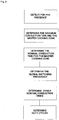
- the present invention proposes a system and method by which all of the quasi-resonant inverters (2) are operated at a common or master switching frequency. To this end, after each resonant coil (6) forming part of a certain cooking zone is determined, these resonant inductors (6) are energized according to predetermined current references and the maximum conduction time of each power switching device (IGBT (5)) in association with respective resonant coils (6) corresponding to a maximum predetermined current reference is determined.
- the resonant coil (6) in association with a power switching device (5) having the maximum conduction time at boost power level is determined as the master coil while the cooking zone containing the master coil becomes the master cooking zone.
- the power level setting of the master cooking zone as defined by the user is used to calculate the nominal conduction time of the master coil. For instance, if the maximum conduction time for the power switching device (5) of the master coil is determined as 18 ⁇ s and the power level setting of the associated cooking zone is 9 out of maximum 10, the actual or nominal conduction time for the master cooking zone will be 18*(9/10), which approximately equals 16 ⁇ s. Therefore, all the power switching devices (5) associated with the resonant coils (6) in all other cooking zones will be driven at a switching frequency in correspondence with a nominal conduction time of 16 ⁇ s.
- the switching frequency of the master coil and master cooking zone is used as the common or master frequency.
- the calculated nominal or actual on times for the power switching devices (5) of different resonant coils (6) is used in order for determining a specific duty cycle for each cooking zone in the following manner:
- the duty cycle of the power switching device (5) whose maximum conduction time is 15 ⁇ s and the nominal conduction time is calculated as 11 ⁇ s will have a duty cycle of 11/13, that is around 85% in a period T.
- the duty cycle will be 9/13 while the driving frequency is still the same with frequency of the master cooking zone having the master coil.
- the duty cycle is calculated as a number greater than 1, the respective power switching device (5) will be operational during the entire time period T.
- the present invention therefore provides that each and every resonant coil (6) in a flexible configuration cooking surface is energized with a common driving frequency determined by the power switching device (5) of the master coil in the master cooking zone, the power switching device (5) having the maximum conduction time.
- the present invention proposes an induction heating cooker (1) comprising a plurality of resonant inductors (6) in association with induction resonant inverters (2) supplied by a common DC bus in the manner that a multi-zone induction coil system is provided, a power switch driving circuit driving power switching devices (5) associated with the induction resonant inverters (2) and a pan detection circuit for detecting presence of a pan.
- a control circuitry (12) effects: a) detection of presence of at least two cooking pans, b) determination of a master resonant inductor (6) forming part of a master cooking zone by way of energizing all resonant coils (6) according to predetermined current references such that the maximum conduction time of each power switching device (5) in association with respective resonant coils (6) corresponding to a maximum predetermined current reference is determined, c) determination of nominal conduction time of the master cooking zone in reference to a power level setting adjusted for said master cooking zone and, d) determination of a common switching frequency in correspondence with the nominal conduction time of the master cooking zone to be applicable to all resonant inductors (6) of the induction heating cooker (1).
- the nominal conduction time of the master cooking zone is calculated in direct proportion to a power level setting adjusted for the master cooking zone.
- control circuitry (12) further effects calculation of nominal on times for power switching devices (5) associated with resonant inductors (6) in different cooking zones other than the master cooking zone based on different power settings as adjusted.
- calculated nominal on times for the power switching devices (5) of different resonant coils (6) than the resonant coils (6) of the master cooking zone is used in order for determining a specific duty cycle for each cooking zone.
- calculated nominal on time of a power switching device (5) of different resonant coils (6) than the resonant coils (6) of the master cooking zone is used as the numerator of a ratio determining the duty cycle of a respective power switching device (5) associated with said different resonant coils.
- the denominator of the ratio determining the duty cycle of the respective power switching device (5) associated with said different resonant coils is a predetermined common value.
- the denominator of the ratio determining the duty cycle is set as the lowest determined maximum conduction time of a given resonant inductor (6).
- a respective power switching device (5) in the case the duty cycle is calculated as a number greater than 1, a respective power switching device (5) will be operational during the entire time period T.
- a method for operating an induction heating cooker (1) comprising a plurality of resonant inductors (6) in association with induction resonant inverters (2) supplied by a common DC bus in the manner that a multi-zone induction coil system is provided, a power switch driving circuit driving power switching devices (5) associated with the induction resonant inverters (2) and a pan detection circuit for detecting presence of a pan, said method comprising the steps of, a) detecting presence of at least two cooking pans, b) determining a master resonant inductor (6) forming part of a master cooking zone by way of energizing all resonant coils (6) according to predetermined current references such that the maximum conduction time of each power switching device (5) in association with respective resonant coils (6) corresponding to a maximum predetermined current reference is determined, c) determining nominal conduction time of the master cooking zone in reference to a power level
- the efficient and advantageous method of the invention provides that an induction heating cooker (1) having induction resonant inverters (2) supplied from the same DC bus is operable by applying individual cooking zone power control such that individual cooking zones are powered at a master driving frequency, whereby audible noise caused by different operating frequencies is overcome.
Landscapes
- Physics & Mathematics (AREA)
- Electromagnetism (AREA)
- Induction Heating Cooking Devices (AREA)
- General Induction Heating (AREA)
Priority Applications (1)
| Application Number | Priority Date | Filing Date | Title |
|---|---|---|---|
| PL14816438T PL3170363T3 (pl) | 2014-07-15 | 2014-07-15 | Układ i sposób zmniejszania szumu generowanego przez wielostrefową kuchenkę indukcyjną zasilaną falownikiem quasi-rezonansowym |
Applications Claiming Priority (1)
| Application Number | Priority Date | Filing Date | Title |
|---|---|---|---|
| PCT/TR2014/000283 WO2016010492A1 (en) | 2014-07-15 | 2014-07-15 | System and method for improving noise performance of multi-zone quasi-resonant inverter induction heater |
Publications (2)
| Publication Number | Publication Date |
|---|---|
| EP3170363A1 EP3170363A1 (en) | 2017-05-24 |
| EP3170363B1 true EP3170363B1 (en) | 2018-04-11 |
Family
ID=52144811
Family Applications (1)
| Application Number | Title | Priority Date | Filing Date |
|---|---|---|---|
| EP14816438.7A Active EP3170363B1 (en) | 2014-07-15 | 2014-07-15 | System and method for improving noise performance of multi-zone quasi-resonant inverter induction heater |
Country Status (5)
| Country | Link |
|---|---|
| EP (1) | EP3170363B1 (pl) |
| ES (1) | ES2676898T3 (pl) |
| PL (1) | PL3170363T3 (pl) |
| TR (2) | TR201722621T3 (pl) |
| WO (1) | WO2016010492A1 (pl) |
Cited By (3)
| Publication number | Priority date | Publication date | Assignee | Title |
|---|---|---|---|---|
| US20220151430A1 (en) * | 2019-03-20 | 2022-05-19 | Electrolux Appliances Aktiebolag | Kitchen appliance |
| US20230189405A1 (en) * | 2021-12-10 | 2023-06-15 | Sabaf S.P.A. | Induction Cooktop and Method for Controlling an Induction Cooktop |
| EP4554328A1 (en) * | 2023-11-07 | 2025-05-14 | Whirlpool Corporation | Control methods of a current source inverter for induction cooking |
Families Citing this family (18)
| Publication number | Priority date | Publication date | Assignee | Title |
|---|---|---|---|---|
| ITTO20120896A1 (it) | 2012-10-15 | 2014-04-16 | Indesit Co Spa | Piano cottura a induzione |
| US10605464B2 (en) | 2012-10-15 | 2020-03-31 | Whirlpool Corporation | Induction cooktop |
| EP3282815B1 (en) * | 2016-08-08 | 2019-05-15 | Electrolux Appliances Aktiebolag | Method for controlling an induction hob |
| ES2673131B1 (es) * | 2016-12-19 | 2019-03-28 | Bsh Electrodomesticos Espana Sa | Dispositivo de aparato domestico de coccion por induccion con una matriz de elementos de calentamiento |
| EP3432682B1 (en) | 2017-07-18 | 2026-04-08 | Whirlpool Corporation | Method for operating an induction cooking hob and cooking hob using such method |
| EP3445135B1 (en) * | 2017-08-14 | 2020-05-27 | Electrolux Appliances Aktiebolag | Power module and cooking appliance |
| US10993292B2 (en) | 2017-10-23 | 2021-04-27 | Whirlpool Corporation | System and method for tuning an induction circuit |
| US11140751B2 (en) | 2018-04-23 | 2021-10-05 | Whirlpool Corporation | System and method for controlling quasi-resonant induction heating devices |
| US12588112B2 (en) | 2018-04-23 | 2026-03-24 | Whirlpool Corporation | System and method for controlling induction heating devices with series connected switching devices |
| US12302478B2 (en) | 2018-04-23 | 2025-05-13 | Whirlpool Corporation | Control circuits and methods for distributed induction heating devices |
| EP3582587B1 (en) | 2018-06-16 | 2022-09-28 | Electrolux Appliances Aktiebolag | Method for controlling two cooking zones of an induction cooking hob |
| CN110567007B (zh) * | 2019-09-17 | 2020-06-05 | 珠海格力电器股份有限公司 | 一种半桥电磁炉锅具检测方法、装置及半桥电磁炉 |
| US11910509B2 (en) | 2021-03-02 | 2024-02-20 | Whirlpool Corporation | Method for improving accuracy in load curves acquisition on an induction cooktop |
| CN115915518A (zh) * | 2021-08-25 | 2023-04-04 | 杭州九阳小家电有限公司 | 烹饪器具及其工况检测方法、控制方法和控制电路 |
| DE102022202805A1 (de) | 2022-03-22 | 2023-09-28 | E.G.O. Elektro-Gerätebau GmbH | Verfahren zum Betrieb eines Induktionskochfelds und Induktionskochfeld |
| CN114828317A (zh) * | 2022-06-27 | 2022-07-29 | 中山爱它电器科技有限公司 | 一种多线圈电磁感应电路以及加热方法 |
| CN119922775B (zh) * | 2023-10-31 | 2026-03-17 | 佛山市顺德区美的电热电器制造有限公司 | 电磁加热电路、电器设备的控制方法、装置及电器设备 |
| CN117639515B (zh) * | 2023-11-30 | 2024-10-01 | 苏州海鹏科技有限公司 | 基于dsp的准谐振反激电路控制方法 |
Family Cites Families (4)
| Publication number | Priority date | Publication date | Assignee | Title |
|---|---|---|---|---|
| WO2004107819A1 (en) | 2003-05-28 | 2004-12-09 | Tubitak-Bilten (Turkiye Bilimsel Ve Teknik Arastirma Kurumu-Bilgi Teknolojileri Ve Elektronik Arastirma Enstitusu) | Induction cooktop |
| FR2863039B1 (fr) * | 2003-11-27 | 2006-02-17 | Brandt Ind | Procede de chauffage d'un recipient pose sur une table de cuisson a moyens de chauffage associe a des inducteurs |
| ES2678069T3 (es) * | 2010-11-16 | 2018-08-08 | Mitsubishi Electric Corporation | Sistema de cocina de calentamiento por inducción y proceso para controlarlo |
| EP2731402B1 (en) * | 2012-11-09 | 2015-08-19 | Electrolux Home Products Corporation N.V. | A method for controlling an induction cooking hob with a plurality of induction coils and an induction cooking hob |
-
2014
- 2014-07-15 TR TR2017/22621T patent/TR201722621T3/tr unknown
- 2014-07-15 PL PL14816438T patent/PL3170363T3/pl unknown
- 2014-07-15 ES ES14816438.7T patent/ES2676898T3/es active Active
- 2014-07-15 EP EP14816438.7A patent/EP3170363B1/en active Active
- 2014-07-15 WO PCT/TR2014/000283 patent/WO2016010492A1/en not_active Ceased
-
2015
- 2015-06-23 TR TR2015/07682A patent/TR201507682A3/tr unknown
Cited By (4)
| Publication number | Priority date | Publication date | Assignee | Title |
|---|---|---|---|---|
| US20220151430A1 (en) * | 2019-03-20 | 2022-05-19 | Electrolux Appliances Aktiebolag | Kitchen appliance |
| US12279715B2 (en) * | 2019-03-20 | 2025-04-22 | Electrolux Appliances Aktiebolag | Kitchen appliance |
| US20230189405A1 (en) * | 2021-12-10 | 2023-06-15 | Sabaf S.P.A. | Induction Cooktop and Method for Controlling an Induction Cooktop |
| EP4554328A1 (en) * | 2023-11-07 | 2025-05-14 | Whirlpool Corporation | Control methods of a current source inverter for induction cooking |
Also Published As
| Publication number | Publication date |
|---|---|
| ES2676898T3 (es) | 2018-07-26 |
| PL3170363T3 (pl) | 2018-10-31 |
| TR201722621T3 (tr) | 2019-05-21 |
| EP3170363A1 (en) | 2017-05-24 |
| WO2016010492A1 (en) | 2016-01-21 |
| TR201507682A3 (tr) | 2017-06-21 |
Similar Documents
| Publication | Publication Date | Title |
|---|---|---|
| EP3170363B1 (en) | System and method for improving noise performance of multi-zone quasi-resonant inverter induction heater | |
| EP2932794B1 (en) | An induction heating cooktop | |
| EP3042541B1 (en) | Quasi-resonant induction heater having cookware position sensing circuit | |
| EP3050398B1 (en) | Synchronization circuit for powering cooktop dual induction coil heating zone | |
| US20090057298A1 (en) | Device for Inductive Energy Transmission with Resonant Circuit | |
| US11064573B2 (en) | Determining resonant frequency for quasi-resonant induction cooking devices | |
| WO2004107819A1 (en) | Induction cooktop | |
| US10477624B2 (en) | Systems and methods of quasi-resonant induction heating | |
| WO2014090874A1 (en) | An induction heating cooktop | |
| EP2939499B1 (en) | An induction heating cooktop | |
| EP3170362B1 (en) | System and method enabling modification of cookware positioning in an induction heating cooker | |
| EP3170364A1 (en) | Induction heating cooker enabling improved power setting control | |
| US20180176998A1 (en) | Evaluating zero-voltage switching condition of quasi-resonant inverters in induction cooktops | |
| WO2014090872A1 (en) | An induction heating cooktop | |
| WO2016029959A1 (en) | Induction heating cooker cooking utensil positioning safety arrangement | |
| RU2313924C2 (ru) | Индукционная варочная панель | |
| EP3111722B1 (en) | Induction cooker half-bridge resonant inverter having an adaptor coil | |
| EP4106490A1 (en) | Induction cooking appliance | |
| JP2012049019A (ja) | 誘導加熱調理器 | |
| Renuka et al. | Systematic Approach to High Efficiency Resonant Converter used in Domestic Heating Application. | |
| KR20170068750A (ko) | 유도가열 조리기의 인버터 스위칭 소자 보호장치 |
Legal Events
| Date | Code | Title | Description |
|---|---|---|---|
| PUAI | Public reference made under article 153(3) epc to a published international application that has entered the european phase |
Free format text: ORIGINAL CODE: 0009012 |
|
| 17P | Request for examination filed |
Effective date: 20161223 |
|
| AK | Designated contracting states |
Kind code of ref document: A1 Designated state(s): AL AT BE BG CH CY CZ DE DK EE ES FI FR GB GR HR HU IE IS IT LI LT LU LV MC MK MT NL NO PL PT RO RS SE SI SK SM TR |
|
| AX | Request for extension of the european patent |
Extension state: BA ME |
|
| DAX | Request for extension of the european patent (deleted) | ||
| GRAP | Despatch of communication of intention to grant a patent |
Free format text: ORIGINAL CODE: EPIDOSNIGR1 |
|
| INTG | Intention to grant announced |
Effective date: 20180105 |
|
| GRAS | Grant fee paid |
Free format text: ORIGINAL CODE: EPIDOSNIGR3 |
|
| GRAA | (expected) grant |
Free format text: ORIGINAL CODE: 0009210 |
|
| AK | Designated contracting states |
Kind code of ref document: B1 Designated state(s): AL AT BE BG CH CY CZ DE DK EE ES FI FR GB GR HR HU IE IS IT LI LT LU LV MC MK MT NL NO PL PT RO RS SE SI SK SM TR |
|
| REG | Reference to a national code |
Ref country code: GB Ref legal event code: FG4D |
|
| REG | Reference to a national code |
Ref country code: CH Ref legal event code: EP |
|
| REG | Reference to a national code |
Ref country code: AT Ref legal event code: REF Ref document number: 989345 Country of ref document: AT Kind code of ref document: T Effective date: 20180415 |
|
| REG | Reference to a national code |
Ref country code: IE Ref legal event code: FG4D |
|
| REG | Reference to a national code |
Ref country code: DE Ref legal event code: R096 Ref document number: 602014023868 Country of ref document: DE |
|
| REG | Reference to a national code |
Ref country code: ES Ref legal event code: FG2A Ref document number: 2676898 Country of ref document: ES Kind code of ref document: T3 Effective date: 20180726 |
|
| REG | Reference to a national code |
Ref country code: FR Ref legal event code: PLFP Year of fee payment: 5 |
|
| REG | Reference to a national code |
Ref country code: SE Ref legal event code: TRGR |
|
| REG | Reference to a national code |
Ref country code: NL Ref legal event code: MP Effective date: 20180411 |
|
| REG | Reference to a national code |
Ref country code: LT Ref legal event code: MG4D |
|
| REG | Reference to a national code |
Ref country code: NO Ref legal event code: T2 Effective date: 20180411 |
|
| PG25 | Lapsed in a contracting state [announced via postgrant information from national office to epo] |
Ref country code: NL Free format text: LAPSE BECAUSE OF FAILURE TO SUBMIT A TRANSLATION OF THE DESCRIPTION OR TO PAY THE FEE WITHIN THE PRESCRIBED TIME-LIMIT Effective date: 20180411 |
|
| PG25 | Lapsed in a contracting state [announced via postgrant information from national office to epo] |
Ref country code: FI Free format text: LAPSE BECAUSE OF FAILURE TO SUBMIT A TRANSLATION OF THE DESCRIPTION OR TO PAY THE FEE WITHIN THE PRESCRIBED TIME-LIMIT Effective date: 20180411 Ref country code: LT Free format text: LAPSE BECAUSE OF FAILURE TO SUBMIT A TRANSLATION OF THE DESCRIPTION OR TO PAY THE FEE WITHIN THE PRESCRIBED TIME-LIMIT Effective date: 20180411 Ref country code: BG Free format text: LAPSE BECAUSE OF FAILURE TO SUBMIT A TRANSLATION OF THE DESCRIPTION OR TO PAY THE FEE WITHIN THE PRESCRIBED TIME-LIMIT Effective date: 20180711 Ref country code: AL Free format text: LAPSE BECAUSE OF FAILURE TO SUBMIT A TRANSLATION OF THE DESCRIPTION OR TO PAY THE FEE WITHIN THE PRESCRIBED TIME-LIMIT Effective date: 20180411 |
|
| PG25 | Lapsed in a contracting state [announced via postgrant information from national office to epo] |
Ref country code: HR Free format text: LAPSE BECAUSE OF FAILURE TO SUBMIT A TRANSLATION OF THE DESCRIPTION OR TO PAY THE FEE WITHIN THE PRESCRIBED TIME-LIMIT Effective date: 20180411 Ref country code: RS Free format text: LAPSE BECAUSE OF FAILURE TO SUBMIT A TRANSLATION OF THE DESCRIPTION OR TO PAY THE FEE WITHIN THE PRESCRIBED TIME-LIMIT Effective date: 20180411 Ref country code: LV Free format text: LAPSE BECAUSE OF FAILURE TO SUBMIT A TRANSLATION OF THE DESCRIPTION OR TO PAY THE FEE WITHIN THE PRESCRIBED TIME-LIMIT Effective date: 20180411 Ref country code: GR Free format text: LAPSE BECAUSE OF FAILURE TO SUBMIT A TRANSLATION OF THE DESCRIPTION OR TO PAY THE FEE WITHIN THE PRESCRIBED TIME-LIMIT Effective date: 20180712 |
|
| REG | Reference to a national code |
Ref country code: AT Ref legal event code: MK05 Ref document number: 989345 Country of ref document: AT Kind code of ref document: T Effective date: 20180411 |
|
| PG25 | Lapsed in a contracting state [announced via postgrant information from national office to epo] |
Ref country code: PT Free format text: LAPSE BECAUSE OF FAILURE TO SUBMIT A TRANSLATION OF THE DESCRIPTION OR TO PAY THE FEE WITHIN THE PRESCRIBED TIME-LIMIT Effective date: 20180813 |
|
| REG | Reference to a national code |
Ref country code: DE Ref legal event code: R097 Ref document number: 602014023868 Country of ref document: DE |
|
| PG25 | Lapsed in a contracting state [announced via postgrant information from national office to epo] |
Ref country code: DK Free format text: LAPSE BECAUSE OF FAILURE TO SUBMIT A TRANSLATION OF THE DESCRIPTION OR TO PAY THE FEE WITHIN THE PRESCRIBED TIME-LIMIT Effective date: 20180411 Ref country code: CZ Free format text: LAPSE BECAUSE OF FAILURE TO SUBMIT A TRANSLATION OF THE DESCRIPTION OR TO PAY THE FEE WITHIN THE PRESCRIBED TIME-LIMIT Effective date: 20180411 Ref country code: SK Free format text: LAPSE BECAUSE OF FAILURE TO SUBMIT A TRANSLATION OF THE DESCRIPTION OR TO PAY THE FEE WITHIN THE PRESCRIBED TIME-LIMIT Effective date: 20180411 Ref country code: RO Free format text: LAPSE BECAUSE OF FAILURE TO SUBMIT A TRANSLATION OF THE DESCRIPTION OR TO PAY THE FEE WITHIN THE PRESCRIBED TIME-LIMIT Effective date: 20180411 Ref country code: EE Free format text: LAPSE BECAUSE OF FAILURE TO SUBMIT A TRANSLATION OF THE DESCRIPTION OR TO PAY THE FEE WITHIN THE PRESCRIBED TIME-LIMIT Effective date: 20180411 Ref country code: AT Free format text: LAPSE BECAUSE OF FAILURE TO SUBMIT A TRANSLATION OF THE DESCRIPTION OR TO PAY THE FEE WITHIN THE PRESCRIBED TIME-LIMIT Effective date: 20180411 |
|
| PLBE | No opposition filed within time limit |
Free format text: ORIGINAL CODE: 0009261 |
|
| STAA | Information on the status of an ep patent application or granted ep patent |
Free format text: STATUS: NO OPPOSITION FILED WITHIN TIME LIMIT |
|
| PG25 | Lapsed in a contracting state [announced via postgrant information from national office to epo] |
Ref country code: SM Free format text: LAPSE BECAUSE OF FAILURE TO SUBMIT A TRANSLATION OF THE DESCRIPTION OR TO PAY THE FEE WITHIN THE PRESCRIBED TIME-LIMIT Effective date: 20180411 |
|
| REG | Reference to a national code |
Ref country code: CH Ref legal event code: PL |
|
| 26N | No opposition filed |
Effective date: 20190114 |
|
| PG25 | Lapsed in a contracting state [announced via postgrant information from national office to epo] |
Ref country code: MC Free format text: LAPSE BECAUSE OF FAILURE TO SUBMIT A TRANSLATION OF THE DESCRIPTION OR TO PAY THE FEE WITHIN THE PRESCRIBED TIME-LIMIT Effective date: 20180411 Ref country code: LU Free format text: LAPSE BECAUSE OF NON-PAYMENT OF DUE FEES Effective date: 20180715 |
|
| REG | Reference to a national code |
Ref country code: BE Ref legal event code: MM Effective date: 20180731 |
|
| REG | Reference to a national code |
Ref country code: IE Ref legal event code: MM4A |
|
| PG25 | Lapsed in a contracting state [announced via postgrant information from national office to epo] |
Ref country code: CH Free format text: LAPSE BECAUSE OF NON-PAYMENT OF DUE FEES Effective date: 20180731 Ref country code: IE Free format text: LAPSE BECAUSE OF NON-PAYMENT OF DUE FEES Effective date: 20180715 Ref country code: LI Free format text: LAPSE BECAUSE OF NON-PAYMENT OF DUE FEES Effective date: 20180731 |
|
| PG25 | Lapsed in a contracting state [announced via postgrant information from national office to epo] |
Ref country code: SI Free format text: LAPSE BECAUSE OF FAILURE TO SUBMIT A TRANSLATION OF THE DESCRIPTION OR TO PAY THE FEE WITHIN THE PRESCRIBED TIME-LIMIT Effective date: 20180411 Ref country code: BE Free format text: LAPSE BECAUSE OF NON-PAYMENT OF DUE FEES Effective date: 20180731 |
|
| PGFP | Annual fee paid to national office [announced via postgrant information from national office to epo] |
Ref country code: DE Payment date: 20190719 Year of fee payment: 6 Ref country code: NO Payment date: 20190723 Year of fee payment: 6 Ref country code: IT Payment date: 20190730 Year of fee payment: 6 Ref country code: SE Payment date: 20190719 Year of fee payment: 6 |
|
| PGFP | Annual fee paid to national office [announced via postgrant information from national office to epo] |
Ref country code: PL Payment date: 20190710 Year of fee payment: 6 |
|
| PG25 | Lapsed in a contracting state [announced via postgrant information from national office to epo] |
Ref country code: MT Free format text: LAPSE BECAUSE OF NON-PAYMENT OF DUE FEES Effective date: 20180715 |
|
| PG25 | Lapsed in a contracting state [announced via postgrant information from national office to epo] |
Ref country code: MK Free format text: LAPSE BECAUSE OF NON-PAYMENT OF DUE FEES Effective date: 20180411 Ref country code: HU Free format text: LAPSE BECAUSE OF FAILURE TO SUBMIT A TRANSLATION OF THE DESCRIPTION OR TO PAY THE FEE WITHIN THE PRESCRIBED TIME-LIMIT; INVALID AB INITIO Effective date: 20140715 Ref country code: CY Free format text: LAPSE BECAUSE OF FAILURE TO SUBMIT A TRANSLATION OF THE DESCRIPTION OR TO PAY THE FEE WITHIN THE PRESCRIBED TIME-LIMIT Effective date: 20180411 |
|
| PG25 | Lapsed in a contracting state [announced via postgrant information from national office to epo] |
Ref country code: IS Free format text: LAPSE BECAUSE OF FAILURE TO SUBMIT A TRANSLATION OF THE DESCRIPTION OR TO PAY THE FEE WITHIN THE PRESCRIBED TIME-LIMIT Effective date: 20180811 |
|
| REG | Reference to a national code |
Ref country code: DE Ref legal event code: R119 Ref document number: 602014023868 Country of ref document: DE |
|
| REG | Reference to a national code |
Ref country code: NO Ref legal event code: MMEP |
|
| REG | Reference to a national code |
Ref country code: SE Ref legal event code: EUG |
|
| PG25 | Lapsed in a contracting state [announced via postgrant information from national office to epo] |
Ref country code: NO Free format text: LAPSE BECAUSE OF NON-PAYMENT OF DUE FEES Effective date: 20200731 |
|
| PG25 | Lapsed in a contracting state [announced via postgrant information from national office to epo] |
Ref country code: SE Free format text: LAPSE BECAUSE OF NON-PAYMENT OF DUE FEES Effective date: 20200716 Ref country code: DE Free format text: LAPSE BECAUSE OF NON-PAYMENT OF DUE FEES Effective date: 20210202 |
|
| PG25 | Lapsed in a contracting state [announced via postgrant information from national office to epo] |
Ref country code: IT Free format text: LAPSE BECAUSE OF NON-PAYMENT OF DUE FEES Effective date: 20200715 |
|
| PG25 | Lapsed in a contracting state [announced via postgrant information from national office to epo] |
Ref country code: PL Free format text: LAPSE BECAUSE OF NON-PAYMENT OF DUE FEES Effective date: 20200715 |
|
| PGFP | Annual fee paid to national office [announced via postgrant information from national office to epo] |
Ref country code: FR Payment date: 20240730 Year of fee payment: 11 |
|
| PGFP | Annual fee paid to national office [announced via postgrant information from national office to epo] |
Ref country code: ES Payment date: 20240828 Year of fee payment: 11 |
|
| PGFP | Annual fee paid to national office [announced via postgrant information from national office to epo] |
Ref country code: GB Payment date: 20250722 Year of fee payment: 12 |
|
| PG25 | Lapsed in a contracting state [announced via postgrant information from national office to epo] |
Ref country code: FR Free format text: LAPSE BECAUSE OF NON-PAYMENT OF DUE FEES Effective date: 20250731 |