EP3170565B1 - Aérographe de type siphon - Google Patents
Aérographe de type siphon Download PDFInfo
- Publication number
- EP3170565B1 EP3170565B1 EP16805710.7A EP16805710A EP3170565B1 EP 3170565 B1 EP3170565 B1 EP 3170565B1 EP 16805710 A EP16805710 A EP 16805710A EP 3170565 B1 EP3170565 B1 EP 3170565B1
- Authority
- EP
- European Patent Office
- Prior art keywords
- nozzle
- handle
- sprayer
- disposed
- rod
- Prior art date
- Legal status (The legal status is an assumption and is not a legal conclusion. Google has not performed a legal analysis and makes no representation as to the accuracy of the status listed.)
- Not-in-force
Links
- 238000007789 sealing Methods 0.000 claims description 38
- 229910000831 Steel Inorganic materials 0.000 claims description 21
- 239000010959 steel Substances 0.000 claims description 21
- 230000000694 effects Effects 0.000 claims description 13
- 239000003973 paint Substances 0.000 description 12
- 238000009434 installation Methods 0.000 description 5
- 238000004519 manufacturing process Methods 0.000 description 4
- 238000006073 displacement reaction Methods 0.000 description 2
- 238000000034 method Methods 0.000 description 2
- 238000010422 painting Methods 0.000 description 2
- 238000005507 spraying Methods 0.000 description 2
- 230000009286 beneficial effect Effects 0.000 description 1
- 238000004040 coloring Methods 0.000 description 1
- 238000005034 decoration Methods 0.000 description 1
- 230000007547 defect Effects 0.000 description 1
- 238000003197 gene knockdown Methods 0.000 description 1
- 230000005484 gravity Effects 0.000 description 1
- 238000002955 isolation Methods 0.000 description 1
- 238000012986 modification Methods 0.000 description 1
- 230000004048 modification Effects 0.000 description 1
Images


Classifications
-
- B—PERFORMING OPERATIONS; TRANSPORTING
- B05—SPRAYING OR ATOMISING IN GENERAL; APPLYING FLUENT MATERIALS TO SURFACES, IN GENERAL
- B05B—SPRAYING APPARATUS; ATOMISING APPARATUS; NOZZLES
- B05B7/00—Spraying apparatus for discharge of liquids or other fluent materials from two or more sources, e.g. of liquid and air, of powder and gas
- B05B7/24—Spraying apparatus for discharge of liquids or other fluent materials from two or more sources, e.g. of liquid and air, of powder and gas with means, e.g. a container, for supplying liquid or other fluent material to a discharge device
- B05B7/2402—Apparatus to be carried on or by a person, e.g. by hand; Apparatus comprising containers fixed to the discharge device
- B05B7/2405—Apparatus to be carried on or by a person, e.g. by hand; Apparatus comprising containers fixed to the discharge device using an atomising fluid as carrying fluid for feeding, e.g. by suction or pressure, a carried liquid from the container to the nozzle
- B05B7/2435—Apparatus to be carried on or by a person, e.g. by hand; Apparatus comprising containers fixed to the discharge device using an atomising fluid as carrying fluid for feeding, e.g. by suction or pressure, a carried liquid from the container to the nozzle the carried liquid and the main stream of atomising fluid being brought together by parallel conduits placed one inside the other
-
- B—PERFORMING OPERATIONS; TRANSPORTING
- B05—SPRAYING OR ATOMISING IN GENERAL; APPLYING FLUENT MATERIALS TO SURFACES, IN GENERAL
- B05B—SPRAYING APPARATUS; ATOMISING APPARATUS; NOZZLES
- B05B1/00—Nozzles, spray heads or other outlets, with or without auxiliary devices such as valves, heating means
- B05B1/30—Nozzles, spray heads or other outlets, with or without auxiliary devices such as valves, heating means designed to control volume of flow, e.g. with adjustable passages
- B05B1/3033—Nozzles, spray heads or other outlets, with or without auxiliary devices such as valves, heating means designed to control volume of flow, e.g. with adjustable passages the control being effected by relative coaxial longitudinal movement of the controlling element and the spray head
- B05B1/304—Nozzles, spray heads or other outlets, with or without auxiliary devices such as valves, heating means designed to control volume of flow, e.g. with adjustable passages the control being effected by relative coaxial longitudinal movement of the controlling element and the spray head the controlling element being a lift valve
- B05B1/3046—Nozzles, spray heads or other outlets, with or without auxiliary devices such as valves, heating means designed to control volume of flow, e.g. with adjustable passages the control being effected by relative coaxial longitudinal movement of the controlling element and the spray head the controlling element being a lift valve the valve element, e.g. a needle, co-operating with a valve seat located downstream of the valve element and its actuating means, generally in the proximity of the outlet orifice
-
- B—PERFORMING OPERATIONS; TRANSPORTING
- B05—SPRAYING OR ATOMISING IN GENERAL; APPLYING FLUENT MATERIALS TO SURFACES, IN GENERAL
- B05B—SPRAYING APPARATUS; ATOMISING APPARATUS; NOZZLES
- B05B12/00—Arrangements for controlling delivery; Arrangements for controlling the spray area
- B05B12/002—Manually-actuated controlling means, e.g. push buttons, levers or triggers
-
- B—PERFORMING OPERATIONS; TRANSPORTING
- B05—SPRAYING OR ATOMISING IN GENERAL; APPLYING FLUENT MATERIALS TO SURFACES, IN GENERAL
- B05B—SPRAYING APPARATUS; ATOMISING APPARATUS; NOZZLES
- B05B7/00—Spraying apparatus for discharge of liquids or other fluent materials from two or more sources, e.g. of liquid and air, of powder and gas
- B05B7/02—Spray pistols; Apparatus for discharge
- B05B7/06—Spray pistols; Apparatus for discharge with at least one outlet orifice surrounding another approximately in the same plane
- B05B7/062—Spray pistols; Apparatus for discharge with at least one outlet orifice surrounding another approximately in the same plane with only one liquid outlet and at least one gas outlet
- B05B7/063—Spray pistols; Apparatus for discharge with at least one outlet orifice surrounding another approximately in the same plane with only one liquid outlet and at least one gas outlet one fluid being sucked by the other
- B05B7/064—Spray pistols; Apparatus for discharge with at least one outlet orifice surrounding another approximately in the same plane with only one liquid outlet and at least one gas outlet one fluid being sucked by the other the liquid being sucked by the gas
-
- B—PERFORMING OPERATIONS; TRANSPORTING
- B05—SPRAYING OR ATOMISING IN GENERAL; APPLYING FLUENT MATERIALS TO SURFACES, IN GENERAL
- B05B—SPRAYING APPARATUS; ATOMISING APPARATUS; NOZZLES
- B05B7/00—Spraying apparatus for discharge of liquids or other fluent materials from two or more sources, e.g. of liquid and air, of powder and gas
- B05B7/02—Spray pistols; Apparatus for discharge
- B05B7/12—Spray pistols; Apparatus for discharge designed to control volume of flow, e.g. with adjustable passages
- B05B7/1209—Spray pistols; Apparatus for discharge designed to control volume of flow, e.g. with adjustable passages the controlling means for each liquid or other fluent material being manual and interdependent
- B05B7/1218—With means for adjusting or modifying the action of the controlling means
Definitions
- the invention relates to the technical field of airbrushes, in particular to a siphon-type airbrush.
- Airbrushes are important painting tools capable of spraying vaporific paint to fulfill the aim of uniform coloring, widely used in the fields of decoration design, outdoor advertisement, publication printing, movies and cartoons.
- Common airbrushes on the market are mainly classified into gravity type and siphon-type according to the paint delivery mode.
- the principle of the siphon-type airbrush is that compressed air is used to generate a negative pressure at the position of the nozzle such that the paint in the paint bottle is siphoned into the nozzle to be sprayed out.
- the nozzle thereof is usually installed at the front end of a front handle by means of a sprayer.
- the objective of the invention is to provide a siphon-type airbrush which has a simple and rational structure, low manufacturing cost, high stability and is conveniently processed and used, to overcome the defects and shortcomings in the prior art.
- a siphon-type airbrush of the invention includes a front handle, a tail handle, a needle, a sprayer, a nozzle and an air inlet valve.
- the front handle is matched and connected with the tail handle to form an airbrush body.
- the airbrush body is internally formed with an accommodating cavity.
- the accommodating cavity is internally provided with a needle.
- a feeding joint is disposed on the wall of the front handle.
- the front handle is internally provided with a siphon channel which communicates with the feeding joint.
- the air inlet valve is disposed at the middle part of the airbrush body.
- the accommodating cavity is internally provided with a trigger for controlling the on-off of the air inlet valve. The triggering end of the trigger extends out of the front handle.
- the trigger is matched with the needle in a linkage way.
- the airbrush also includes a nozzle base; the rear end of the nozzle base is in threaded connection with the front handle; and the front end of the nozzle base is in threaded connection with the sprayer.
- the nozzle includes a nozzle body; the nozzle body is pressed between the sprayer and the nozzle base; and the front end of the nozzle body extends to form a nozzle tip.
- An axial through-hole is disposed in the center of the nozzle base.
- the siphon channel communicates with the axial through-hole.
- the front end of the needle passes through the axial through-hole and the nozzle body extends into the nozzle tip.
- An air chamber is formed among the sprayer, the nozzle body and the nozzle tip.
- the front handle, the nozzle base and the nozzle body are matched to form an air channel which connects the air outlet of the air inlet valve and the air chamber.
- a radial gap which connects the air chamber and the surrounding air is formed between the front end of the sprayer and the nozzle tip.
- sealing rings are respectively disposed between the front handle and the nozzle base, between the nozzle base and the sprayer, and between the nozzle base and the nozzle body.
- the accommodating cavity is also internally provided with an ejector rod; the front end of the ejector rod is axially provided with a slot to be inserted by the needle; and the rear end of the ejector rod extends out of the tail handle and is fixedly connected with a button.
- the needle is fixedly connected with a locking nut which is matched with the front end of the ejector rod in a stopping way.
- a tail handle screw is disposed between the ejector rod and the tail handle in a sleeving way. The tail handle screw is in threaded connection with the tail handle.
- a locking sleeve is movably connected between the tail handle screw and the button.
- a pair of mounting holes is symmetrically disposed on the wall of the tail handle screw.
- Each of the mounting holes is internally and movably equipped with a steel ball.
- the outer circumference of the rear end of the ejector rod is provided with a first step portion and a second step portion, which are matched with the steel balls, in turn from the front to the rear.
- the diameter of the first step portion is greater than that of the second step portion.
- An annular deep well and an annular shallow well which are matched with the steel balls, are disposed on the inner wall of the locking sleeve in turn from the front to the rear.
- the annular deep well and the annular shallow well run through each other.
- a limiting boss matched with the rear end of the tail handle screw in a stopping way is disposed at the middle part of the locking sleeve.
- a button spring is disposed between the limiting boss and the button.
- the front handle and the tail handle are connected through a connecting screw; the exterior of the needle is respectively sleeved with an adjusting rod and a spring adjusting screw; an adjusting rod spring is disposed between the adjusting rod and the spring adjusting screw; the rear end of the adjusting rod passes through the spring adjusting screw and then is in threaded connection with the locking nut; the rear end of the adjusting rod is axially provided with a clamping groove; when the locking nut is in threaded connection with the adjusting rod, the rear end of the adjusting rod shrinks with the stress and clamps the needle by the effect of the clamping groove; and the spring adjusting screw is in threaded connection with the connecting screw.
- the trigger is provided with a linkage block for driving the needle to move axially;
- the linkage block is an eccentric arc structure; the outer circumference of the linkage block is pressed against the adjusting rod; the front end of the adjusting rod extends to form a connecting portion; and one end, away from the trigger, of the linkage block is movably sleeved with the connecting portion.
- the tail handle is provided with a gap at a position corresponding to the spring adjusting screw.
- the air inlet valve comprises a valve body; one end of the valve body is fixedly connected with the front handle; the other end of the valve body is provided with an air inlet connector; the valve body is provided with an air outlet; the air inlet connector is internally provided with a valve rod and a switching hole, respectively; one end of the valve rod passes through the switching hole and the valve body in turn and is pressed against the trigger; the other end of the valve rod is provided with a sealing base matched with the switching hole in a sealing way; the air inlet connector is also internally provided with a valve rod adjusting screw; and an air inlet valve spring is disposed between the valve rod adjusting screw and one end, close to the sealing base, of the valve rod .
- the accommodating cavity is internally provided with a tapered sealing ring and a sealing ring cap in turn from the front to the rear; the sealing ring cap and the tapered sealing ring are both disposed between the nozzle base and the trigger; the sealing ring cap is in threaded connection with the front handle; and the tapered sealing ring is pressed between the front handle and the sealing ring cap.
- the exterior of the sprayer is connected and provided with a sprayer sleeve.
- the front end of the front handle is in threaded connection with the nozzle base, realizing installation and fixation of the sprayer and the nozzle through the nozzle base; compared with the prior art where the front handle is directly equipped with the nozzle through the sprayer, the invention effectively optimizes the connection structure of the front handle, simplifies the structure setting of the front handle, and brings more convenience in processing of the air channel in the front handle, so the processing is convenient and the manufacturing cost is reduced; besides, the nozzle body is pressed between the sprayer and the nozzle base, which makes the assembling of the nozzle quick and convenient, effectively improves the stability of the nozzle position state, aids adequate assurance of the coaxiality between the nozzle tip and the sprayer, and improves the use effect of the invention.
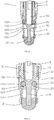
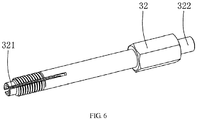
- FIG. 1-6 1. Front handle; 11. feeding joint; 12. siphon channel; 2. tail handle; 21. connecting screw; 22. gap; 3. needle; 31. locking nut; 32. adjusting rod; 321. clamping groove; 322. connecting portion; 33. spring adjusting screw; 34. adjusting rod spring; 4. sprayer; 41. sprayer sleeve; 51. nozzle body; 52. nozzle tip; 61. valve body; 62. air inlet connector; 63. air outlet; 64. valve rod; 65. switching hole; 66. sealing base; 67. valve rod adjusting screw; 68. inlet valve spring; 7. accommodating cavity; 71. trigger; 711. linkage block; 72. tapered sealing ring; 73.sealing ring cap; 8.
- nozzle base 81. axial through-hole; 82. air channel; 83. sealing ring; 9. ejector rod; 91. slot; 92. first step portion; 93. second step portion; 10. button; 101 button spring; 111 tail handle screw; 112. steel ball; 121. locking sleeve; 122. annular deep well; 123. annular shallow well; 124. limiting boss; A. air chamber.
- a siphon airbrush includes a front handle 1, a tail handle 2, a needle 3, a sprayer 4, a nozzle and an air inlet valve.
- the front handle 1 is matched and connected with the tail handle 2 to form an airbrush body.
- An accommodating cavity 7 is formed in the airbrush body.
- the accommodating cavity 7 is internally provided with the needle 3.
- a feeding joint 11 is disposed on the wall of the front handle 1.
- the feeding joint 11 is used for connecting a paint bottle.
- the front handle 1 is internally provided with a siphon channel 12 which communicates with the feeding joint 11.
- the air inlet valve is disposed at the middle part of the airbrush body.
- the accommodating cavity 7 is internally provided with a trigger 71 for controlling the on-off of the air inlet valve.
- a triggering end of the trigger 71 extends out of the front handle 1.
- the trigger 71 is matched with the needle 3 in a linkage way.
- the siphon-type airbrush also includes a nozzle base 8.
- the rear end of the nozzle base 8 is in threaded connection with the front handle 1.
- the front end of the nozzle base 8 is in threaded connection with the sprayer 4.
- the exterior of the sprayer 4 is connected and provided with a sprayer sleeve 41.
- the sprayer sleeve 41 is used for protecting the needle 3.
- the nozzle includes a nozzle body 51.
- the nozzle body 51 is pressed between the sprayer 4 and the nozzle base 8.
- the front end of the nozzle body 51 extends to form a nozzle tip 52.
- An axial through-hole 81 is formed in the center of the nozzle base 8.
- the siphon channel 12 communicates with the axial through-hole 81.
- the front end of the needle 3 passes through the axial through-hole 81 and the nozzle body 51 and then extends into the nozzle tip 52.
- An air chamber A is formed among the sprayer 4, the nozzle body 51 and the nozzle tip 52.
- the front handle 1, the nozzle base 8 and the nozzle body 51 are matched to form an air channel 82 which connects an air outlet 63 of the air inlet valve and the air chamber A.
- a radial gap which connects the air chamber A and the surrounding air is formed between the front end of the sprayer 4 and the nozzle tip 52.
- the front end of the front handle 1 is in threaded connection with the nozzle base 8, realizing installation and fixation of the sprayer 4 and the nozzle through the nozzle base 8.
- the invention effectively optimizes the connection structure of the front handle 1, simplifies the structure setting of the front handle 1, and brings more convenience in processing of the air channel 82 in the front handle 1, so the processing is convenient and the manufacturing cost is reduced.
- the nozzle body 51 is pressed between the sprayer 4 and the nozzle base 8, which makes the assembling of the nozzle quick and convenient, effectively improves the stability of the nozzle position state, aids adequate assurance of the coaxiality between the nozzle tip 52 and the sprayer 4, and improves the use effect of the invention.
- compressed air passes through the air inlet valve and the air channel 82 in turn and then enters the air chamber A, and is sprayed out via the radial gap between the front end of the sprayer 4 and the nozzle tip 52.
- the compressed air near the front end of the sprayer 4 generates a negative pressure at the position of the nozzle tip 52 to suck the paint in the siphon channel 12 from the nozzle, and the paint is atomized by the compressed air sprayed from the front end of the sprayer 4 while being sprayed via the nozzle tip 52, thus realizing the atomized painting effect.
- Sealing rings 83 are respectively disposed between the front handle 1 and the nozzle base 8, between the nozzle base 8 and the sprayer 4, and between the nozzle base 8 and the nozzle body 51.
- the accommodating cavity 7 is also internally provided with an ejector rod 9.
- the front end of the ejector rod 9 is axially provided with a slot 91 to be inserted by the needle 3.
- the rear end of the ejector rod 9 extends out of the tail handle 2 and is fixedly connected with a button 10.
- the needle 3 is fixedly connected with a locking nut 31 which is matched with the front end of the ejector rod 9 in a stopping way.
- a tail handle screw 111 is disposed between the ejector rod 9 and the tail handle 2.
- the tail handle screw 111 is in threaded connection with the tail handle 2.
- a locking sleeve 121 is movably connected between the tail handle screw 111 and the button 10.
- a pair of mounting holes is symmetrically disposed on the wall of the tail handle screw 111.
- Each of the mounting holes is internally and movably equipped with a steel ball 112.
- the outer circumference of the rear end of the ejector rod 9 is provided with a first step portion 92 and a second step portion 93, which are matched with the steel balls 112, in turn from the front to the rear.
- the diameter of the first step portion 92 is greater than that of the second step portion 93.
- An annular deep well 122 and an annular shallow well 123 which are matched with the steel balls 112, are disposed on the inner wall of the locking sleeve 121 in turn from the front to the rear.
- the annular deep well 122 and the annular shallow well 123 run through each other.
- a limiting boss 124 matched with the rear end of the tail handle screw 111 in a stopping way is disposed at the middle part of the locking sleeve 121.
- a button spring 101 is disposed between the limiting boss 124 and the button 10.
- the position of the tail handle screw 111 is adjusted upon actual demands. To limit the displacement of the needle 3, it is only needed to press the button 10 to push the ejector rod 9 forward, and the ejector rod 9 slides relative to the steel balls 112 during movement. As the ejector rod 9 continuously moves forward, the steel balls 112 slide to enter the second step portion 93 because the diameter of the first step portion 92 is greater than that of the second step portion 93. In such circumstances, the steel balls 112 also correspondingly leave the annular deep well 122, and the locking effect of the steel balls 112 on the locking sleeve 121 disappears.
- the locking sleeve 121 moves forward along with the button 10 by the pressure effect of the button spring 101 until the limiting boss 124 is pressed against the tail handle screw 111. At this time, the steel balls 112 are pressed between the annular shallow well 123 and the second step portion 93.
- the ejector rod 9 cannot move backward, thus realizing locking of the position of the ejector rod 9. In such position state, the axial gap between the front end of the ejector rod 9 and the locking nut 31 is the limited displacement of the needle 3. In use, to fully open the nozzle, it is only needed to pull the locking sleeve 121 backward.
- the locking sleeve 121 moves backward, the annular shallow well 123 gradually leaves the steel balls 112.
- the locking effect of the steel balls 112 on the ejector rod 9 disappears.
- the button 10 drives the ejector rod 9 to move to the original position by the effect of the button spring 101 so that the steel balls 112 are pressed between the annular deep well 122 and the first step portion 92.
- the ejector rod 9 is re-locked by the effect of the steel balls 112. In such state, the axial distance between the locking nut 31 and the ejector rod 9 increases such that the needle 3 turns into the limit-free state, ensuring that the nozzle can fully open.
- the ejector rod 9 can be locked at two different positions through the cooperation of the locking sleeve 121, the button 10, the ejector rod 9 and the steel balls 112, thus changing the limiting state of the needle 3.
- the operation is convenient and the use effect is good.
- the front handle 1 and the tail handle 2 are connected through a connecting screw 21.
- the needle 3 is externally sleeved with an adjusting rod 32 and a spring adjusting screw 33, respectively.
- An adjusting rod spring 34 is disposed between the adjusting rod 32 and the spring adjusting screw 33.
- the rear end of the adjusting rod 32 passes through the spring adjusting screw 33 and is in threaded connection with the locking nut 31.
- the rear end of the adjusting rod 32 is axially provided with a clamping groove 321.
- the spring adjusting screw 33 is in threaded connection with the connecting screw 21.
- the trigger 71 is provided with a linkage block 711 for driving the needle 3 to move axially.
- the linkage block 711 is an eccentric arc structure.
- the outer circumference of the linkage block 711 is pressed against the adjusting rod 32.
- the front end of the adjusting rod 32 extends to form a connecting portion 322.
- One end, away from the trigger 71, of the linkage block 711 is movably sleeved with the connecting portion 322.
- the tail handle 2 is provided with a gap 22 at a position corresponding to the spring adjusting screw 33.
- the linkage block 711 rotates synchronously along with the trigger 71 and pushes the adjusting rod 32 back through the outer circumference thereof.
- the adjusting rod 32 drives the needle 3 and the locking nut 31 to move backward.
- a gap is formed between the needle 3 and the nozzle tip 52 during the backward movement, forcing the paint to flow out via the nozzle tip 52.
- the movement distance of the needle 3 and the gap between the needle 3 and the nozzle tip 52 vary with the backward pulling angle of the trigger 71, and then the output volume of the airbrush varies.
- the adjusting rod 32 driven by the adjusting rod spring 34 promotes the needle 3 and the locking nut 31 to reset.
- a user can directly adjust the screw-in length between the spring adjusting screw 33 and the connecting screw 21 through the gap 22 reserved on the tail handle 2, to adjust the pre-tightening pressure on the adjusting rod spring 34 without dismantling the tail handle 2.
- the knock-down times are reduced, and the use is more convenient.
- the air inlet valve includes a valve body 61; one end of the valve body 61 is fixedly connected with the front handle 1; and the other end of the valve body 61 is provided with an air inlet connector 62.
- the valve body 61 is provided with an air outlet 63.
- the air inlet connector 62 is internally provided with a valve rod 64 and a switching hole 65, respectively. One end of the valve rod 64 passes through the switching hole 65 and the valve body 61 in turn and is pressed against the trigger 71.
- the other end of the valve rod 64 is provided with a sealing base 66 matched with the switching hole 65 in a sealing way.
- the air inlet connector 62 is also internally provided with a valve rod adjusting screw 67.
- An air inlet valve spring 68 is disposed between the valve rod adjusting screw 67 and one end, close to the sealing base 66, of the valve rod 64.
- the air inlet connector 62 is connected with an air source.
- the end of the trigger 7 thrusts the vale rod 64 to drive the sealing base 66 to leave the switching hole 65, so that the compressed air in the air source flows into the air chamber A via the switching hole 65, the air outlet 63 and the air channel 82, then flows through the gap between the front end of the sprayer 4 and the nozzle tip 52 and then is sprayed out via the front end of the sprayer 4.
- the valve rod 64 drives the trigger 71 to reset.
- the accommodating cavity 7 is internally provided with a tapered sealing ring 72 and a sealing ring cap 73 in turn from the front to the rear.
- the sealing ring cap 73 and the tapered sealing ring 72 are both disposed between the nozzle base 8 and the trigger 71.
- the sealing ring cap 73 is in threaded connection with the front handle 1.
- the tapered sealing ring 72 is pressed between the front handle 1 and the sealing ring cap 73.
Landscapes
- Nozzles (AREA)
Claims (9)
- Aérographe de type siphon, comprenant une poignée avant (1), une poignée arrière (2), une aiguille (3), un pulvérisateur (4), une buse et une soupape d'entrée d'air, dans lequel la poignée avant est adaptée et connectée à la poignée arrière pour former un corps d'aérographe ; le corps d'aérographe est formé avec une cavité d'accueil (7) en son intérieur ; la cavité d'accueil (7) est dotée de l'aiguille en son intérieur ; un joint d'alimentation (11) est disposé sur la paroi de la poignée avant ; la poignée avant est pourvue d'un canal de siphon (12) en son intérieur, lequel communique avec le joint d'alimentation ; la soupape d'entrée d'air est disposée dans la partie centrale du corps d'aérographe; la cavité d'accueil est pourvue d'un déclencheur (71) en son intérieur, pour la commande marche-arrêt de la soupape d'entrée d'air ; l'extrémité de déclenchement du déclencheur s'étend hors de la poignée avant ; le déclencheur est adapté à l'aiguille à la façon d'une articulation, l'aérographe comprenant également une base de buse (8) ; l'extrémité arrière de la base de buse est connectée à la poignée avant ; l'extrémité avant de la base de buse est connectée au pulvérisateur ; la buse comprend un corps de buse (51) ; le corps de buse est comprimé entre le pulvérisateur et la base de buse ; l'extrémité avant du corps de buse s'étend de manière à former un embout de buse (52) ; un trou de passage axial (81) est disposé au centre de la base de buse ; le canal de siphon communique avec le trou de passage axial ; l'extrémité avant de l'aiguille passe à travers le trou de passage axial et le corps de buse, puis s'étend dans l'embout de buse ; une chambre à air (A) est formée entre le pulvérisateur, le corps de buse et l'embout de buse ; la poignée avant, la base de buse et le corps de buse sont adaptés pour former un canal d'air (82) reliant une sortie d'air (63) de la soupape d'entrée d'air à la chambre à air ; un espacement radial reliant la chambre à air à l'air environnant est formé entre l'extrémité avant du pulvérisateur et l'embout de buse, caractérisé en ce que : l'extrémité arrière de la base de buse est connectée par filetage à la poignée avant ; et l'extrémité avant de la base de buse est connectée par filetage au pulvérisateur.
- Aérographe de type siphon selon la revendication 1, dans lequel des bagues d'étanchéité (83) sont disposées respectivement entre la poignée avant et la base de buse, entre la base de buse et le pulvérisateur, et entre la base de buse et le corps de buse.
- Aérographe de type siphon selon la revendication 1, dans lequel la cavité d'accueil est également pourvue d'une tige d'éjection (9) en son intérieur ; l'extrémité avant de la tige d'éjection est pourvue axialement d'une fente (91) pour l'insertion par l'aiguille ; l'extrémité arrière de la tige d'éjection s'étend hors de la poignée arrière tout en étant reliée fixement à un bouton (10) ; l'aiguille est reliée fixement à un écrou de verrouillage (31) adaptée à l'extrémité avant de la tige d'éjection à la façon d'un arrêt ; une vis de poignée arrière (111) est disposée entre la tige d'éjection et la poignée arrière à la façon d'un manchon ; la vis de poignée arrière est connectée par filetage à la poignée arrière; un manchon de verrouillage (121) est connecté de façon mobile entre la vis de poignée arrière et le bouton ; une paire de trous de montage est disposée symétriquement sur la paroi de la vis de poignée arrière ; chacun des trous de montage est équipé de façon mobile d'une bille d'acier (112) en son intérieur ; la circonférence extérieure de l'extrémité arrière de la tige d'éjection est pourvue d'une première partie en gradin (92) et d'une deuxième partie en gradin (93), lesquelles sont adaptées aux billes d'acier, à leur tour de l'avant vers l'arrière ; le diamètre de la première partie en gradin est plus grand que celui de la deuxième partie en gradin ; un puits profond annulaire (122) et un puits peu profond annulaire (123), lesquels sont adaptés aux billes d'acier, sont disposés sur la paroi intérieure du manchon de verrouillage à leur tour de l'avant vers l'arrière ; le puits profond annulaire et le puits peu profond annulaire s'étendent l'un à travers l'autre ; un bossage de limitation (124) adapté à l'extrémité arrière de la vis de poignée arrière à la façon d'un arrêt est disposé dans la partie centrale du manchon de verrouillage ; et un ressort de bouton (101) est disposé entre le bossage de limitation et le bouton.
- Aérographe de type siphon selon la revendication 3, dans lequel la poignée avant et la poignée arrière sont connectées par une vis de connexion (21) ; l'extérieur de l'aiguille est enfilé dans une tige de réglage (32) et une vis de réglage de ressort (33) ; un ressort de tige de réglage (34) est disposé entre la tige de réglage et la vis de réglage de ressort ; l'extrémité arrière de la tige de réglage passe à travers la vis de réglage de ressort, puis se trouve connectée par filetage à l'écrou de verrouillage ; l'extrémité arrière de la tige de réglage est pourvue axialement d'une rainure de serrage (321); lorsque l'écrou de verrouillage est connecté par filetage à la tige de réglage, l'extrémité arrière de la tige de réglage se rétrécit avec la tension et serre l'aiguille par l'action de la rainure de serrage ; et la vis de réglage de ressort est connectée par filetage à la vis de connexion.
- Aérographe de type siphon selon la revendication 4, dans lequel le déclencheur est pourvu d'un bloc d'articulation (711) pour entraîner l'aiguille de manière à ce que celle-ci se déplace axialement ; le bloc d'articulation est une structure d'arc excentrique ; la circonférence extérieure du bloc d'articulation est pressée contre la tige de réglage ; l'extrémité avant de la tige de réglage s'étend de manière à former une partie de connexion (322) ; et une extrémité, à distance du déclencheur, du bloc d'articulation est enfilée de façon mobile dans la partie de connexion.
- Aérographe de type siphon selon la revendication 4, dans lequel la poignée arrière est pourvue d'un espacement (22) à une position correspondant à la vis de réglage de ressort.
- Aérographe de type siphon selon la revendication 1, dans lequel la soupape d'entrée d'air comprend un corps de soupape (61) ; une extrémité du corps de soupape est connectée fixement à la poignée avant ; l'autre extrémité du corps de soupape est pourvue d'un connecteur d'entrée d'air (62) ; le corps de soupape est pourvu d'une sortie d'air (63) ; le connecteur d'entrée d'air est pourvu d'une tige de soupape (64) et d'un trou de commutation (65), respectivement en son intérieur ; une extrémité de la tige de soupape passe à travers le trou de commutation et le corps de soupape à son tour, tout en étant pressée contre le déclencheur ; l'autre extrémité de la tige de soupape est pourvue d'une base d'étanchéité (66) adaptée au trou de commutation d'une manière étanche ; le connecteur d'entrée d'air est également pourvu d'une vis de réglage de tige de soupape (67) en son intérieur ; et un ressort de soupape d'entrée d'air (68) est disposé entre la vis de réglage de tige de soupape et une extrémité, proche de la base d'étanchéité, de la tige de soupape.
- Aérographe de type siphon selon la revendication 1, dans lequel la cavité d'accueil est pourvue en son intérieur d'une bague d'étanchéité conique (72) et d'un capuchon de bague d'étanchéité (73) à son tour de l'avant vers l'arrière ; le capuchon de bague d'étanchéité et la bague d'étanchéité conique sont tous deux disposés entre la base de buse et le déclencheur ; le capuchon de bague d'étanchéité est connecté par filetage à la poignée avant ; et la bague d'étanchéité conique est comprimée entre la poignée avant et le capuchon de bague d'étanchéité.
- Aérographe de type siphon selon la revendication 1, dans lequel l'extérieur du pulvérisateur est connecté à un manchon de pulvérisateur (41) et pourvu de celui-ci.
Applications Claiming Priority (2)
| Application Number | Priority Date | Filing Date | Title |
|---|---|---|---|
| CN201520743552.1U CN204996622U (zh) | 2015-09-23 | 2015-09-23 | 一种虹吸式喷笔 |
| PCT/CN2016/071343 WO2017049820A1 (fr) | 2015-09-23 | 2016-01-19 | Aérographe de type siphon |
Publications (3)
| Publication Number | Publication Date |
|---|---|
| EP3170565A1 EP3170565A1 (fr) | 2017-05-24 |
| EP3170565A4 EP3170565A4 (fr) | 2017-09-20 |
| EP3170565B1 true EP3170565B1 (fr) | 2018-12-12 |
Family
ID=55153527
Family Applications (1)
| Application Number | Title | Priority Date | Filing Date |
|---|---|---|---|
| EP16805710.7A Not-in-force EP3170565B1 (fr) | 2015-09-23 | 2016-01-19 | Aérographe de type siphon |
Country Status (4)
| Country | Link |
|---|---|
| US (1) | US10130963B2 (fr) |
| EP (1) | EP3170565B1 (fr) |
| CN (1) | CN204996622U (fr) |
| WO (1) | WO2017049820A1 (fr) |
Families Citing this family (7)
| Publication number | Priority date | Publication date | Assignee | Title |
|---|---|---|---|---|
| CN111054532B (zh) * | 2019-12-30 | 2025-01-03 | 杭州赫诚机械科技有限公司 | 一种双联动涂料喷枪 |
| CN114082548A (zh) * | 2020-12-10 | 2022-02-25 | 东莞市长原喷雾技术有限公司 | 一种手持式喷雾装置 |
| CN113210152B (zh) * | 2021-02-28 | 2024-12-20 | 李祥锦 | 一种手持式喷笔 |
| CN113769915A (zh) * | 2021-08-24 | 2021-12-10 | 中国南方电网有限责任公司超高压输电公司昆明局 | 螺栓防松标记装置 |
| CN113680544B (zh) * | 2021-08-30 | 2022-12-16 | 浙江工业大学 | 一种采用滑动结构调节的降噪喷嘴 |
| USD1034908S1 (en) * | 2022-05-12 | 2024-07-09 | Harbor Freight Tools Usa, Inc. | Airbrush cam |
| CN120115337B (zh) * | 2025-05-12 | 2025-09-23 | 江苏昕锋消防工程有限公司 | 一种自动雾化喷淋装置及雾化降温方法 |
Family Cites Families (13)
| Publication number | Priority date | Publication date | Assignee | Title |
|---|---|---|---|---|
| US1770164A (en) * | 1924-08-16 | 1930-07-08 | Jens A Paasche | Air brush and the like |
| US4161289A (en) * | 1978-04-14 | 1979-07-17 | Cbs Inc. | Airbrush |
| JPH10314628A (ja) * | 1997-05-19 | 1998-12-02 | B B Ritsuchi:Kk | エアーブラシ |
| JP3412746B2 (ja) * | 1997-10-14 | 2003-06-03 | 株式会社ビービーリッチ | エアーブラシ |
| US20030071144A1 (en) * | 1997-10-14 | 2003-04-17 | Naemura William H. | Air brush with removable and rotatable nozzle head |
| US6354517B1 (en) * | 2000-09-08 | 2002-03-12 | Yu-Chih Wu | Airbrush |
| DE20117052U1 (de) * | 2001-10-16 | 2002-01-17 | Lüllmann, Brigitte, 27628 Driftsethe | Airbrushpistole |
| JP4898282B2 (ja) * | 2006-05-10 | 2012-03-14 | 株式会社ビービーリッチ | エアーブラシ |
| CN201220195Y (zh) * | 2008-06-19 | 2009-04-15 | 张明贵 | 全金属喷笔 |
| CN201632360U (zh) * | 2010-02-21 | 2010-11-17 | 张明贵 | 重力式四色美工喷笔 |
| CN201632359U (zh) * | 2010-02-21 | 2010-11-17 | 张明贵 | 下吸式四色美工喷笔 |
| JP6132396B2 (ja) * | 2013-05-14 | 2017-05-24 | アネスト岩田株式会社 | エアーブラシ |
| CN105170367B (zh) * | 2015-09-23 | 2017-05-24 | 奉化市必达机械制造有限公司 | 一种复位式锁止喷笔 |
-
2015
- 2015-09-23 CN CN201520743552.1U patent/CN204996622U/zh not_active Expired - Lifetime
-
2016
- 2016-01-19 EP EP16805710.7A patent/EP3170565B1/fr not_active Not-in-force
- 2016-01-19 US US15/318,669 patent/US10130963B2/en active Active
- 2016-01-19 WO PCT/CN2016/071343 patent/WO2017049820A1/fr not_active Ceased
Non-Patent Citations (1)
| Title |
|---|
| None * |
Also Published As
| Publication number | Publication date |
|---|---|
| EP3170565A1 (fr) | 2017-05-24 |
| CN204996622U (zh) | 2016-01-27 |
| WO2017049820A1 (fr) | 2017-03-30 |
| US10130963B2 (en) | 2018-11-20 |
| EP3170565A4 (fr) | 2017-09-20 |
| US20170297046A1 (en) | 2017-10-19 |
Similar Documents
| Publication | Publication Date | Title |
|---|---|---|
| US10130963B2 (en) | Siphon-type airbrush | |
| EP2280785B1 (fr) | Dispositif de pulvérisation | |
| JP4200181B2 (ja) | スプレーガン | |
| CN110586363B (zh) | 一种喷涂效果好的喷枪 | |
| JP2014511273A (ja) | 塗料カートリッジ付スプレイガン | |
| CN105170367B (zh) | 一种复位式锁止喷笔 | |
| CN102500493A (zh) | 发泡枪 | |
| US20190200598A1 (en) | Spray head | |
| CN211838549U (zh) | 一种双联动涂料喷枪 | |
| CN107930899B (zh) | 一种可调节式自动喷油阀 | |
| CN203221042U (zh) | 气水两用吹尘枪 | |
| CN108328560B (zh) | 自封加油枪 | |
| CN111054532B (zh) | 一种双联动涂料喷枪 | |
| CN204996614U (zh) | 一种复位式锁止喷笔 | |
| CN223747793U (zh) | 压力表便拆装式喷枪 | |
| CN218902270U (zh) | 一种家具表面喷漆装置 | |
| CN223732989U (zh) | 一种带有快插式喷嘴的喷笔 | |
| CN222901408U (zh) | 一种涂料喷枪 | |
| CN210545781U (zh) | 一种喷笔 | |
| CN210389915U (zh) | 一种组合式喷嘴 | |
| JP2006015218A (ja) | 塗装用エアーブラシ | |
| CN207787159U (zh) | 可快速拆装的清洁枪莲花喷头组件 | |
| JPH0463742B2 (fr) | ||
| JP2000237838A (ja) | 作動工具のバキューム機構 | |
| JPH0341806Y2 (fr) |
Legal Events
| Date | Code | Title | Description |
|---|---|---|---|
| STAA | Information on the status of an ep patent application or granted ep patent |
Free format text: STATUS: UNKNOWN |
|
| STAA | Information on the status of an ep patent application or granted ep patent |
Free format text: STATUS: THE INTERNATIONAL PUBLICATION HAS BEEN MADE |
|
| PUAI | Public reference made under article 153(3) epc to a published international application that has entered the european phase |
Free format text: ORIGINAL CODE: 0009012 |
|
| STAA | Information on the status of an ep patent application or granted ep patent |
Free format text: STATUS: REQUEST FOR EXAMINATION WAS MADE |
|
| 17P | Request for examination filed |
Effective date: 20161214 |
|
| AK | Designated contracting states |
Kind code of ref document: A1 Designated state(s): AL AT BE BG CH CY CZ DE DK EE ES FI FR GB GR HR HU IE IS IT LI LT LU LV MC MK MT NL NO PL PT RO RS SE SI SK SM TR |
|
| AX | Request for extension of the european patent |
Extension state: BA ME |
|
| R17P | Request for examination filed (corrected) |
Effective date: 20161214 |
|
| A4 | Supplementary search report drawn up and despatched |
Effective date: 20170818 |
|
| RIC1 | Information provided on ipc code assigned before grant |
Ipc: B05B 7/06 20060101ALI20170811BHEP Ipc: B05B 1/30 20060101ALI20170811BHEP Ipc: B05B 12/00 20060101ALN20170811BHEP Ipc: B05B 7/12 20060101ALI20170811BHEP Ipc: B05B 7/24 20060101AFI20170811BHEP |
|
| REG | Reference to a national code |
Ref country code: DE Ref legal event code: R079 Ref document number: 602016008280 Country of ref document: DE Free format text: PREVIOUS MAIN CLASS: B05B0011060000 Ipc: B05B0007240000 |
|
| GRAP | Despatch of communication of intention to grant a patent |
Free format text: ORIGINAL CODE: EPIDOSNIGR1 |
|
| STAA | Information on the status of an ep patent application or granted ep patent |
Free format text: STATUS: GRANT OF PATENT IS INTENDED |
|
| RIC1 | Information provided on ipc code assigned before grant |
Ipc: B05B 7/24 20060101AFI20180531BHEP Ipc: B05B 12/00 20060101ALN20180531BHEP Ipc: B05B 7/06 20060101ALI20180531BHEP Ipc: B05B 7/12 20060101ALI20180531BHEP Ipc: B05B 1/30 20060101ALI20180531BHEP |
|
| DAX | Request for extension of the european patent (deleted) | ||
| INTG | Intention to grant announced |
Effective date: 20180627 |
|
| GRAS | Grant fee paid |
Free format text: ORIGINAL CODE: EPIDOSNIGR3 |
|
| GRAA | (expected) grant |
Free format text: ORIGINAL CODE: 0009210 |
|
| STAA | Information on the status of an ep patent application or granted ep patent |
Free format text: STATUS: THE PATENT HAS BEEN GRANTED |
|
| DAV | Request for validation of the european patent (deleted) | ||
| AK | Designated contracting states |
Kind code of ref document: B1 Designated state(s): AL AT BE BG CH CY CZ DE DK EE ES FI FR GB GR HR HU IE IS IT LI LT LU LV MC MK MT NL NO PL PT RO RS SE SI SK SM TR |
|
| REG | Reference to a national code |
Ref country code: GB Ref legal event code: FG4D |
|
| REG | Reference to a national code |
Ref country code: CH Ref legal event code: EP |
|
| REG | Reference to a national code |
Ref country code: AT Ref legal event code: REF Ref document number: 1075249 Country of ref document: AT Kind code of ref document: T Effective date: 20181215 |
|
| REG | Reference to a national code |
Ref country code: IE Ref legal event code: FG4D |
|
| REG | Reference to a national code |
Ref country code: DE Ref legal event code: R096 Ref document number: 602016008280 Country of ref document: DE |
|
| REG | Reference to a national code |
Ref country code: NL Ref legal event code: MP Effective date: 20181212 |
|
| REG | Reference to a national code |
Ref country code: LT Ref legal event code: MG4D |
|
| PG25 | Lapsed in a contracting state [announced via postgrant information from national office to epo] |
Ref country code: FI Free format text: LAPSE BECAUSE OF FAILURE TO SUBMIT A TRANSLATION OF THE DESCRIPTION OR TO PAY THE FEE WITHIN THE PRESCRIBED TIME-LIMIT Effective date: 20181212 Ref country code: LT Free format text: LAPSE BECAUSE OF FAILURE TO SUBMIT A TRANSLATION OF THE DESCRIPTION OR TO PAY THE FEE WITHIN THE PRESCRIBED TIME-LIMIT Effective date: 20181212 Ref country code: HR Free format text: LAPSE BECAUSE OF FAILURE TO SUBMIT A TRANSLATION OF THE DESCRIPTION OR TO PAY THE FEE WITHIN THE PRESCRIBED TIME-LIMIT Effective date: 20181212 Ref country code: BG Free format text: LAPSE BECAUSE OF FAILURE TO SUBMIT A TRANSLATION OF THE DESCRIPTION OR TO PAY THE FEE WITHIN THE PRESCRIBED TIME-LIMIT Effective date: 20190312 Ref country code: ES Free format text: LAPSE BECAUSE OF FAILURE TO SUBMIT A TRANSLATION OF THE DESCRIPTION OR TO PAY THE FEE WITHIN THE PRESCRIBED TIME-LIMIT Effective date: 20181212 Ref country code: LV Free format text: LAPSE BECAUSE OF FAILURE TO SUBMIT A TRANSLATION OF THE DESCRIPTION OR TO PAY THE FEE WITHIN THE PRESCRIBED TIME-LIMIT Effective date: 20181212 Ref country code: NO Free format text: LAPSE BECAUSE OF FAILURE TO SUBMIT A TRANSLATION OF THE DESCRIPTION OR TO PAY THE FEE WITHIN THE PRESCRIBED TIME-LIMIT Effective date: 20190312 |
|
| REG | Reference to a national code |
Ref country code: AT Ref legal event code: MK05 Ref document number: 1075249 Country of ref document: AT Kind code of ref document: T Effective date: 20181212 |
|
| PG25 | Lapsed in a contracting state [announced via postgrant information from national office to epo] |
Ref country code: AL Free format text: LAPSE BECAUSE OF FAILURE TO SUBMIT A TRANSLATION OF THE DESCRIPTION OR TO PAY THE FEE WITHIN THE PRESCRIBED TIME-LIMIT Effective date: 20181212 Ref country code: RS Free format text: LAPSE BECAUSE OF FAILURE TO SUBMIT A TRANSLATION OF THE DESCRIPTION OR TO PAY THE FEE WITHIN THE PRESCRIBED TIME-LIMIT Effective date: 20181212 Ref country code: GR Free format text: LAPSE BECAUSE OF FAILURE TO SUBMIT A TRANSLATION OF THE DESCRIPTION OR TO PAY THE FEE WITHIN THE PRESCRIBED TIME-LIMIT Effective date: 20190313 Ref country code: SE Free format text: LAPSE BECAUSE OF FAILURE TO SUBMIT A TRANSLATION OF THE DESCRIPTION OR TO PAY THE FEE WITHIN THE PRESCRIBED TIME-LIMIT Effective date: 20181212 |
|
| PG25 | Lapsed in a contracting state [announced via postgrant information from national office to epo] |
Ref country code: NL Free format text: LAPSE BECAUSE OF FAILURE TO SUBMIT A TRANSLATION OF THE DESCRIPTION OR TO PAY THE FEE WITHIN THE PRESCRIBED TIME-LIMIT Effective date: 20181212 |
|
| PG25 | Lapsed in a contracting state [announced via postgrant information from national office to epo] |
Ref country code: CZ Free format text: LAPSE BECAUSE OF FAILURE TO SUBMIT A TRANSLATION OF THE DESCRIPTION OR TO PAY THE FEE WITHIN THE PRESCRIBED TIME-LIMIT Effective date: 20181212 Ref country code: PT Free format text: LAPSE BECAUSE OF FAILURE TO SUBMIT A TRANSLATION OF THE DESCRIPTION OR TO PAY THE FEE WITHIN THE PRESCRIBED TIME-LIMIT Effective date: 20190412 Ref country code: IT Free format text: LAPSE BECAUSE OF FAILURE TO SUBMIT A TRANSLATION OF THE DESCRIPTION OR TO PAY THE FEE WITHIN THE PRESCRIBED TIME-LIMIT Effective date: 20181212 Ref country code: PL Free format text: LAPSE BECAUSE OF FAILURE TO SUBMIT A TRANSLATION OF THE DESCRIPTION OR TO PAY THE FEE WITHIN THE PRESCRIBED TIME-LIMIT Effective date: 20181212 |
|
| PG25 | Lapsed in a contracting state [announced via postgrant information from national office to epo] |
Ref country code: RO Free format text: LAPSE BECAUSE OF FAILURE TO SUBMIT A TRANSLATION OF THE DESCRIPTION OR TO PAY THE FEE WITHIN THE PRESCRIBED TIME-LIMIT Effective date: 20181212 Ref country code: IS Free format text: LAPSE BECAUSE OF FAILURE TO SUBMIT A TRANSLATION OF THE DESCRIPTION OR TO PAY THE FEE WITHIN THE PRESCRIBED TIME-LIMIT Effective date: 20190412 Ref country code: SK Free format text: LAPSE BECAUSE OF FAILURE TO SUBMIT A TRANSLATION OF THE DESCRIPTION OR TO PAY THE FEE WITHIN THE PRESCRIBED TIME-LIMIT Effective date: 20181212 Ref country code: SM Free format text: LAPSE BECAUSE OF FAILURE TO SUBMIT A TRANSLATION OF THE DESCRIPTION OR TO PAY THE FEE WITHIN THE PRESCRIBED TIME-LIMIT Effective date: 20181212 Ref country code: EE Free format text: LAPSE BECAUSE OF FAILURE TO SUBMIT A TRANSLATION OF THE DESCRIPTION OR TO PAY THE FEE WITHIN THE PRESCRIBED TIME-LIMIT Effective date: 20181212 |
|
| REG | Reference to a national code |
Ref country code: CH Ref legal event code: PL |
|
| REG | Reference to a national code |
Ref country code: DE Ref legal event code: R097 Ref document number: 602016008280 Country of ref document: DE |
|
| PG25 | Lapsed in a contracting state [announced via postgrant information from national office to epo] |
Ref country code: LU Free format text: LAPSE BECAUSE OF NON-PAYMENT OF DUE FEES Effective date: 20190119 |
|
| REG | Reference to a national code |
Ref country code: BE Ref legal event code: MM Effective date: 20190131 |
|
| PLBE | No opposition filed within time limit |
Free format text: ORIGINAL CODE: 0009261 |
|
| STAA | Information on the status of an ep patent application or granted ep patent |
Free format text: STATUS: NO OPPOSITION FILED WITHIN TIME LIMIT |
|
| REG | Reference to a national code |
Ref country code: IE Ref legal event code: MM4A |
|
| PG25 | Lapsed in a contracting state [announced via postgrant information from national office to epo] |
Ref country code: DK Free format text: LAPSE BECAUSE OF FAILURE TO SUBMIT A TRANSLATION OF THE DESCRIPTION OR TO PAY THE FEE WITHIN THE PRESCRIBED TIME-LIMIT Effective date: 20181212 Ref country code: AT Free format text: LAPSE BECAUSE OF FAILURE TO SUBMIT A TRANSLATION OF THE DESCRIPTION OR TO PAY THE FEE WITHIN THE PRESCRIBED TIME-LIMIT Effective date: 20181212 Ref country code: SI Free format text: LAPSE BECAUSE OF FAILURE TO SUBMIT A TRANSLATION OF THE DESCRIPTION OR TO PAY THE FEE WITHIN THE PRESCRIBED TIME-LIMIT Effective date: 20181212 Ref country code: MC Free format text: LAPSE BECAUSE OF FAILURE TO SUBMIT A TRANSLATION OF THE DESCRIPTION OR TO PAY THE FEE WITHIN THE PRESCRIBED TIME-LIMIT Effective date: 20181212 |
|
| 26N | No opposition filed |
Effective date: 20190913 |
|
| PG25 | Lapsed in a contracting state [announced via postgrant information from national office to epo] |
Ref country code: BE Free format text: LAPSE BECAUSE OF NON-PAYMENT OF DUE FEES Effective date: 20190131 |
|
| PG25 | Lapsed in a contracting state [announced via postgrant information from national office to epo] |
Ref country code: CH Free format text: LAPSE BECAUSE OF NON-PAYMENT OF DUE FEES Effective date: 20190131 Ref country code: LI Free format text: LAPSE BECAUSE OF NON-PAYMENT OF DUE FEES Effective date: 20190131 |
|
| PG25 | Lapsed in a contracting state [announced via postgrant information from national office to epo] |
Ref country code: IE Free format text: LAPSE BECAUSE OF NON-PAYMENT OF DUE FEES Effective date: 20190119 |
|
| PG25 | Lapsed in a contracting state [announced via postgrant information from national office to epo] |
Ref country code: FR Free format text: LAPSE BECAUSE OF NON-PAYMENT OF DUE FEES Effective date: 20190212 |
|
| PG25 | Lapsed in a contracting state [announced via postgrant information from national office to epo] |
Ref country code: TR Free format text: LAPSE BECAUSE OF FAILURE TO SUBMIT A TRANSLATION OF THE DESCRIPTION OR TO PAY THE FEE WITHIN THE PRESCRIBED TIME-LIMIT Effective date: 20181212 |
|
| PG25 | Lapsed in a contracting state [announced via postgrant information from national office to epo] |
Ref country code: MT Free format text: LAPSE BECAUSE OF NON-PAYMENT OF DUE FEES Effective date: 20190119 |
|
| PG25 | Lapsed in a contracting state [announced via postgrant information from national office to epo] |
Ref country code: CY Free format text: LAPSE BECAUSE OF FAILURE TO SUBMIT A TRANSLATION OF THE DESCRIPTION OR TO PAY THE FEE WITHIN THE PRESCRIBED TIME-LIMIT Effective date: 20181212 |
|
| PG25 | Lapsed in a contracting state [announced via postgrant information from national office to epo] |
Ref country code: HU Free format text: LAPSE BECAUSE OF FAILURE TO SUBMIT A TRANSLATION OF THE DESCRIPTION OR TO PAY THE FEE WITHIN THE PRESCRIBED TIME-LIMIT; INVALID AB INITIO Effective date: 20160119 |
|
| PG25 | Lapsed in a contracting state [announced via postgrant information from national office to epo] |
Ref country code: MK Free format text: LAPSE BECAUSE OF FAILURE TO SUBMIT A TRANSLATION OF THE DESCRIPTION OR TO PAY THE FEE WITHIN THE PRESCRIBED TIME-LIMIT Effective date: 20181212 |
|
| PGFP | Annual fee paid to national office [announced via postgrant information from national office to epo] |
Ref country code: GB Payment date: 20230124 Year of fee payment: 8 Ref country code: DE Payment date: 20221202 Year of fee payment: 8 |
|
| REG | Reference to a national code |
Ref country code: DE Ref legal event code: R082 Ref document number: 602016008280 Country of ref document: DE Representative=s name: SUN, YIMING, M.SC. DIPL. SC. POL. UNIV., DE |
|
| REG | Reference to a national code |
Ref country code: DE Ref legal event code: R119 Ref document number: 602016008280 Country of ref document: DE |
|
| GBPC | Gb: european patent ceased through non-payment of renewal fee |
Effective date: 20240119 |
|
| PG25 | Lapsed in a contracting state [announced via postgrant information from national office to epo] |
Ref country code: DE Free format text: LAPSE BECAUSE OF NON-PAYMENT OF DUE FEES Effective date: 20240801 |
|
| PG25 | Lapsed in a contracting state [announced via postgrant information from national office to epo] |
Ref country code: GB Free format text: LAPSE BECAUSE OF NON-PAYMENT OF DUE FEES Effective date: 20240119 |
|
| PG25 | Lapsed in a contracting state [announced via postgrant information from national office to epo] |
Ref country code: GB Free format text: LAPSE BECAUSE OF NON-PAYMENT OF DUE FEES Effective date: 20240119 Ref country code: DE Free format text: LAPSE BECAUSE OF NON-PAYMENT OF DUE FEES Effective date: 20240801 |