EP3171124B2 - Procédé de fonctionnement d'un système de détection capacitif d'un véhicule automobile - Google Patents
Procédé de fonctionnement d'un système de détection capacitif d'un véhicule automobile Download PDFInfo
- Publication number
- EP3171124B2 EP3171124B2 EP16195945.7A EP16195945A EP3171124B2 EP 3171124 B2 EP3171124 B2 EP 3171124B2 EP 16195945 A EP16195945 A EP 16195945A EP 3171124 B2 EP3171124 B2 EP 3171124B2
- Authority
- EP
- European Patent Office
- Prior art keywords
- control unit
- electrode
- connection
- connection state
- capacitance
- Prior art date
- Legal status (The legal status is an assumption and is not a legal conclusion. Google has not performed a legal analysis and makes no representation as to the accuracy of the status listed.)
- Not-in-force
Links
Images

Classifications
-
- G—PHYSICS
- G01—MEASURING; TESTING
- G01R—MEASURING ELECTRIC VARIABLES; MEASURING MAGNETIC VARIABLES
- G01R31/00—Arrangements for testing electric properties; Arrangements for locating electric faults; Arrangements for electrical testing characterised by what is being tested not provided for elsewhere
- G01R31/50—Testing of electric apparatus, lines, cables or components for short-circuits, continuity, leakage current or incorrect line connections
- G01R31/66—Testing of connections, e.g. of plugs or non-disconnectable joints
-
- G—PHYSICS
- G01—MEASURING; TESTING
- G01B—MEASURING LENGTH, THICKNESS OR SIMILAR LINEAR DIMENSIONS; MEASURING ANGLES; MEASURING AREAS; MEASURING IRREGULARITIES OF SURFACES OR CONTOURS
- G01B7/00—Measuring arrangements characterised by the use of electric or magnetic techniques
- G01B7/02—Measuring arrangements characterised by the use of electric or magnetic techniques for measuring length, width or thickness
- G01B7/023—Measuring arrangements characterised by the use of electric or magnetic techniques for measuring length, width or thickness for measuring distance between sensor and object
-
- G—PHYSICS
- G01—MEASURING; TESTING
- G01D—MEASURING NOT SPECIALLY ADAPTED FOR A SPECIFIC VARIABLE; ARRANGEMENTS FOR MEASURING TWO OR MORE VARIABLES NOT COVERED IN A SINGLE OTHER SUBCLASS; TARIFF METERING APPARATUS; MEASURING OR TESTING NOT OTHERWISE PROVIDED FOR
- G01D5/00—Mechanical means for transferring the output of a sensing member; Means for converting the output of a sensing member to another variable where the form or nature of the sensing member does not constrain the means for converting; Transducers not specially adapted for a specific variable
- G01D5/12—Mechanical means for transferring the output of a sensing member; Means for converting the output of a sensing member to another variable where the form or nature of the sensing member does not constrain the means for converting; Transducers not specially adapted for a specific variable using electric or magnetic means
- G01D5/14—Mechanical means for transferring the output of a sensing member; Means for converting the output of a sensing member to another variable where the form or nature of the sensing member does not constrain the means for converting; Transducers not specially adapted for a specific variable using electric or magnetic means influencing the magnitude of a current or voltage
- G01D5/24—Mechanical means for transferring the output of a sensing member; Means for converting the output of a sensing member to another variable where the form or nature of the sensing member does not constrain the means for converting; Transducers not specially adapted for a specific variable using electric or magnetic means influencing the magnitude of a current or voltage by varying capacitance
-
- G—PHYSICS
- G01—MEASURING; TESTING
- G01R—MEASURING ELECTRIC VARIABLES; MEASURING MAGNETIC VARIABLES
- G01R1/00—Details of instruments or arrangements of the types included in groups G01R5/00 - G01R13/00 and G01R31/00
- G01R1/02—General constructional details
- G01R1/04—Housings; Supporting members; Arrangements of terminals
- G01R1/0408—Test fixtures or contact fields; Connectors or connecting adaptors; Test clips; Test sockets
- G01R1/0416—Connectors, terminals
-
- G—PHYSICS
- G01—MEASURING; TESTING
- G01R—MEASURING ELECTRIC VARIABLES; MEASURING MAGNETIC VARIABLES
- G01R19/00—Arrangements for measuring currents or voltages or for indicating presence or sign thereof
- G01R19/165—Indicating that current or voltage is either above or below a predetermined value or within or outside a predetermined range of values
- G01R19/16566—Circuits and arrangements for comparing voltage or current with one or several thresholds and for indicating the result not covered by subgroups G01R19/16504, G01R19/16528, G01R19/16533
-
- G—PHYSICS
- G01—MEASURING; TESTING
- G01R—MEASURING ELECTRIC VARIABLES; MEASURING MAGNETIC VARIABLES
- G01R27/00—Arrangements for measuring resistance, reactance, impedance, or electric characteristics derived therefrom
- G01R27/02—Measuring real or complex resistance, reactance, impedance, or other two-pole characteristics derived therefrom, e.g. time constant
- G01R27/26—Measuring inductance or capacitance; Measuring quality factor, e.g. by using the resonance method; Measuring loss factor; Measuring dielectric constants ; Measuring impedance or related variables
- G01R27/2605—Measuring capacitance
-
- G—PHYSICS
- G01—MEASURING; TESTING
- G01R—MEASURING ELECTRIC VARIABLES; MEASURING MAGNETIC VARIABLES
- G01R31/00—Arrangements for testing electric properties; Arrangements for locating electric faults; Arrangements for electrical testing characterised by what is being tested not provided for elsewhere
- G01R31/005—Testing of electric installations on transport means
- G01R31/006—Testing of electric installations on transport means on road vehicles, e.g. automobiles or trucks
-
- H—ELECTRICITY
- H03—ELECTRONIC CIRCUITRY
- H03K—PULSE TECHNIQUE
- H03K17/00—Electronic switching or gating, i.e. not by contact-making and –breaking
- H03K17/94—Electronic switching or gating, i.e. not by contact-making and –breaking characterised by the way in which the control signals are generated
- H03K17/945—Proximity switches
- H03K17/955—Proximity switches using a capacitive detector
-
- H—ELECTRICITY
- H03—ELECTRONIC CIRCUITRY
- H03K—PULSE TECHNIQUE
- H03K2217/00—Indexing scheme related to electronic switching or gating, i.e. not by contact-making or -breaking covered by H03K17/00
- H03K2217/94—Indexing scheme related to electronic switching or gating, i.e. not by contact-making or -breaking covered by H03K17/00 characterised by the way in which the control signal is generated
- H03K2217/96—Touch switches
- H03K2217/9607—Capacitive touch switches
- H03K2217/960705—Safety of capacitive touch and proximity switches, e.g. increasing reliability, fail-safe
Definitions
- Both error cases can be generally detected as part of the diagnostic routine by using the control unit to check the connection state based on the input capacitance between the control unit-side connection and the reference potential, in particular based on the capacitive component of the input impedance between the control unit-side connection and the reference potential.
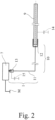
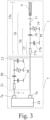
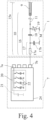
- a particularly advantageous feature is the fact that the input capacitance and thus the connection state can be checked with only a single connection line, since the input capacitance or the input impedance is relative to the reference potential, in this case ground potential.
- the reference circuit is designed such that the reference capacitance of the reference circuit has a substantially identical temperature drift as the input capacitance of the sensor arrangement, so that within the scope of the diagnostic routine, compensation of a possible temperature drift of the input capacitance is possible via the reference circuit.
- the reference circuit 20 can be designed as a reference oscillating circuit (not shown), wherein the sensor arrangement 1 is switched into the reference oscillating circuit by means of the control unit 7 as part of the diagnostic routine.
- the reference oscillating circuit is preferably designed such that a change in the input capacitance 15 is accompanied by a detuning of the reference oscillating circuit. It is preferably provided that a resulting detuning of the reference oscillating circuit is determined by means of the control unit 7 and the connection state of the electrode 9 is deduced from this.
- control unit 7 mentioned above is claimed as such for controlling the capacitive sensor arrangement 1. Reference may be made to all of the above statements regarding the control unit 7.
Landscapes
- Physics & Mathematics (AREA)
- General Physics & Mathematics (AREA)
- Chemical & Material Sciences (AREA)
- Engineering & Computer Science (AREA)
- Combustion & Propulsion (AREA)
- Measurement Of Length, Angles, Or The Like Using Electric Or Magnetic Means (AREA)
- Investigating Or Analyzing Materials By The Use Of Electric Means (AREA)
- Measurement Of Resistance Or Impedance (AREA)
Claims (14)
- Procédé de fonctionnement d'un ensemble de capteurs capacitifs (1) d'un véhicule automobile (2) pour déterminer une distance (3) à un objet de mesure (B), une unité de commande (7) étant prévue pour commander l'ensemble de capteurs (1), l'ensemble de capteurs (1) comportant au moins une électrode (9) et un ensemble de bornes (10) associé à l'électrode (9) et comprenant une ligne de liaison (11) et une borne côté électrode (12) couplée à celle-ci et une borne côté unité de commande (13), dans le cadre d'une routine de mesure l'électrode (9) étant commandée au moyen de l'unité de commande (7) et les valeurs de distance résultantes étant déterminées en fonction d'une capacité de mesure (14) formée par l'électrode (9) par rapport à un potentiel de référence, notamment par rapport au potentiel de masse (M), dans le cadre d'une routine de diagnostic l'état de liaison électrique de l'électrode (9) étant vérifié au moyen de l'unité de commande (7) en ce qui concerne la liaison à l'unité de commande (7),
caractérisé en ce que
dans le cadre de la routine de diagnostic l'état de liaison est vérifié au moyen de l'unité de commande (7) sur la base de la capacité d'entrée (15) entre la borne côté unité de commande (13) et le potentiel de référence et en ce que l'unité de commande (7) comprend un circuit de référence (20), dans le cadre de la routine de diagnostic pour déterminer l'état de liaison de l'électrode (9) au moyen de l'unité de commande (7), le circuit de référence (20) et l'ensemble de capteurs (1) sont commandés avec une tension de diagnostic ou un courant de diagnostic et en ce que l'état de liaison de l'électrode (9) est déduit à partir des courants de mesure résultants ou des tensions de mesure résultantes par comparaison des courants de mesure résultants entre eux ou des tensions de mesure résultantes entre elles et en ce que le circuit de référence (20) fournit une capacité de référence (21), en particulier par rapport au potentiel de référence, qui est sensiblement identique à la capacité d'entrée (15), au moins dans une zone de fonctionnement. - Procédé selon la revendication 1, caractérisé en ce que la capacité d'entrée est la composante capacitive de l'impédance d'entrée (15a) entre la borne côté unité de commande (13) et le potentiel de référence.
- Procédé selon la revendication 1 ou 2, caractérisé en ce que l'ensemble de capteurs (1) comporte, en particulier entre l'unité de commande (7) et l'ensemble de bornes (10) ou dans l'ensemble de bornes (10), au moins un circuit de filtrage (16), de préférence, en ce que le circuit de filtrage (16) comporte un filtre passe-bas (17) et/ou un condensateur de découplage (18) et/ou un élément de protection ESD (19).
- Procédé selon l'une des revendications précédentes, caractérisé en ce que la capacité d'entrée (15) et/ou l'impédance d'entrée (15a) se trouve dans une zone admissible prédéterminée lorsque l'état de liaison cible est non défectueux, en ce que la capacité d'entrée (15) ou l'impédance d'entrée (15a) se trouve à l'extérieur de la zone admissible entre la borne côté unité de commande (13) et le potentiel de référence lorsqu'un état de liaison est défectueux et en ce que l'état de liaison est détecté comme état de liaison défectueux au moyen de l'unité de commande (7) lorsque la capacité d'entrée (15) ou l'impédance d'entrée (15a) se trouve à l'extérieur de la zone admissible.
- Procédé selon la revendication 4, caractérisé en ce que la capacité d'entrée (15) ou l'impédance d'entrée (15a) est déterminée au moyen de l'unité de commande (7) et, pour déterminer l'état de liaison, est comparée à la zone admissible pour la capacité d'entrée (15) ou pour l'impédance d'entrée (15a).
- Procédé selon l'une des revendications précédentes, caractérisé en ce que, dans le cadre de la routine de diagnostic, le circuit de référence (20) et l'ensemble de capteurs (1) sont commandés de manière identique au moyen de l'unité de commande (7), de préférence en ce que cette commande est identique à la commande de l'ensemble de capteurs (1) dans le cadre de la routine de mesure.
- Procédé selon l'une des revendications précédentes, caractérisé en ce que la tension de diagnostic est un saut de tension ou une impulsion de tension ou une tension alternative, ou en ce que le courant de diagnostic est un saut de courant ou une impulsion de courant ou un courant alternatif.
- Procédé selon l'une des revendications précédentes, caractérisé en ce que la capacité de référence (21) du circuit de référence (20) présente une dérive en température sensiblement identique à celle de la capacité d'entrée (15).
- Procédé selon l'une des revendications précédentes, caractérisé en ce que, dans le cadre de la routine de diagnostic, l'état de liaison de l'électrode (9) est déduit au moyen de l'unité de commande (7) à partir de la différence entre la capacité de référence (21) du circuit de référence (20) et la capacité d'entrée (15), notamment d'une différence ou d'un rapport.
- Procédé selon l'une des revendications précédentes, caractérisé en ce que le circuit de référence (20) est un circuit résonant de référence et en ce que, dans le cadre de la routine de diagnostic, l'ensemble de capteurs (1) est commuté au moyen de l'unité de commande (7) dans le circuit résonant de référence, de préférence en ce qu'un désaccord résultant du circuit résonant de référence est déterminé au moyen de l'unité de commande (7) et l'état de liaison de l'électrode (9) est déduit à partir de celui-ci.
- Procédé selon l'une des revendications précédentes, caractérisé en ce que le circuit de référence (20), notamment la capacité de référence (21), peut être paramétré, de préférence en ce que la capacité d'entrée (15) est déterminée dans le cadre d'une routine d'apprentissage et en ce que le circuit de référence (20) est ensuite paramétré.
- Procédé selon l'une des revendications précédentes, caractérisé en ce que l'unité de commande (7) comporte un composant intégré (24) comprenant une unité de calcul destinée à déterminer l'état de liaison de l'électrode (9), de préférence en ce que le circuit de référence (20) est conçu comme un circuit discret séparément du composant intégré (24) ou en ce que le circuit de référence (20) fait partie du composant intégré (24).
- Unité de commande destinée à commander un ensemble de capteurs capacitifs (1) d'un véhicule automobile (2) afin de déterminer une distance (3) à un objet de mesure (B), l'ensemble de capteurs (1) comportant au moins une électrode (9) et un ensemble de bornes (10) associé à l'électrode (9) et comprenant une ligne de liaison (19) et une borne côté électrode (12) couplée à ladite liaison et une borne côté unité de commande (13), dans le cadre d'une routine de mesure l'unité de commande (7) commandant l'électrode (9) et déterminant les valeurs de distance résultantes en fonction d'une capacité de mesure (14) formée par l'électrode (9) par rapport à un potentiel de référence, notamment par rapport au potentiel de masse (M), dans le cadre d'une routine de diagnostic l'unité de commande (7) vérifiant l'état de liaison électrique de l'électrode (9) en ce qui concerne la liaison à l'unité de commande (7),
caractérisée en ce que
dans le cadre de la routine de diagnostic l'unité de commande (7) vérifie l'état de liaison sur la base de la capacité d'entrée (15) entre la borne côté unité de commande (13) et le potentiel de référence et en ce que l'unité de commande (7) comprend un circuit de référence (20), en ce que dans le cadre de la routine de diagnostic le circuit de référence (20) et l'ensemble de capteurs (1) sont commandés avec une tension de diagnostic ou un courant de diagnostic afin de déterminer l'état de liaison de l'électrode (9) au moyen de l'unité de commande (7) et en ce que l'état de liaison de l'électrode (9) est déduit à partir des courants de mesure résultants ou des tensions de mesure résultantes par comparaison des courants de mesure résultants entre eux ou des tensions de mesure résultantes entre elles, et en ce que le circuit de référence (20) fournit une capacité de référence (21), notamment par rapport au potentiel de référence, qui est sensiblement identique à la capacité d'entrée (15), au moins dans une zone de fonctionnement. - Système de capteurs d'un véhicule automobile comprenant au moins un ensemble de capteurs capacitifs (1) destiné à déterminer une distance (3) à un objet de mesure (B) et une unité de commande (7) destinée à commander l'ensemble de capteurs (1), l'ensemble de capteurs (1) comportant au moins une électrode (9) et un ensemble de bornes (10) associé à l'électrode (9) et comprenant une ligne de liaison (11) et une borne côté électrode (12) couplée à ladite ligne de liaison et une borne côté unité de commande (13), dans le cadre d'une routine de mesure l'unité de commande (7) commandant l'électrode (9) et déterminant les valeurs de distance résultantes en fonction d'une capacité de mesure (14) formée par l'électrode (9) par rapport à un potentiel de référence, notamment par rapport au potentiel de masse (M), dans le cadre d'une routine de diagnostic l'unité de commande (7) vérifiant l'état de liaison électrique de l'électrode (9) en ce qui concerne la liaison à l'unité de commande (7),
caractérisé en ce que
dans le cadre de la routine de diagnostic l'unité de commande (7) vérifie l'état de liaison sur la base de la capacité d'entrée (15) entre la borne côté unité de commande (13) et le potentiel de référence et en ce que l'unité de commande (7) comprend un circuit de référence (20), en ce que dans le cadre de la routine de diagnostic le circuit de référence (20) et l'ensemble de capteurs (1) sont commandés avec une tension de diagnostic ou un courant de diagnostic au moyen de l'unité de commande (7) afin de déterminer l'état de liaison de l'électrode (9) et en ce que l'état de liaison de l'électrode (9) est déduit à partir des courants de mesure résultants ou des tensions de mesure résultantes par comparaison des courants de mesure résultants entre eux ou des tensions de mesure résultantes entre elles, et en ce que le circuit de référence (20) fournit une capacité de référence (21), en particulier par rapport au potentiel de référence, qui est sensiblement identique à la capacité d'entrée (15) au moins dans une zone de fonctionnement.
Applications Claiming Priority (1)
| Application Number | Priority Date | Filing Date | Title |
|---|---|---|---|
| DE102015119701.4A DE102015119701A1 (de) | 2015-11-15 | 2015-11-15 | Verfahren für den Betrieb einer kapazitiven Sensoranordnung eines Kraftfahrzeugs |
Publications (3)
| Publication Number | Publication Date |
|---|---|
| EP3171124A1 EP3171124A1 (fr) | 2017-05-24 |
| EP3171124B1 EP3171124B1 (fr) | 2018-06-27 |
| EP3171124B2 true EP3171124B2 (fr) | 2024-07-03 |
Family
ID=57288143
Family Applications (1)
| Application Number | Title | Priority Date | Filing Date |
|---|---|---|---|
| EP16195945.7A Not-in-force EP3171124B2 (fr) | 2015-11-15 | 2016-10-27 | Procédé de fonctionnement d'un système de détection capacitif d'un véhicule automobile |
Country Status (5)
| Country | Link |
|---|---|
| US (1) | US10429430B2 (fr) |
| EP (1) | EP3171124B2 (fr) |
| KR (1) | KR102668015B1 (fr) |
| CN (1) | CN107064721B (fr) |
| DE (1) | DE102015119701A1 (fr) |
Families Citing this family (13)
| Publication number | Priority date | Publication date | Assignee | Title |
|---|---|---|---|---|
| DE102011121775B3 (de) | 2011-12-21 | 2013-01-31 | Brose Fahrzeugteile Gmbh & Co. Kg, Hallstadt | Steuersystem |
| DE102012107115A1 (de) * | 2012-08-02 | 2014-02-06 | Brose Fahrzeugteile Gmbh & Co. Kommanditgesellschaft, Hallstadt | Verfahren zur Steuerung eines kapazitiven Einklemmschutzsystems und Einklemmschutzsystem |
| DE102015119701A1 (de) * | 2015-11-15 | 2017-05-18 | Brose Fahrzeugteile Gmbh & Co. Kommanditgesellschaft, Bamberg | Verfahren für den Betrieb einer kapazitiven Sensoranordnung eines Kraftfahrzeugs |
| US10380817B2 (en) * | 2016-11-28 | 2019-08-13 | Honda Motor Co., Ltd. | System and method for providing hands free operation of at least one vehicle door |
| US10815717B2 (en) | 2016-11-28 | 2020-10-27 | Honda Motor Co., Ltd. | System and method for providing hands free operation of at least one vehicle door |
| KR102354135B1 (ko) * | 2017-10-12 | 2022-01-24 | 현대자동차주식회사 | 근접센서 |
| DE102017220540B4 (de) * | 2017-11-17 | 2024-04-25 | Ge-T Gmbh | Bauelement und Verfahren zur Belegungserkennung eines Bauelements |
| CN108331484B (zh) * | 2018-01-05 | 2019-12-27 | 上海纳恩汽车技术有限公司 | 一种汽车尾门脚踢传感器系统 |
| JP7482599B2 (ja) * | 2018-10-24 | 2024-05-14 | ローム株式会社 | ドライバ回路 |
| DE102018220145A1 (de) | 2018-11-23 | 2020-05-28 | Brose Fahrzeugteile Se & Co. Kommanditgesellschaft, Bamberg | Verfahren und Verstellvorrichtung zum Verstellen eines Fahrzeugverstellteils mit ausgegebener Statusinformation |
| KR20200073297A (ko) * | 2018-11-30 | 2020-06-24 | 현대자동차주식회사 | 대향형 슬라이딩 도어의 휠 간섭 방지 시스템 및 그 방법 |
| DE102019114254A1 (de) * | 2019-05-28 | 2020-12-03 | Huf Hülsbeck & Fürst Gmbh & Co. Kg | Anordnung zur Verbindungsprüfung bei einer kapazitiven Sensoranordnung eines Fahrzeuges |
| US11847833B2 (en) | 2020-02-12 | 2023-12-19 | Strattec Security Corporation | Broad coverage non-contact obstacle detection |
Citations (6)
| Publication number | Priority date | Publication date | Assignee | Title |
|---|---|---|---|---|
| DE60115320T2 (de) † | 2000-05-12 | 2006-08-17 | Dr. Anthony Oxnard Bledin | Einklemmschutz |
| DE102006051750A1 (de) † | 2005-11-09 | 2007-05-16 | Denso Corp | Fahrzeugkollisionserfassungsvorrichtung |
| DE102008044067A1 (de) † | 2008-11-25 | 2010-05-27 | Huf Hülsbeck & Fürst Gmbh & Co. Kg | Kapazitiver Annäherungssensor mit einer Schirmelektrode und einer Diagnoseelektrode |
| DE102011004288A1 (de) † | 2011-02-17 | 2012-08-23 | Robert Bosch Gmbh | Anordnung und Verfahren zur Verbindungsabrisserkennung an einem Schaltungsteil mit kapazitivem Verhalten |
| US20130207677A1 (en) † | 2010-09-28 | 2013-08-15 | Fujikura, Ltd. | Electrostatic capacitance sensor and method for determining failure of electrostatic capacitance sensor |
| DE112014000714T5 (de) † | 2013-02-07 | 2015-10-29 | Iee International Electronics & Engineering S.A. | Kapazitiver Sensor |
Family Cites Families (120)
| Publication number | Priority date | Publication date | Assignee | Title |
|---|---|---|---|---|
| US2127359A (en) | 1936-11-24 | 1938-08-16 | Bertron G Harley | Coupling |
| DE1951137B2 (de) * | 1969-10-10 | 1973-03-01 | lfm electronic gerate GmbH & Co KG, 4300 Essen | Elektronisches, beruehrungslos arbeitendes schaltgeraet |
| US4495330A (en) | 1983-05-25 | 1985-01-22 | General Electric Company | Crosslinkers for RTV compositions |
| US4867059A (en) | 1988-08-05 | 1989-09-19 | International Business Machines Corporation | Impact printer print mechanism and method of manufacture |
| US5489888A (en) * | 1990-11-07 | 1996-02-06 | Precitec Gmbh | Sensor system for contactless distance measuring |
| US5394292A (en) * | 1991-04-30 | 1995-02-28 | Tsuden Kabushiki Kaisha | Electronic car bumper |
| DE4133426A1 (de) * | 1991-10-09 | 1993-04-15 | Bosch Gmbh Robert | Schaltungsanordnung zur auswertung und zum test eines kapazitiven sensors |
| DE4201640C1 (en) * | 1992-01-22 | 1993-02-25 | Weidmueller Interface Gmbh & Co, 4930 Detmold, De | Nozzle for processing workpiece e.g. by laser beam - consists of nozzle body with sensor element of e.g. copper@ attached to insulating body for contactless measurement |
| DE4408468A1 (de) * | 1994-03-12 | 1995-09-14 | Turck Werner Kg | Verfahren und Vorrichtung zur Individualisierung von galvanisch getrennten elektrisch leitfähigen Körpern |
| GB2295016A (en) * | 1994-11-07 | 1996-05-15 | British Nuclear Fuels Plc | A transducer |
| DE9421122U1 (de) | 1994-11-10 | 1995-04-27 | Horst Siedle Kg, 78120 Furtwangen | Vorrichtung zur Bestimmung einer jeweiligen örtlichen Position eines Körpers |
| FR2740501B1 (fr) | 1995-10-26 | 1998-06-19 | Valeo Securite Habitacle | Systeme mains libres de deverrouillage et/ou d'ouverture d'ouvrant de vehicule automobile |
| US5844486A (en) | 1997-01-02 | 1998-12-01 | Advanced Safety Concepts, Inc. | Integral capacitive sensor array |
| US6275146B1 (en) | 1996-04-23 | 2001-08-14 | Philip W. Kithil | Vehicle occupant sensing |
| AU2741297A (en) | 1996-04-23 | 1997-11-12 | Advanced Safety Concepts, Inc. | Vehicle occupant sensing |
| GB9712848D0 (en) * | 1997-06-18 | 1997-08-20 | Queensgate Instr Ltd | Capacitance micrometer |
| DE59803939D1 (de) * | 1997-11-28 | 2002-05-29 | Iee Sarl | Kapazitive distanzmessung mit einer nicht idealen messelektrode |
| US6535200B2 (en) | 1999-01-25 | 2003-03-18 | Harald Philipp | Capacitive position sensor |
| JP3754285B2 (ja) | 2000-09-27 | 2006-03-08 | 株式会社大井製作所 | ドアの自動開閉装置 |
| US6411054B1 (en) | 2000-12-15 | 2002-06-25 | Ford Global Technologies, Inc. | Obstruction detection system for power liftgate |
| US6748308B2 (en) | 2001-03-30 | 2004-06-08 | Siemens Vdo Automotive Corporation | Automated closure system and method |
| GB2376075A (en) | 2001-06-01 | 2002-12-04 | Ab Automotive Electronics Ltd | Bumper proximity detector using capacitive sensor |
| CA2451010C (fr) | 2001-06-08 | 2012-01-03 | Intier Automotive Closures Inc. | Capteur de proximite sans contact |
| US8225458B1 (en) | 2001-07-13 | 2012-07-24 | Hoffberg Steven M | Intelligent door restraint |
| DE10235925A1 (de) | 2002-08-06 | 2004-02-19 | Valeo Schalter Und Sensoren Gmbh | Fahrzeugumfeldüberwachungssystem und automatische Fahrzeugtüröffnungseinrichtung |
| US6774642B2 (en) | 2002-08-27 | 2004-08-10 | Delphi Technologies, Inc. | Capacitive angular position sensor |
| DE10254708A1 (de) | 2002-11-23 | 2004-06-03 | Adam Opel Ag | Verfahren zum fernbetätigten Öffnen bzw. Schließen einer heckseitigen Klappe eines Kraftfahrzeuges und Vorrichtung dazu |
| US20050114276A1 (en) | 2003-11-20 | 2005-05-26 | Hunter Valerie K. | Personal customization of stamps |
| DE102004008928A1 (de) | 2004-02-24 | 2005-09-08 | Bayerische Motoren Werke Ag | Verfahren zum Ankuppeln eines Anhängers unter Einsatz einer Fahrzeugniveauregulierung |
| FR2866612B1 (fr) | 2004-02-25 | 2006-05-05 | Renault Sas | Vehicule comportant un porte-charge |
| FR2868526B1 (fr) | 2004-04-06 | 2007-04-20 | Peugeot Citroen Automobiles Sa | Capteur de position d'un actionneur de soupape d'un moteur a combustion interne |
| JP4610300B2 (ja) | 2004-11-02 | 2011-01-12 | 富士通テン株式会社 | 車両用制御装置および車両用制御方法 |
| DE102004055982A1 (de) | 2004-11-19 | 2006-06-01 | Daimlerchrysler Ag | Schließsystem für ein Fahrzeug |
| DE102004057220B4 (de) | 2004-11-26 | 2011-07-21 | Audi Ag, 85057 | Verfahren und Vorrichtung zum Unterscheiden eines Anhängers von einer Trägereinrichtung am Heck eines Fahrzeugs |
| DE102005002046B4 (de) | 2005-01-14 | 2009-02-05 | Dorma Gmbh + Co. Kg | Schiebetür mit einem magnetischen Antriebssystem mit einem Wegmesssystem |
| US7354097B2 (en) | 2005-05-25 | 2008-04-08 | Gm Global Technology Operations, Inc. | Power-actuated closure system |
| DE102005032402B3 (de) | 2005-07-12 | 2006-09-28 | Daimlerchrysler Ag | Verfahren zum Nachweis einer Berechtigung zum Ver- oder Entriegeln eines Objekts sowie Sicherheitsvorrichtung |
| DE102005042402A1 (de) | 2005-09-06 | 2007-03-08 | Bayerische Motoren Werke Ag | Kraftfahrzeug mit automatisch öffnender Klappe |
| US8179435B2 (en) | 2005-09-28 | 2012-05-15 | Nissan Motor Co., Ltd. | Vehicle surroundings image providing system and method |
| US7217891B2 (en) * | 2005-09-29 | 2007-05-15 | Delphi Technologies, Inc. | Capacitive sensing apparatus for a vehicle seat |
| DE102005055002B4 (de) | 2005-11-18 | 2024-05-16 | Bayerische Motoren Werke Aktiengesellschaft | Kraftfahrzeug mit automatisch öffnender beziehungsweise schließender Klappe |
| DE202005020140U1 (de) | 2005-12-22 | 2007-05-10 | BROSE SCHLIEßSYSTEME GMBH & CO. KG | Kraftfahrzeugtüranordnung |
| JP2007228640A (ja) | 2006-02-21 | 2007-09-06 | Combi Corp | 揺動装置 |
| US7688013B2 (en) * | 2006-06-21 | 2010-03-30 | Flextronics Automotive Inc. | System and method for controlling speed of a closure member |
| DE102006030986B4 (de) | 2006-07-03 | 2012-01-19 | Edscha Engineering Gmbh | Vorrichtung und Verfahren zur Steuerung einer Fahrzeugklappe oder einer Fahrzeugtür |
| DE102007000713A1 (de) * | 2006-09-08 | 2008-04-10 | Aisin Seiki K.K., Kariya | Kapazitätserfassungsgerät |
| DE102006044112A1 (de) | 2006-09-20 | 2008-03-27 | Hella Kgaa Hueck & Co. | Kraftfahrzeug mit einer Sensoranordnung |
| DE102007047887A1 (de) * | 2006-11-29 | 2008-06-19 | Aisin Seiki Kabushiki Kaisha, Kariya | Kapazitätserfassungsvorrichtung |
| JP2008203055A (ja) * | 2007-02-20 | 2008-09-04 | Omron Corp | 静電容量センサ |
| JP2008238992A (ja) | 2007-03-28 | 2008-10-09 | Honda Motor Co Ltd | 静電容量型センサの取付け構造およびその組付け方法 |
| FR2917771B1 (fr) | 2007-06-25 | 2009-09-04 | Valeo Securite Habitacle Sas | Procede securise de fermeture automatique d'un hayon de vehicule automobile |
| DE102007035904B4 (de) | 2007-07-31 | 2009-09-17 | Continental Automotive Gmbh | Benutzeridentifizierungsvorrichtung |
| CA2698509C (fr) | 2007-08-30 | 2013-06-11 | Flextronics Automotive Inc. | Systeme et procede de freinage dynamique d'un systeme de fermeture de vehicule |
| JP5309515B2 (ja) | 2007-09-25 | 2013-10-09 | アイシン精機株式会社 | 車両用ドア開閉制御装置 |
| GB0718677D0 (en) | 2007-09-25 | 2007-10-31 | 3M Innovative Properties Co | Capacitive sensor and proximity detector using it |
| EP2187241B1 (fr) * | 2007-10-04 | 2018-09-19 | Fujikura Ltd. | Capteur de proximité capacitif et procédé de détection de proximité |
| JP2009133777A (ja) * | 2007-11-30 | 2009-06-18 | Toyota Motor Corp | 静電容量式接触検知装置 |
| US7880481B2 (en) | 2007-12-19 | 2011-02-01 | Infineon Technologies Ag | Capacitive sensor and measurement system |
| JP2009175045A (ja) | 2008-01-25 | 2009-08-06 | Denso Corp | 周辺監視装置 |
| JP5177510B2 (ja) | 2008-03-27 | 2013-04-03 | アイシン精機株式会社 | 超音波センサ |
| DE202009018206U1 (de) | 2008-04-29 | 2011-05-05 | Volkswagen Ag | Vorrichtung zur Betätigung einer Tür oder Klappe eines Fahrzeugs |
| WO2009150618A2 (fr) | 2008-06-13 | 2009-12-17 | Koninklijke Philips Electronics N.V. | Capteur de proximité capacitif et dispositif électronique comprenant le capteur de proximité capacitif |
| DE102008035627A1 (de) * | 2008-07-31 | 2010-02-11 | Gerd Reime | Vorrichtung zur kapazitiven Messung von Änderungen |
| DE102008041354A1 (de) | 2008-08-19 | 2010-02-25 | Robert Bosch Gmbh | Verfahren und Vorrichtung zum automatischen Öffnen einer Fahrzeugtüre oder dergleichen |
| US8058993B2 (en) | 2008-09-30 | 2011-11-15 | Infineon Technologies Ag | Capacitive detection systems and methods |
| EP2362178A1 (fr) * | 2008-10-31 | 2011-08-31 | Fujikura Ltd. | Capteur de type capacitif |
| DE102008063366B4 (de) | 2008-12-30 | 2022-04-28 | Huf Hülsbeck & Fürst Gmbh & Co. Kg | Einrichtung zum berührungslosen Betätigen einer Heckklappe eines Kraftfahrzeugs sowie Verfahren zum Betätigen einer Heckklappe eines Kraftfahrzeuges und Kraftfahrzeug |
| FR2943190B1 (fr) | 2009-03-13 | 2016-12-30 | Valeo Securite Habitacle | Dispositif de declenchement d'une action sur un ouvrant de vehicule automobile |
| JP5569712B2 (ja) | 2009-03-30 | 2014-08-13 | アイシン精機株式会社 | ドア制御装置 |
| US9051769B2 (en) | 2009-08-21 | 2015-06-09 | Uusi, Llc | Vehicle assembly having a capacitive sensor |
| US9845629B2 (en) | 2009-08-21 | 2017-12-19 | Uusi, Llc | Vehicle keyless entry assembly having capacitance sensor operative for detecting objects |
| DE102009041555A1 (de) | 2009-09-15 | 2010-06-17 | Daimler Ag | Verfahren und Vorrichtung zum Warnen eines Fahrzeugführers vor einem Objekt |
| DE102009047066A1 (de) | 2009-11-24 | 2011-05-26 | Robert Bosch Gmbh | Verfahren zur Warnung vor einem Objekt in der Umgebung eines Fahrzeugs sowie Fahrassistentensystem |
| DE102009055778B4 (de) | 2009-11-25 | 2021-05-27 | Audi Ag | Verfahren zum Betreiben eines Mechanismus zum Öffnen einer Heckklappe sowie Kraftfahrzeug mit einer Heckklappe |
| DE102009055426A1 (de) * | 2009-12-30 | 2011-07-07 | Takata-Petri Ag, 63743 | Kapazitive Sensorbaugruppe |
| DE102010006213A1 (de) | 2010-01-29 | 2011-08-04 | Bayerische Motoren Werke Aktiengesellschaft, 80809 | Steuervorrichtung für ein Fahrzeug mit automatisch öffnender und/oder automatisch schließender Klappe |
| DE102010002559B4 (de) | 2010-03-03 | 2025-08-14 | Huf Hülsbeck & Fürst Gmbh & Co. Kg | Kapazitive Sensorvorrichtung zur Schaltung einer Türöffnung an einem Kraftfahrzeug und Stoßfänger damit |
| DE102010045008B4 (de) * | 2010-09-10 | 2013-02-28 | Brose Fahrzeugteile Gmbh & Co. Kommanditgesellschaft, Hallstadt | Kapazitiver Abstandssensor |
| DE102010037577B4 (de) | 2010-09-16 | 2025-07-17 | Huf Hülsbeck & Fürst Gmbh & Co. Kg | Erfassungsverfahren für Betätigungsgesten und zugehöriges Kalibrierungsverfahren |
| DE102010048144A1 (de) | 2010-10-11 | 2011-07-28 | Daimler AG, 70327 | Kraftfahrzeug mit einer Überwachungseinrichtung zur Überwachung des Umgebungsbereichs des Fahrzeugs |
| WO2012052210A1 (fr) | 2010-10-22 | 2012-04-26 | Huf Hülsbeck & Fürst Gmbh & Co. Kg | Système de capteur capacitif pour déclencher une ouverture de porte sur un véhicule automobile |
| DE102010049400A1 (de) | 2010-10-26 | 2012-04-26 | Brose Fahrzeugteile Gmbh & Co. Kommanditgesellschaft, Hallstadt | Sensoreinheit zum berührungslosen Betätigen einer Fahrzeugtür |
| DE102010055297A1 (de) | 2010-12-21 | 2012-06-21 | Brose Fahrzeugteile Gmbh & Co. Kommanditgesellschaft, Hallstadt | Verfahren zur Erzeugung einer Bedienmeldung beim Auftreten eines Bedienereignisses |
| US9081409B2 (en) | 2011-01-21 | 2015-07-14 | The United States Of America As Represented By The Secretary Of The Navy | Event detection control system for operating a remote sensor or projectile system |
| DE102011010620B4 (de) * | 2011-02-08 | 2014-07-17 | Brose Fahrzeugteile Gmbh & Co. Kommanditgesellschaft, Hallstadt | Verfahren zum Messen einer Kapazität |
| DE102011018847A1 (de) | 2011-04-27 | 2012-10-31 | Brose Fahrzeugteile Gmbh & Co. Kommanditgesellschaft, Hallstadt | Verfahren zur Ansteuerung einer Verschlusselementanordnung eines Kraftfahrzeugs |
| DE102011051434A1 (de) | 2011-06-29 | 2013-01-03 | Huf Hülsbeck & Fürst Gmbh & Co. Kg | Kapazitive Sensoranordnung und Verfahren zur Erfassung von Betätigungsgesten an einem Kraftfahrzeug |
| DE102011111209A1 (de) * | 2011-08-20 | 2013-02-21 | Brose Fahrzeugteile Gmbh & Co. Kommanditgesellschaft, Hallstadt | Türmodul mit integrierter Sensorelektrode |
| DE102011112274A1 (de) | 2011-09-05 | 2013-03-07 | Brose Fahrzeugteile Gmbh & Co. Kg, Hallstadt | Steuersystem |
| DE102011121775B3 (de) | 2011-12-21 | 2013-01-31 | Brose Fahrzeugteile Gmbh & Co. Kg, Hallstadt | Steuersystem |
| US9791494B2 (en) * | 2012-01-20 | 2017-10-17 | Lear Corporation | Apparatus and method for diagnostics of a capacitive sensor |
| DE102012008530A1 (de) | 2012-05-02 | 2013-11-07 | Brose Fahrzeugteile Gmbh & Co. Kg, Hallstadt | Verfahren zur Ansteuerung einer Verschlusselementanordnung eines Kraftfahrzeugs |
| DE102012104915A1 (de) | 2012-06-06 | 2013-12-12 | Huf Hülsbeck & Fürst Gmbh & Co. Kg | Kapazitive Sensoranordnung zur Schaltung einer Türöffnung an einem Kraftfahrzeug |
| DE102012013065A1 (de) | 2012-07-02 | 2014-01-02 | Brose Fahrzeugteile Gmbh & Co. Kg, Hallstadt | Verfahren zur Ansteuerung einer Verschlusselementanordnung eines Kraftfahrzeugs |
| DE102012014676A1 (de) | 2012-07-25 | 2014-01-30 | Brose Fahrzeugteile Gmbh & Co. Kg, Hallstadt | Verfahren zur Ansteuerung einer Verschlusselementanordnung insbesondere eines Kraftfahrzeugs |
| US9488460B2 (en) * | 2012-07-30 | 2016-11-08 | Continental Automotive Gmbh | Capacitive sensing node integration to a surface of a mechanical part |
| DE102012107116A1 (de) * | 2012-08-02 | 2014-02-06 | Brose Fahrzeugteile Gmbh & Co. Kommanditgesellschaft, Hallstadt | Verfahren zur Steuerung einer Verstellbewegung eines Fahrzeugschließelements mit Kollisionsvermeidung für einen Schlossbereich und Einklemmschutzsystem |
| DE102013001066B4 (de) * | 2013-01-23 | 2022-01-20 | Brose Fahrzeugteile Se & Co. Kommanditgesellschaft, Bamberg | Kapazitiver Näherungssensor |
| DE102013010993B4 (de) | 2013-07-02 | 2026-08-20 | Brose Fahrzeugteile Gmbh & Co. Kommanditgesellschaft, Bamberg | Objekterfassungsvorrichtung für ein Fahrzeug |
| DE102013110506A1 (de) * | 2013-07-03 | 2015-01-08 | Huf Hülsbeck & Fürst Gmbh & Co. Kg | Erfassungsverfahren für Betätigungsgesten |
| JP6018547B2 (ja) | 2013-07-09 | 2016-11-02 | 大成ロテック株式会社 | 舗装機械 |
| JP2015031552A (ja) * | 2013-08-01 | 2015-02-16 | アイシン精機株式会社 | 静電容量センサ |
| DE102013014824A1 (de) * | 2013-09-10 | 2015-03-12 | Brose Fahrzeugteile Gmbh & Co. Kommanditgesellschaft, Hallstadt | Kapazitiver Sensor für ein Fahrzeug |
| DE102013018593B4 (de) | 2013-11-07 | 2022-04-21 | Brose Fahrzeugteile Se & Co. Kommanditgesellschaft, Bamberg | Verfahren zur Ansteuerung einer Verschlusselementanordnung eines Kraftfahrzeugs |
| DE102013112418A1 (de) | 2013-11-12 | 2015-05-13 | Brose Fahrzeugteile Gmbh & Co. Kommanditgesellschaft, Hallstadt | Kapazitive Sensoranordnung eines Kraftfahrzeugs |
| DE102013022102A1 (de) * | 2013-12-23 | 2015-06-25 | Brose Fahrzeugteile Gmbh & Co. Kommanditgesellschaft, Hallstadt | Stellverfahren und Stellvorrichtung für ein Fahrzeugteil |
| DE102013114883A1 (de) | 2013-12-25 | 2015-06-25 | Brose Fahrzeugteile Gmbh & Co. Kommanditgesellschaft, Hallstadt | Steuersystem für eine motorische Verschlusselementanordnung eines Kraftfahrzeugs |
| DE102013114881A1 (de) | 2013-12-25 | 2015-06-25 | Brose Fahrzeugteile Gmbh & Co. Kommanditgesellschaft, Hallstadt | Steuersystem für eine motorische Verschlusselementanordnung eines Kraftfahrzeugs |
| EP2905901B1 (fr) * | 2014-02-06 | 2019-12-18 | Brose Fahrzeugteile GmbH & Co. Kommanditgesellschaft, Bamberg | Procédé et dispositif de détermination d'une capacité et/ou d'une modification de capacité d'un élément de construction capacitif |
| JP5826310B2 (ja) | 2014-02-20 | 2015-12-02 | 富士重工業株式会社 | 開閉制御機能を備える車両 |
| US9399389B2 (en) | 2014-03-17 | 2016-07-26 | Fca Us Llc | Reduced offset lift-gate applique |
| DE102014007651A1 (de) * | 2014-05-23 | 2015-11-26 | Brose Fahrzeugteile Gmbh & Co. Kommanditgesellschaft, Hallstadt | Fahrzeugteil für den Außenbereich eines Kraftfahrzeugs und Kraftfahrzeug |
| DE102014011703A1 (de) * | 2014-08-07 | 2016-02-11 | Brose Fahrzeugteile Gmbh & Co. Kommanditgesellschaft, Hallstadt | Elektronische Baueinheit, insbesondere kapazitiver Näherungssensor |
| DE102014012652A1 (de) * | 2014-08-21 | 2016-02-25 | Brose Fahrzeugteile Gmbh & Co. Kommanditgesellschaft, Hallstadt | Elektronische Baueinheit, insbesondere kapazitiver Näherungssensor für ein Fahrzeug |
| WO2016046888A1 (fr) * | 2014-09-22 | 2016-03-31 | 三菱電機株式会社 | Dispositif d'entrée et procédé de commande associé |
| FR3028061B1 (fr) * | 2014-10-29 | 2016-12-30 | Fogale Nanotech | Dispositif capteur capacitif comprenant des electrodes ajourees |
| DE102015002128A1 (de) * | 2015-02-19 | 2016-08-25 | Brose Fahrzeugteile Gmbh & Co. Kommanditgesellschaft, Hallstadt | Kapazitiver Näherungssensor für ein Kraftfahrzeug, Kollisionsschutzeinrichtung für ein Kraftfahrzeug und Kraftfahrzeug mit einem kapazitiven Näherungssensor |
| JP6338287B2 (ja) | 2015-03-09 | 2018-06-06 | オムロンオートモーティブエレクトロニクス株式会社 | 車両ドア開閉制御装置 |
| DE102015119701A1 (de) * | 2015-11-15 | 2017-05-18 | Brose Fahrzeugteile Gmbh & Co. Kommanditgesellschaft, Bamberg | Verfahren für den Betrieb einer kapazitiven Sensoranordnung eines Kraftfahrzeugs |
| JP6711009B2 (ja) * | 2016-02-24 | 2020-06-17 | アイシン精機株式会社 | 車両用操作検出装置 |
-
2015
- 2015-11-15 DE DE102015119701.4A patent/DE102015119701A1/de not_active Withdrawn
-
2016
- 2016-10-27 EP EP16195945.7A patent/EP3171124B2/fr not_active Not-in-force
- 2016-11-10 KR KR1020160149366A patent/KR102668015B1/ko active Active
- 2016-11-10 CN CN201610988401.1A patent/CN107064721B/zh active Active
- 2016-11-15 US US15/351,913 patent/US10429430B2/en active Active
Patent Citations (6)
| Publication number | Priority date | Publication date | Assignee | Title |
|---|---|---|---|---|
| DE60115320T2 (de) † | 2000-05-12 | 2006-08-17 | Dr. Anthony Oxnard Bledin | Einklemmschutz |
| DE102006051750A1 (de) † | 2005-11-09 | 2007-05-16 | Denso Corp | Fahrzeugkollisionserfassungsvorrichtung |
| DE102008044067A1 (de) † | 2008-11-25 | 2010-05-27 | Huf Hülsbeck & Fürst Gmbh & Co. Kg | Kapazitiver Annäherungssensor mit einer Schirmelektrode und einer Diagnoseelektrode |
| US20130207677A1 (en) † | 2010-09-28 | 2013-08-15 | Fujikura, Ltd. | Electrostatic capacitance sensor and method for determining failure of electrostatic capacitance sensor |
| DE102011004288A1 (de) † | 2011-02-17 | 2012-08-23 | Robert Bosch Gmbh | Anordnung und Verfahren zur Verbindungsabrisserkennung an einem Schaltungsteil mit kapazitivem Verhalten |
| DE112014000714T5 (de) † | 2013-02-07 | 2015-10-29 | Iee International Electronics & Engineering S.A. | Kapazitiver Sensor |
Also Published As
| Publication number | Publication date |
|---|---|
| CN107064721B (zh) | 2020-12-15 |
| EP3171124A1 (fr) | 2017-05-24 |
| KR102668015B1 (ko) | 2024-05-21 |
| CN107064721A (zh) | 2017-08-18 |
| US10429430B2 (en) | 2019-10-01 |
| KR20170057142A (ko) | 2017-05-24 |
| US20170138997A1 (en) | 2017-05-18 |
| DE102015119701A1 (de) | 2017-05-18 |
| EP3171124B1 (fr) | 2018-06-27 |
Similar Documents
| Publication | Publication Date | Title |
|---|---|---|
| EP3171124B1 (fr) | Procédé de fonctionnement d'un système de détection capacitif d'un véhicule automobile | |
| EP3637114B1 (fr) | Système de haut voltage et procédé de surveillance des erreurs d'isolation dans un système de haut voltage | |
| DE102011005551B4 (de) | Belegungserkennungsvorrichtung zum Erkennen einer Belegung eines Sitzplatzes eines Kraftfahrzeuges | |
| EP3329597B1 (fr) | Dispositif de commande d'un véhicule et procédé de fonctionnement d'un tel dispositif de commande | |
| DE102012202847A1 (de) | Verfahren zur Diagnose der elektrischen Kontaktierung eines Abgassensors | |
| DE102012105266B4 (de) | Kapazitiver Annäherungssensor für ein Kraftfahrzeug | |
| EP2371062A1 (fr) | Capteur de proximité capacitif avec une électrode écran et une électrode de diagnostic | |
| EP4335033A1 (fr) | Ensemble circuit diagnostiquable, appareil capteur doté d'un ensemble circuit et procédé de diagnostic d'un ensemble circuit et/ou appareil capteur | |
| DE112019000888T5 (de) | System zur Erdung und Diagnose | |
| DE102019132508A1 (de) | Kapazitive Sensoreinrichtung sowie Verfahren zur Erkennung einer Objektannäherung | |
| DE112018000220T5 (de) | Elektronische Steuervorrichtung und Anomalie/Normalzustands-Bestimmungsverfahren einer elektronischen Steuervorrichtung | |
| DE102010043744A1 (de) | Schaltungsanordnung sowie Verfahren zur Überwachung des Schaltens einer Energiequelle zur Versorgung eines Elektroantriebs | |
| DE10037495B4 (de) | Verfahren und Vorrichtung zum Erkennen einer Fehlfunktion eines Sensors oder eines Leitungsbruchs | |
| DE102017213540A1 (de) | Kapazitiver Näherungssensor und Verfahren zum Betrieb eines solchen | |
| DE102013112418A1 (de) | Kapazitive Sensoranordnung eines Kraftfahrzeugs | |
| EP3446134B1 (fr) | Détermination de la mise en contact électrique d'un système électrique avec un système de mesure | |
| DE102021111734A1 (de) | Diagnosefähige Schaltungsanordnung und Verfahren zur Diagnose einer Schaltungsanordnung | |
| EP3472935B1 (fr) | Dispositif de détection capacitive à tolérance d'interference améliorée | |
| DE102024110428A1 (de) | Überwachung von elektrischem Masseversatz in einem Fahrzeug | |
| DE102016204806A1 (de) | Schaltungsanordnung zum Erkennen eines Schaltungszustands an einem Schaltungspunkt | |
| DE102023203477B4 (de) | Belegungserfassungseinrichtung und Verfahren zum Erfassen des Belegungszustands einer Fahrzeugkomponente sowie Lenkrad und Fahrzeugsitz mit einem Messmodul einer solchen Belegungserfassungseinrichtung | |
| DE102017210871A1 (de) | Ansteuerung eines elektrischen Verbrauchers | |
| DE102013112815A1 (de) | Sicherheitssteuerung | |
| DE102022131313A1 (de) | Sensorvorrichtung und Verfahren zur kapazitiven Berührungsdetektion | |
| DE102017209096A1 (de) | Auswerteschaltung für einen kapazitive Beschleunigungssensor und Vorrichtung zur Detektion einer Beschleunigung |
Legal Events
| Date | Code | Title | Description |
|---|---|---|---|
| PUAI | Public reference made under article 153(3) epc to a published international application that has entered the european phase |
Free format text: ORIGINAL CODE: 0009012 |
|
| STAA | Information on the status of an ep patent application or granted ep patent |
Free format text: STATUS: THE APPLICATION HAS BEEN PUBLISHED |
|
| AK | Designated contracting states |
Kind code of ref document: A1 Designated state(s): AL AT BE BG CH CY CZ DE DK EE ES FI FR GB GR HR HU IE IS IT LI LT LU LV MC MK MT NL NO PL PT RO RS SE SI SK SM TR |
|
| AX | Request for extension of the european patent |
Extension state: BA ME |
|
| STAA | Information on the status of an ep patent application or granted ep patent |
Free format text: STATUS: REQUEST FOR EXAMINATION WAS MADE |
|
| 17P | Request for examination filed |
Effective date: 20171124 |
|
| RBV | Designated contracting states (corrected) |
Designated state(s): AL AT BE BG CH CY CZ DE DK EE ES FI FR GB GR HR HU IE IS IT LI LT LU LV MC MK MT NL NO PL PT RO RS SE SI SK SM TR |
|
| GRAP | Despatch of communication of intention to grant a patent |
Free format text: ORIGINAL CODE: EPIDOSNIGR1 |
|
| STAA | Information on the status of an ep patent application or granted ep patent |
Free format text: STATUS: GRANT OF PATENT IS INTENDED |
|
| INTG | Intention to grant announced |
Effective date: 20180221 |
|
| GRAS | Grant fee paid |
Free format text: ORIGINAL CODE: EPIDOSNIGR3 |
|
| GRAA | (expected) grant |
Free format text: ORIGINAL CODE: 0009210 |
|
| STAA | Information on the status of an ep patent application or granted ep patent |
Free format text: STATUS: THE PATENT HAS BEEN GRANTED |
|
| AK | Designated contracting states |
Kind code of ref document: B1 Designated state(s): AL AT BE BG CH CY CZ DE DK EE ES FI FR GB GR HR HU IE IS IT LI LT LU LV MC MK MT NL NO PL PT RO RS SE SI SK SM TR |
|
| REG | Reference to a national code |
Ref country code: GB Ref legal event code: FG4D Free format text: NOT ENGLISH |
|
| REG | Reference to a national code |
Ref country code: AT Ref legal event code: REF Ref document number: 1012715 Country of ref document: AT Kind code of ref document: T Effective date: 20180715 |
|
| REG | Reference to a national code |
Ref country code: IE Ref legal event code: FG4D Free format text: LANGUAGE OF EP DOCUMENT: GERMAN |
|
| REG | Reference to a national code |
Ref country code: DE Ref legal event code: R096 Ref document number: 502016001343 Country of ref document: DE |
|
| REG | Reference to a national code |
Ref country code: FR Ref legal event code: PLFP Year of fee payment: 3 |
|
| PG25 | Lapsed in a contracting state [announced via postgrant information from national office to epo] |
Ref country code: SE Free format text: LAPSE BECAUSE OF FAILURE TO SUBMIT A TRANSLATION OF THE DESCRIPTION OR TO PAY THE FEE WITHIN THE PRESCRIBED TIME-LIMIT Effective date: 20180627 Ref country code: FI Free format text: LAPSE BECAUSE OF FAILURE TO SUBMIT A TRANSLATION OF THE DESCRIPTION OR TO PAY THE FEE WITHIN THE PRESCRIBED TIME-LIMIT Effective date: 20180627 Ref country code: BG Free format text: LAPSE BECAUSE OF FAILURE TO SUBMIT A TRANSLATION OF THE DESCRIPTION OR TO PAY THE FEE WITHIN THE PRESCRIBED TIME-LIMIT Effective date: 20180927 Ref country code: NO Free format text: LAPSE BECAUSE OF FAILURE TO SUBMIT A TRANSLATION OF THE DESCRIPTION OR TO PAY THE FEE WITHIN THE PRESCRIBED TIME-LIMIT Effective date: 20180927 Ref country code: LT Free format text: LAPSE BECAUSE OF FAILURE TO SUBMIT A TRANSLATION OF THE DESCRIPTION OR TO PAY THE FEE WITHIN THE PRESCRIBED TIME-LIMIT Effective date: 20180627 |
|
| REG | Reference to a national code |
Ref country code: NL Ref legal event code: MP Effective date: 20180627 |
|
| REG | Reference to a national code |
Ref country code: LT Ref legal event code: MG4D |
|
| PG25 | Lapsed in a contracting state [announced via postgrant information from national office to epo] |
Ref country code: LV Free format text: LAPSE BECAUSE OF FAILURE TO SUBMIT A TRANSLATION OF THE DESCRIPTION OR TO PAY THE FEE WITHIN THE PRESCRIBED TIME-LIMIT Effective date: 20180627 Ref country code: GR Free format text: LAPSE BECAUSE OF FAILURE TO SUBMIT A TRANSLATION OF THE DESCRIPTION OR TO PAY THE FEE WITHIN THE PRESCRIBED TIME-LIMIT Effective date: 20180928 Ref country code: HR Free format text: LAPSE BECAUSE OF FAILURE TO SUBMIT A TRANSLATION OF THE DESCRIPTION OR TO PAY THE FEE WITHIN THE PRESCRIBED TIME-LIMIT Effective date: 20180627 Ref country code: RS Free format text: LAPSE BECAUSE OF FAILURE TO SUBMIT A TRANSLATION OF THE DESCRIPTION OR TO PAY THE FEE WITHIN THE PRESCRIBED TIME-LIMIT Effective date: 20180627 |
|
| PG25 | Lapsed in a contracting state [announced via postgrant information from national office to epo] |
Ref country code: NL Free format text: LAPSE BECAUSE OF FAILURE TO SUBMIT A TRANSLATION OF THE DESCRIPTION OR TO PAY THE FEE WITHIN THE PRESCRIBED TIME-LIMIT Effective date: 20180627 |
|
| PG25 | Lapsed in a contracting state [announced via postgrant information from national office to epo] |
Ref country code: CZ Free format text: LAPSE BECAUSE OF FAILURE TO SUBMIT A TRANSLATION OF THE DESCRIPTION OR TO PAY THE FEE WITHIN THE PRESCRIBED TIME-LIMIT Effective date: 20180627 Ref country code: RO Free format text: LAPSE BECAUSE OF FAILURE TO SUBMIT A TRANSLATION OF THE DESCRIPTION OR TO PAY THE FEE WITHIN THE PRESCRIBED TIME-LIMIT Effective date: 20180627 Ref country code: PL Free format text: LAPSE BECAUSE OF FAILURE TO SUBMIT A TRANSLATION OF THE DESCRIPTION OR TO PAY THE FEE WITHIN THE PRESCRIBED TIME-LIMIT Effective date: 20180627 Ref country code: EE Free format text: LAPSE BECAUSE OF FAILURE TO SUBMIT A TRANSLATION OF THE DESCRIPTION OR TO PAY THE FEE WITHIN THE PRESCRIBED TIME-LIMIT Effective date: 20180627 Ref country code: IS Free format text: LAPSE BECAUSE OF FAILURE TO SUBMIT A TRANSLATION OF THE DESCRIPTION OR TO PAY THE FEE WITHIN THE PRESCRIBED TIME-LIMIT Effective date: 20181027 Ref country code: SK Free format text: LAPSE BECAUSE OF FAILURE TO SUBMIT A TRANSLATION OF THE DESCRIPTION OR TO PAY THE FEE WITHIN THE PRESCRIBED TIME-LIMIT Effective date: 20180627 |
|
| PG25 | Lapsed in a contracting state [announced via postgrant information from national office to epo] |
Ref country code: IT Free format text: LAPSE BECAUSE OF FAILURE TO SUBMIT A TRANSLATION OF THE DESCRIPTION OR TO PAY THE FEE WITHIN THE PRESCRIBED TIME-LIMIT Effective date: 20180627 Ref country code: SM Free format text: LAPSE BECAUSE OF FAILURE TO SUBMIT A TRANSLATION OF THE DESCRIPTION OR TO PAY THE FEE WITHIN THE PRESCRIBED TIME-LIMIT Effective date: 20180627 Ref country code: ES Free format text: LAPSE BECAUSE OF FAILURE TO SUBMIT A TRANSLATION OF THE DESCRIPTION OR TO PAY THE FEE WITHIN THE PRESCRIBED TIME-LIMIT Effective date: 20180627 |
|
| REG | Reference to a national code |
Ref country code: DE Ref legal event code: R026 Ref document number: 502016001343 Country of ref document: DE |
|
| PLBI | Opposition filed |
Free format text: ORIGINAL CODE: 0009260 |
|
| PLAX | Notice of opposition and request to file observation + time limit sent |
Free format text: ORIGINAL CODE: EPIDOSNOBS2 |
|
| 26 | Opposition filed |
Opponent name: HUF HUELSBECK & FUERST GMBH & CO. KG Effective date: 20190322 |
|
| PG25 | Lapsed in a contracting state [announced via postgrant information from national office to epo] |
Ref country code: DK Free format text: LAPSE BECAUSE OF FAILURE TO SUBMIT A TRANSLATION OF THE DESCRIPTION OR TO PAY THE FEE WITHIN THE PRESCRIBED TIME-LIMIT Effective date: 20180627 |
|
| REG | Reference to a national code |
Ref country code: BE Ref legal event code: MM Effective date: 20181031 |
|
| PG25 | Lapsed in a contracting state [announced via postgrant information from national office to epo] |
Ref country code: MC Free format text: LAPSE BECAUSE OF FAILURE TO SUBMIT A TRANSLATION OF THE DESCRIPTION OR TO PAY THE FEE WITHIN THE PRESCRIBED TIME-LIMIT Effective date: 20180627 Ref country code: LU Free format text: LAPSE BECAUSE OF NON-PAYMENT OF DUE FEES Effective date: 20181027 |
|
| REG | Reference to a national code |
Ref country code: IE Ref legal event code: MM4A |
|
| PLBB | Reply of patent proprietor to notice(s) of opposition received |
Free format text: ORIGINAL CODE: EPIDOSNOBS3 |
|
| PG25 | Lapsed in a contracting state [announced via postgrant information from national office to epo] |
Ref country code: SI Free format text: LAPSE BECAUSE OF FAILURE TO SUBMIT A TRANSLATION OF THE DESCRIPTION OR TO PAY THE FEE WITHIN THE PRESCRIBED TIME-LIMIT Effective date: 20180627 Ref country code: BE Free format text: LAPSE BECAUSE OF NON-PAYMENT OF DUE FEES Effective date: 20181031 |
|
| PG25 | Lapsed in a contracting state [announced via postgrant information from national office to epo] |
Ref country code: IE Free format text: LAPSE BECAUSE OF NON-PAYMENT OF DUE FEES Effective date: 20181027 |
|
| PG25 | Lapsed in a contracting state [announced via postgrant information from national office to epo] |
Ref country code: AL Free format text: LAPSE BECAUSE OF FAILURE TO SUBMIT A TRANSLATION OF THE DESCRIPTION OR TO PAY THE FEE WITHIN THE PRESCRIBED TIME-LIMIT Effective date: 20180627 |
|
| PG25 | Lapsed in a contracting state [announced via postgrant information from national office to epo] |
Ref country code: MT Free format text: LAPSE BECAUSE OF FAILURE TO SUBMIT A TRANSLATION OF THE DESCRIPTION OR TO PAY THE FEE WITHIN THE PRESCRIBED TIME-LIMIT Effective date: 20180627 |
|
| REG | Reference to a national code |
Ref country code: DE Ref legal event code: R081 Ref document number: 502016001343 Country of ref document: DE Owner name: BROSE FAHRZEUGTEILE SE & CO. KOMMANDITGESELLSC, DE Free format text: FORMER OWNER: BROSE FAHRZEUGTEILE GMBH & CO. KOMMANDITGESELLSCHAFT, BAMBERG, 96052 BAMBERG, DE |
|
| PG25 | Lapsed in a contracting state [announced via postgrant information from national office to epo] |
Ref country code: TR Free format text: LAPSE BECAUSE OF FAILURE TO SUBMIT A TRANSLATION OF THE DESCRIPTION OR TO PAY THE FEE WITHIN THE PRESCRIBED TIME-LIMIT Effective date: 20180627 |
|
| PG25 | Lapsed in a contracting state [announced via postgrant information from national office to epo] |
Ref country code: PT Free format text: LAPSE BECAUSE OF FAILURE TO SUBMIT A TRANSLATION OF THE DESCRIPTION OR TO PAY THE FEE WITHIN THE PRESCRIBED TIME-LIMIT Effective date: 20180627 |
|
| REG | Reference to a national code |
Ref country code: CH Ref legal event code: PL |
|
| PG25 | Lapsed in a contracting state [announced via postgrant information from national office to epo] |
Ref country code: CY Free format text: LAPSE BECAUSE OF FAILURE TO SUBMIT A TRANSLATION OF THE DESCRIPTION OR TO PAY THE FEE WITHIN THE PRESCRIBED TIME-LIMIT Effective date: 20180627 Ref country code: MK Free format text: LAPSE BECAUSE OF NON-PAYMENT OF DUE FEES Effective date: 20180627 Ref country code: HU Free format text: LAPSE BECAUSE OF FAILURE TO SUBMIT A TRANSLATION OF THE DESCRIPTION OR TO PAY THE FEE WITHIN THE PRESCRIBED TIME-LIMIT; INVALID AB INITIO Effective date: 20161027 |
|
| PG25 | Lapsed in a contracting state [announced via postgrant information from national office to epo] |
Ref country code: CH Free format text: LAPSE BECAUSE OF NON-PAYMENT OF DUE FEES Effective date: 20191031 Ref country code: LI Free format text: LAPSE BECAUSE OF NON-PAYMENT OF DUE FEES Effective date: 20191031 |
|
| APBM | Appeal reference recorded |
Free format text: ORIGINAL CODE: EPIDOSNREFNO |
|
| APBP | Date of receipt of notice of appeal recorded |
Free format text: ORIGINAL CODE: EPIDOSNNOA2O |
|
| APAH | Appeal reference modified |
Free format text: ORIGINAL CODE: EPIDOSCREFNO |
|
| APAW | Appeal reference deleted |
Free format text: ORIGINAL CODE: EPIDOSDREFNO |
|
| APBM | Appeal reference recorded |
Free format text: ORIGINAL CODE: EPIDOSNREFNO |
|
| APBP | Date of receipt of notice of appeal recorded |
Free format text: ORIGINAL CODE: EPIDOSNNOA2O |
|
| APBQ | Date of receipt of statement of grounds of appeal recorded |
Free format text: ORIGINAL CODE: EPIDOSNNOA3O |
|
| APBQ | Date of receipt of statement of grounds of appeal recorded |
Free format text: ORIGINAL CODE: EPIDOSNNOA3O |
|
| REG | Reference to a national code |
Ref country code: AT Ref legal event code: MM01 Ref document number: 1012715 Country of ref document: AT Kind code of ref document: T Effective date: 20211027 |
|
| PG25 | Lapsed in a contracting state [announced via postgrant information from national office to epo] |
Ref country code: AT Free format text: LAPSE BECAUSE OF NON-PAYMENT OF DUE FEES Effective date: 20211027 |
|
| PGFP | Annual fee paid to national office [announced via postgrant information from national office to epo] |
Ref country code: GB Payment date: 20230907 Year of fee payment: 8 |
|
| PGFP | Annual fee paid to national office [announced via postgrant information from national office to epo] |
Ref country code: FR Payment date: 20230911 Year of fee payment: 8 |
|
| APBU | Appeal procedure closed |
Free format text: ORIGINAL CODE: EPIDOSNNOA9O |
|
| PUAH | Patent maintained in amended form |
Free format text: ORIGINAL CODE: 0009272 |
|
| STAA | Information on the status of an ep patent application or granted ep patent |
Free format text: STATUS: PATENT MAINTAINED AS AMENDED |
|
| 27A | Patent maintained in amended form |
Effective date: 20240703 |
|
| AK | Designated contracting states |
Kind code of ref document: B2 Designated state(s): AL AT BE BG CH CY CZ DE DK EE ES FI FR GB GR HR HU IE IS IT LI LT LU LV MC MK MT NL NO PL PT RO RS SE SI SK SM TR |
|
| REG | Reference to a national code |
Ref country code: DE Ref legal event code: R102 Ref document number: 502016001343 Country of ref document: DE |
|
| PGFP | Annual fee paid to national office [announced via postgrant information from national office to epo] |
Ref country code: DE Payment date: 20241031 Year of fee payment: 9 |
|
| GBPC | Gb: european patent ceased through non-payment of renewal fee |
Effective date: 20241027 |
|
| PG25 | Lapsed in a contracting state [announced via postgrant information from national office to epo] |
Ref country code: GB Free format text: LAPSE BECAUSE OF NON-PAYMENT OF DUE FEES Effective date: 20241027 |
|
| PG25 | Lapsed in a contracting state [announced via postgrant information from national office to epo] |
Ref country code: FR Free format text: LAPSE BECAUSE OF NON-PAYMENT OF DUE FEES Effective date: 20241031 |
|
| REG | Reference to a national code |
Ref country code: DE Ref legal event code: R119 Ref document number: 502016001343 Country of ref document: DE |
|
| PG25 | Lapsed in a contracting state [announced via postgrant information from national office to epo] |
Ref country code: DE Free format text: LAPSE BECAUSE OF NON-PAYMENT OF DUE FEES Effective date: 20260501 |