EP3172004B1 - Machine de taillage des engrenages de pièces et procédé de taillage des engrenages de pièces - Google Patents
Machine de taillage des engrenages de pièces et procédé de taillage des engrenages de pièces Download PDFInfo
- Publication number
- EP3172004B1 EP3172004B1 EP15745395.2A EP15745395A EP3172004B1 EP 3172004 B1 EP3172004 B1 EP 3172004B1 EP 15745395 A EP15745395 A EP 15745395A EP 3172004 B1 EP3172004 B1 EP 3172004B1
- Authority
- EP
- European Patent Office
- Prior art keywords
- spindle
- gear shaping
- shaping machine
- stroke position
- machine according
- Prior art date
- Legal status (The legal status is an assumption and is not a legal conclusion. Google has not performed a legal analysis and makes no representation as to the accuracy of the status listed.)
- Active
Links
Images

Classifications
-
- B—PERFORMING OPERATIONS; TRANSPORTING
- B23—MACHINE TOOLS; METAL-WORKING NOT OTHERWISE PROVIDED FOR
- B23Q—DETAILS, COMPONENTS, OR ACCESSORIES FOR MACHINE TOOLS, e.g. ARRANGEMENTS FOR COPYING OR CONTROLLING; MACHINE TOOLS IN GENERAL CHARACTERISED BY THE CONSTRUCTION OF PARTICULAR DETAILS OR COMPONENTS; COMBINATIONS OR ASSOCIATIONS OF METAL-WORKING MACHINES, NOT DIRECTED TO A PARTICULAR RESULT
- B23Q5/00—Driving or feeding mechanisms; Control arrangements therefor
- B23Q5/02—Driving main working members
- B23Q5/027—Driving main working members reciprocating members
-
- B—PERFORMING OPERATIONS; TRANSPORTING
- B23—MACHINE TOOLS; METAL-WORKING NOT OTHERWISE PROVIDED FOR
- B23F—MAKING GEARS OR TOOTHED RACKS
- B23F23/00—Accessories or equipment combined with or arranged in, or specially designed to form part of, gear-cutting machines
- B23F23/12—Other devices, e.g. tool holders; Checking devices for controlling workpieces in machines for manufacturing gear teeth
- B23F23/1237—Tool holders
- B23F23/1287—Pinion shaper cutter holders
-
- B—PERFORMING OPERATIONS; TRANSPORTING
- B23—MACHINE TOOLS; METAL-WORKING NOT OTHERWISE PROVIDED FOR
- B23F—MAKING GEARS OR TOOTHED RACKS
- B23F5/00—Making straight gear teeth involving moving a tool relatively to a workpiece with a rolling-off or an enveloping motion with respect to the gear teeth to be made
- B23F5/12—Making straight gear teeth involving moving a tool relatively to a workpiece with a rolling-off or an enveloping motion with respect to the gear teeth to be made by planing or slotting
- B23F5/16—Making straight gear teeth involving moving a tool relatively to a workpiece with a rolling-off or an enveloping motion with respect to the gear teeth to be made by planing or slotting the tool having a shape similar to that of a spur wheel or part thereof
-
- B—PERFORMING OPERATIONS; TRANSPORTING
- B23—MACHINE TOOLS; METAL-WORKING NOT OTHERWISE PROVIDED FOR
- B23Q—DETAILS, COMPONENTS, OR ACCESSORIES FOR MACHINE TOOLS, e.g. ARRANGEMENTS FOR COPYING OR CONTROLLING; MACHINE TOOLS IN GENERAL CHARACTERISED BY THE CONSTRUCTION OF PARTICULAR DETAILS OR COMPONENTS; COMBINATIONS OR ASSOCIATIONS OF METAL-WORKING MACHINES, NOT DIRECTED TO A PARTICULAR RESULT
- B23Q5/00—Driving or feeding mechanisms; Control arrangements therefor
- B23Q5/02—Driving main working members
- B23Q5/04—Driving main working members rotary shafts, e.g. working-spindles
- B23Q5/20—Adjusting or stopping working-spindles in a predetermined position
-
- Y—GENERAL TAGGING OF NEW TECHNOLOGICAL DEVELOPMENTS; GENERAL TAGGING OF CROSS-SECTIONAL TECHNOLOGIES SPANNING OVER SEVERAL SECTIONS OF THE IPC; TECHNICAL SUBJECTS COVERED BY FORMER USPC CROSS-REFERENCE ART COLLECTIONS [XRACs] AND DIGESTS
- Y10—TECHNICAL SUBJECTS COVERED BY FORMER USPC
- Y10T—TECHNICAL SUBJECTS COVERED BY FORMER US CLASSIFICATION
- Y10T409/00—Gear cutting, milling, or planing
- Y10T409/10—Gear cutting
- Y10T409/101431—Gear tooth shape generating
- Y10T409/10477—Gear tooth shape generating by relative axial movement between synchronously indexing or rotating work and cutter
- Y10T409/105088—Displacing cutter axially relative to work [e.g., gear shaving, etc.]
- Y10T409/105247—Using gear shaper-cutter
- Y10T409/105565—Cutting rotating work, the axis of which lies in a plane intersecting the cutter axis
-
- Y—GENERAL TAGGING OF NEW TECHNOLOGICAL DEVELOPMENTS; GENERAL TAGGING OF CROSS-SECTIONAL TECHNOLOGIES SPANNING OVER SEVERAL SECTIONS OF THE IPC; TECHNICAL SUBJECTS COVERED BY FORMER USPC CROSS-REFERENCE ART COLLECTIONS [XRACs] AND DIGESTS
- Y10—TECHNICAL SUBJECTS COVERED BY FORMER USPC
- Y10T—TECHNICAL SUBJECTS COVERED BY FORMER US CLASSIFICATION
- Y10T409/00—Gear cutting, milling, or planing
- Y10T409/10—Gear cutting
- Y10T409/101431—Gear tooth shape generating
- Y10T409/106519—Using reciprocating or oscillating cutter
- Y10T409/107155—Rectilinearly reciprocating cutter
-
- Y—GENERAL TAGGING OF NEW TECHNOLOGICAL DEVELOPMENTS; GENERAL TAGGING OF CROSS-SECTIONAL TECHNOLOGIES SPANNING OVER SEVERAL SECTIONS OF THE IPC; TECHNICAL SUBJECTS COVERED BY FORMER USPC CROSS-REFERENCE ART COLLECTIONS [XRACs] AND DIGESTS
- Y10—TECHNICAL SUBJECTS COVERED BY FORMER USPC
- Y10T—TECHNICAL SUBJECTS COVERED BY FORMER US CLASSIFICATION
- Y10T409/00—Gear cutting, milling, or planing
- Y10T409/10—Gear cutting
- Y10T409/109063—Using reciprocating or oscillating cutter
Definitions
- the invention relates to a machine for gear machining of workpieces, in particular a gear shaping machine, with a spindle for receiving a machining tool, a drive with which the spindle can be driven to rotate about its spindle axis, and an arrangement which effects the adjustment of the stroke position of the machine, as well as a method for machining workpieces.
- US 2,364,065 A disclosed a release of the clamping of a shaping wheel from the spindle after the working stroke and before the subsequent idle stroke, initiated by rotation of the tool spindle.
- US 3,587,384 A and US$1,662,109 each disclose a motor which, via a gear train, drives both the reciprocal stroke movement and the spindle rotation for gear shaping.
- GB 13139 A AD 1899 discloses realizing the reciprocal movement of a shaping machine via a combination of rotary movement and axial reciprocal movement.
- JP-S-6327220U discloses a gear shaping machine with a separate drive for stroke position adjustment.
- JP-S-6048920U discloses a gear shaping machine according to the preamble of claim 1.
- the invention is based on the object of developing a machine of the type mentioned at the outset in such a way that a machine is provided which is satisfactory in terms of structural simplicity on the one hand and high processing quality on the other.
- the relative position shift achieved in the manner according to the invention is not more than 10 cm, preferably not more than 7 cm, in particular not more than 4 cm, and certainly not more than 3 cm. In this way, the overall stability of the system is increased, since the spindle does not protrude from the impact head beyond the last position point for longer than necessary.
- two couplings are preferably provided, a (first) coupling which, when coupled, establishes a rotationally fixed connection between the first and second parts of the arrangement and, when uncoupled, allows these parts to rotate relative to one another, and a (second) coupling which, when coupled, establishes a rotationally fixed connection between the spindle and the first part and, when uncoupled, allows the first part not to rotate with the spindle.
- first coupling In a first operating setting of the system, which is intended for workpiece machining and in which the arrangement is not actuated, the first coupling is in the coupled state and the second coupling is in the uncoupled state.
- the arrangement is actuated, however, the first coupling is in the uncoupled state and the second coupling is in the coupled state.
- the axial positioning takes place after clamping a tool whose axial dimensions are different from those of the previously clamped tool.
- This changed axial dimension can result from the previously clamped tool being resharpened or from another tool being coupled to the spindle in the meantime due to the required resharpening operation.
- the axial positioning is preferably used to adjust the stroke position.
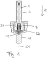
- the gear shaping machine of this embodiment does not have a shaping head slide with which such a stroke position error ⁇ Z could be easily corrected. Instead, the hydraulic systems are now activated, i.e. the system changes from the gear shaping operating state to the stroke position adjustment state. Based on the known thread data of the thread 5, 6, the control of the CNC-controlled gear shaping machine can determine the rotation of the ball pin 1 in the ball pin holder 2 required for stroke position compensation ⁇ Z and can control the CNC-controlled spindle drive of the tool spindle coupled to the ball pin 1 in this operating position accordingly to rotate by the angle of rotation corresponding to the stroke position correction ⁇ Z.
Landscapes
- Engineering & Computer Science (AREA)
- Mechanical Engineering (AREA)
- Gear Processing (AREA)
- Machine Tool Units (AREA)
- Gear Transmission (AREA)
Claims (12)
- Machine à tailler à outil-pignon pour l'usinage de dentures de pièces, comportant :une broche (11, 41) destinée à recevoir un outil d'usinage (60),un dispositif permettant à la broche d'effectuer une course alternative,un entraînement (40) permettant à la broche d'être entraînée en rotation autour de son axe de broche (C1), etun système d'ajustement de la position de course de la machine ;dans laquelle, sous l'effet d'un actionnement du système d'ajustement de la position de course, la position relative axiale de la broche par rapport à l'axe de broche est modifiée par une rotation de broche provoquée par l'entraînement et le système d'ajustement de la position de course comporte une première partie (1) qui est reliée à la broche de manière fixe en rotation sous l'effet de l'actionnement,caractérisée en ce que la première partie (1) présente un évidement axial dans lequel est guidée une partie d'accouplement (3) déplaçable axialement et couplée à la première partie de manière fixe en rotation et par déplacement de laquelle la liaison fixe en rotation de la première partie avec la broche peut être réalisée, le système d'ajustement de la position de course comprenant une deuxième partie (2) dont la liaison fixe en rotation avec la première partie est interrompue sous l'effet de l'actionnement, lesdites première et deuxième parties consistant en des éléments fonctionnels du dispositif permettant à la broche d'effectuer un mouvement alternative.
- Machine à tailler à outil-pignon selon la revendication 1, dans laquelle la partie d'accouplement est configurée sous la forme d'un boulon (3).
- Machine à tailler à outil-pignon selon la revendication 1 ou 2, dans laquelle la liaison fixe en rotation peut être réalisée par conjugaison de forme.
- Machine à tailler à outil-pignon selon l'une des revendications 1 à 3, dans laquelle le déplacement peut s'effectuer de manière hydraulique ou pneumatique.
- Machine à tailler à outil-pignon selon l'une des revendications précédentes, dans laquelle la première et/ou la deuxième partie présentent un filetage (5, 6) et la deuxième et/ou la première partie présentent une partie conjuguée guidée par le filetage.
- Machine à tailler à outil-pignon selon la revendication 5, dans laquelle la première partie (1) présente un filetage extérieur (5) et la deuxième partie (2) présente un filetage intérieur (6) correspondant.
- Machine à tailler à outil-pignon selon l'une des revendications précédentes, dans laquelle un dispositif permettant d'interrompre la liaison résistant à la pression entre la première et la deuxième partie est à fonctionnement hydraulique ou pneumatique, un ou plusieurs organes de serrage filetés (7) sous précontrainte étant notamment relâchés par ledit dispositif.
- Machine à tailler à outil-pignon selon l'une des revendications précédentes, dans laquelle le dispositif permettant à la broche d'effectuer une course alternative est un système à bielle.
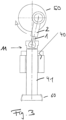
- Machine à tailler à outil-pignon selon l'une des revendications 2 à 8, dans laquelle la première partie est un boulon à tête sphérique (1) de configuration creuse d'un système à bielle de la machine à tailler à outil-pignon, et la faculté de déplacement axial du boulon (3) est assurée au niveau de la tête sphérique (31) du boulon (1).
- Machine à tailler à outil-pignon selon les revendications 3 et 9, dans laquelle la conjugaison de forme est réalisée par une extrémité avant conique du boulon (13) qui épouse la conicité d'un manchon conique (13) installé de manière fixe en rotation dans un évidement central d'une partie terminale de broche (11), ledit évidement central étant tourné vers un coussinet sphérique (32) qui est fixé solidaire en rotation de la partie de broche et dans lequel loge la tête sphérique (31).
- Procédé de taillage à outil-pignon pour l'usinage de dentures de pièces à l'aide d'une machine à tailler à outil-pignon selon l'une des revendications 1 à 10, dans lequel, lors de la réalisation d'un réglage de position de course en vue dudit usinage, il s'effectue, par rapport à l'axe d'une broche susceptible d'être mise en rotation, sous l'effet d'un moteur, autour dudit axe, un positionnement axial de ladite broche par rapport audit axe de broche grâce audit entraînement de broche motorisé, et la réalisation dudit réglage de position de course est caractérisée en ce qu'une liaison fixe en rotation de la broche et d'un dispositif de réglage de position de course est produite par déplacement axial d'une partie d'accouplement qui est déplaçable axialement dans un évidement axial d'une partie du dispositif de réglage de position de course et qui est guidée de manière fixe en rotation avec celle-ci.
- Procédé selon la revendication 11, dans lequel le positionnement axial s'effectue après serrage d'un outil de dimension axiale différente de celle de l'outil précédemment serré.
Applications Claiming Priority (2)
| Application Number | Priority Date | Filing Date | Title |
|---|---|---|---|
| DE102014011145.8A DE102014011145A1 (de) | 2014-07-25 | 2014-07-25 | Maschine zum Bearbeiten von Werkstücken, Anordnung dafür und Verfahren zum Bearbeiten unn Werkstücken |
| PCT/EP2015/001468 WO2016012085A1 (fr) | 2014-07-25 | 2015-07-16 | Machine pour l'usinage de pièces, dispositif pour celle-ci, et procédé d'usinage de pièces |
Publications (2)
| Publication Number | Publication Date |
|---|---|
| EP3172004A1 EP3172004A1 (fr) | 2017-05-31 |
| EP3172004B1 true EP3172004B1 (fr) | 2024-07-03 |
Family
ID=53776548
Family Applications (1)
| Application Number | Title | Priority Date | Filing Date |
|---|---|---|---|
| EP15745395.2A Active EP3172004B1 (fr) | 2014-07-25 | 2015-07-16 | Machine de taillage des engrenages de pièces et procédé de taillage des engrenages de pièces |
Country Status (8)
| Country | Link |
|---|---|
| US (1) | US10286509B2 (fr) |
| EP (1) | EP3172004B1 (fr) |
| JP (1) | JP6592076B2 (fr) |
| KR (1) | KR20170034379A (fr) |
| CN (1) | CN106660149B (fr) |
| DE (1) | DE102014011145A1 (fr) |
| ES (1) | ES2987634T3 (fr) |
| WO (1) | WO2016012085A1 (fr) |
Families Citing this family (2)
| Publication number | Priority date | Publication date | Assignee | Title |
|---|---|---|---|---|
| WO2016091217A1 (fr) | 2014-12-11 | 2016-06-16 | 广州华睿光电材料有限公司 | Complexe métallique organique et polymère, mélange, composition et dispositif électronique organique le contenant et utilisation correspondante |
| CN109909559B (zh) * | 2019-04-17 | 2024-04-05 | 浙江劳伦斯机床有限公司 | 一种万能插齿机构 |
Citations (2)
| Publication number | Priority date | Publication date | Assignee | Title |
|---|---|---|---|---|
| JPS6048920U (ja) * | 1983-09-12 | 1985-04-06 | 三菱重工業株式会社 | 歯車形削盤用カツタ位置調整装置 |
| JPS6327220U (fr) * | 1986-07-31 | 1988-02-23 |
Family Cites Families (32)
| Publication number | Priority date | Publication date | Assignee | Title |
|---|---|---|---|---|
| GB189913139A (en) * | 1899-06-24 | 1900-05-12 | Henry Edmonds | Improved Mechanism for Obtaining Combined Rotary and Reciprocating Movements of Shafts, Spindles, and the like, and for the Conversion of Rotary into Reciprocating Movements in the Case of Slides and Sliding Parts. |
| US1662109A (en) * | 1923-06-07 | 1928-03-13 | Fellows Gear Shaper Co | High-speed-gear-generating machine |
| US2069323A (en) * | 1932-12-14 | 1937-02-02 | Fellows Gear Shaper Co | Helical gear shaping machine |
| US2129858A (en) * | 1934-07-03 | 1938-09-13 | Fellows Gear Shaper Co | Gear generating machine |
| US2055132A (en) * | 1935-03-07 | 1936-09-22 | Mcleod Robert James | Gear shaping machine |
| US2364065A (en) * | 1939-12-12 | 1944-12-05 | Frederichs Georg Gert | Gear shaping machine |
| US2596343A (en) * | 1949-02-09 | 1952-05-13 | Fellows Gear Shaper Co | Gear shaping machine with eccentric cutter relief |
| DE1627364A1 (de) * | 1967-09-02 | 1971-10-07 | Lorenz Maschf | Waelzstossmaschine zur Herstellung von Zahnraedern od.dgl. |
| JPS4839265Y1 (fr) * | 1970-07-09 | 1973-11-19 | ||
| DE2127043A1 (de) * | 1971-06-01 | 1972-12-14 | Seiberlich W | Wälzstoßmaschinen-Hubantrieb mittels Linearmotor |
| JPS5326357B2 (fr) * | 1972-10-19 | 1978-08-01 | ||
| US4125056A (en) | 1977-01-10 | 1978-11-14 | Fellows Corporation | Spindle structure for gear shaping machine or the like |
| JPS5923932B2 (ja) * | 1978-01-30 | 1984-06-06 | 三菱重工業株式会社 | 歯車形削盤 |
| JPS571063Y2 (fr) * | 1979-09-20 | 1982-01-08 | ||
| US4514119A (en) * | 1982-10-26 | 1985-04-30 | Mitsubishi Jukogyo Kabushiki Kaisha | Method of shaping a helical gear |
| US4487535A (en) * | 1983-03-09 | 1984-12-11 | Barber-Colman Company | Gear shaping machine |
| US4606682A (en) * | 1984-09-17 | 1986-08-19 | Miller John R | Gear shaping machine |
| JPS6186126A (ja) * | 1984-10-03 | 1986-05-01 | Karatsu Tekkosho:Kk | 歯車形削り盤のヘリカルガイド構造 |
| JPS6239116A (ja) * | 1985-08-13 | 1987-02-20 | Mitsubishi Heavy Ind Ltd | ギヤシエ−パの無段調整ヘリカルガイド機構 |
| JPH07115257B2 (ja) * | 1986-05-30 | 1995-12-13 | 株式會社唐津鐵工所 | 歯車形削り盤 |
| JPH0432163Y2 (fr) * | 1986-11-12 | 1992-08-03 | ||
| JPH0747248B2 (ja) * | 1988-04-11 | 1995-05-24 | 豊精密工業株式会社 | レリーフ付カッタ往復機構並びにレリーフ付カッタ往復機構の同期化駆動方法 |
| US4978263A (en) * | 1989-06-02 | 1990-12-18 | Sheppard Peter H | Slot forming apparatus |
| JPH03178718A (ja) * | 1989-12-07 | 1991-08-02 | Mitsubishi Heavy Ind Ltd | ギアシェーパ |
| JPH07117136B2 (ja) * | 1990-02-19 | 1995-12-18 | 健 柳沢 | ボールネジ・スプライン装置 |
| DE10209971A1 (de) * | 2002-03-07 | 2003-10-02 | Liebherr Verzahntech Gmbh | Wälzstoßmaschine und Verfahren zum Betrieb einer Wälzstoßmaschine |
| GB0504228D0 (en) * | 2005-03-01 | 2005-04-06 | Westwind Air Bearings Ltd | Machining spindles |
| CN201161321Y (zh) * | 2007-09-29 | 2008-12-10 | 南京二机齿轮机床有限公司 | 插齿刀冲程调整装置 |
| JP5734025B2 (ja) * | 2011-02-28 | 2015-06-10 | 三菱重工業株式会社 | 加工装置 |
| CN103769934A (zh) * | 2012-10-19 | 2014-05-07 | 赵强 | 一种齿轮插刀垂直方向运动机构 |
| JP6074604B2 (ja) * | 2013-02-28 | 2017-02-08 | 株式会社 神崎高級工機製作所 | 削り盤 |
| JP2015186831A (ja) * | 2014-03-27 | 2015-10-29 | 三菱重工業株式会社 | ヘリカルギヤの加工方法、及び加工装置 |
-
2014
- 2014-07-25 DE DE102014011145.8A patent/DE102014011145A1/de active Pending
-
2015
- 2015-07-16 US US15/328,917 patent/US10286509B2/en active Active
- 2015-07-16 WO PCT/EP2015/001468 patent/WO2016012085A1/fr not_active Ceased
- 2015-07-16 KR KR1020177000308A patent/KR20170034379A/ko not_active Ceased
- 2015-07-16 JP JP2017504004A patent/JP6592076B2/ja active Active
- 2015-07-16 CN CN201580035182.9A patent/CN106660149B/zh active Active
- 2015-07-16 ES ES15745395T patent/ES2987634T3/es active Active
- 2015-07-16 EP EP15745395.2A patent/EP3172004B1/fr active Active
Patent Citations (2)
| Publication number | Priority date | Publication date | Assignee | Title |
|---|---|---|---|---|
| JPS6048920U (ja) * | 1983-09-12 | 1985-04-06 | 三菱重工業株式会社 | 歯車形削盤用カツタ位置調整装置 |
| JPS6327220U (fr) * | 1986-07-31 | 1988-02-23 |
Also Published As
| Publication number | Publication date |
|---|---|
| US10286509B2 (en) | 2019-05-14 |
| JP6592076B2 (ja) | 2019-10-16 |
| EP3172004A1 (fr) | 2017-05-31 |
| DE102014011145A1 (de) | 2016-01-28 |
| CN106660149A (zh) | 2017-05-10 |
| WO2016012085A1 (fr) | 2016-01-28 |
| US20170209971A1 (en) | 2017-07-27 |
| JP2017521272A (ja) | 2017-08-03 |
| KR20170034379A (ko) | 2017-03-28 |
| ES2987634T3 (es) | 2024-11-15 |
| CN106660149B (zh) | 2020-01-10 |
Similar Documents
| Publication | Publication Date | Title |
|---|---|---|
| DE4237422C2 (de) | Werkstückhaltevorrichtung für auf Werkzeugmaschinen mehrseitig zu bearbeitende Werkstücke | |
| EP3191245B1 (fr) | Mandrin de serrage | |
| EP3507060B1 (fr) | Dispositif d'accouplement | |
| EP2829339B1 (fr) | Dispositif de positionnement pour pièces à usiner, machine-outil dotée d'un tel dispositif de positionnement, procédé de positionnement de pièces à usiner | |
| EP3172004B1 (fr) | Machine de taillage des engrenages de pièces et procédé de taillage des engrenages de pièces | |
| DE102011089462B4 (de) | Feinbearbeitungsmaschine, Kupplungseinrichtung für Feinbearbeitungsmaschine und Bearbeitungswerkzeug | |
| EP1428612B1 (fr) | Dispositif et procédé de positionnement angulaire de pièces excentriques telles que des villebrequins, par l'intermédiaire de mâchoires montées sur une lunette de centrage | |
| EP2853319A1 (fr) | Dispositif destiné au forgeage d'un bloc creux pré-percé | |
| CH698147B1 (de) | Schleifmaschine und Verfahren zum Einrichten eines Werkstückträgers an einer Schleifmaschine. | |
| DE2535718C3 (de) | Tieflochbohreinrichtung für Mehrspindel-Drehautomaten | |
| DE2158813A1 (de) | Vorrichtung zum einstellen eines werkzeugschlittens einer werkzeugmaschine, insbesondere einer drehmaschine | |
| EP0123976B1 (fr) | Chariot réglable pour cylindre à imprimer | |
| DE3518287C2 (fr) | ||
| AT240130B (de) | Bohrstange | |
| CH718192A1 (de) | Aufnahmeflansch für einen Werkzeugkörper. | |
| DE102013003771A1 (de) | Verzahnmaschine zum Bearbeiten eines Werkstücks und Vefahren zum Bearbeiten einer Kurbelwelle | |
| EP3890911A2 (fr) | Tête de perçage et procédé pour le tournage de trous borgnes | |
| DE1141513B (de) | Vorrichtung zum Innengewindeschneiden, insbesondere in Rohrmuffen | |
| EP3672748B1 (fr) | Dispositif de serrage d'une pièce à usiner | |
| DE19832177C2 (de) | Vorrichtung zur Aufnahme einer Einheit mit rotierender Spindel, insbesondere eines angetriebenen Werkzeugs bei einer Werkzeugmaschine | |
| DE2006761C3 (de) | Werkstoff anschlag für selbsttätig arbeitende Drehmaschinen" | |
| DE1800271C3 (de) | Spannfutter tür Drehmaschinen | |
| DE741568C (fr) | ||
| DE1602755C3 (de) | Bohrkopf mit einem Spindelschaft | |
| DE2741100A1 (de) | Pinoleneinheit fuer werkzeugmaschinen |
Legal Events
| Date | Code | Title | Description |
|---|---|---|---|
| STAA | Information on the status of an ep patent application or granted ep patent |
Free format text: STATUS: THE INTERNATIONAL PUBLICATION HAS BEEN MADE |
|
| PUAI | Public reference made under article 153(3) epc to a published international application that has entered the european phase |
Free format text: ORIGINAL CODE: 0009012 |
|
| STAA | Information on the status of an ep patent application or granted ep patent |
Free format text: STATUS: REQUEST FOR EXAMINATION WAS MADE |
|
| 17P | Request for examination filed |
Effective date: 20170109 |
|
| AK | Designated contracting states |
Kind code of ref document: A1 Designated state(s): AL AT BE BG CH CY CZ DE DK EE ES FI FR GB GR HR HU IE IS IT LI LT LU LV MC MK MT NL NO PL PT RO RS SE SI SK SM TR |
|
| AX | Request for extension of the european patent |
Extension state: BA ME |
|
| DAV | Request for validation of the european patent (deleted) | ||
| DAX | Request for extension of the european patent (deleted) | ||
| STAA | Information on the status of an ep patent application or granted ep patent |
Free format text: STATUS: EXAMINATION IS IN PROGRESS |
|
| 17Q | First examination report despatched |
Effective date: 20210409 |
|
| GRAP | Despatch of communication of intention to grant a patent |
Free format text: ORIGINAL CODE: EPIDOSNIGR1 |
|
| STAA | Information on the status of an ep patent application or granted ep patent |
Free format text: STATUS: GRANT OF PATENT IS INTENDED |
|
| INTG | Intention to grant announced |
Effective date: 20240318 |
|
| GRAS | Grant fee paid |
Free format text: ORIGINAL CODE: EPIDOSNIGR3 |
|
| GRAA | (expected) grant |
Free format text: ORIGINAL CODE: 0009210 |
|
| STAA | Information on the status of an ep patent application or granted ep patent |
Free format text: STATUS: THE PATENT HAS BEEN GRANTED |
|
| P01 | Opt-out of the competence of the unified patent court (upc) registered |
Effective date: 20240522 |
|
| AK | Designated contracting states |
Kind code of ref document: B1 Designated state(s): AL AT BE BG CH CY CZ DE DK EE ES FI FR GB GR HR HU IE IS IT LI LT LU LV MC MK MT NL NO PL PT RO RS SE SI SK SM TR |
|
| REG | Reference to a national code |
Ref country code: CH Ref legal event code: EP |
|
| REG | Reference to a national code |
Ref country code: DE Ref legal event code: R096 Ref document number: 502015016889 Country of ref document: DE |
|
| PGFP | Annual fee paid to national office [announced via postgrant information from national office to epo] |
Ref country code: ES Payment date: 20240801 Year of fee payment: 10 |
|
| PGFP | Annual fee paid to national office [announced via postgrant information from national office to epo] |
Ref country code: CZ Payment date: 20240719 Year of fee payment: 10 |
|
| REG | Reference to a national code |
Ref country code: LT Ref legal event code: MG9D |
|
| REG | Reference to a national code |
Ref country code: NL Ref legal event code: MP Effective date: 20240703 |
|
| REG | Reference to a national code |
Ref country code: ES Ref legal event code: FG2A Ref document number: 2987634 Country of ref document: ES Kind code of ref document: T3 Effective date: 20241115 |
|
| PG25 | Lapsed in a contracting state [announced via postgrant information from national office to epo] |
Ref country code: PT Free format text: LAPSE BECAUSE OF FAILURE TO SUBMIT A TRANSLATION OF THE DESCRIPTION OR TO PAY THE FEE WITHIN THE PRESCRIBED TIME-LIMIT Effective date: 20241104 |
|
| PG25 | Lapsed in a contracting state [announced via postgrant information from national office to epo] |
Ref country code: NL Free format text: LAPSE BECAUSE OF FAILURE TO SUBMIT A TRANSLATION OF THE DESCRIPTION OR TO PAY THE FEE WITHIN THE PRESCRIBED TIME-LIMIT Effective date: 20240703 |
|
| PG25 | Lapsed in a contracting state [announced via postgrant information from national office to epo] |
Ref country code: PT Free format text: LAPSE BECAUSE OF FAILURE TO SUBMIT A TRANSLATION OF THE DESCRIPTION OR TO PAY THE FEE WITHIN THE PRESCRIBED TIME-LIMIT Effective date: 20241104 Ref country code: NL Free format text: LAPSE BECAUSE OF FAILURE TO SUBMIT A TRANSLATION OF THE DESCRIPTION OR TO PAY THE FEE WITHIN THE PRESCRIBED TIME-LIMIT Effective date: 20240703 |
|
| PG25 | Lapsed in a contracting state [announced via postgrant information from national office to epo] |
Ref country code: NO Free format text: LAPSE BECAUSE OF FAILURE TO SUBMIT A TRANSLATION OF THE DESCRIPTION OR TO PAY THE FEE WITHIN THE PRESCRIBED TIME-LIMIT Effective date: 20241003 |
|
| PG25 | Lapsed in a contracting state [announced via postgrant information from national office to epo] |
Ref country code: GR Free format text: LAPSE BECAUSE OF FAILURE TO SUBMIT A TRANSLATION OF THE DESCRIPTION OR TO PAY THE FEE WITHIN THE PRESCRIBED TIME-LIMIT Effective date: 20241004 Ref country code: FI Free format text: LAPSE BECAUSE OF FAILURE TO SUBMIT A TRANSLATION OF THE DESCRIPTION OR TO PAY THE FEE WITHIN THE PRESCRIBED TIME-LIMIT Effective date: 20240703 Ref country code: PL Free format text: LAPSE BECAUSE OF FAILURE TO SUBMIT A TRANSLATION OF THE DESCRIPTION OR TO PAY THE FEE WITHIN THE PRESCRIBED TIME-LIMIT Effective date: 20240703 |
|
| PG25 | Lapsed in a contracting state [announced via postgrant information from national office to epo] |
Ref country code: BG Free format text: LAPSE BECAUSE OF FAILURE TO SUBMIT A TRANSLATION OF THE DESCRIPTION OR TO PAY THE FEE WITHIN THE PRESCRIBED TIME-LIMIT Effective date: 20240703 |
|
| PG25 | Lapsed in a contracting state [announced via postgrant information from national office to epo] |
Ref country code: LV Free format text: LAPSE BECAUSE OF FAILURE TO SUBMIT A TRANSLATION OF THE DESCRIPTION OR TO PAY THE FEE WITHIN THE PRESCRIBED TIME-LIMIT Effective date: 20240703 |
|
| PG25 | Lapsed in a contracting state [announced via postgrant information from national office to epo] |
Ref country code: IS Free format text: LAPSE BECAUSE OF FAILURE TO SUBMIT A TRANSLATION OF THE DESCRIPTION OR TO PAY THE FEE WITHIN THE PRESCRIBED TIME-LIMIT Effective date: 20241103 |
|
| PG25 | Lapsed in a contracting state [announced via postgrant information from national office to epo] |
Ref country code: HR Free format text: LAPSE BECAUSE OF FAILURE TO SUBMIT A TRANSLATION OF THE DESCRIPTION OR TO PAY THE FEE WITHIN THE PRESCRIBED TIME-LIMIT Effective date: 20240703 |
|
| PG25 | Lapsed in a contracting state [announced via postgrant information from national office to epo] |
Ref country code: RS Free format text: LAPSE BECAUSE OF FAILURE TO SUBMIT A TRANSLATION OF THE DESCRIPTION OR TO PAY THE FEE WITHIN THE PRESCRIBED TIME-LIMIT Effective date: 20241003 |
|
| PG25 | Lapsed in a contracting state [announced via postgrant information from national office to epo] |
Ref country code: RS Free format text: LAPSE BECAUSE OF FAILURE TO SUBMIT A TRANSLATION OF THE DESCRIPTION OR TO PAY THE FEE WITHIN THE PRESCRIBED TIME-LIMIT Effective date: 20241003 Ref country code: PL Free format text: LAPSE BECAUSE OF FAILURE TO SUBMIT A TRANSLATION OF THE DESCRIPTION OR TO PAY THE FEE WITHIN THE PRESCRIBED TIME-LIMIT Effective date: 20240703 Ref country code: NO Free format text: LAPSE BECAUSE OF FAILURE TO SUBMIT A TRANSLATION OF THE DESCRIPTION OR TO PAY THE FEE WITHIN THE PRESCRIBED TIME-LIMIT Effective date: 20241003 Ref country code: LV Free format text: LAPSE BECAUSE OF FAILURE TO SUBMIT A TRANSLATION OF THE DESCRIPTION OR TO PAY THE FEE WITHIN THE PRESCRIBED TIME-LIMIT Effective date: 20240703 Ref country code: IS Free format text: LAPSE BECAUSE OF FAILURE TO SUBMIT A TRANSLATION OF THE DESCRIPTION OR TO PAY THE FEE WITHIN THE PRESCRIBED TIME-LIMIT Effective date: 20241103 Ref country code: HR Free format text: LAPSE BECAUSE OF FAILURE TO SUBMIT A TRANSLATION OF THE DESCRIPTION OR TO PAY THE FEE WITHIN THE PRESCRIBED TIME-LIMIT Effective date: 20240703 Ref country code: GR Free format text: LAPSE BECAUSE OF FAILURE TO SUBMIT A TRANSLATION OF THE DESCRIPTION OR TO PAY THE FEE WITHIN THE PRESCRIBED TIME-LIMIT Effective date: 20241004 Ref country code: FI Free format text: LAPSE BECAUSE OF FAILURE TO SUBMIT A TRANSLATION OF THE DESCRIPTION OR TO PAY THE FEE WITHIN THE PRESCRIBED TIME-LIMIT Effective date: 20240703 Ref country code: BG Free format text: LAPSE BECAUSE OF FAILURE TO SUBMIT A TRANSLATION OF THE DESCRIPTION OR TO PAY THE FEE WITHIN THE PRESCRIBED TIME-LIMIT Effective date: 20240703 |
|
| REG | Reference to a national code |
Ref country code: CH Ref legal event code: PL |
|
| PG25 | Lapsed in a contracting state [announced via postgrant information from national office to epo] |
Ref country code: LU Free format text: LAPSE BECAUSE OF NON-PAYMENT OF DUE FEES Effective date: 20240716 |
|
| PG25 | Lapsed in a contracting state [announced via postgrant information from national office to epo] |
Ref country code: LU Free format text: LAPSE BECAUSE OF NON-PAYMENT OF DUE FEES Effective date: 20240716 |
|
| REG | Reference to a national code |
Ref country code: DE Ref legal event code: R097 Ref document number: 502015016889 Country of ref document: DE |
|
| PG25 | Lapsed in a contracting state [announced via postgrant information from national office to epo] |
Ref country code: RO Free format text: LAPSE BECAUSE OF FAILURE TO SUBMIT A TRANSLATION OF THE DESCRIPTION OR TO PAY THE FEE WITHIN THE PRESCRIBED TIME-LIMIT Effective date: 20240703 Ref country code: DK Free format text: LAPSE BECAUSE OF FAILURE TO SUBMIT A TRANSLATION OF THE DESCRIPTION OR TO PAY THE FEE WITHIN THE PRESCRIBED TIME-LIMIT Effective date: 20240703 Ref country code: SM Free format text: LAPSE BECAUSE OF FAILURE TO SUBMIT A TRANSLATION OF THE DESCRIPTION OR TO PAY THE FEE WITHIN THE PRESCRIBED TIME-LIMIT Effective date: 20240703 |
|
| PG25 | Lapsed in a contracting state [announced via postgrant information from national office to epo] |
Ref country code: MC Free format text: LAPSE BECAUSE OF FAILURE TO SUBMIT A TRANSLATION OF THE DESCRIPTION OR TO PAY THE FEE WITHIN THE PRESCRIBED TIME-LIMIT Effective date: 20240703 Ref country code: CH Free format text: LAPSE BECAUSE OF NON-PAYMENT OF DUE FEES Effective date: 20240731 Ref country code: EE Free format text: LAPSE BECAUSE OF FAILURE TO SUBMIT A TRANSLATION OF THE DESCRIPTION OR TO PAY THE FEE WITHIN THE PRESCRIBED TIME-LIMIT Effective date: 20240703 Ref country code: BE Free format text: LAPSE BECAUSE OF NON-PAYMENT OF DUE FEES Effective date: 20240731 |
|
| PG25 | Lapsed in a contracting state [announced via postgrant information from national office to epo] |
Ref country code: SK Free format text: LAPSE BECAUSE OF FAILURE TO SUBMIT A TRANSLATION OF THE DESCRIPTION OR TO PAY THE FEE WITHIN THE PRESCRIBED TIME-LIMIT Effective date: 20240703 |
|
| PLBE | No opposition filed within time limit |
Free format text: ORIGINAL CODE: 0009261 |
|
| STAA | Information on the status of an ep patent application or granted ep patent |
Free format text: STATUS: NO OPPOSITION FILED WITHIN TIME LIMIT |
|
| REG | Reference to a national code |
Ref country code: BE Ref legal event code: MM Effective date: 20240731 |
|
| 26N | No opposition filed |
Effective date: 20250404 |
|
| GBPC | Gb: european patent ceased through non-payment of renewal fee |
Effective date: 20241003 |
|
| PG25 | Lapsed in a contracting state [announced via postgrant information from national office to epo] |
Ref country code: GB Free format text: LAPSE BECAUSE OF NON-PAYMENT OF DUE FEES Effective date: 20241003 |
|
| PG25 | Lapsed in a contracting state [announced via postgrant information from national office to epo] |
Ref country code: IT Free format text: LAPSE BECAUSE OF NON-PAYMENT OF DUE FEES Effective date: 20240716 |
|
| PG25 | Lapsed in a contracting state [announced via postgrant information from national office to epo] |
Ref country code: FR Free format text: LAPSE BECAUSE OF NON-PAYMENT OF DUE FEES Effective date: 20240903 |
|
| PG25 | Lapsed in a contracting state [announced via postgrant information from national office to epo] |
Ref country code: IE Free format text: LAPSE BECAUSE OF NON-PAYMENT OF DUE FEES Effective date: 20240716 |
|
| PG25 | Lapsed in a contracting state [announced via postgrant information from national office to epo] |
Ref country code: SE Free format text: LAPSE BECAUSE OF FAILURE TO SUBMIT A TRANSLATION OF THE DESCRIPTION OR TO PAY THE FEE WITHIN THE PRESCRIBED TIME-LIMIT Effective date: 20240703 |
|
| REG | Reference to a national code |
Ref country code: AT Ref legal event code: MM01 Ref document number: 1699327 Country of ref document: AT Kind code of ref document: T Effective date: 20240716 |
|
| PGFP | Annual fee paid to national office [announced via postgrant information from national office to epo] |
Ref country code: DE Payment date: 20250729 Year of fee payment: 11 |
|
| PG25 | Lapsed in a contracting state [announced via postgrant information from national office to epo] |
Ref country code: AT Free format text: LAPSE BECAUSE OF NON-PAYMENT OF DUE FEES Effective date: 20240716 |
|
| PG25 | Lapsed in a contracting state [announced via postgrant information from national office to epo] |
Ref country code: CY Free format text: LAPSE BECAUSE OF FAILURE TO SUBMIT A TRANSLATION OF THE DESCRIPTION OR TO PAY THE FEE WITHIN THE PRESCRIBED TIME-LIMIT; INVALID AB INITIO Effective date: 20150716 |
|
| PG25 | Lapsed in a contracting state [announced via postgrant information from national office to epo] |
Ref country code: HU Free format text: LAPSE BECAUSE OF FAILURE TO SUBMIT A TRANSLATION OF THE DESCRIPTION OR TO PAY THE FEE WITHIN THE PRESCRIBED TIME-LIMIT; INVALID AB INITIO Effective date: 20150716 |
|
| PG25 | Lapsed in a contracting state [announced via postgrant information from national office to epo] |
Ref country code: CZ Free format text: LAPSE BECAUSE OF NON-PAYMENT OF DUE FEES Effective date: 20250716 |