EP3172071B1 - Dispositif de réglage du carrossage et/ou du pincement d'un véhicule à moteur - Google Patents
Dispositif de réglage du carrossage et/ou du pincement d'un véhicule à moteur Download PDFInfo
- Publication number
- EP3172071B1 EP3172071B1 EP15730067.4A EP15730067A EP3172071B1 EP 3172071 B1 EP3172071 B1 EP 3172071B1 EP 15730067 A EP15730067 A EP 15730067A EP 3172071 B1 EP3172071 B1 EP 3172071B1
- Authority
- EP
- European Patent Office
- Prior art keywords
- wheel
- vehicle
- bearing
- torque
- axle
- Prior art date
- Legal status (The legal status is an assumption and is not a legal conclusion. Google has not performed a legal analysis and makes no representation as to the accuracy of the status listed.)
- Not-in-force
Links
Images


Classifications
-
- B—PERFORMING OPERATIONS; TRANSPORTING
- B60—VEHICLES IN GENERAL
- B60G—VEHICLE SUSPENSION ARRANGEMENTS
- B60G17/00—Resilient suspensions having means for adjusting the spring or vibration-damper characteristics, for regulating the distance between a supporting surface and a sprung part of vehicle or for locking suspension during use to meet varying vehicular or surface conditions, e.g. due to speed or load
- B60G17/015—Resilient suspensions having means for adjusting the spring or vibration-damper characteristics, for regulating the distance between a supporting surface and a sprung part of vehicle or for locking suspension during use to meet varying vehicular or surface conditions, e.g. due to speed or load the regulating means comprising electric or electronic elements
- B60G17/0152—Resilient suspensions having means for adjusting the spring or vibration-damper characteristics, for regulating the distance between a supporting surface and a sprung part of vehicle or for locking suspension during use to meet varying vehicular or surface conditions, e.g. due to speed or load the regulating means comprising electric or electronic elements characterised by the action on a particular type of suspension unit
-
- B—PERFORMING OPERATIONS; TRANSPORTING
- B60—VEHICLES IN GENERAL
- B60G—VEHICLE SUSPENSION ARRANGEMENTS
- B60G17/00—Resilient suspensions having means for adjusting the spring or vibration-damper characteristics, for regulating the distance between a supporting surface and a sprung part of vehicle or for locking suspension during use to meet varying vehicular or surface conditions, e.g. due to speed or load
- B60G17/015—Resilient suspensions having means for adjusting the spring or vibration-damper characteristics, for regulating the distance between a supporting surface and a sprung part of vehicle or for locking suspension during use to meet varying vehicular or surface conditions, e.g. due to speed or load the regulating means comprising electric or electronic elements
- B60G17/016—Resilient suspensions having means for adjusting the spring or vibration-damper characteristics, for regulating the distance between a supporting surface and a sprung part of vehicle or for locking suspension during use to meet varying vehicular or surface conditions, e.g. due to speed or load the regulating means comprising electric or electronic elements characterised by their responsiveness, when the vehicle is travelling, to specific motion, a specific condition, or driver input
- B60G17/0164—Resilient suspensions having means for adjusting the spring or vibration-damper characteristics, for regulating the distance between a supporting surface and a sprung part of vehicle or for locking suspension during use to meet varying vehicular or surface conditions, e.g. due to speed or load the regulating means comprising electric or electronic elements characterised by their responsiveness, when the vehicle is travelling, to specific motion, a specific condition, or driver input mainly during accelerating or braking
-
- B—PERFORMING OPERATIONS; TRANSPORTING
- B62—LAND VEHICLES FOR TRAVELLING OTHERWISE THAN ON RAILS
- B62D—MOTOR VEHICLES; TRAILERS
- B62D17/00—Means on vehicles for adjusting camber, castor, or toe-in
-
- B—PERFORMING OPERATIONS; TRANSPORTING
- B60—VEHICLES IN GENERAL
- B60G—VEHICLE SUSPENSION ARRANGEMENTS
- B60G2200/00—Indexing codes relating to suspension types
- B60G2200/40—Indexing codes relating to the wheels in the suspensions
- B60G2200/46—Indexing codes relating to the wheels in the suspensions camber angle
-
- B—PERFORMING OPERATIONS; TRANSPORTING
- B60—VEHICLES IN GENERAL
- B60G—VEHICLE SUSPENSION ARRANGEMENTS
- B60G2200/00—Indexing codes relating to suspension types
- B60G2200/40—Indexing codes relating to the wheels in the suspensions
- B60G2200/462—Toe-in/out
-
- B—PERFORMING OPERATIONS; TRANSPORTING
- B60—VEHICLES IN GENERAL
- B60G—VEHICLE SUSPENSION ARRANGEMENTS
- B60G2200/00—Indexing codes relating to suspension types
- B60G2200/40—Indexing codes relating to the wheels in the suspensions
- B60G2200/462—Toe-in/out
- B60G2200/4622—Alignment adjustment
-
- B—PERFORMING OPERATIONS; TRANSPORTING
- B60—VEHICLES IN GENERAL
- B60G—VEHICLE SUSPENSION ARRANGEMENTS
- B60G2202/00—Indexing codes relating to the type of spring, damper or actuator
- B60G2202/40—Type of actuator
- B60G2202/42—Electric actuator
-
- B—PERFORMING OPERATIONS; TRANSPORTING
- B60—VEHICLES IN GENERAL
- B60G—VEHICLE SUSPENSION ARRANGEMENTS
- B60G2206/00—Indexing codes related to the manufacturing of suspensions: constructional features, the materials used, procedures or tools
- B60G2206/01—Constructional features of suspension elements, e.g. arms, dampers, springs
- B60G2206/50—Constructional features of wheel supports or knuckles, e.g. steering knuckles, spindle attachments
-
- B—PERFORMING OPERATIONS; TRANSPORTING
- B60—VEHICLES IN GENERAL
- B60Y—INDEXING SCHEME RELATING TO ASPECTS CROSS-CUTTING VEHICLE TECHNOLOGY
- B60Y2300/00—Purposes or special features of road vehicle drive control systems
- B60Y2300/02—Control of vehicle driving stability
-
- B—PERFORMING OPERATIONS; TRANSPORTING
- B60—VEHICLES IN GENERAL
- B60Y—INDEXING SCHEME RELATING TO ASPECTS CROSS-CUTTING VEHICLE TECHNOLOGY
- B60Y2400/00—Special features of vehicle units
- B60Y2400/40—Actuators for moving a controlled member
- B60Y2400/405—Electric motors actuators
Definitions
- the invention relates to a device for adjusting the camber and / or track of a motor vehicle wheel according to the preamble of claim 1.
- a device in which a wheel carrier for a vehicle is designed in several parts, with a wheel-side support member and an axle-side guide member and arranged therebetween rotary members.
- a wheel bearing is integrated, in which a wheel hub portion of a, the vehicle wheel-bearing wheel flange is rotatably mounted.
- On the axle-side guide part of the handlebars of the suspension of the vehicle are steerable.
- the rotating parts arranged therebetween cooperate with inclined surfaces which define an axis of rotation of the wheel-side rotary part which is inclined to the axis of rotation of the axle-side rotary part. In this way, in the case of a rotary drive of at least one of the rotary parts, the wheel-side rotary part can be pivoted about a tumbling point for lane or camber adjustment of the vehicle wheel.
- the braking forces and moments generated by the brake system are conducted via the wheel carrier to the vehicle body, whereby the danger exists that the camber and / or toe behavior of the wheel carrier is influenced unintentionally.
- the wheel-side carrier part is acted upon by the brake caliper in braking engagement with a braking torque.
- the wheel-side support member in the DE 10 2009 058 489 A1 via a torque bridge, that is a universal joint, supported on the axle-side guide member.
- reaction torque acts directly on the rotary drive of the rotating parts and does not necessarily have to be identical to the total vehicle wheel torque. Rather, the reaction torque may also be different from the total vehicle wheel torque, depending on, inter alia, the current rotational positions of the rotary parts and / or on the current position of the inclined plane formed between the rotary parts.
- From the DE 10 2008 048568 A1 is a generic device for adjusting a camber and / or lane of a vehicle wheel known.
- the object of the invention is to provide a device in which automatically without intervention of the rotary drive of the rotary parts during braking a fall and / or lane change is reduced in a simple manner.
- Efindungsdorf the torque bridge between the wheel-side support member and the axle-side guide member is designed as a torque transmitting element that generates a force component in the support of the acted upon by the brake torque support member on the guide member, with which the wheel-side support member is acted upon braking.
- the torque transmitting element thus converts the braking torque into the force component.
- the torque transmission element is at least one coupling rod, which can be claimed both on train and on pressure.
- the coupling rod is articulated in each case at a wheel-side articulation point on the wheel-side carrier part and on an axle-side articulation point about the axle-side guide part.
- Conventional torque bridges such as a universal joint or a metal bellows, are designed solely for proper braking torque support, that is torsionally stiff with respect to the wheel axle, but sufficiently yielding in the vehicle transverse direction, not to the tumbling motion of the wheel-side rotary member coupled thereto carrier part affect.
- a torque bridge is not able to exert the above-mentioned directed force component on the wheel-side support member.
- the coupling rod is arranged between the wheel-side support member and the axle-side guide member, that this is caulked in the exercise of the braking torque therebetween, that is, the coupling rod acted on its wheel-side articulation point, the wheel-side support member with the directed force component.
- the wheel and axle-side articulation points of the torque transmitting element, that is, the coupling rod are preferably not aligned in the vehicle transverse direction in alignment with each other, but purely by way of example rather spaced apart in the vehicle longitudinal direction by a longitudinal offset. In this way, the above-described Stemmrial is achieved in the braking operation, in which the coupling rod acts on the carrier part with the directed force component, with the inter alia, a fall momentum change is reduced, resulting from the Bremsnickaus GmbH.
- the exact location of the articulation points of the torque transmitting element depends on the geometric conditions of the wheel carrier. With knowledge of the invention, the skilled person with the aid of specialist literature (such as the textbook “joints and propeller shafts" of Schmelz, Seherr-Thoss, Aucktor) calculate the exact location of the articulation points directly and clearly.
- the positions of the articulation points K1, K2 of the torque transmission element can be determined such that in the complete movement space of the vehicle wheel, that is, for example in a toe angle range of ⁇ 6.5 ° and in a camber angle range between -5 ° and + 2.5 °, the lowest possible residual reaction torque acting on the rotating parts during the braking process.
- the remaining torque is calculated from the difference between the counter-torque exerted by the torque-transmitting element and the above-mentioned total vehicle wheel torque.
- the articulation points may be positioned within the instantaneous center viewed in the vehicle transverse direction.
- the articulation points can be positioned in front of and behind the instantaneous pole.
- the articulation points can also be positioned offset to the instantaneous pole. The articulation points can thus, viewed in the vehicle transverse direction, not be aligned in alignment one behind the other, but be spaced apart in the vehicle longitudinal direction by a distance.
- the wheel-side carrier part of the wheel carrier can be supported on the wheel-side rotary part via a rotary bearing.
- a wheel bearing can be integrated in the wheel-side rotary part.
- the wheel bearing is a hub portion of a, the vehicle wheel bearing Wheel flange rotatably mounted.
- the wheel-side support member carries only the caliper and optionally the drive motor for the wheel-side rotary member.
- the bearing between the wheel-side rotary member and the wheel-side support member is taken from the Radkrafthne and relieved in terms of strength.
- only three bearing points are connected in series in the wheel power flow.
- the fourth bearing point that is, the pivot bearing between the wheel-side support member and the wheel-side rotary member, however, can be made smaller, since the forces acting on this pivot bearing and moments of, for example, the brake system are much lower. Furthermore, increases by the elimination of the fourth bearing point of the Radkraftlig the lintel stiffness of the bearing assembly, whereby the remaining bearings can be made smaller again with constant lintel stiffness. In sum, compared with the prior art, the space requirement and the component weight of the device are considerably reduced.
- the wheel-side support member may be arranged radially outside of the wheel-side rotary member, whereby the device can be made particularly compact in the axial direction.
- the support member may be supported via a radially inner bearing jacket surface with the interposition of the pivot bearing on a radially outer bearing surface of the wheel-side rotary member.
- the axle-side rotary member and the wheel-side rotary member may each be drivingly connected to a drive motor.
- the rotary parts can each be components of a gear drive, in which the electric motor drives the axle-side and / or wheel-side rotary part via a gear stage. In the same direction or in opposite directions rotation of the rotating parts, a pivoting of the support member to a predetermined track and / or camber angle.
- a particularly space-saving arrangement results when the wheel-side rotary member has a gear portion, which is part of the above-mentioned gear drive and is arranged in the axial direction between the support part support point and the inclined surface of the wheel-side rotary member.
- the wheel carrier may have an axle-side guide member.
- the handlebars of the suspension of the vehicle can be articulated.
- the guide member can be decoupled motion, that is, be supported on the axle-side rotary member via a pivot bearing.
- the guide member may, similar to the wheel-side support member, be arranged radially outside of the axle-side rotary member. In this case, the guide member may be supported on the axle-side rotary member via a radially inner bearing.
- FIG. 1 For the sake of easier understanding of the invention, a roughly schematic representation of a wheel carrier 1 of a vehicle wheel 13 not encompassed by the invention and known from the prior art is shown.
- the wheel carrier 1 has a carrier part 3, in which a wheel flange 5 with its hub portion 7 is rotatably mounted in a wheel bearing 12. At the wheel flange 5, a brake disk 11 and a vehicle wheel 13 is mounted with its rim. The brake disk 11 is part of a brake system together with a brake caliper 15 mounted on the carrier part 3.
- the wheel carrier 1, a guide member 17, on which in the Fig. 1 by way of example a link 19 of the suspension is articulated.
- two rotary parts 21, 23 are provided as adjusting elements.
- the rotary member 21 is rotatably connected to the support member 3 to form a rotary member axis 20 at a bearing 32.
- the rotating part 23 is connected to the guide member 17 to form the axis of rotation 22 at a bearing 35.
- the two rotating parts 21, 23 connected via planar inclined surfaces 25, 27 to each other in slide bearing and a rotation axis 24 rotatable with each other.
- the axis of rotation 24 is in the Fig. 1 aligned perpendicular to the inclined surfaces 25, 27 and at a defined angle to the axis of rotation 22 of the axle-side rotary member 23 inclined.
- the rotary member axis 20 is identical in position to the wheel axle.
- the rotary member 21 may not be arranged coaxially with the wheel axle, but the rotary member axis 20 and the wheel axle may be inclined to each other.
- an electric servomotor 29 is provided in each case, which is connected to the rotary parts 21, 23 via gear drives 30 driven.
- the two rotating parts 21, 23 are rotated in the same direction or in opposite directions in both directions of rotation, whereby the support member 3 relative to the guide member 17 is a pivoting movement or wobble about a Momentanpol MP ( Fig. 2 to 5 ) and thus changes the toe angle and / or the camber angle of the vehicle wheel 13 accordingly.
- FIG. 2 the wheel carrier 1 according to the invention is shown.
- the two rotating parts 21, 23 are no longer on plane inclined surfaces 25, 27 in abutment to define the inclined axis of rotation 24, but at a pivot bearing point 31st
- the wheel bearing 12 is no longer directly integrated in the wheel-side support member 3, but rather directly within the wheel-side rotary member 21.
- the outer races and the inner bearings of the wheel bearing 12 are purely exemplary incorporated directly in the inner circumference of the wheel-side rotary member 21 and directly in the outer periphery of the hub portion 7 of the wheel flange 5. Accordingly serves in the Fig. 2 On the outer circumference of the wheel-side rotary member 21 in the vehicle transverse direction y outside the support member 3 via a bearing 43 radially outwardly supported on the wheel-side rotary member 21.
- the bearing 43 must be designed so that tilting moments can be absorbed.
- the wheel bearing 12 can be made removable, with a radially outer bearing housing, which is removable, that is, for example, in a press fit or by screwing, is mounted on the inner circumference of the rotary member 21, and / or with a radially inner bearing housing, which is mountable on the outer circumference of the wheel hub 5.
- the bearing point 43 and the pivot bearing point 31 are formed purely by way of example on axially opposite sides of the rotary part 21, with a gear section 47 being positioned therebetween, which is part of the gear drive 30 (FIG. Fig. 1 ).
- the axle-side guide member 17 is - analogous to the wheel-side support member 3 - supported on a rotary bearing 51 radially outward on the axle-side rotary member 23.
- the gear portion 55 of the axle-side rotary member 23 is positioned in an annular space 57 which is bounded in the vehicle transverse direction y outwardly by the pivot bearing 51 and is bounded inwardly by a ring seal 59 which is disposed between the guide member 17 and the axle-side rotary member 23.
- the invention carries the wheel-side support member 3 - in addition to, for example, an electronic parking brake - only the caliper 15 and the drive motor 29 for the wheel-side rotary member 21, but no longer the wheel bearing 12.
- This is specifically arranged between the support member 3 and the wheel-side rotary member 21 Pivot bearing 43 taken from the wheel power flow.
- a coupling rod 61 mounted between the support part 3 and the guide part 17 is in the Fig. 2 .
- This acts as a torque transmission element, via the torques, in particular a braking torque and / or engine torque of the outer rotary drive 29, from the support member 3 to the guide member 17 is transferable, namely by bridging the axis and Wheel-side rotating parts 21, 23.
- the coupling rod 61 is arranged for example radially outside a circumferential rubber boot 63, which seals the rotating parts 21, 23 and their bearings dirt-tight.
- the coupling rod 61 is positioned with its articulation points K1 and K2 on the wheel-side carrier part 3 and on the axle-side guide part 17 in such a way that a directed force component F (FIG. Fig. 3 or 4 ) results, with which the wheel-side support member 3 is acted upon.
- a braking force longitudinal component F B, x acts on the vehicle wheel 13, of which in the Fig. 4 by way of example a braking force longitudinal component F B, x is highlighted.
- the braking force longitudinal component F B, x acts on the wheel center R M , which in the Fig. 4 is spaced by a lever arm from the instantaneous pole MP, whereby a longitudinal moment M B, x is generated, which presses the vehicle wheel 13 in the direction of the toe.
- the longitudinal moment M B, x is transmitted via the hub portion 7 of the wheel flange 5 and the wheel bearing 12 except for the wheel-side rotary member 21.
- moments M B, x and M B, z add up (possibly together with other, occurring during braking moments) to a total vehicle wheel M tires , which acts as a reaction torque on the rotating parts 21, 23.
- the total vehicle wheel torque M tires can, but need not necessarily be identical to the reaction torque, which acts directly on the rotary drive of the rotary parts 21, 23. Rather, it can the reaction torque also be different from the total vehicle wheel M tires . This depends, for example, on the current rotational positions of the turned parts, on the current position of the inclined plane formed between the turned parts and / or on the actuator's own translation.
- the total vehicle wheel torque M tire is converted into the directed force component F, with which the coupling rod 61 caulked during braking against the wheel-side support member 3, that is, the wheel-side support member 3 is at the wheel-side pivot point K2 of the coupling rod 61 is acted upon by the directed force component F, whereby a counter-holding torque M coupling is generated, which counteracts the total vehicle wheel M tires so that the reaction moments on the rotating parts 21, 23 are minimized.
- the exact location of the articulation points K1, K2 of the coupling rod 61 depends on the geometric conditions of the wheel carrier and can be calculated with the aid of specialist literature (such as the textbook "Joints and cardan shafts" by Schmelz, Seherr-Thoss, Aucktor).
- the positions of the articulation points K1, K2 of the coupling rod 61 can be determined so that in the complete range of movement of the vehicle wheel 13, that is, for example, in a toe angle range of ⁇ 6.5 ° and in a camber angle range between -5 ° and +2.5 °, the braking torque acting on the rotating parts 21, 23, remaining moment is as low as possible.
- the remaining moment is calculated from the Difference between the force exerted by the coupling rod 61 Jacobhaltemoment M coupling and the above-mentioned total vehicle wheel M tires , taking into account a Aktoreigenbergersburg in the operating point for the respective force component.
- the articulation points K1, K2 are their distances to the instantaneous pole MP in the spatial directions x, y, z, as shown in FIGS Fig. 5a and 5b is clarified. Accordingly, the articulation points K1, K2 are positioned in the vehicle transverse direction y with distances ⁇ y 1, ⁇ y 2 within the instantaneous center MP. In addition, the articulation points K1, K2 are positioned in the vehicle longitudinal direction x as viewed by distances ⁇ x 1 , ⁇ x 2 in front of and behind the instantaneous pole MP.
- the articulation points K1, K2 are the articulation points K1, K2 by distances .DELTA.z 1 , .DELTA.z 2 outside (ie in the Fig. 5b positioned above) of the instantaneous pole MP.
- the articulation points K1 and K2 of the coupling rod 61 viewed in the vehicle transverse direction y, not aligned in alignment one behind the other, but in the vehicle longitudinal direction x spaced apart by a distance.
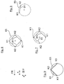
- Fig. 6 to 9 are shown simplistic replacement images that illustrate other variants of the torque transmitting element 61. Accordingly, according to the Fig. 6 not only a single coupling rod, but rather a total of up to four coupling rods may be provided, which are arranged circumferentially distributed around the wheel axle and are articulated to the wheel-side and axle-side coupling points K1 and K2.
- the coupling points K1 and K2 are all located on a circular line 65, which exemplarily reproduces the outer contour of a cardan ring of a universal joint, which is considerably more space-consuming than the coupling rods, as is shown by way of example in FIG DE 10 2009 058 489 A1 between the wheel-side support member and the axle-side guide member 17 is arranged.
- a total of three coupling rods 61 are provided, of which two coupling rods 61 extend in a straight line, while the third coupling rod 61, for example, due to space constraints has an S-shock.
- the torque transmitting element 61 is not formed by a coupling rod, but rather by coupling members, which can be claimed only on train, for example, chains or drawstrings.
Landscapes
- Engineering & Computer Science (AREA)
- Mechanical Engineering (AREA)
- Chemical & Material Sciences (AREA)
- Combustion & Propulsion (AREA)
- Transportation (AREA)
- Vehicle Body Suspensions (AREA)
- Braking Arrangements (AREA)
Claims (10)
- Dispositif de réglage du carrossage et/ou du pincement d'une roue de véhicule (13) d'un véhicule automobile, avec un support de roue (1), qui est construit en plusieurs parties avec une partie de support (3) côté roue et une partie de guidage (17) côté essieu ainsi qu'avec des parties rotatives (21, 23) agencées entre celles-ci et soutenues au niveau d'un point d'appui commun (31) de manière à pouvoir tourner l'une par rapport à l'autre autour d'un axe de rotation (24) autour duquel la partie rotative côté roue (21) peut pivoter autour d'un point d'oscillation (MP) afin de régler le carrossage ou le pincement de la roue de véhicule (13),
dans lequel la partie de support côté roue (3) porte un étrier de frein (15) qui coopère avec un disque de frein (11) de la roue de véhicule (13)
et dans lequel la partie de support côté roue (3) soumise à un couple de freinage lors d'une opération de freinage peut être soutenue sur la partie de guidage côté essieu (17) par l'intermédiaire d'un pont de couple (61),
lequel pont de couple (61) est conçu comme un élément de transfert de couple qui, lors du soutien de la partie de support (3) soumise au moment de freinage, produit une composante de force orientée (F) avec laquelle la partie de support côté roue (3) peut être sollicitée,
caractérisé en ce que l'élément de transfert de couple (61) est au moins une biellette de renvoi qui peut être sollicitée en traction et pression et en ce que la biellette de renvoi peut être articulée à chaque fois au niveau d'un point d'articulation côté roue (K2) au niveau de la partie de support côté roue (3) et au niveau d'un point d'articulation côté essieu (K1) au niveau de la partie de guidage côté essieu (17). - Dispositif selon la revendication 1, caractérisé en ce que les points d'articulation (K1, K2) de l'élément de transfert de couple (61) sont positionnés de telle sorte que l'élément de transfert de couple (61) peut être maté entre la partie de support (3) et la partie de guidage (17).
- Dispositif selon la revendication 1 ou 2, caractérisé en ce que, lors de l'opération de freinage, l'élément de transfert de couple (61) produit un couple en contrepoint (MKoppel) avec lequel peut être réduit le couple de réaction agissant de la roue de véhicule (13) sur les parties rotatives (21, 23) et résultant d'un couple total de roue de véhicule (MReifen).
- Dispositif selon la revendication 3, caractérisé en ce que le couple total de roue de véhicule (MReifen) se compose en particulier d'un couple longitudinal (MB,x), qui est produit par une composante longitudinale de force de freinage (FB,x) qui agit sur le centre de roue de véhicule (RM), et d'un couple vertical (MB,z), qui agit sur la roue de véhicule (13) et qui est produit par une compensation de tangage au freinage.
- Dispositif selon l'une quelconque des revendications précédentes, caractérisé en ce que le point central de roue (RM) de la roue de véhicule (13) et le point d'oscillation ou le centre instantané de rotation (MP) autour d'un arbre de levier sont à une certaine distance l'un de l'autre.
- Dispositif selon l'une quelconque des revendications précédentes, caractérisé en ce que les points d'articulation (K1, K2) de l'élément de transfert de couple (61) sont à une certaine distance du centre instantané de rotation (MP) dans les directions spatiales (x, y, z).
- Dispositif selon l'une quelconque des revendications précédentes, caractérisé en ce que les points d'articulation (K1, K2) de l'élément de transfert de couple (61) sont décalés, vus dans la direction transversale de véhicule (y), de distances (Δy1, Δy2) par rapport au centre instantané de rotation (MP) vers l'intérieur de véhicule et/ou en ce que les points d'articulation (K1, K2) sont positionnés, vus dans la direction longitudinale de véhicule (x), avant et après le centre instantané de rotation (MP) avec les distances (Δx1, Δx2) et/ou en ce que les points d'articulation (K1, K2) sont décalés de distances (Δz1, Δz2) par rapport au centre instantané de rotation (MP) dans la direction verticale de véhicule (z).
- Dispositif selon l'une quelconque des revendications précédentes, caractérisé en ce que dans la partie rotative côté roue (21) est intégré un palier de roue (12) dans lequel un tronçon de moyeu de roue (7) d'un boudin de roue (5) portant la roue de véhicule (13) est logé de manière à pouvoir tourner et/ou en ce que la partie de support (3) est appuyée sur la partie rotative côté roue (21) par l'intermédiaire d'un point d'appui (43).
- Dispositif selon la revendication 8, caractérisé en ce que la partie de support (3) est agencée radialement à l'extérieur de la partie rotative côté roue (21) et en ce que, en particulier, la partie de support (3) est appuyée sur la partie rotative côté roue (21) par l'intermédiaire d'un point d'appui (43) radialement à l'intérieur.
- Dispositif selon la revendication 8 ou 9, caractérisé en ce que le palier de roue (12) est réalisé démontable, à savoir avec un carter de palier radialement à l'intérieur et avec un carter de palier radialement à l'extérieur, qui est monté démontable, c'est-à-dire par exemple par ajustage serré ou par vissage, au niveau d'une circonférence extérieure du moyeu de roue (5) ou au niveau d'une circonférence intérieure de la partie rotative (21), ou en ce que la partie rotative côté roue (21) forme directement le carter de palier radialement extérieur du palier de roue (12), et en ce qu'une partie de moyeu de roue (7) d'un boudin de roue (5) portant la roue de véhicule (13) est montée de manière à pouvoir tourner radialement à l'intérieur de la partie rotative (21) formant le carter de palier extérieur.
Applications Claiming Priority (2)
| Application Number | Priority Date | Filing Date | Title |
|---|---|---|---|
| DE102014011110.5A DE102014011110B4 (de) | 2014-07-26 | 2014-07-26 | Vorrichtung zum Verstellen von Sturz und/oder Spur eines Fahrzeugrads mit Drehmomentübertragungselement |
| PCT/EP2015/001256 WO2016015801A1 (fr) | 2014-07-26 | 2015-06-22 | Dispositif de réglage du carrossage et/ou du pincement d'un véhicule à moteur |
Publications (2)
| Publication Number | Publication Date |
|---|---|
| EP3172071A1 EP3172071A1 (fr) | 2017-05-31 |
| EP3172071B1 true EP3172071B1 (fr) | 2018-06-06 |
Family
ID=53434297
Family Applications (1)
| Application Number | Title | Priority Date | Filing Date |
|---|---|---|---|
| EP15730067.4A Not-in-force EP3172071B1 (fr) | 2014-07-26 | 2015-06-22 | Dispositif de réglage du carrossage et/ou du pincement d'un véhicule à moteur |
Country Status (5)
| Country | Link |
|---|---|
| US (1) | US10286954B2 (fr) |
| EP (1) | EP3172071B1 (fr) |
| CN (1) | CN106573521B (fr) |
| DE (1) | DE102014011110B4 (fr) |
| WO (1) | WO2016015801A1 (fr) |
Families Citing this family (4)
| Publication number | Priority date | Publication date | Assignee | Title |
|---|---|---|---|---|
| DE102014011194B4 (de) * | 2014-07-26 | 2020-12-10 | Audi Ag | Radträger für ein zweispuriges Kraftfahrzeug mit Drehwinkelanschlägen für die Spur-/Sturzverstellung |
| DE102014011193B4 (de) * | 2014-07-26 | 2021-03-18 | Audi Ag | Vorrichtung zum Verstellen von Sturz und/oder Spur eines Fahrzeugrads mit einer Bremsmomentabstützung |
| WO2017018180A1 (fr) * | 2015-07-30 | 2017-02-02 | 本田技研工業株式会社 | Véhicule |
| US12187091B1 (en) * | 2023-12-07 | 2025-01-07 | Shock Therapy Suspension, Inc. | Upper control arm system |
Family Cites Families (31)
| Publication number | Priority date | Publication date | Assignee | Title |
|---|---|---|---|---|
| DE3928135A1 (de) * | 1988-08-31 | 1990-03-01 | Volkswagen Ag | Radaufhaengung fuer kraftfahrzeuge, insbesondere fuer personenkraftwagen |
| FR2872452B1 (fr) * | 2004-07-02 | 2006-09-22 | Michelin Soc Tech | Dispositif de suspension pour vehicule automobile |
| DE102004049296A1 (de) * | 2004-10-09 | 2006-04-13 | Bayerische Motoren Werke Ag | In einem Radträger gelagerte Nabeneinheit für ein Rad eines zweispurigen Fahrzeugs |
| DE102006061975B4 (de) * | 2006-12-21 | 2008-11-20 | Zf Friedrichshafen Ag | Radaufhängung |
| DE102008048567A1 (de) | 2008-09-23 | 2010-03-25 | Audi Ag | Vorrichtung zum Verstellen eines Rades einer Radaufhängung |
| DE102008048568A1 (de) * | 2008-09-23 | 2010-03-25 | Audi Ag | Lenkvorrichtung für ein Kraftfahrzeug |
| DE102009006903A1 (de) * | 2009-01-30 | 2010-08-05 | Audi Ag | Vorrichtung zum Verstellen von Sturz und/oder Spur der Räder von Radaufhängungen |
| DE102009021093A1 (de) * | 2009-05-13 | 2010-11-18 | Audi Ag | Radaufhängung für ein Kraftfahrzeug |
| DE102009021477A1 (de) | 2009-05-15 | 2010-11-18 | Audi Ag | Vorrichtung zum Verstellen von Sturz und/oder Spur |
| DE102009025227A1 (de) * | 2009-06-17 | 2010-12-30 | Audi Ag | Radaufhängung für die hinteren Räder von Kraftfahrzeugen |
| DE102009025586A1 (de) * | 2009-06-19 | 2010-12-23 | Audi Ag | Vorrichtung zum Verstellen von Sturz und/oder Spur der Räder einer Radaufhängung |
| DE102009038423A1 (de) | 2009-08-21 | 2011-03-10 | Audi Ag | Vorrichtung zum Verstellen von Sturz und/oder Spur |
| DE102009058490A1 (de) | 2009-12-16 | 2011-06-22 | Audi Ag, 85057 | Vorrichtung zum Verstellen von Sturz und/oder Spur der Räder von Radaufhängungen |
| DE102009058489A1 (de) * | 2009-12-16 | 2011-06-22 | Audi Ag, 85057 | Vorrichtung zum Verstellen von Sturz und/oder Spur der Räder von Kraftfahrzeugen |
| DE102010007994A1 (de) | 2010-02-15 | 2011-08-18 | Audi Ag, 85057 | Radaufhängung für ein Kraftfahrzeug |
| DE102010032073A1 (de) | 2010-07-23 | 2012-01-26 | Audi Ag | Verfahren zum Betreiben einer mechatronischen Fahrwerkeinrichtung eines Kraftfahrzeugs |
| DE102010050474B4 (de) | 2010-11-04 | 2013-05-08 | Audi Ag | Verfahren zur Bestimmung der Deichsellänge eines Anhängers eines Zugfahrzeuges sowie Verwendung dieses Verfahrens |
| DE102010052546A1 (de) | 2010-11-25 | 2012-05-31 | Audi Ag | Lenkeinrichtung |
| DE102011010509A1 (de) | 2011-02-07 | 2012-08-09 | Audi Ag | Fahrzeugrad |
| US20130099455A1 (en) | 2011-04-06 | 2013-04-25 | Audi Ag | Roll stabilizer for installation to a wheel suspension of a motor vehicle |
| DE102011016535B3 (de) | 2011-04-08 | 2012-05-10 | Audi Ag | Fahrzeugrad |
| DE102011111420B4 (de) | 2011-08-23 | 2015-11-19 | Audi Ag | Verfahren zur Steuerung lenkbarer Hinterräder eines Kraftfahrzeugs und Kraftfahrzeug |
| DE102012011918A1 (de) | 2012-06-15 | 2013-12-19 | Audi Ag | Verstellbare Radaufhängung für die Räder einer Achse eines Kraftfahrzeugs |
| DE102012011919A1 (de) | 2012-06-15 | 2013-12-19 | Audi Ag | Verstellbare Radaufhängung für die Räder einer Achse eines Kraftfahrzeugs |
| DE102012014696B4 (de) | 2012-07-25 | 2014-02-13 | Audi Ag | Dachträger für ein Kraftfahrzeug, Verfahren zum Betreiben eines Steuergeräts eines Kraftfahrzeugs sowie entsprechendes Steuergerät |
| DE102012020879B3 (de) | 2012-10-24 | 2014-03-13 | Audi Ag | Hydraulische Bremsanlage |
| DE102013002713B4 (de) | 2013-02-16 | 2014-08-28 | Audi Ag | Drehstabfederanordnung für eine Radaufhängung eines Kraftfahrzeugs |
| DE102013002714B4 (de) | 2013-02-16 | 2016-06-30 | Audi Ag | Drehfederanordnung für eine Radaufhängung eines Kraftfahrzeugs |
| DE102013008652B4 (de) * | 2013-05-21 | 2016-10-13 | Audi Ag | Vorrichtung zur Sturz- und/oder Spurverstellung eines Fahrzeugrades |
| DE102014009517B3 (de) | 2014-06-25 | 2015-09-17 | Audi Ag | Lenksystem |
| DE102014109038A1 (de) * | 2014-06-27 | 2015-12-31 | Benteler Automobiltechnik Gmbh | Radaufhängung |
-
2014
- 2014-07-26 DE DE102014011110.5A patent/DE102014011110B4/de not_active Expired - Fee Related
-
2015
- 2015-06-22 CN CN201580041271.4A patent/CN106573521B/zh not_active Expired - Fee Related
- 2015-06-22 EP EP15730067.4A patent/EP3172071B1/fr not_active Not-in-force
- 2015-06-22 US US15/329,171 patent/US10286954B2/en not_active Expired - Fee Related
- 2015-06-22 WO PCT/EP2015/001256 patent/WO2016015801A1/fr not_active Ceased
Non-Patent Citations (1)
| Title |
|---|
| None * |
Also Published As
| Publication number | Publication date |
|---|---|
| CN106573521A (zh) | 2017-04-19 |
| DE102014011110A1 (de) | 2016-01-28 |
| US20170217492A1 (en) | 2017-08-03 |
| US10286954B2 (en) | 2019-05-14 |
| EP3172071A1 (fr) | 2017-05-31 |
| WO2016015801A1 (fr) | 2016-02-04 |
| DE102014011110B4 (de) | 2021-03-18 |
| CN106573521B (zh) | 2019-05-17 |
Similar Documents
| Publication | Publication Date | Title |
|---|---|---|
| EP2342117B1 (fr) | Dispositif de direction pour un véhicule à moteur | |
| EP3122613B1 (fr) | Système de direction | |
| EP3172068B1 (fr) | Dispositif pour régler le carrossage et/ou parallélisme d'une roue d'un véhicule | |
| EP2467271B1 (fr) | Dispositif pour reglage du carrossage et/ou du pincement | |
| EP3172072B1 (fr) | Dispositif pour régler le carrossage et/ou parallélisme d'un roue d'un véhicule | |
| EP3172071B1 (fr) | Dispositif de réglage du carrossage et/ou du pincement d'un véhicule à moteur | |
| EP3216677B1 (fr) | Module de contre-rail pour véhicules automobiles comprenant une direction individuelle des roues | |
| EP2165862B1 (fr) | Dispositif de réglage d'une roue d'une suspension de roue | |
| EP3172069B1 (fr) | Dispositif pour régler le carrossage et/ou parallélisme d'un roue d'un véhicule | |
| EP2396183A1 (fr) | Suspension de roue pour véhicules automobiles présentant un élément de réglage associé au support de roue pour le réglage d'un angle de pincement et/ou de carrossage | |
| EP2558307B1 (fr) | Ensemble de roulement d'une roue motrice de véhicule | |
| WO2024064982A1 (fr) | Module de force de direction pour banc d'essai de chaîne cinématique | |
| DE102016223360B4 (de) | Antriebsanordnung für ein Fahrzeug sowie Fahrzeug mit der Antriebsanordnung | |
| DE2128356C3 (de) | Lenkeinrichtung für Fahrzeuge mit Ausregelung von Seitenkrafteinflüssen | |
| DE102017125605A1 (de) | Fahrwerk mit Friktionsbremseinrichtung sowie Fahrzeug mit dem Fahrwerk | |
| DE102015113156A1 (de) | Aktiver Radträger für ein Fahrzeug | |
| DE102014015062A1 (de) | Radaufhängung für ein zweispuriges Kraftfahrzeug | |
| DE102013022208A1 (de) | Lageranordnung zur Lagerung einer Radnabe, Kraftfahrzeug | |
| DE102010043298A1 (de) | Radaufhängung für einen rad-individuellen Antrieb von elektrisch angetriebenen Fahrzeugen |
Legal Events
| Date | Code | Title | Description |
|---|---|---|---|
| PUAI | Public reference made under article 153(3) epc to a published international application that has entered the european phase |
Free format text: ORIGINAL CODE: 0009012 |
|
| 17P | Request for examination filed |
Effective date: 20170227 |
|
| AK | Designated contracting states |
Kind code of ref document: A1 Designated state(s): AL AT BE BG CH CY CZ DE DK EE ES FI FR GB GR HR HU IE IS IT LI LT LU LV MC MK MT NL NO PL PT RO RS SE SI SK SM TR |
|
| AX | Request for extension of the european patent |
Extension state: BA ME |
|
| DAV | Request for validation of the european patent (deleted) | ||
| DAX | Request for extension of the european patent (deleted) | ||
| GRAP | Despatch of communication of intention to grant a patent |
Free format text: ORIGINAL CODE: EPIDOSNIGR1 |
|
| INTG | Intention to grant announced |
Effective date: 20180321 |
|
| GRAS | Grant fee paid |
Free format text: ORIGINAL CODE: EPIDOSNIGR3 |
|
| GRAA | (expected) grant |
Free format text: ORIGINAL CODE: 0009210 |
|
| AK | Designated contracting states |
Kind code of ref document: B1 Designated state(s): AL AT BE BG CH CY CZ DE DK EE ES FI FR GB GR HR HU IE IS IT LI LT LU LV MC MK MT NL NO PL PT RO RS SE SI SK SM TR |
|
| REG | Reference to a national code |
Ref country code: GB Ref legal event code: FG4D Free format text: NOT ENGLISH |
|
| REG | Reference to a national code |
Ref country code: CH Ref legal event code: EP Ref country code: AT Ref legal event code: REF Ref document number: 1005676 Country of ref document: AT Kind code of ref document: T Effective date: 20180615 |
|
| REG | Reference to a national code |
Ref country code: FR Ref legal event code: PLFP Year of fee payment: 4 |
|
| REG | Reference to a national code |
Ref country code: IE Ref legal event code: FG4D Free format text: LANGUAGE OF EP DOCUMENT: GERMAN |
|
| REG | Reference to a national code |
Ref country code: DE Ref legal event code: R096 Ref document number: 502015004560 Country of ref document: DE |
|
| REG | Reference to a national code |
Ref country code: NL Ref legal event code: MP Effective date: 20180606 |
|
| REG | Reference to a national code |
Ref country code: LT Ref legal event code: MG4D |
|
| PG25 | Lapsed in a contracting state [announced via postgrant information from national office to epo] |
Ref country code: NO Free format text: LAPSE BECAUSE OF FAILURE TO SUBMIT A TRANSLATION OF THE DESCRIPTION OR TO PAY THE FEE WITHIN THE PRESCRIBED TIME-LIMIT Effective date: 20180906 Ref country code: CY Free format text: LAPSE BECAUSE OF FAILURE TO SUBMIT A TRANSLATION OF THE DESCRIPTION OR TO PAY THE FEE WITHIN THE PRESCRIBED TIME-LIMIT Effective date: 20180606 Ref country code: FI Free format text: LAPSE BECAUSE OF FAILURE TO SUBMIT A TRANSLATION OF THE DESCRIPTION OR TO PAY THE FEE WITHIN THE PRESCRIBED TIME-LIMIT Effective date: 20180606 Ref country code: BG Free format text: LAPSE BECAUSE OF FAILURE TO SUBMIT A TRANSLATION OF THE DESCRIPTION OR TO PAY THE FEE WITHIN THE PRESCRIBED TIME-LIMIT Effective date: 20180906 Ref country code: SE Free format text: LAPSE BECAUSE OF FAILURE TO SUBMIT A TRANSLATION OF THE DESCRIPTION OR TO PAY THE FEE WITHIN THE PRESCRIBED TIME-LIMIT Effective date: 20180606 Ref country code: LT Free format text: LAPSE BECAUSE OF FAILURE TO SUBMIT A TRANSLATION OF THE DESCRIPTION OR TO PAY THE FEE WITHIN THE PRESCRIBED TIME-LIMIT Effective date: 20180606 Ref country code: ES Free format text: LAPSE BECAUSE OF FAILURE TO SUBMIT A TRANSLATION OF THE DESCRIPTION OR TO PAY THE FEE WITHIN THE PRESCRIBED TIME-LIMIT Effective date: 20180606 |
|
| PG25 | Lapsed in a contracting state [announced via postgrant information from national office to epo] |
Ref country code: HR Free format text: LAPSE BECAUSE OF FAILURE TO SUBMIT A TRANSLATION OF THE DESCRIPTION OR TO PAY THE FEE WITHIN THE PRESCRIBED TIME-LIMIT Effective date: 20180606 Ref country code: RS Free format text: LAPSE BECAUSE OF FAILURE TO SUBMIT A TRANSLATION OF THE DESCRIPTION OR TO PAY THE FEE WITHIN THE PRESCRIBED TIME-LIMIT Effective date: 20180606 Ref country code: LV Free format text: LAPSE BECAUSE OF FAILURE TO SUBMIT A TRANSLATION OF THE DESCRIPTION OR TO PAY THE FEE WITHIN THE PRESCRIBED TIME-LIMIT Effective date: 20180606 Ref country code: GR Free format text: LAPSE BECAUSE OF FAILURE TO SUBMIT A TRANSLATION OF THE DESCRIPTION OR TO PAY THE FEE WITHIN THE PRESCRIBED TIME-LIMIT Effective date: 20180907 |
|
| PG25 | Lapsed in a contracting state [announced via postgrant information from national office to epo] |
Ref country code: NL Free format text: LAPSE BECAUSE OF FAILURE TO SUBMIT A TRANSLATION OF THE DESCRIPTION OR TO PAY THE FEE WITHIN THE PRESCRIBED TIME-LIMIT Effective date: 20180606 |
|
| PG25 | Lapsed in a contracting state [announced via postgrant information from national office to epo] |
Ref country code: PL Free format text: LAPSE BECAUSE OF FAILURE TO SUBMIT A TRANSLATION OF THE DESCRIPTION OR TO PAY THE FEE WITHIN THE PRESCRIBED TIME-LIMIT Effective date: 20180606 Ref country code: EE Free format text: LAPSE BECAUSE OF FAILURE TO SUBMIT A TRANSLATION OF THE DESCRIPTION OR TO PAY THE FEE WITHIN THE PRESCRIBED TIME-LIMIT Effective date: 20180606 Ref country code: IS Free format text: LAPSE BECAUSE OF FAILURE TO SUBMIT A TRANSLATION OF THE DESCRIPTION OR TO PAY THE FEE WITHIN THE PRESCRIBED TIME-LIMIT Effective date: 20181006 Ref country code: RO Free format text: LAPSE BECAUSE OF FAILURE TO SUBMIT A TRANSLATION OF THE DESCRIPTION OR TO PAY THE FEE WITHIN THE PRESCRIBED TIME-LIMIT Effective date: 20180606 Ref country code: CZ Free format text: LAPSE BECAUSE OF FAILURE TO SUBMIT A TRANSLATION OF THE DESCRIPTION OR TO PAY THE FEE WITHIN THE PRESCRIBED TIME-LIMIT Effective date: 20180606 Ref country code: SK Free format text: LAPSE BECAUSE OF FAILURE TO SUBMIT A TRANSLATION OF THE DESCRIPTION OR TO PAY THE FEE WITHIN THE PRESCRIBED TIME-LIMIT Effective date: 20180606 |
|
| REG | Reference to a national code |
Ref country code: CH Ref legal event code: PL |
|
| PG25 | Lapsed in a contracting state [announced via postgrant information from national office to epo] |
Ref country code: SM Free format text: LAPSE BECAUSE OF FAILURE TO SUBMIT A TRANSLATION OF THE DESCRIPTION OR TO PAY THE FEE WITHIN THE PRESCRIBED TIME-LIMIT Effective date: 20180606 Ref country code: IT Free format text: LAPSE BECAUSE OF FAILURE TO SUBMIT A TRANSLATION OF THE DESCRIPTION OR TO PAY THE FEE WITHIN THE PRESCRIBED TIME-LIMIT Effective date: 20180606 |
|
| REG | Reference to a national code |
Ref country code: BE Ref legal event code: MM Effective date: 20180630 |
|
| REG | Reference to a national code |
Ref country code: DE Ref legal event code: R097 Ref document number: 502015004560 Country of ref document: DE |
|
| REG | Reference to a national code |
Ref country code: IE Ref legal event code: MM4A |
|
| PG25 | Lapsed in a contracting state [announced via postgrant information from national office to epo] |
Ref country code: MC Free format text: LAPSE BECAUSE OF FAILURE TO SUBMIT A TRANSLATION OF THE DESCRIPTION OR TO PAY THE FEE WITHIN THE PRESCRIBED TIME-LIMIT Effective date: 20180606 Ref country code: LU Free format text: LAPSE BECAUSE OF NON-PAYMENT OF DUE FEES Effective date: 20180622 |
|
| PLBE | No opposition filed within time limit |
Free format text: ORIGINAL CODE: 0009261 |
|
| STAA | Information on the status of an ep patent application or granted ep patent |
Free format text: STATUS: NO OPPOSITION FILED WITHIN TIME LIMIT |
|
| PG25 | Lapsed in a contracting state [announced via postgrant information from national office to epo] |
Ref country code: IE Free format text: LAPSE BECAUSE OF NON-PAYMENT OF DUE FEES Effective date: 20180622 Ref country code: LI Free format text: LAPSE BECAUSE OF NON-PAYMENT OF DUE FEES Effective date: 20180630 Ref country code: CH Free format text: LAPSE BECAUSE OF NON-PAYMENT OF DUE FEES Effective date: 20180630 |
|
| 26N | No opposition filed |
Effective date: 20190307 |
|
| PG25 | Lapsed in a contracting state [announced via postgrant information from national office to epo] |
Ref country code: SI Free format text: LAPSE BECAUSE OF FAILURE TO SUBMIT A TRANSLATION OF THE DESCRIPTION OR TO PAY THE FEE WITHIN THE PRESCRIBED TIME-LIMIT Effective date: 20180606 Ref country code: BE Free format text: LAPSE BECAUSE OF NON-PAYMENT OF DUE FEES Effective date: 20180630 Ref country code: DK Free format text: LAPSE BECAUSE OF FAILURE TO SUBMIT A TRANSLATION OF THE DESCRIPTION OR TO PAY THE FEE WITHIN THE PRESCRIBED TIME-LIMIT Effective date: 20180606 |
|
| PG25 | Lapsed in a contracting state [announced via postgrant information from national office to epo] |
Ref country code: AL Free format text: LAPSE BECAUSE OF FAILURE TO SUBMIT A TRANSLATION OF THE DESCRIPTION OR TO PAY THE FEE WITHIN THE PRESCRIBED TIME-LIMIT Effective date: 20180606 |
|
| PG25 | Lapsed in a contracting state [announced via postgrant information from national office to epo] |
Ref country code: MT Free format text: LAPSE BECAUSE OF FAILURE TO SUBMIT A TRANSLATION OF THE DESCRIPTION OR TO PAY THE FEE WITHIN THE PRESCRIBED TIME-LIMIT Effective date: 20180606 |
|
| PG25 | Lapsed in a contracting state [announced via postgrant information from national office to epo] |
Ref country code: TR Free format text: LAPSE BECAUSE OF FAILURE TO SUBMIT A TRANSLATION OF THE DESCRIPTION OR TO PAY THE FEE WITHIN THE PRESCRIBED TIME-LIMIT Effective date: 20180606 |
|
| PG25 | Lapsed in a contracting state [announced via postgrant information from national office to epo] |
Ref country code: PT Free format text: LAPSE BECAUSE OF FAILURE TO SUBMIT A TRANSLATION OF THE DESCRIPTION OR TO PAY THE FEE WITHIN THE PRESCRIBED TIME-LIMIT Effective date: 20180606 |
|
| PG25 | Lapsed in a contracting state [announced via postgrant information from national office to epo] |
Ref country code: MK Free format text: LAPSE BECAUSE OF NON-PAYMENT OF DUE FEES Effective date: 20180606 Ref country code: HU Free format text: LAPSE BECAUSE OF FAILURE TO SUBMIT A TRANSLATION OF THE DESCRIPTION OR TO PAY THE FEE WITHIN THE PRESCRIBED TIME-LIMIT; INVALID AB INITIO Effective date: 20150622 |
|
| PGFP | Annual fee paid to national office [announced via postgrant information from national office to epo] |
Ref country code: DE Payment date: 20210630 Year of fee payment: 7 Ref country code: FR Payment date: 20210630 Year of fee payment: 7 |
|
| REG | Reference to a national code |
Ref country code: AT Ref legal event code: MM01 Ref document number: 1005676 Country of ref document: AT Kind code of ref document: T Effective date: 20200622 |
|
| PGFP | Annual fee paid to national office [announced via postgrant information from national office to epo] |
Ref country code: GB Payment date: 20210624 Year of fee payment: 7 |
|
| PG25 | Lapsed in a contracting state [announced via postgrant information from national office to epo] |
Ref country code: AT Free format text: LAPSE BECAUSE OF NON-PAYMENT OF DUE FEES Effective date: 20200622 |
|
| REG | Reference to a national code |
Ref country code: DE Ref legal event code: R119 Ref document number: 502015004560 Country of ref document: DE |
|
| GBPC | Gb: european patent ceased through non-payment of renewal fee |
Effective date: 20220622 |
|
| PG25 | Lapsed in a contracting state [announced via postgrant information from national office to epo] |
Ref country code: FR Free format text: LAPSE BECAUSE OF NON-PAYMENT OF DUE FEES Effective date: 20220630 |
|
| PG25 | Lapsed in a contracting state [announced via postgrant information from national office to epo] |
Ref country code: GB Free format text: LAPSE BECAUSE OF NON-PAYMENT OF DUE FEES Effective date: 20220622 Ref country code: DE Free format text: LAPSE BECAUSE OF NON-PAYMENT OF DUE FEES Effective date: 20230103 |