EP3173577B1 - Vorrichtung zur visuellen untersuchung eines bohrlochs - Google Patents
Vorrichtung zur visuellen untersuchung eines bohrlochs Download PDFInfo
- Publication number
- EP3173577B1 EP3173577B1 EP16200501.1A EP16200501A EP3173577B1 EP 3173577 B1 EP3173577 B1 EP 3173577B1 EP 16200501 A EP16200501 A EP 16200501A EP 3173577 B1 EP3173577 B1 EP 3173577B1
- Authority
- EP
- European Patent Office
- Prior art keywords
- housing
- light source
- borehole
- transparent
- head
- Prior art date
- Legal status (The legal status is an assumption and is not a legal conclusion. Google has not performed a legal analysis and makes no representation as to the accuracy of the status listed.)
- Not-in-force
Links
- 150000001875 compounds Chemical class 0.000 claims description 12
- 238000007789 sealing Methods 0.000 claims description 12
- 239000000725 suspension Substances 0.000 claims description 12
- 239000012780 transparent material Substances 0.000 claims description 11
- 229910045601 alloy Inorganic materials 0.000 claims description 7
- 239000000956 alloy Substances 0.000 claims description 7
- 238000007689 inspection Methods 0.000 claims description 6
- 229910000851 Alloy steel Inorganic materials 0.000 claims description 5
- 238000005266 casting Methods 0.000 claims description 4
- 239000002131 composite material Substances 0.000 claims description 4
- 229910052751 metal Inorganic materials 0.000 claims description 4
- 239000002184 metal Substances 0.000 claims description 4
- 229920003229 poly(methyl methacrylate) Polymers 0.000 claims description 4
- 239000004926 polymethyl methacrylate Substances 0.000 claims description 4
- 239000011347 resin Substances 0.000 claims description 4
- 229920005989 resin Polymers 0.000 claims description 4
- VYPSYNLAJGMNEJ-UHFFFAOYSA-N Silicium dioxide Chemical compound O=[Si]=O VYPSYNLAJGMNEJ-UHFFFAOYSA-N 0.000 claims description 3
- 229910052910 alkali metal silicate Inorganic materials 0.000 claims description 3
- 239000005388 borosilicate glass Substances 0.000 claims description 3
- 239000005368 silicate glass Substances 0.000 claims description 3
- 239000004593 Epoxy Substances 0.000 claims description 2
- NIXOWILDQLNWCW-UHFFFAOYSA-N acrylic acid group Chemical group C(C=C)(=O)O NIXOWILDQLNWCW-UHFFFAOYSA-N 0.000 claims description 2
- 230000001154 acute effect Effects 0.000 claims description 2
- 229920001296 polysiloxane Polymers 0.000 claims description 2
- 229920002635 polyurethane Polymers 0.000 claims description 2
- 239000004814 polyurethane Substances 0.000 claims description 2
- 238000004382 potting Methods 0.000 description 11
- 239000000463 material Substances 0.000 description 9
- 238000011835 investigation Methods 0.000 description 7
- 239000011435 rock Substances 0.000 description 7
- 238000005286 illumination Methods 0.000 description 6
- 230000007797 corrosion Effects 0.000 description 5
- 238000005260 corrosion Methods 0.000 description 5
- 239000011521 glass Substances 0.000 description 5
- 230000000007 visual effect Effects 0.000 description 5
- TVTJUIAKQFIXCE-HUKYDQBMSA-N 2-amino-9-[(2R,3S,4S,5R)-4-fluoro-3-hydroxy-5-(hydroxymethyl)oxolan-2-yl]-7-prop-2-ynyl-1H-purine-6,8-dione Chemical compound NC=1NC(C=2N(C(N(C=2N=1)[C@@H]1O[C@@H]([C@H]([C@H]1O)F)CO)=O)CC#C)=O TVTJUIAKQFIXCE-HUKYDQBMSA-N 0.000 description 4
- PXHVJJICTQNCMI-UHFFFAOYSA-N Nickel Chemical compound [Ni] PXHVJJICTQNCMI-UHFFFAOYSA-N 0.000 description 4
- 229940125851 compound 27 Drugs 0.000 description 4
- 230000005540 biological transmission Effects 0.000 description 3
- 238000011157 data evaluation Methods 0.000 description 3
- 239000010935 stainless steel Substances 0.000 description 3
- 229910001220 stainless steel Inorganic materials 0.000 description 3
- VYZAMTAEIAYCRO-UHFFFAOYSA-N Chromium Chemical compound [Cr] VYZAMTAEIAYCRO-UHFFFAOYSA-N 0.000 description 2
- XEEYBQQBJWHFJM-UHFFFAOYSA-N Iron Chemical compound [Fe] XEEYBQQBJWHFJM-UHFFFAOYSA-N 0.000 description 2
- ZOKXTWBITQBERF-UHFFFAOYSA-N Molybdenum Chemical compound [Mo] ZOKXTWBITQBERF-UHFFFAOYSA-N 0.000 description 2
- 229910000831 Steel Inorganic materials 0.000 description 2
- 229910052804 chromium Inorganic materials 0.000 description 2
- 239000011651 chromium Substances 0.000 description 2
- 238000005336 cracking Methods 0.000 description 2
- 239000007788 liquid Substances 0.000 description 2
- 239000000203 mixture Substances 0.000 description 2
- 229910052750 molybdenum Inorganic materials 0.000 description 2
- 239000011733 molybdenum Substances 0.000 description 2
- 229910052759 nickel Inorganic materials 0.000 description 2
- 230000003287 optical effect Effects 0.000 description 2
- 230000008439 repair process Effects 0.000 description 2
- 239000000523 sample Substances 0.000 description 2
- 239000010959 steel Substances 0.000 description 2
- VEXZGXHMUGYJMC-UHFFFAOYSA-M Chloride anion Chemical compound [Cl-] VEXZGXHMUGYJMC-UHFFFAOYSA-M 0.000 description 1
- 229910000990 Ni alloy Inorganic materials 0.000 description 1
- 239000002253 acid Substances 0.000 description 1
- 150000007513 acids Chemical class 0.000 description 1
- 238000013016 damping Methods 0.000 description 1
- 238000013500 data storage Methods 0.000 description 1
- 230000001419 dependent effect Effects 0.000 description 1
- 238000005265 energy consumption Methods 0.000 description 1
- 238000011156 evaluation Methods 0.000 description 1
- 239000000835 fiber Substances 0.000 description 1
- 230000006870 function Effects 0.000 description 1
- 238000003780 insertion Methods 0.000 description 1
- 230000037431 insertion Effects 0.000 description 1
- 229910052742 iron Inorganic materials 0.000 description 1
- 230000001590 oxidative effect Effects 0.000 description 1
- 239000004033 plastic Substances 0.000 description 1
- 229920003023 plastic Polymers 0.000 description 1
- 238000002360 preparation method Methods 0.000 description 1
- 238000001454 recorded image Methods 0.000 description 1
- 239000007787 solid Substances 0.000 description 1
- 238000003860 storage Methods 0.000 description 1
- WFKWXMTUELFFGS-UHFFFAOYSA-N tungsten Chemical compound [W] WFKWXMTUELFFGS-UHFFFAOYSA-N 0.000 description 1
- 229910052721 tungsten Inorganic materials 0.000 description 1
- 239000010937 tungsten Substances 0.000 description 1
- 238000011179 visual inspection Methods 0.000 description 1
- 229910000859 α-Fe Inorganic materials 0.000 description 1
Images


Classifications
-
- E—FIXED CONSTRUCTIONS
- E21—EARTH OR ROCK DRILLING; MINING
- E21B—EARTH OR ROCK DRILLING; OBTAINING OIL, GAS, WATER, SOLUBLE OR MELTABLE MATERIALS OR A SLURRY OF MINERALS FROM WELLS
- E21B47/00—Survey of boreholes or wells
- E21B47/002—Survey of boreholes or wells by visual inspection
Definitions
- the invention relates to a device according to the preamble of claim 1.
- a device In the visual examination of boreholes, a device is guided into a borehole, which is intended to illuminate the inside of the borehole on the one hand by means of a light source and, on the other hand, to visually detect it.
- a light source In this case, either images and / or video recordings of the inside of the borehole are recorded, which are either stored in a storage medium or sent directly (live) to a playback device.
- a device of this kind is from the DE 10 2012 223 458 A1 known, wherein a video probe for the inspection of boreholes is disclosed.
- the video probe comprises a housing in which a video camera, an image memory, a power source and a light source are accommodated.
- the housing is pressure-sealed with a lid, wherein the lid has fastening means for attaching a rope.
- the housing has a removable window component, which can be screwed to the housing, wherein the window component is made of glass or acrylic glass. Behind the window component, inside the housing, the light source and the camera are arranged, wherein the light source emits light in the direction of the field of view of the camera, through the window component.
- the reflector has an elliptical shape and focuses the light emitted by the light source in a focal point.
- a light guide which is arranged in the focal point, directs the light to a distal end of the housing, on which a camera is arranged.
- a lens is arranged, which aligns the light in the direction of the field of view of the camera.
- the US 2013/0287380 A1 discloses an optical element for a downhole camera having an inner region and an outer region, the cylindrical contact surface of which is configured in such a way is that no light can transmit from one area to the other area.
- the optical element is arranged on a plate which has a central passage opening, around which the further passage openings are arranged in a circle.
- Light sources are disposed in the through holes, and a lens of a camera is disposed in the central through hole.
- the US 2015/077537 A1 shows a camera system, with a camera and a light source, which are arranged in a housing.
- the housing has a conical front part, which has a viewing window, on the inside of which an end region of a lens rests.
- the lens is connected at its other end to an image sensor of the camera.
- the front part Circumferentially around the viewing window of the lens, the front part further openings, which are sealed with a glass.
- Behind it light sources are arranged, wherein the openings are preferably arranged at an angle to the main axis of the housing.
- a disadvantage of the devices disclosed in the prior art is the fact that the light source is arranged inside or behind a transparent element, whereby the light emitted by the light source on the inside of the transparent element is partially reflected towards the camera. As a result, the quality of the recorded images is degraded because the reflected or reflected light blends the lens of the camera. As a result, the recorded data can usually become unusable or not evaluable.
- the window element consists of a transparent solid body made of plastic or glass, which is damaged when moving the device in the borehole more due to projecting rock elements or the like in a relatively simple manner. If the window element has cracked, no meaningful recordings of the borehole can be taken disadvantageously with the device, so that considerable time and cost is lost in preparation for the investigation of the borehole. In addition to the costly repair or the purchase of a new device Therefore, the investigation of the borehole usually has to be repeated, which leads to a considerable increase in the costs.
- the object of the present invention is to eliminate or at least mitigate at least individual disadvantages of the prior art.
- the invention is therefore particularly aimed at providing a device for the investigation of a borehole, with which a uniform and sufficiently bright illumination of the borehole takes place, so that reliable images can be taken in a quality enabling an analysis of the borehole.
- the risk of damage to the viewing window is to be reduced.
- the device head consists essentially of an intransparent material in which a preferably circular central viewing window made of a transparent material is accommodated, the device head having in the non-transparent material at least one passage opening which is laterally spaced from the viewing window and in which at least one light source is recorded.
- the device according to the invention comprises a housing which has a camera, an electronics unit and a power supply unit, wherein the housing is preferably cylindrical in shape due to the shape of a borehole.
- the housing is made of a pressure resistant material which withstands physical conditions within a wellbore .
- the power supply unit is preferably a battery, with which the electronics unit and the camera are supplied with energy.
- the electronics unit is in particular provided to control the functions of the camera and the light source and to store the acquired data or directly to to send a data evaluation unit outside the borehole.
- the data transmission can preferably be done with a cable or wirelessly.
- the housing has a suspension device on which preferably a cable, a wire and / or a corresponding cable, for example a fiber optic cable, are arranged for data transmission.
- a suspension device on which preferably a cable, a wire and / or a corresponding cable, for example a fiber optic cable, are arranged for data transmission.
- the cable for data transmission is preferably connected at one end to the device and at the other end to a data evaluation unit which stores, analyzes and reproduces the data recorded by the camera.
- the device can in particular also be supplied with power with the cable, as a result of which the power supply unit can be dispensed with.
- the housing has at the opposite end to a device head, which made of an opaque material and having a transparent material consisting of, preferably circular, central viewing window.
- the viewing window is therefore circumferentially of the non-transparent material at least partially, preferably fully enclosed. If the device when moving in the borehole, in particular when lowering the device laterally abuts or abuts the rock surrounding the borehole, the viewing window advantageously does not come into contact with the possibly pointed projections having rock. Thus, the risk of damage to the viewing window can be significantly reduced.
- the viewing window is located substantially in the field of view of the camera so that image data can be captured from the inside of the borehole.
- the device head additionally has at least one passage opening, which is laterally spaced from the viewing window and in which at least one light source is accommodated.
- the through-hole is therefore advantageously formed in the manner of a channel enclosed in the intransparent material of the device head.
- the arrangement of the light source in a separate passage opening in the non-transparent device head unwanted scattering of the light, whereby unwanted reflections can be effected, can be avoided.
- the light emitted by the light source passes through thus directed the device head, whereby a precise illumination of the borehole and subsequently a high quality image acquisition is possible.
- the camera may be disposed in the device head.
- the device head is substantially formed as a separate element from the housing, which is preferably connectable to the housing by means of a screw connection.
- sealing elements may be provided to ensure a tight connection between the device head and the housing.
- the preferably sealed with sealing elements screw connection between the device head and the housing, the components of the device are protected by the physical conditions within the borehole.
- the device head is integrally formed with the housing.
- the passage opening in particular at least a portion of the longitudinal extent of the passage opening, which has no light source, preferably completely filled with a transparent potting compound.
- the passage opening is closed and sealed, at the same time a directed passage of light is made possible.
- the light source is fixed with a transparent potting compound in a portion of the longitudinal extent of the passage opening.
- the non-transparent material preferably has a higher breaking strength, in particular a higher one Compressive strength, as the transparent potting compound.
- a metal, an alloy or a composite material, in particular a steel alloy is provided as the intransparent material. Materials of this type are characterized by a high breaking strength and can withstand the physical conditions inside the borehole.
- the transparent potting compound is a casting resin, in particular a one- or more-component casting resin based on epoxy, polyurethane, acrylic or silicone.
- the advantage of a potting compound is that it can be easily processed in a liquid state.
- the passage opening in the device head is substantially filled with liquid potting compound, which closes the passage opening after curing, seals and protects the light source against mechanical stress, temperature, pressure, dirt and the like. Due to the transparency of the potting compound, the light of the light source can be radiated into the interior of the borehole.
- the central viewing window consists of a transparent alkali silicate glass, acrylic glass, borosilicate glass or quartz glass. Glasses of this type have the advantage that they are mechanically strong and thus can be used inside the borehole. The exact composition of the glass used and its thickness is preferably to be selected according to the physical conditions inside the borehole.
- a light source in particular a light-emitting diode
- each passage opening is accommodated in each passage opening.
- this preferred arrangement of the light sources minimizes the amount of reflected light since each light source is fixed in a separate through hole in the non-transparent device head with a transparent potting compound.
- the light source arrangement is advantageously spatially separated from the camera by an intransparent material and the light is thus emitted in a predetermined direction.
- the individual light sources are preferably arranged in separate holding elements, wherein in each case a holding element is arranged in a passage opening.
- the holding member is fixed in the through hole with a tight screw connection and has at one end a transparent lens which focuses the light emitted from the light sources in an excellent direction.
- the holding elements are each separately removable from the device head, so that the replacement of individual LEDs can be done very easily.
- the longitudinal axis of the passage opening in each case at an acute angle ⁇ , preferably between 15 ° and 35 °, to the longitudinal axis of the housing arranged.
- ⁇ preferably between 15 ° and 35 °
- the light is radiated at an angle to the longitudinal axis of the housing, whereby the illumination of the borehole is laterally improved by the device. Since the visual inspection specifically targets the inside of the borehole, illumination from the side of the device is particularly advantageous.
- a light-emitting diode is preferably provided as a light source. Due to the small size of LEDs, a plurality of LEDs, preferably three to twelve, are arranged in an equal number of through holes in the device head. This increases the luminosity and thus improves the wellbore illumination, the size of the device being small enough to be routed into the wellbore.
- a detachable connection preferably a screw connection with at least one sealing element, is provided between the suspension device and the housing.
- the connection can be designed analogously to the screw connection between the housing and the device head.
- the suspension device and the housing are integrally formed.
- the power supply is provided in the housing for powering the light source in the device head, a conductive contact being closed when the housing and device head are connected together, preferably with a spring disposed between the camera and the electronics unit. Due to the additional force of the spring, the contact, while the device head and the housing are engaged with each other, remains upright even under mechanical loads. In addition, a possible movement of the individual components within the housing is damped by the spring, whereby it does not cause any damage within the housing during abrupt changes in the movement of the device comes through an uncontrolled movement of the components.
- the power supply is carried out with a cable which is guided into the borehole together with the rope on which the device is suspended. This ensures a battery-independent power supply.
- the suspension device and the housing essentially consist of a metal, an alloy or a composite material. Materials of this type are characterized by high mechanical strength and are therefore ideal for use in the interior of a borehole.
- the visually acquired data of the camera are preferably stored in a data memory, which is arranged within the device, in particular within the camera, wherein the stored data at a later time after the investigation of the borehole is completed, are evaluated.
- the image and / or video data is sent directly (live) to a playback device. This can be done with a suitable cable or wirelessly. In this embodiment can be dispensed with an additional data storage.
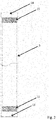
- Fig. 1 shows a device 1 for the visual examination of a borehole 22 (see. Fig. 8 ), which has a camera 2, an electronic unit 3 and a power supply unit 4.
- the electronic unit 3 and a power supply unit 4 are arranged in a pressure-resistant, cylindrical housing 5, the device 1 having at one end a suspension device 6 and at one opposite end a flameproof cylindrical device head 8 comprising a viewing window 7.
- the device head 8 is made of a steel alloy, in particular of a corrosion-resistant austenitic-ferritic steel or a nickel alloy, preferably stainless steel W-No. 1.4462 or the highly corrosion-resistant nickel-based alloy W-No. 2.4602, ie an opaque material, in which passage openings 10 are provided, which are laterally spaced from the viewing window 7.
- Stainless steel W-No. 1.4462 is an austenitic-ferritic steel with essentially 40-50% ferrite and a high resistance in media containing chloride. Due to the high total content of chromium and molybdenum, this stainless steel has a very good pitting resistance and high resistance to stress corrosion cracking and vibration cracking corrosion.
- the nickel-based alloy W-No. 2.4602 features by the addition of chromium, molybdenum, tungsten and a controlled iron content with excellent resistance to oxidizing, reducing and mixed acids.
- the alloy is also very resistant to pitting and crevice corrosion, especially in an acid-halide climate.
- the device head 8 can be connected to the housing 5 via a screw connection 11 which has sealing elements 12.
- a spring 26 is arranged between the camera 2 and the electronic unit 3 and / or between the electronic unit 3 and the power supply unit 4.
- the spring 26 serves as a damping unit to protect the individual components within the housing 5 against possible damage. Abrupt changes in the movement of the device 1 may lead to collisions of the individual components which are arranged within the housing 5. By the spring 26 unwanted movements of the components are damped, whereby damage due to collisions are avoided.
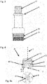
- Fig. 2 shows the housing 5, wherein at a first end 13 via the screw 11 of the device head 8 can be arranged and at a second end 14 via a further screw 15, the suspension device 6 can be arranged.
- Fig. 3 shows the suspension device 6, which via the screw 15, which sealing elements 16, with the housing 5 is connectable (see. Fig. 1 ).
- a connecting element 17 is arranged, on which a cable and / or a cable (not shown) can be arranged.
- the through holes 10 are arranged at an angle ⁇ of about 15 ° to 20 ° to the longitudinal axis x of the device 1.
- a light source 9 is arranged in a transparent potting compound 27.
- the device head 8 has an outer cylindrical shell of the relatively break-resistant steel alloy, so that at a possible (lateral) striking the device head 8, in particular when lowering the device 1 in the borehole 22, on rock elements or other sharp-edged projections only of the steel alloy existing device head 8 comes in touching contact with any projections in the borehole 22.
- the viewing window 7 and the sealing compound 27 received in the passage opening 10 are thus protected by the device head 8 which surrounds it, so that the risk of damage to the transparent materials is extremely low.
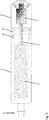
- Fig. 5 shows an alternative embodiment of the device 1, wherein the camera 2 is disposed within the device head 8.
- Fig. 6 shows a detailed view of the device head 8.
- the light sources 9 are in turn arranged in each case in a passage opening 10.
- the passage openings 10 are not filled with a transparent potting compound 27, as in the embodiment according to the Figures 1 to 4a but the passage openings 10 are provided with closure elements 18, which are each connected by means of a screw connection with the passage opening 10.
- closure elements 18 have an outer nut-like threaded portion 18 'with a central opening, in which a transparent viewing window 18'', preferably made of an alkali silicate glass, acrylic glass, borosilicate glass or quartz glass, is added.
- the through-openings 10 can thus be closed in a pressure-tight manner in a particularly simple manner, compared to a pressure-tight closing of the through-openings 10 with a transparent potting compound 27, as in the embodiment according to FIGS Figures 1 to 4a
- these windows 18 have a larger footprint, so that they can be used in particular in devices 1 with an outer diameter greater than 70mm, eg 90mm.
- the viewing window 7 is accommodated in a substantially identically constructed, central closure element 20 of larger diameter.
- the device head 8 is analogous to the embodiment according to Figures 1 to 4a via a screw 11, which has sealing elements 12, connected to the housing 5.
- Fig. 7 shows a plan view of the device head 8 of the alternative embodiment according to Fig. 5 and 6 ,
- the holding elements 18 are arranged at equidistant intervals around the viewing window 7, which in turn is accommodated in a further holding element 20.
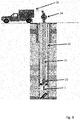
- Fig. 8 shows schematically the course of a borehole investigation.
- the device 1 is guided on a rope 21 in a borehole 22, wherein a centralizer 23 ensures a uniform distance of the device 1 to the inside of the borehole 22.
- the vertical depth of the device 1 is controlled by a winch 24.
- the evaluation of the visual data recorded during the borehole examination is carried out with a data evaluation unit 25.
Landscapes
- Physics & Mathematics (AREA)
- Life Sciences & Earth Sciences (AREA)
- Engineering & Computer Science (AREA)
- Geology (AREA)
- Mining & Mineral Resources (AREA)
- Geophysics (AREA)
- Environmental & Geological Engineering (AREA)
- Fluid Mechanics (AREA)
- General Life Sciences & Earth Sciences (AREA)
- Geochemistry & Mineralogy (AREA)
- Investigating Materials By The Use Of Optical Means Adapted For Particular Applications (AREA)
Description
- Die Erfindung betrifft eine Vorrichtung gemäß dem Oberbegriff von Anspruch 1.
- Bei der visuellen Untersuchung von Bohrlöchern wird eine Vorrichtung in ein Bohrloch geführt, welche dazu vorgesehen ist, die Innenseite des Bohrlochs einerseits mit Hilfe einer Lichtquelle auszuleuchten und andererseits visuell zu erfassen. Dabei werden entweder Bilder und/oder Videoaufnahmen von der Innenseite des Bohrlochs aufgenommen, die entweder in einem Speichermedium gespeichert oder direkt (live) an eine Wiedergabevorrichtung gesendet werden.
- Eine Vorrichtung dieser Art ist aus der
DE 10 2012 223 458 A1 bekannt, wobei eine Videosonde zur Inspektion von Bohrlöchern offenbart wird. Die Videosonde umfasst ein Gehäuse, in welchem eine Videokamera, ein Bildspeicher, eine Stromquelle und eine Lichtquelle aufgenommen sind. An einem Ende ist das Gehäuse mit einem Deckel druckdicht verschlossen, wobei der Deckel Befestigungsmittel zur Befestigung eines Seils aufweist. An dem anderen Ende weist das Gehäuse ein abnehmbares Fensterbauteil auf, welches mit dem Gehäuse verschraubbar ist, wobei das Fensterbauteil aus Glas oder Acrylglas gefertigt ist. Hinter dem Fensterbauteil, im Inneren des Gehäuses, sind die Lichtquelle und die Kamera angeordnet, wobei die Lichtquelle Licht in Richtung des Blickfelds der Kamera, durch das Fensterbauteil, abstrahlt. - Weiters offenbart die
DE 601 30 558 T2 ein Untersuchungsinstrument zur Einführung in ein Bohrloch, bei welchem eine Kamera, eine Lichtquelle und ein Reflektor in einem Gehäuse angeordnet sind. Der Reflektor hat eine elliptische Form und fokussiert das von der Lichtquelle abgestrahlt Licht in einem Brennpunkt. Ein Lichtleiter, welcher in dem Brennpunkt angeordnet ist, leitet das Licht an ein distales Ende des Gehäuses, an welchem eine Kamera angeordnet ist. Am Ende des Lichtleiters ist eine Linse angeordnet, die das Licht in Richtung des Blickfelds der Kamera ausrichtet. - Die
US 2013/0287380 A1 offenbart ein optisches Element für eine Bohrlochkamera, mit einem inneren Bereich und einem äußeren Bereich, wobei deren zylinderförmige Kontaktfläche derart ausgestaltet ist, dass kein Licht von einem Bereich in den anderen Bereich transmittieren kann. Das optische Element ist auf einer Platte angeordnet, welche eine zentrale Durchgangsöffnung aufweist, um die weitere Durchgangsöffnungen kreisförmig angeordnet sind. Lichtquellen sind in den Durchgangsöffnungen angeordnet, und eine Linse einer Kamera ist in der zentralen Durchgangsöffnung angeordnet. - Die
US 2015/077537 A1 zeigt ein Kamerasystem, mit einer Kamera und einer Lichtquelle, welche in einem Gehäuse angeordnet sind. An einem Ende weist das Gehäuses einen konischen Vorderteil auf, welcher ein Sichtfenster aufweist, an dessen Innenseite ein Endbereich einer Linse anliegt. Die Linse ist an ihrem anderen Ende mit einem Bildsensor der Kamera verbunden. Kreisrund um das Sichtfenster der Linse weist der Vorderteil weitere Öffnungen auf, welche mit einem Glas abgedichtet sind. Dahinter sind Lichtquellen angeordnet, wobei die Öffnungen bevorzugt in einem Winkel zur Hauptachse des Gehäuses angeordnet sind. - Ein Nachteil der im Stand der Technik offenbarten Vorrichtungen ist die Tatsache, dass die Lichtquelle im Inneren oder hinter einem transparenten Element angeordnet ist, wodurch das von der Lichtquelle abgestrahlte Licht an der Innenseite des transparenten Elements teilweise in Richtung der Kamera reflektiert wird. Dadurch wird die Qualität der aufgenommenen Bilder verschlechtert, da das reflektierte bzw. rückgestrahlte Licht die Linse der Kamera überblendet. Dadurch können die aufgezeichneten Daten meist unbrauchbar bzw. nicht auswertbar werden.
- Ein weiterer Nachteil bei der Ausgestaltung gemäß der
DE 10 2012 223 458 A1 ist zudem, dass das Fensterelement aus einem transparenten Vollkörper aus Kunststoff oder Glas besteht, welcher beim Bewegen der Vorrichtung im Bohrloch mehr aufgrund vorspringender Gesteinselemente oder dergleichen auf vergleichsweise einfache Weise beschädigt wird. Sofern das Fensterelement gesprungen ist, können nachteiliger Weise mit der Vorrichtung keine aussagekräftigen Aufnahmen des Bohrlochs aufgenommen werden, so dass erheblicher Zeit- und Kostenaufwand zu Vorbereitung der Untersuchung des Bohrlochs verloren geht. Zusätzlich zu der mit Kosten verbundenen Reparatur oder der Anschaffung einer neuen Vorrichtung muss meist daher auch die Untersuchung des Bohrlochs wiederholt werden, was zu einer erheblichen Erhöhung der Kosten führt. - Demnach besteht die Aufgabe der vorliegenden Erfindung darin, zumindest einzelne Nachteile des Standes der Technik zu beseitigen oder zumindest zu lindern. Die Erfindung setzt sich daher insbesondere zum Ziel, eine Vorrichtung zur Untersuchung eines Bohrlochs zu schaffen, mit welcher eine gleichmäßige und ausreichend helle Ausleuchtung des Bohrlochs erfolgt, so dass zuverlässig Bilder in einer eine Analyse des Bohrlochs ermöglichenden Qualität aufgenommen werden können. Zusätzlich soll das Risiko einer Beschädigung des Sichtfensters verringert werden.
- Diese Aufgabe wird durch eine Vorrichtung mit den Merkmalen von Anspruch 1 gelöst. Bevorzugte Ausführungsformen sind in den abhängigen Ansprüchen angegeben.
- Erfindungsgemäß ist vorgesehen, dass der Vorrichtungskopf im Wesentlichen aus einem intransparenten Material besteht, in welchem ein aus einem transparenten Material bestehendes vorzugsweise kreisförmiges zentrales Sichtfenster aufgenommen ist, wobei der Vorrichtungskopf in dem intransparenten Material zumindest eine Durchgangsöffnung aufweist, welche von dem Sichtfenster seitlich beabstandet ist und in welcher zumindest eine Lichtquelle aufgenommen ist.
- Die erfindungsgemäße Vorrichtung umfasst ein Gehäuse, welches eine Kamera, eine Elektronikeinheit und eine Stromversorgungseinheit aufweist, wobei das Gehäuse aufgrund der Form eines Bohrlochs vorzugsweise zylinderförmig ausgestaltet ist. Um die Kamera, die Elektronikeinheit und die Stromversorgungseinheit gegen die physikalischen Bedingungen (hohe Temperatur, hoher Druck, Schmutz, Gestein, etc.) in dem Bohrloch zu schützen, ist das Gehäuse aus einem druckfesten Material gefertigt, welches den physikalischen Bedingungen innerhalb eines Bohrlochs standhält. Die Stromversorgungseinheit ist vorzugsweise eine Batterie, mit welcher die Elektronikeinheit und die Kamera mit Energie versorgt werden. Die Elektronikeinheit ist insbesondere dazu vorgesehen, die Funktionen der Kamera und die Lichtquelle zu steuern und die erfassten Daten zu speichern oder direkt an eine Datenauswertungseinheit außerhalb des Bohrlochs zu senden. Die Datenübertragung kann vorzugsweise mit einem Kabel oder kabellos erfolgen. An einem Ende weist das Gehäuse eine Aufhängevorrichtung auf, an welcher vorzugsweise ein Seil, ein Draht und/oder ein entsprechendes Kabel, beispielsweise ein Glasfaserkabel, zur Datenübertragung angeordnet sind. Mit dem Seil kann die Vorrichtung kontrolliert in das Innere des Bohrlochs hinab gelassen werden und nach Beendigung der Untersuchung wieder sicher aus dem Bohrloch entfernt werden. Das Kabel zur Datenübertragung ist vorzugsweise an einem Ende mit der Vorrichtung und am anderen Ende mit einer Datenauswertungseinheit verbunden, welche die von der Kamera aufgenommenen Daten speichert, auswertet und wiedergibt. In einer alternativen Ausführungsform kann mit dem Kabel die Vorrichtung insbesondere auch mit Strom versorgt werden, wodurch auf die Stromversorgungseinheit verzichtet werden kann. Das Gehäuse weist am gegenüberliegenden Ende einen Vorrichtungskopf auf, welcher aus einem intransparenten Material gefertigt und ein aus einem transparenten Material bestehendes, vorzugsweise kreisförmiges, zentrales Sichtfenster aufweist. Das Sichtfenster ist demnach umfangseitig von dem intransparenten Material zumindest abschnittsweise, vorzugsweise vollumfänglich, eingefasst. Sofern die Vorrichtung beim Bewegen im Bohrloch, insbesondere beim Herablassen der Vorrichtung seitlich an dem das Bohrloch umschließende Gestein anstößt bzw. anschlägt, kommt das Sichtfenster vorteilhafterweise nicht mit dem allenfalls spitze Vorsprünge aufweisenden Gestein in Kontakt. Somit kann das Risiko einer Beschädigung des Sichtfensters erheblich reduziert werden. Das Sichtfenster ist im Wesentlichen im Blickfeld der Kamera angeordnet, sodass Bilddaten von der Innenseite des Bohrlochs erfasst werden können. Der Vorrichtungskopf weist zusätzlich zumindest eine Durchgangsöffnung auf, welche von dem Sichtfenster seitlich beabstandet ist und in welcher zumindest eine Lichtquelle aufgenommen ist. Die Durchgangsöffnung ist daher vorteilhafterweise in der Art eines umseitig eingeschlossenen Kanals in dem intransparenten Material des Vorrichtungskopfs ausgebildet. Vorteilhafterweise kann durch die Anordnung der Lichtquelle in einer separaten Durchgangsöffnung in dem intransparenten Vorrichtungskopf eine ungewollte Streuung des Lichts, wodurch auch ungewollte Reflexionen bewirkt werden können, vermieden werden. Das von der Lichtquelle abgestrahlte Licht durchsetzt somit gerichtet den Vorrichtungskopf, womit eine präzise Ausleuchtung des Bohrlochs und in weiterer Folge eine hochqualitative Bildaufnahme ermöglicht wird. In einer alternativen Ausführungsform kann die Kamera in dem Vorrichtungskopf angeordnet sein.
- In einer bevorzugten Ausführungsform ist der Vorrichtungskopf im Wesentlichen als ein vom Gehäuse gesondertes Element ausgebildet, welches mit dem Gehäuse vorzugsweise mittels einer Schraubverbindung verbindbar ist. Zusätzlich können Dichtelemente vorgesehen sein, um eine dichte Verbindung zwischen dem Vorrichtungskopf und dem Gehäuse zu gewährleisten. Bei dieser Ausführungsform ergibt sich der Vorteil, dass der Vorrichtungskopf einfach und rasch von dem Gehäuse trennbar ist, wodurch Reparaturen oder der Austausch von Komponenten vereinfacht werden. Durch die vorzugsweise mit Dichtelementen abgedichtete Schraubverbindung zwischen dem Vorrichtungskopf und dem Gehäuse werden die Komponenten der Vorrichtung von den physikalischen Bedingungen innerhalb des Bohrlochs geschützt. In einer weiteren Ausführungsform ist der Vorrichtungskopf mit dem Gehäuse einteilig ausgebildet.
- In einer bevorzugten Ausführungsform ist insbesondere zumindest ein Abschnitt der Längsausdehnung der Durchgangsöffnung, welcher keine Lichtquelle aufweist, vorzugsweise vollständig mit einer transparenten Vergussmasse ausgefüllt. Damit wird die Durchgangsöffnung verschlossen und abgedichtet, wobei zugleich ein gerichteter Lichtdurchtritt ermöglicht wird.
- Hinsichtlich einer einfachen und zuverlässigen Befestigung der Lichtquelle in der jeweiligen Durchgangsöffnung ist erfindungsgemäß vorgesehen, dass die Lichtquelle mit einer transparenten Vergussmasse in einem Abschnitt der Längsausdehnung der Durchgangsöffnung fixiert ist.
- Um die Vorrichtung gegen die physikalischen Bedingungen im Inneren des Bohrlochs zu schützen und damit die Funktionalität der Vorrichtung zu gewährleisten, weist das intransparente Material bevorzugt eine höhere Bruchfestigkeit, insbesondere eine höherer Druckfestigkeit, als die transparente Vergussmasse auf. Daraus ergibt sich der Vorteil, dass mechanische Belastungen, beispielsweise durch Gesteine, insbesondere spitze Gesteinsvorsprünge, innerhalb des Bohrlochs, keinen Schaden an der Vorrichtung hervorrufen. Vorzugsweise ist als intransparentes Material ein Metall, ein Legierung oder ein Verbundwerkstoff, insbesondere eine Stahllegierung, vorgesehen. Materialien dieser Art zeichnen sich durch eine hohe Bruchfestigkeit aus und können den physikalischen Bedingungen im Inneren des Bohrlochs standhalten.
- In einer bevorzugten Ausführungsform ist die transparente Vergussmasse ein Gießharz, insbesondere ein ein- oder mehr-komponentiges Gießharz auf Epoxid-, Polyurethan-, Acryl- oder Silikon-Basis ist. Der Vorteil einer Vergussmasse ist, dass sie in einem flüssigen Zustand einfach verarbeitet werden kann. Die Durchgangsöffnung in dem Vorrichtungskopf wird im Wesentlichen mit flüssiger Vergussmasse befüllt, welche nach dem Aushärten die Durchgangsöffnung schließt, abdichtet und die Lichtquelle gegen mechanische Belastung, Temperatur, Druck, Schmutz und dergleichen schützt. Durch die Transparenz der Vergussmasse kann das Licht der Lichtquelle in das Innere des Bohrlochs abgestrahlt werden.
- In einer bevorzugten Ausführungsform besteht das zentrale Sichtfenster aus einem transparenten Alkalisilikatglas, Acrylglas, Borsilikatglas oder Quarzglas. Gläser dieser Art haben den Vorteil, dass sie mechanisch belastbar sind und somit im Inneren des Bohrlochs eingesetzt werden können. Die genaue Zusammensetzung von dem verwendeten Glas und dessen Dicke ist vorzugsweise entsprechend den physikalischen Bedingungen im Inneren des Bohrlochs auszuwählen.
- In einer besonders bevorzugten Ausführungsform sind mehrere, insbesondere drei bis zwölf, Durchgangsöffnungen, vorzugsweise in äquidistanten Abständen zueinander, um das Sichtfenster herum angeordnet. Vorzugsweise ist in jeder Durchgangsöffnung eine Lichtquelle, insbesondere eine Leuchtdiode, aufgenommen. Damit ergibt sich der Vorteil einer besonders gleichmäßigen Ausleuchtung des Bohrlochs, womit die Qualität der von der Kamera erfassten visuellen Daten erhöht wird. Zusätzlich wird durch diese bevorzugte Anordnung der Lichtquellen der Anteil an reflektiertem Licht minimiert, da jede Lichtquelle in einer separaten Durchgangsöffnung in dem intransparenten Vorrichtungskopf mit einer transparenten Vergussmasse fixiert ist. Die Lichtquellenanordnung ist vorteilhafterweise von der Kamera durch ein intransparentes Material räumlich getrennt und das Licht wird demnach in eine vorgegebene Richtung abgestrahlt.
- In einer weiteren Ausführungsform sind vorzugsweise die einzelnen Lichtquellen in separaten Halteelementen angeordnet, wobei jeweils ein Halteelement in einer Durchgangsöffnung angeordnet ist. Vorzugsweise ist das Halteelement in der Durchgangsöffnung mit einer dichten Schraubverbindung fixiert und weist an einem Ende eine transparente Linse auf, welche das von den Lichtquellen abgestrahlte Licht in eine ausgezeichnete Richtung fokussiert. Die Halteelemente sind jeweils getrennt voneinander aus dem Vorrichtungskopf entnehmbar, womit das Austauschen von einzelnen Leuchtdioden besonders einfach erfolgen kann.
- In einer weiteren, besonders bevorzugten Ausführungsform ist die Längsachse der Durchgangsöffnung jeweils in einem spitzen Winkel α, vorzugsweise zwischen 15° und 35°, zur Längsachse des Gehäuses angeordnet. Vorzugsweise weisen alle Durchgangsöffnungen den gleichen Winkel α zur Längsachse des Gehäuses auf. Dadurch wird insbesondere das Licht in einem Winkel zur Längsachse des Gehäuses abgestrahlt, womit die Ausleuchtung des Bohrlochs seitlich von der Vorrichtung verbessert wird. Da die visuelle Untersuchung speziell auf die Innenseite des Bohrlochs abzielt, ist eine Ausleuchtung seitlich von der Vorrichtung besonders vorteilhaft.
- Um eine hohe Leuchtkraft mit geringem Energiebedarf zu gewährleisten, ist vorzugsweise als Lichtquelle eine Leuchtdiode vorgesehen ist. Durch die geringe Größe von Leuchtdioden kann eine Vielzahl von Leuchtdioden, vorzugsweise drei bis zwölf, in einer gleichen Anzahl von Durchgangsöffnungen im Vorrichtungskopf angeordnet werden. Dadurch wird die Leuchtkraft erhöht und somit die Ausleuchtung des Bohrlochs verbessert, wobei die Größe der Vorrichtung klein genug gewählt werden kann, um in das Bohrloch geführt zu werden.
- In einer weiteren, besonders bevorzugten Ausführungsform ist zwischen der Aufhängvorrichtung und dem Gehäuse eine lösbare Verbindung, vorzugsweise eine Schraubverbindung mit zumindest einem Dichtungselement, vorgesehen. Die Verbindung kann analog zu der Schraubverbindung zwischen dem Gehäuse und dem Vorrichtungskopf ausgestaltet sein. In einer weiteren Ausführungsform ist die Aufhängvorrichtung und das Gehäuse einteilig ausgebildet.
- In einer besonders bevorzugten Ausführungsform ist die Stromversorgungseinrichtung im Gehäuse zur Stromversorgung der Lichtquelle im Vorrichtungskopf vorgesehen, wobei ein leitender Kontakt geschlossen wird, wenn Gehäuse und Vorrichtungskopf miteinander verbunden sind, wobei vorzugsweise zwischen der Kamera und der Elektronikeinheit eine Feder angeordnet ist. Durch die zusätzliche Kraft der Feder bleibt der Kontakt, während der Vorrichtungskopf und das Gehäuse miteinander in Eingriff sind, auch bei mechanischen Belastungen aufrecht. Zusätzlich wird durch die Feder eine mögliche Bewegung der einzelnen Komponenten innerhalb des Gehäuses gedämpft, wodurch es bei abrupten Bewegungsänderungen der Vorrichtung zu keinen Beschädigungen innerhalb des Gehäuses durch eine unkontrollierte Bewegung der Komponenten kommt. In einer weiteren Ausführungsform erfolgt die Stromversorgung mit einem Kabel, welches zusammen mit dem Seil, an welchem die Vorrichtung aufgehängt ist, in das Bohrloch geführt wird. Dadurch wird eine batterieunabhängige Stromversorgung sichergestellt.
- In einer weiteren bevorzugten Ausführungsform besteht die Aufhängvorrichtung und das Gehäuse im Wesentlichen aus einem Metall, einer Legierung oder einem Verbundwerkstoff. Materialien dieser Art zeichnen sich durch hohe mechanische Belastbarkeit aus und eignen sich daher ideal zum Einsatz im Inneren eines Bohrlochs.
- Die visuell erfassten Daten der Kamera werden vorzugsweise in einem Datenspeicher, welcher innerhalb der Vorrichtung, insbesondere innerhalb der Kamera angeordnet ist, gespeichert, wobei die gespeicherten Daten zu einem späteren Zeitpunkt, nachdem die Untersuchung des Bohrlochs abgeschlossen ist, ausgewertet werden. In einer weiteren Ausführungsform werden die Bild- und/oder Videodaten direkt (live) an eine Wiedergabevorrichtung gesendet. Dies kann mit einem entsprechenden Kabel oder kabellos erfolgen. Bei dieser Ausführungsform kann auf einen zusätzlichen Datenspeicher verzichtet werden.
- Die Erfindung wird nachstehend anhand von bevorzugten Ausführungsbeispielen, auf die sie jedoch nicht beschränkt werden soll, weiter erläutert. In der Zeichnung zeigt:
-
Fig. 1 einen Längsschnitt der erfindungsgemäßen Vorrichtung zur visuellen Untersuchung eines Bohrlochs; -
Fig. 2 einen Längsschnitt des Gehäuses der Vorrichtung gemäßFig. 1 ; -
Fig. 3 eine Ansicht der Aufhängvorrichtung der Vorrichtung gemäßFig 1 ; -
Fig. 4 einen Längsschnitt des Vorrichtungskopfs der Vorrichtung gemäßFig. 1 ; -
Fig. 4a eine Draufsicht des Vorrichtungskopfs der Vorrichtung gemäßFig. 1 ; -
Fig. 5 einen Längsschnitt einer weiteren Ausführungsform der Vorrichtung zur visuellen Untersuchung eines Bohrlochs; -
Fig. 6 den Vorrichtungskopf der weiteren Ausführungsform gemäßFig. 5 ; -
Fig. 7 eine Draufsicht des Vorrichtungskopfs der weiteren Ausführungsform gemäßFig. 5 ; -
Fig. 8 eine schematische Darstellung einer Bohrlochuntersuchung mit der erfindungsgemäßen Vorrichtung. -
Fig. 1 zeigt eine Vorrichtung 1 zur visuellen Untersuchung eines Bohrlochs 22 (vgl.Fig 8 ), welche eine Kamera 2, eine Elektronikeinheit 3 und eine Stromversorgungseinheit 4 aufweist. Die Elektronikeinheit 3 und eine Stromversorgungseinheit 4 sind in einem druckfesten, zylindrischen Gehäuse 5 angeordnet, wobei die Vorrichtung 1 an einem Ende eine Aufhängvorrichtung 6 und an einem gegenüberliegenden Ende einen ein Sichtfenster 7 umfassenden druckfesten, zylindrischen Vorrichtungskopf 8 aufweist. Der Vorrichtungskopf 8 besteht aus einer Stahllegierung, insbesondere aus einem korrosionsbeständigen austenitisch-ferritischen Stahl oder einer Nickellegierung, vorzugsweise Edelstahl W-Nr. 1.4462 oder der hochkorrosionsbeständigen Nickel-Basis-Legierung W-Nr. 2.4602, d.h. einem intransparenten Material, in welchem Durchgangsöffnungen 10 vorgesehen sind, die von dem Sichtfenster 7 seitlich beabstandet sind. - Edelstahl W-Nr. 1.4462 ist ein austenitisch-ferritischer Stahl mit im Wesentlichen 40-50% Ferrit und mit einer hohen Beständigkeit in chloridhaltigen Medien. Durch den hohen Gesamtgehalt an Chrom und Molybdän weist dieser Edelstahl eine sehr gute Lochfraßbeständigkeit und hohe Beständigkeit gegen Spannungsrißkorrosion und Schwingungsrißkorrosion auf.
- Die Nickel-Basis-Legierung W-Nr. 2.4602 verfügt durch den Zusatz von Chrom, Molybdän, Wolfram und einem kontrollierten Eisengehalt über eine ausgezeichnete Beständigkeit gegenüber oxidierenden, reduzierenden und gemischten Säuren. Die Legierung ist auch sehr widerstandsfähig gegenüber Lochfraß und Spaltkorrosion, insbesondere in einem Säure-Halogenid Klima.
- Der Vorrichtungskopf 8 ist über eine Schraubverbindung 11, welche Dichtungselemente 12 aufweist, mit dem Gehäuse 5 verbindbar. Zwischen der Kamera 2 und der Elektronikeinheit 3 und/oder zwischen der Elektronikeinheit 3 und der Stromversorgungseinheit 4 ist eine Feder 26 angeordnet. Die Feder 26 dient als Dämpfungseinheit, um die einzelnen Komponenten innerhalb des Gehäuses 5 gegen eine mögliche Beschädigung zu schützen. Durch abrupte Bewegungsänderungen der Vorrichtung 1 kann es zu Zusammenstößen der einzelnen Komponenten, welche innerhalb des Gehäuses 5 angeordnet sind, kommen. Durch die Feder 26 werden unerwünschte Bewegungen der Komponenten gedämpft, wodurch Beschädigungen durch Zusammenstöße vermieden werden.
-
Fig. 2 zeigt das Gehäuse 5, wobei an einem ersten Ende 13 über die Schraubverbindung 11 der Vorrichtungskopf 8 anordenbar ist und an einem zweiten Ende 14 über eine weitere Schraubverbindung 15 die Aufhängvorrichtung 6 anordenbar ist. -
Fig. 3 zeigt die Aufhängvorrichtung 6, welche über die Schraubverbindung 15, welche Dichtungselemente 16 aufweist, mit dem Gehäuse 5 verbindbar ist (vgl.Fig. 1 ). Am gegenüberliegenden Ende der Aufhängvorrichtung 6 ist ein Verbindungselement 17 angeordnet, an welchem ein Seil und/oder ein Kabel (nicht gezeigt) anordenbar ist. - In der Schnittansicht des Vorrichtungskopfs 8 in
Fig. 4 ist insbesondere ersichtlich, dass die Durchgangsöffnungen 10 in einem Winkel α von ca. 15° bis 20° zur Längsachse x der Vorrichtung 1 angeordnet sind. In jeder Durchgangsöffnung 10 ist eine Lichtquelle 9 in einer transparenten Vergussmasse 27 angeordnet. - In der Draufsicht gemäß
Fig. 4 ist ersichtlich, dass der Vorrichtungskopf 8 einen äußeren zylindrischen Mantel aus der vergleichsweise bruchfesten Stahllegierung aufweist, so dass bei einem etwaigen (seitlichen) Anschlagen des Vorrichtungskopfs 8, insbesondere beim Herablassen der Vorrichtung 1 im Bohrloch 22, an Gesteinselementen oder anderen spitzkantigen Vorsprüngen nur der aus einer Stahllegierung bestehende Vorrichtungskopf 8 in Berührungskontakt mit etwaigen Vorsprüngen im Bohrloch 22 gelangt. Die Sichtfenster 7 sowie die in Durchgangsöffnung 10 aufgenommene Vergussmasse 27 werden somit von dem sie umfassenden Vorrichtungskopf 8 geschützt, so dass die Gefahr einer Beschädigung der transparenten Materialien äußert gering ist. -
Fig. 5 zeigt eine alternative Ausführungsform der Vorrichtung 1, wobei die Kamera 2 innerhalb des Vorrichtungskopfs 8 angeordnet ist. -
Fig. 6 zeigt eine Detailansicht des Vorrichtungskopfs 8. Die Lichtquellen 9 sind wiederum jeweils in einer Durchgangsöffnung 10 angeordnet. Jedoch sind die Durchgangsöffnungen 10 nicht mit einer transparenten Vergussmasse 27 ausgefüllt, wie bei dem Ausführungsbeispiel gemäß denFiguren 1 bis 4a , sondern die Durchgangsöffnungen 10 sind mit Verschlusselementen 18 versehen, welche jeweils mittels einer Schraubverbindung mit der Durchgangsöffnung 10 verbunden sind. Derartige Verschlusselemente 18 weisen einen äußeren mutterartigen Gewindeteil 18' mit einer zentralen Öffnung auf, in welcher ein transparentes Sichtfenster 18'', vorzugsweise aus einem Alkalisilikatglas, Acrylglas, Borsilikatglas oder Quarzglas, aufgenommen ist. Mit Hilfe dieser Verschlussteile 18 können somit die Durchgangsöffnungen 10 auf besonders einfache Weise druckdicht verschlossen werden, im Vergleich zu einem druckdichten Abschließen der Durchgangsöffnungen 10 mit einer transparenten Vergussmasse 27, wie bei dem Ausführungsbeispiel gemäß denFiguren 1 bis 4a , weisen diese Sichtfenster 18 jedoch einen größeren Platzbedarf auf, so dass sie insbesondere bei Vorrichtungen 1 mit einem Außendurchmesser größer 70mm, z.B. 90mm, eingesetzt werden können. Das Sichtfenster 7 ist in einem im Wesentlichen gleich aufgebauten, zentralen Verschlusselement 20 größeren Durchmessers aufgenommen. Der Vorrichtungskopf 8 ist analog zu der Ausführungsform gemäß den Figuren 1 bis 4a über eine Schraubverbindung 11, welche Dichtungselemente 12 aufweist, mit dem Gehäuse 5 verbunden. -
Fig. 7 zeigt eine Draufsicht des Vorrichtungskopfs 8 der alternativen Ausführungsform gemäßFig. 5 und6 . Die Halteelemente 18 sind in äquidistanten Abständen um das Sichtfenster 7 angeordnet, welches wiederum in einem weiteren Halteelement 20 aufgenommen ist. -
Fig. 8 zeigt schematisch den Ablauf einer Bohrlochuntersuchung. Die Vorrichtung 1 wird an einem Seil 21 in ein Bohrloch 22 geführt, wobei ein Zentrierer 23 einen gleichmäßigen Abstand der Vorrichtung 1 zur Innenseite des Bohrlochs 22 gewährleistet. Die vertikale Tiefe der Vorrichtung 1 wird mit einer Seilwinde 24 gesteuert. Die Auswertung der bei der Bohrlochuntersuchung erfassten visuellen Daten erfolgt mit einer Datenauswertungseinheit 25.
Claims (14)
- Vorrichtung (1) zur visuellen Untersuchung eines Bohrlochs, welche eine Kamera (2), eine Elektronikeinheit (3) und eine Stromversorgungseinheit (4) aufweist, die in einem druckfesten, vorzugsweise zylindrischen, Gehäuse (5) angeordnet sind, wobei die Vorrichtung (1) an einem Ende eine Aufhängvorrichtung (6) und an einem gegenüberliegenden Ende einen ein Sichtfenster (7) umfassenden Vorrichtungskopf (8) aufweist, wobei der Vorrichtungskopf (8) im Wesentlichen aus einem intransparenten Material besteht, in welchem ein aus einem transparenten Material bestehendes, vorzugsweise kreisförmiges, zentrales Sichtfenster (7) aufgenommen ist, wobei der Vorrichtungskopf (8) in dem intransparenten Material zumindest eine Durchgangsöffnung (10) aufweist, welche von dem Sichtfenster (7) seitlich beabstandet ist und in welcher zumindest eine Lichtquelle (9) aufgenommen ist, dadurch gekennzeichnet, dass die Lichtquelle (9) mit einer transparenten Vergussmasse (27) in einem Abschnitt der Längsausdehnung der Durchgangsöffnung (10) fixiert ist.
- Vorrichtung (1) nach Anspruch 1, dadurch gekennzeichnet, dass der Vorrichtungskopf (8) als ein vom Gehäuse (5) gesondertes Element ausgebildet ist, das mit dem Gehäuse (5), vorzugsweise mittels einer Schraubverbindung (11), verbindbar ist.
- Vorrichtung (1) nach Anspruch 1 oder 2, dadurch gekennzeichnet, dass zumindest ein Abschnitt der Längsausdehnung der Durchgangsöffnung (10), welcher keine Lichtquelle (9) aufweist, vorzugsweise vollständig mit einer transparenten Vergussmasse (18) ausgefüllt ist.
- Vorrichtung (1) nach einem der Ansprüche 1 bis 3, dadurch gekennzeichnet, dass das intransparente Material eine höhere Bruchfestigkeit, insbesondere eine höherer Druckfestigkeit, als die transparente Vergussmasse (27) aufweist.
- Vorrichtung (1) nach Anspruch 1 dadurch gekennzeichnet, dass als intransparentes Material ein Metall, eine Legierung oder ein Verbundwerkstoff, vorzugsweise eine Stahllegierung, vorgesehen ist.
- Vorrichtung (1) nach einem der Ansprüche 1 bis 5, dadurch gekennzeichnet, dass die transparente Vergussmasse (27) ein Gießharz, insbesondere ein ein- oder mehr-komponentiges Gießharz auf Epoxid-, Polyurethan-, Acryl- oder Silikon-Basis ist.
- Vorrichtung (1) nach einem der Ansprüche 1 bis 6, dadurch gekennzeichnet, dass das zentrale Sichtfenster (7) aus einem transparenten Alkalisilikatglas, Acrylglas, Borsilikatglas oder Quarzglas besteht ist.
- Vorrichtung (1) nach einem der Ansprüche 1 bis 7, dadurch gekennzeichnet, dass mehrere, insbesondere drei bis zwölf, Durchgangsöffnungen (10), vorzugsweise in äquidistanten Abständen zueinander, um das Sichtfenster (7) herum angeordnet sind.
- Vorrichtung (1) nach einem der Ansprüche 1 bis 8, dadurch gekennzeichnet, dass die Längsachse der Durchgangsöffnung (y) jeweils in einem spitzen Winkel α, vorzugsweise zwischen 15° und 35°, zur Längsachse des Gehäuses (x) angeordnet ist.
- Vorrichtung (1) nach einem der Ansprüche 1 bis 9, dadurch gekennzeichnet, dass in jeder Durchgangsöffnung (10) eine Lichtquelle (9), insbesondere eine Leuchtdiode, aufgenommen ist.
- Vorrichtung (1) nach einem der Ansprüche 1 bis 10, dadurch gekennzeichnet, dass als Lichtquelle (9) eine Leuchtdiode vorgesehen ist.
- Vorrichtung (1) nach einem der Ansprüche 1 bis 11, dadurch gekennzeichnet, dass zwischen der Aufhängvorrichtung (6) und dem Gehäuse (5) eine lösbare Verbindung, vorzugsweise eine Schraubverbindung (15) mit zumindest einem Dichtungselement (16), vorgesehen ist.
- Vorrichtung (1) nach einem der Ansprüche 1 bis 12, dadurch gekennzeichnet, dass die Stromversorgungseinrichtung (4) im Gehäuse (5) zur Stromversorgung der Lichtquelle (9) im Vorrichtungskopf (8) vorgesehen ist, wobei ein leitender Kontakt geschlossen wird, wenn Gehäuse (5) und Vorrichtungskopf (8) miteinander verbunden sind, wobei vorzugsweise zwischen der Kamera (2) und der Elektronikeinheit (3) eine Feder (26) angeordnet ist.
- Vorrichtung (1) nach einem der Ansprüche 1 bis 13, dadurch gekennzeichnet, dass die Aufhängvorrichtung (6) und das Gehäuse (5) im Wesentlichen aus einem Metall, einer Legierung oder einem Verbundwerkstoff bestehen.
Applications Claiming Priority (1)
| Application Number | Priority Date | Filing Date | Title |
|---|---|---|---|
| AT7622015 | 2015-11-24 |
Publications (2)
| Publication Number | Publication Date |
|---|---|
| EP3173577A1 EP3173577A1 (de) | 2017-05-31 |
| EP3173577B1 true EP3173577B1 (de) | 2018-06-20 |
Family
ID=57394470
Family Applications (1)
| Application Number | Title | Priority Date | Filing Date |
|---|---|---|---|
| EP16200501.1A Not-in-force EP3173577B1 (de) | 2015-11-24 | 2016-11-24 | Vorrichtung zur visuellen untersuchung eines bohrlochs |
Country Status (1)
| Country | Link |
|---|---|
| EP (1) | EP3173577B1 (de) |
Family Cites Families (3)
| Publication number | Priority date | Publication date | Assignee | Title |
|---|---|---|---|---|
| GB2485767B (en) * | 2010-11-19 | 2015-02-18 | Ev Offshore Ltd | Optical element |
| GB2500671B8 (en) * | 2012-03-29 | 2014-07-09 | Ev Offshore Ltd | Camera assembly |
| DE102012223458A1 (de) * | 2012-12-17 | 2014-06-18 | Rohöl-Aufsuchungs Aktiengesellschaft | Videosonde und Verfahren zur Inspektion von Bohrlöchern |
-
2016
- 2016-11-24 EP EP16200501.1A patent/EP3173577B1/de not_active Not-in-force
Non-Patent Citations (1)
| Title |
|---|
| None * |
Also Published As
| Publication number | Publication date |
|---|---|
| EP3173577A1 (de) | 2017-05-31 |
Similar Documents
| Publication | Publication Date | Title |
|---|---|---|
| EP3129661B1 (de) | Verfahren zur positions- und/oder bewegungserfassung eines kolbens in einem zylinder sowie zylinderanordnung | |
| DE3121287A1 (de) | "lichtleitfaseroptik fuer laser" | |
| DE112015001461T5 (de) | Mikroskopbetrachtungsbehälter und Betrachtungsvorrichtung | |
| DE102008026456A1 (de) | Bohrkopf | |
| DE102005060676B4 (de) | Positionssensor in Stabbauweise sowie Verfahren zum Austausch | |
| DE102008010207A1 (de) | Optische Baugruppe zum Ein- und/oder Auskoppeln von elektromagnetischer Strahlung in ein druckfestes Gehäuse und/oder aus einem druckfesten Gehäuse | |
| DE102015015993A1 (de) | Endoskop | |
| DE10336893A1 (de) | Optische Vorrichtung zur lösbaren Befestigung an einem Mikroskop | |
| DE2203357A1 (de) | Otoskop | |
| DE102016118522B4 (de) | Positionssensor | |
| DE202016104373U1 (de) | Drehübertrager | |
| EP3173577B1 (de) | Vorrichtung zur visuellen untersuchung eines bohrlochs | |
| DE102004009383B4 (de) | Starre Endoskopoptik mit mehrteiligem Gehäuse | |
| DE102019100920A1 (de) | Sichtgerät | |
| DE202009000057U1 (de) | Montagesystem | |
| EP1979729A1 (de) | Verfahren zur kontinuierlichen bestimmung der zugkraft f in einem seil einer feststellbremse | |
| DE102005035910B3 (de) | Starre Endoskopoptik mit mehrteiligem Gehäuse | |
| DE4309387C1 (de) | Rammbohrgerät | |
| DE102005060674C5 (de) | Positionssensor in Stabbauweise sowie Verfahren zum Austausch | |
| DE102014104766A1 (de) | Hermetisch abgedichtete Boroskopsondenspitze | |
| EP1469335B1 (de) | Technoskop | |
| DE102010004500A1 (de) | Endoskopoptik und Endoskop | |
| DE102013103711B4 (de) | Vorrichtung und Verfahren zum Bohren, insbesondere zum Horizontalbohren, mit einem Positionssensor | |
| DE102019129854A1 (de) | Lagerbaueinheit zur Verschwenkung zweier an der Lagerbaueinheit festgelegten Tragarmauslegearme | |
| DE102012103960A1 (de) | Hochdruck Kamerasystem |
Legal Events
| Date | Code | Title | Description |
|---|---|---|---|
| PUAI | Public reference made under article 153(3) epc to a published international application that has entered the european phase |
Free format text: ORIGINAL CODE: 0009012 |
|
| STAA | Information on the status of an ep patent application or granted ep patent |
Free format text: STATUS: THE APPLICATION HAS BEEN PUBLISHED |
|
| AK | Designated contracting states |
Kind code of ref document: A1 Designated state(s): AL AT BE BG CH CY CZ DE DK EE ES FI FR GB GR HR HU IE IS IT LI LT LU LV MC MK MT NL NO PL PT RO RS SE SI SK SM TR |
|
| AX | Request for extension of the european patent |
Extension state: BA ME |
|
| STAA | Information on the status of an ep patent application or granted ep patent |
Free format text: STATUS: REQUEST FOR EXAMINATION WAS MADE |
|
| 17P | Request for examination filed |
Effective date: 20171130 |
|
| RBV | Designated contracting states (corrected) |
Designated state(s): AL AT BE BG CH CY CZ DE DK EE ES FI FR GB GR HR HU IE IS IT LI LT LU LV MC MK MT NL NO PL PT RO RS SE SI SK SM TR |
|
| RIC1 | Information provided on ipc code assigned before grant |
Ipc: E21B 47/00 20120101AFI20171220BHEP |
|
| GRAP | Despatch of communication of intention to grant a patent |
Free format text: ORIGINAL CODE: EPIDOSNIGR1 |
|
| STAA | Information on the status of an ep patent application or granted ep patent |
Free format text: STATUS: GRANT OF PATENT IS INTENDED |
|
| INTG | Intention to grant announced |
Effective date: 20180130 |
|
| GRAS | Grant fee paid |
Free format text: ORIGINAL CODE: EPIDOSNIGR3 |
|
| GRAA | (expected) grant |
Free format text: ORIGINAL CODE: 0009210 |
|
| STAA | Information on the status of an ep patent application or granted ep patent |
Free format text: STATUS: THE PATENT HAS BEEN GRANTED |
|
| AK | Designated contracting states |
Kind code of ref document: B1 Designated state(s): AL AT BE BG CH CY CZ DE DK EE ES FI FR GB GR HR HU IE IS IT LI LT LU LV MC MK MT NL NO PL PT RO RS SE SI SK SM TR |
|
| REG | Reference to a national code |
Ref country code: GB Ref legal event code: FG4D Free format text: NOT ENGLISH |
|
| REG | Reference to a national code |
Ref country code: IE Ref legal event code: FG4D Free format text: LANGUAGE OF EP DOCUMENT: GERMAN |
|
| REG | Reference to a national code |
Ref country code: AT Ref legal event code: REF Ref document number: 1010735 Country of ref document: AT Kind code of ref document: T Effective date: 20180715 |
|
| REG | Reference to a national code |
Ref country code: DE Ref legal event code: R096 Ref document number: 502016001293 Country of ref document: DE |
|
| REG | Reference to a national code |
Ref country code: RO Ref legal event code: EPE |
|
| REG | Reference to a national code |
Ref country code: NL Ref legal event code: MP Effective date: 20180620 |
|
| PG25 | Lapsed in a contracting state [announced via postgrant information from national office to epo] |
Ref country code: BG Free format text: LAPSE BECAUSE OF FAILURE TO SUBMIT A TRANSLATION OF THE DESCRIPTION OR TO PAY THE FEE WITHIN THE PRESCRIBED TIME-LIMIT Effective date: 20180920 Ref country code: FI Free format text: LAPSE BECAUSE OF FAILURE TO SUBMIT A TRANSLATION OF THE DESCRIPTION OR TO PAY THE FEE WITHIN THE PRESCRIBED TIME-LIMIT Effective date: 20180620 Ref country code: LT Free format text: LAPSE BECAUSE OF FAILURE TO SUBMIT A TRANSLATION OF THE DESCRIPTION OR TO PAY THE FEE WITHIN THE PRESCRIBED TIME-LIMIT Effective date: 20180620 Ref country code: SE Free format text: LAPSE BECAUSE OF FAILURE TO SUBMIT A TRANSLATION OF THE DESCRIPTION OR TO PAY THE FEE WITHIN THE PRESCRIBED TIME-LIMIT Effective date: 20180620 Ref country code: NO Free format text: LAPSE BECAUSE OF FAILURE TO SUBMIT A TRANSLATION OF THE DESCRIPTION OR TO PAY THE FEE WITHIN THE PRESCRIBED TIME-LIMIT Effective date: 20180920 |
|
| REG | Reference to a national code |
Ref country code: LT Ref legal event code: MG4D |
|
| PG25 | Lapsed in a contracting state [announced via postgrant information from national office to epo] |
Ref country code: GR Free format text: LAPSE BECAUSE OF FAILURE TO SUBMIT A TRANSLATION OF THE DESCRIPTION OR TO PAY THE FEE WITHIN THE PRESCRIBED TIME-LIMIT Effective date: 20180921 Ref country code: RS Free format text: LAPSE BECAUSE OF FAILURE TO SUBMIT A TRANSLATION OF THE DESCRIPTION OR TO PAY THE FEE WITHIN THE PRESCRIBED TIME-LIMIT Effective date: 20180620 Ref country code: HR Free format text: LAPSE BECAUSE OF FAILURE TO SUBMIT A TRANSLATION OF THE DESCRIPTION OR TO PAY THE FEE WITHIN THE PRESCRIBED TIME-LIMIT Effective date: 20180620 Ref country code: LV Free format text: LAPSE BECAUSE OF FAILURE TO SUBMIT A TRANSLATION OF THE DESCRIPTION OR TO PAY THE FEE WITHIN THE PRESCRIBED TIME-LIMIT Effective date: 20180620 |
|
| PG25 | Lapsed in a contracting state [announced via postgrant information from national office to epo] |
Ref country code: NL Free format text: LAPSE BECAUSE OF FAILURE TO SUBMIT A TRANSLATION OF THE DESCRIPTION OR TO PAY THE FEE WITHIN THE PRESCRIBED TIME-LIMIT Effective date: 20180620 |
|
| PG25 | Lapsed in a contracting state [announced via postgrant information from national office to epo] |
Ref country code: IS Free format text: LAPSE BECAUSE OF FAILURE TO SUBMIT A TRANSLATION OF THE DESCRIPTION OR TO PAY THE FEE WITHIN THE PRESCRIBED TIME-LIMIT Effective date: 20181020 Ref country code: EE Free format text: LAPSE BECAUSE OF FAILURE TO SUBMIT A TRANSLATION OF THE DESCRIPTION OR TO PAY THE FEE WITHIN THE PRESCRIBED TIME-LIMIT Effective date: 20180620 Ref country code: CZ Free format text: LAPSE BECAUSE OF FAILURE TO SUBMIT A TRANSLATION OF THE DESCRIPTION OR TO PAY THE FEE WITHIN THE PRESCRIBED TIME-LIMIT Effective date: 20180620 Ref country code: SK Free format text: LAPSE BECAUSE OF FAILURE TO SUBMIT A TRANSLATION OF THE DESCRIPTION OR TO PAY THE FEE WITHIN THE PRESCRIBED TIME-LIMIT Effective date: 20180620 Ref country code: PL Free format text: LAPSE BECAUSE OF FAILURE TO SUBMIT A TRANSLATION OF THE DESCRIPTION OR TO PAY THE FEE WITHIN THE PRESCRIBED TIME-LIMIT Effective date: 20180620 |
|
| PG25 | Lapsed in a contracting state [announced via postgrant information from national office to epo] |
Ref country code: SM Free format text: LAPSE BECAUSE OF FAILURE TO SUBMIT A TRANSLATION OF THE DESCRIPTION OR TO PAY THE FEE WITHIN THE PRESCRIBED TIME-LIMIT Effective date: 20180620 Ref country code: IT Free format text: LAPSE BECAUSE OF FAILURE TO SUBMIT A TRANSLATION OF THE DESCRIPTION OR TO PAY THE FEE WITHIN THE PRESCRIBED TIME-LIMIT Effective date: 20180620 Ref country code: ES Free format text: LAPSE BECAUSE OF FAILURE TO SUBMIT A TRANSLATION OF THE DESCRIPTION OR TO PAY THE FEE WITHIN THE PRESCRIBED TIME-LIMIT Effective date: 20180620 |
|
| REG | Reference to a national code |
Ref country code: DE Ref legal event code: R097 Ref document number: 502016001293 Country of ref document: DE |
|
| PLBE | No opposition filed within time limit |
Free format text: ORIGINAL CODE: 0009261 |
|
| STAA | Information on the status of an ep patent application or granted ep patent |
Free format text: STATUS: NO OPPOSITION FILED WITHIN TIME LIMIT |
|
| 26N | No opposition filed |
Effective date: 20190321 |
|
| PG25 | Lapsed in a contracting state [announced via postgrant information from national office to epo] |
Ref country code: DK Free format text: LAPSE BECAUSE OF FAILURE TO SUBMIT A TRANSLATION OF THE DESCRIPTION OR TO PAY THE FEE WITHIN THE PRESCRIBED TIME-LIMIT Effective date: 20180620 |
|
| PG25 | Lapsed in a contracting state [announced via postgrant information from national office to epo] |
Ref country code: LU Free format text: LAPSE BECAUSE OF NON-PAYMENT OF DUE FEES Effective date: 20181124 Ref country code: MC Free format text: LAPSE BECAUSE OF FAILURE TO SUBMIT A TRANSLATION OF THE DESCRIPTION OR TO PAY THE FEE WITHIN THE PRESCRIBED TIME-LIMIT Effective date: 20180620 |
|
| REG | Reference to a national code |
Ref country code: BE Ref legal event code: MM Effective date: 20181130 |
|
| REG | Reference to a national code |
Ref country code: IE Ref legal event code: MM4A |
|
| PG25 | Lapsed in a contracting state [announced via postgrant information from national office to epo] |
Ref country code: SI Free format text: LAPSE BECAUSE OF FAILURE TO SUBMIT A TRANSLATION OF THE DESCRIPTION OR TO PAY THE FEE WITHIN THE PRESCRIBED TIME-LIMIT Effective date: 20180620 |
|
| PG25 | Lapsed in a contracting state [announced via postgrant information from national office to epo] |
Ref country code: IE Free format text: LAPSE BECAUSE OF NON-PAYMENT OF DUE FEES Effective date: 20181124 Ref country code: FR Free format text: LAPSE BECAUSE OF NON-PAYMENT OF DUE FEES Effective date: 20181130 |
|
| PG25 | Lapsed in a contracting state [announced via postgrant information from national office to epo] |
Ref country code: BE Free format text: LAPSE BECAUSE OF NON-PAYMENT OF DUE FEES Effective date: 20181130 Ref country code: AL Free format text: LAPSE BECAUSE OF FAILURE TO SUBMIT A TRANSLATION OF THE DESCRIPTION OR TO PAY THE FEE WITHIN THE PRESCRIBED TIME-LIMIT Effective date: 20180620 |
|
| PG25 | Lapsed in a contracting state [announced via postgrant information from national office to epo] |
Ref country code: MT Free format text: LAPSE BECAUSE OF FAILURE TO SUBMIT A TRANSLATION OF THE DESCRIPTION OR TO PAY THE FEE WITHIN THE PRESCRIBED TIME-LIMIT Effective date: 20180620 |
|
| PGFP | Annual fee paid to national office [announced via postgrant information from national office to epo] |
Ref country code: RO Payment date: 20191129 Year of fee payment: 4 Ref country code: DE Payment date: 20191128 Year of fee payment: 4 |
|
| PG25 | Lapsed in a contracting state [announced via postgrant information from national office to epo] |
Ref country code: TR Free format text: LAPSE BECAUSE OF FAILURE TO SUBMIT A TRANSLATION OF THE DESCRIPTION OR TO PAY THE FEE WITHIN THE PRESCRIBED TIME-LIMIT Effective date: 20180620 |
|
| PG25 | Lapsed in a contracting state [announced via postgrant information from national office to epo] |
Ref country code: PT Free format text: LAPSE BECAUSE OF FAILURE TO SUBMIT A TRANSLATION OF THE DESCRIPTION OR TO PAY THE FEE WITHIN THE PRESCRIBED TIME-LIMIT Effective date: 20180620 |
|
| PG25 | Lapsed in a contracting state [announced via postgrant information from national office to epo] |
Ref country code: MK Free format text: LAPSE BECAUSE OF NON-PAYMENT OF DUE FEES Effective date: 20180620 Ref country code: HU Free format text: LAPSE BECAUSE OF FAILURE TO SUBMIT A TRANSLATION OF THE DESCRIPTION OR TO PAY THE FEE WITHIN THE PRESCRIBED TIME-LIMIT; INVALID AB INITIO Effective date: 20161124 Ref country code: CY Free format text: LAPSE BECAUSE OF FAILURE TO SUBMIT A TRANSLATION OF THE DESCRIPTION OR TO PAY THE FEE WITHIN THE PRESCRIBED TIME-LIMIT Effective date: 20180620 |
|
| REG | Reference to a national code |
Ref country code: CH Ref legal event code: PL |
|
| PG25 | Lapsed in a contracting state [announced via postgrant information from national office to epo] |
Ref country code: LI Free format text: LAPSE BECAUSE OF NON-PAYMENT OF DUE FEES Effective date: 20191130 Ref country code: CH Free format text: LAPSE BECAUSE OF NON-PAYMENT OF DUE FEES Effective date: 20191130 |
|
| REG | Reference to a national code |
Ref country code: DE Ref legal event code: R119 Ref document number: 502016001293 Country of ref document: DE |
|
| GBPC | Gb: european patent ceased through non-payment of renewal fee |
Effective date: 20201124 |
|
| PG25 | Lapsed in a contracting state [announced via postgrant information from national office to epo] |
Ref country code: RO Free format text: LAPSE BECAUSE OF NON-PAYMENT OF DUE FEES Effective date: 20201124 |
|
| PG25 | Lapsed in a contracting state [announced via postgrant information from national office to epo] |
Ref country code: GB Free format text: LAPSE BECAUSE OF NON-PAYMENT OF DUE FEES Effective date: 20201124 Ref country code: DE Free format text: LAPSE BECAUSE OF NON-PAYMENT OF DUE FEES Effective date: 20210601 |
|
| REG | Reference to a national code |
Ref country code: AT Ref legal event code: MM01 Ref document number: 1010735 Country of ref document: AT Kind code of ref document: T Effective date: 20211124 |
|
| PG25 | Lapsed in a contracting state [announced via postgrant information from national office to epo] |
Ref country code: AT Free format text: LAPSE BECAUSE OF NON-PAYMENT OF DUE FEES Effective date: 20211124 |