EP3173632B1 - Ancrage pour béton, système d'ancrage pour béton, système de fixation et procédé de fabrication d'un système de fixation - Google Patents
Ancrage pour béton, système d'ancrage pour béton, système de fixation et procédé de fabrication d'un système de fixation Download PDFInfo
- Publication number
- EP3173632B1 EP3173632B1 EP16199930.5A EP16199930A EP3173632B1 EP 3173632 B1 EP3173632 B1 EP 3173632B1 EP 16199930 A EP16199930 A EP 16199930A EP 3173632 B1 EP3173632 B1 EP 3173632B1
- Authority
- EP
- European Patent Office
- Prior art keywords
- concrete anchor
- concrete
- insulation
- tip
- anchor
- Prior art date
- Legal status (The legal status is an assumption and is not a legal conclusion. Google has not performed a legal analysis and makes no representation as to the accuracy of the status listed.)
- Active
Links
Images


Classifications
-
- F—MECHANICAL ENGINEERING; LIGHTING; HEATING; WEAPONS; BLASTING
- F16—ENGINEERING ELEMENTS AND UNITS; GENERAL MEASURES FOR PRODUCING AND MAINTAINING EFFECTIVE FUNCTIONING OF MACHINES OR INSTALLATIONS; THERMAL INSULATION IN GENERAL
- F16B—DEVICES FOR FASTENING OR SECURING CONSTRUCTIONAL ELEMENTS OR MACHINE PARTS TOGETHER, e.g. NAILS, BOLTS, CIRCLIPS, CLAMPS, CLIPS OR WEDGES; JOINTS OR JOINTING
- F16B13/00—Dowels or other devices fastened in walls or the like by inserting them in holes made therein for that purpose
- F16B13/14—Non-metallic plugs or sleeves; Use of liquid, loose solid or kneadable material therefor
- F16B13/141—Fixing plugs in holes by the use of settable material
- F16B13/143—Fixing plugs in holes by the use of settable material using frangible cartridges or capsules containing the setting components
- F16B13/144—Fixing plugs in holes by the use of settable material using frangible cartridges or capsules containing the setting components characterised by the shape or configuration or material of the frangible cartridges or capsules
-
- F—MECHANICAL ENGINEERING; LIGHTING; HEATING; WEAPONS; BLASTING
- F16—ENGINEERING ELEMENTS AND UNITS; GENERAL MEASURES FOR PRODUCING AND MAINTAINING EFFECTIVE FUNCTIONING OF MACHINES OR INSTALLATIONS; THERMAL INSULATION IN GENERAL
- F16B—DEVICES FOR FASTENING OR SECURING CONSTRUCTIONAL ELEMENTS OR MACHINE PARTS TOGETHER, e.g. NAILS, BOLTS, CIRCLIPS, CLAMPS, CLIPS OR WEDGES; JOINTS OR JOINTING
- F16B13/00—Dowels or other devices fastened in walls or the like by inserting them in holes made therein for that purpose
-
- F—MECHANICAL ENGINEERING; LIGHTING; HEATING; WEAPONS; BLASTING
- F16—ENGINEERING ELEMENTS AND UNITS; GENERAL MEASURES FOR PRODUCING AND MAINTAINING EFFECTIVE FUNCTIONING OF MACHINES OR INSTALLATIONS; THERMAL INSULATION IN GENERAL
- F16B—DEVICES FOR FASTENING OR SECURING CONSTRUCTIONAL ELEMENTS OR MACHINE PARTS TOGETHER, e.g. NAILS, BOLTS, CIRCLIPS, CLAMPS, CLIPS OR WEDGES; JOINTS OR JOINTING
- F16B13/00—Dowels or other devices fastened in walls or the like by inserting them in holes made therein for that purpose
- F16B13/12—Separate metal or non-separate or non-metal dowel sleeves fastened by inserting the screw, nail or the like
- F16B13/124—Separate metal or non-separate or non-metal dowel sleeves fastened by inserting the screw, nail or the like fastened by inserting a threaded element, e.g. screw or bolt
-
- F—MECHANICAL ENGINEERING; LIGHTING; HEATING; WEAPONS; BLASTING
- F16—ENGINEERING ELEMENTS AND UNITS; GENERAL MEASURES FOR PRODUCING AND MAINTAINING EFFECTIVE FUNCTIONING OF MACHINES OR INSTALLATIONS; THERMAL INSULATION IN GENERAL
- F16B—DEVICES FOR FASTENING OR SECURING CONSTRUCTIONAL ELEMENTS OR MACHINE PARTS TOGETHER, e.g. NAILS, BOLTS, CIRCLIPS, CLAMPS, CLIPS OR WEDGES; JOINTS OR JOINTING
- F16B37/00—Nuts or like thread-engaging members
- F16B37/12—Nuts or like thread-engaging members with thread-engaging surfaces formed by inserted coil-springs, discs, or the like; Independent pieces of wound wire used as nuts; Threaded inserts for holes
- F16B37/122—Threaded inserts, e.g. "rampa bolts"
- F16B37/125—Threaded inserts, e.g. "rampa bolts" the external surface of the insert being threaded
- F16B37/127—Threaded inserts, e.g. "rampa bolts" the external surface of the insert being threaded and self-tapping
Definitions
- the invention relates to a method for producing a fastening arrangement with a concrete anchor.
- the EP 2 213 888 A2 is a variant of the aforementioned principle.
- the insulation holder also has a shaft section with ribs, which can buckle radially when the fastener is screwed in, thus allowing the shaft to be adjusted lengthways.
- the ribs have buckling aids (predetermined breaking points), which help to allow the ribs to be immersed in the surrounding thermal insulation material.
- the invention uses a concrete anchor with a head having a force attack and a shaft defining a longitudinal axis and ending in a tip, the shaft having a longitudinal stop, at least one external thread section and at least one anchoring section and the shaft being at least partially elastically deformable, so that in an extension of the shaft deviates from the longitudinal axis in a deformed state.
- a concrete anchor can be used as follows in a method for producing a fastening arrangement. First, a mold for casting a concrete element is provided. In this form, one or more, in particular flat, insulation elements are first inserted. If several insulation elements are used, they are stacked one above the other.
- the concrete anchor is then introduced into the insulation provided in this way, namely in particular in the direction of its longitudinal axis defined by the shaft, which preferably comes to be perpendicular to the plane defined by the preferably flat expansion of the insulation.
- the insertion is supported by the external thread section of the concrete anchor, which means that the concrete anchor can be screwed into the insulation.
- the screwing in process continues until the longitudinal stop of the concrete anchor strikes the insulation.
- the tip of the concrete anchor had completely penetrated the insulation and contacted the form. Due to the elastic deformability of the concrete anchor, this allows the concrete anchor to be screwed in again after the tip has struck the mold.
- the concrete anchor gives up its exact extension along its longitudinal axis; in other words, the concrete anchor kinks.
- a radially extending plate on the concrete anchor provides a secure stop of the concrete anchor on the insulation.
- the plate is clearly visible, so that in addition to mechanically blocking further screwing in of the concrete anchor, the correct time for completion of screwing in can be monitored optically by the worker.
- the anchoring section has an expansion element. If, after the arrangement of insulation, concrete and concrete anchor has been removed from the mold, further fastening elements are attached to the concrete anchor, this serves to stabilize the arrangement mentioned. This can be done by a spreading element becoming active within the insulation. This displaces the insulation in its area and gives the concrete anchor a positive and / or positive fit in the insulation.
- the shaft has two externally threaded sections.
- one of the two external thread sections can be arranged on the head side with respect to the expansion element, while the other external thread section is provided on the tip side with respect to the expansion element.
- the different external thread sections can interact with different insulation elements. Each insulation element thus finds a hold on the concrete anchor, which is essential when the arrangement of insulation, concrete and concrete anchor is removed from the mold and before the entire concrete anchor system or the entire fastening arrangement is completed.
- an external thread section is arranged in the area of the tip.
- a thread is made available from the first moment, which makes screwing in easier.
- the tip thread is also helpful when the concrete anchor hits the mold and the concrete anchor has to be bent.
- the thread provides asymmetry to the tip, that is, a deviation from the cylindrical symmetry.
- a so-called spontaneous symmetry breaking would be necessary so that the concrete anchor can even deviate from its longitudinal axial orientation, because with strict cylindrical symmetry, all bending directions are equal.
- there would be no symmetry breakage as a result of which the thread would lose the positive contact in the insulation. Due to the tip thread and thus the asymmetrical shape of the thread, there is a preferred direction.
- the concrete anchor therefore kinks with little effort and can be easily screwed into the insulation until the longitudinal stop hits.
- the shaft has a hollow section starting from the tip and at least beyond the anchoring section.
- the hollow section serves to accommodate a further fastening element which is introduced into the concrete anchor after the arrangement of insulation, concrete and concrete anchor has been removed.
- the hollow section can have an internal thread, at least in part. If a screw-like fastening element is to be screwed into the concrete anchor, an internal thread provided in the concrete anchor can be helpful. However, this internal thread is not absolutely necessary. Rather, the fastening screw to be inserted in the concrete anchor can also cut its own thread in the concrete anchor. In any case, the spreading section is expanded by the tensile action of the thread, so that the concrete anchor is securely held in the insulation.
- the inventive method further relates to a concrete anchor system with a concrete anchor and a fastening element which can be inserted into the hollow section of the shaft via the tip of the concrete anchor.
- This concrete anchor system is useful further developed in that the fastening element can be screwed into the hollow section of the shaft.
- a plate element can be placed between the concrete anchor and the fastening element, a plate plate of the plate element extending radially. Due to its radial extension, the plate element has a large contact surface on the outside of the insulation, so that a comparatively large force is absorbed here without great punctual pressure can be.
- the plate element therefore provides, in addition to the expansion element within the insulation, a stabilization of the insulation on the concrete anchor and thus on the concrete.
- the plate element can have an axial extension with which the tip of the concrete anchor can be contacted.
- the axial extension of the plate element penetrates the insulation when the fastening element is screwed into the concrete anchor and drives the tip of the concrete anchor in the direction of its head.
- the length of the axial extension can determine how much the expansion element spreads when the fastening element is screwed in.
- the plate element does not necessarily have to rotate when the fastening element is screwed into the concrete anchor. It is therefore possible to continue turning the insulation even when the force is high without the insulation and externally attached components rubbing against each other.
- a fastening arrangement further relates to one or more concrete elements, one or more insulation elements and at least one previously described concrete anchor system, the head being anchored in the one or more concrete elements and the anchoring section being in the one or more insulation elements.
- the fastening element drives the plate element against the tip of the concrete anchor, so that the concrete anchor is compressed and thus the expansion element is spread in the one or more insulation elements.
- the length of the concrete anchor between the longitudinal stop and the tip is greater than the thickness of the one or more insulation elements.
- the method is useful further developed in that the fastening element is screwed in with the participation of the plate element and the fastening element drives the plate element against the tip of the concrete anchor.
- the insulation consists of two insulation layers 41, 42. It is also possible to provide more than two insulation layers, or to make do with only one insulation layer.
- a single concrete element 40 is always provided. This can be produced by several, for example two, casting processes during the manufacturing process. It is also It is possible to provide several concrete elements that are cast at the greatest possible interval.
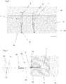
- FIG. 4 there are two insulation elements 41, 42 in a mold 50, which can also be referred to as base insulation element 41 and as outer insulation element 42.
- a concrete element 40 which, for example, as in FIG Figure 1 shown, can consist of a lower concrete layer 40a and an upper concrete layer 40b.
- the two concrete anchors 1, which are also in Figure 4 are shown, have different screwing depths into the insulation elements 41, 42. It should be noted that the condition of the left concrete anchor 1 does not actually exist during the manufacturing process according to the invention. The concrete anchor assumes this state if no concrete has been cast as part of the fastening arrangement. Only after the condition of the concrete anchor 1 shown on the right is reached, concrete is poured into the mold 50.
- the entire arrangement can be removed from the mold 50. Due to the elastic properties of the concrete anchor 1, it is now aligned along its longitudinal axis again, at least almost. Consequently, the tip 9 of the concrete anchor 1 protrudes from the outer insulation element 42.
- the tip 9 is as in Figure 5 shown, visible from the outside. It is now possible for the worker to complete the entire fastening arrangement by means of a fastening element 20 and a plate element 30, so that the in Figure 1 shown state is reached. For this purpose, the fastening element 20 is passed through the plate element 30, which has an axial extension 60, and then inserted into a hollow section 7 of the concrete anchor 1.
- the hollow section 7 can have such a diameter near the tip of the concrete anchor, so that the fastening element 20 can first be inserted into the concrete anchor 1 without a screwing movement.
- the hollow section 7 continues beyond the anchoring section 8.
- it is necessary to screw in the fastening element 20 be it in a prepared internal thread of the concrete anchor 1 or by cutting a thread into the concrete anchor by means of the fastening element 20. Since the axial extension 60 of the plate element 30 already contacts the tip 9 of the concrete anchor 1 in this state, this is driven into the insulation element 42. Consequently, the concrete anchor 1 deflects in the radial direction with the expansion element 62 spreading on the anchoring section 8.
- both the expansion element 62 and the adjoining plate element 30 offer support for the entire fastening arrangement.
- the concrete anchor with inserted fastening element 20 is shown again.
- the plate element was omitted here, because in principle the spreading function can also be implemented without a plate element.
- FIG. 1 the in Figure 1 fastening arrangement shown provided.
- This comprises a base insulation element 41, an outer insulation element 42, a concrete element 40, consisting of a lower concrete layer 40a, that is to say a concrete layer which bears on the base insulation element 41, and an upper concrete layer 40b which follows the lower concrete layer 40a.
- a concrete anchor 1 is also provided, which has a head 2.
- This head 2 has a force attack 3, which is realized, for example, by a hexagon socket or a Torx attack.
- the concrete anchor 1 has a shaft 5 with a longitudinal stop 4.
- a part of the shaft 5 is equipped with a thread 6 which, for example, can have at least twice the outer diameter as the shaft 5 itself.
- the concrete anchor 1 also has a hollow section 7, which extends from its tip 9 to at least beyond the anchoring section 8.
- a fastening element 20 is screwed into this hollow section 7, which exerts an axial force on the concrete anchor 1 due to the tensile force of a thread 21 of the fastening element 20, so that the anchoring section 8 functions as an expansion element 62.
- the axial force is realized by mutual abutment of a shaft stop 34 on the concrete anchor 1 and an axial extension 60 on the plate element 30.
- the plate element 30 comprises a plate plate 31, a plate shaft 32 and at least one plate bore 33.
Landscapes
- Engineering & Computer Science (AREA)
- General Engineering & Computer Science (AREA)
- Mechanical Engineering (AREA)
- Joining Of Building Structures In Genera (AREA)
Claims (7)
- Procédé de fabrication d'un système de fixation composé d'un ou de plusieurs éléments en béton (40), d'un ou de plusieurs éléments d'isolation (41, 42) et au moins d'un système d'ancrage pour béton, lequel comprend à son tour une tige d'ancrage pour béton (1) et un élément de fixation (20), sachant que la tige d'ancrage pour béton (1) comporte à son tour une tête (2) avec application de force (3) et une queue (5), qui définit un axe longitudinal et se termine dans une pointe (9), sachant que la queue (5) comporte une butée longitudinale (4), au moins une section filetée extérieure (6, 10) et au moins une section d'ancrage (8) avec un élément d'expansion (62) et sachant que la queue (5) peut être au moins en partie élastiquement déformée et la longueur de la tige d'ancrage pour béton (1) est plus grande entre la butée longitudinale (4) et la pointe (9) que l'épaisseur d'un ou de plusieurs éléments d'isolation (41, 42),
avec les étapes de procédé suivantes :- préparation d'un moule (50),- insertion d'un ou de plusieurs éléments d'isolation (41, 42) dans le moule,- vissage d'au moins une tige d'ancrage pour béton (1) dans un ou plusieurs éléments d'isolation (41, 42) jusqu'à ce que la butée longitudinale (4) entre en contact avec un élément d'isolation (41), sachant que la tige d'ancrage pour béton (1) subisse une déformation élastique et plie après butée de la pointe (9) sur le moule (50),- coulée d'un ou de plusieurs éléments en béton (40) sur une ou plusieurs couches d'isolation (41, 42), sachant que la tête (2) est ancrée dans un ou plusieurs éléments en béton (40) et sachant que la section d'ancrage (8) se situe dans un ou plusieurs éléments d'isolation (41, 42),- enlèvement du système d'un ou de plusieurs éléments d'isolation (41, 42), d'un ou de plusieurs éléments en béton (40) et d'au moins une tige d'ancrage pour béton (1) du moule, sachant que la déformation élastique est supprimée au moins en partie et- vissage de l'élément de fixation (20) sur la pointe (9) de la tige d'ancrage pour béton (1) dans la section creuse (7) de la queue (5) dans la tige d'ancrage pour béton (1) de telle manière que la tige d'ancrage pour béton (1) est refoulée et l'élément d'expansion (62) est expansé dans un ou plusieurs éléments d'isolation (41, 42). - Procédé selon la revendication 1, caractérisé en ce que le vissage de l'élément de fixation (20) a lieu avec la participation d'un élément en plaque (30) et l'élément de fixation (20) entraîne l'élément en plaque (30) contre la pointe (9) de la tige d'ancrage pour béton (1) .
- Procédé selon la revendication 1-2, caractérisé en ce que la butée longitudinale (4) de la tige d'ancrage pour béton (1) est une plaque s'étendant radialement.
- Procédé selon l'une quelconque des revendications précédentes, caractérisé en ce que la queue (5) de la tige d'ancrage pour béton (1) comporte deux sections filetées extérieures (6, 10).
- Procédé selon l'une quelconque des revendications précédentes, caractérisé en ce qu'une section filetée extérieure (10) est disposée sur la pointe (9).
- Procédé selon l'une quelconque des revendications précédentes, caractérisé en ce que la queue (5) de la tige d'ancrage pour béton (1) comporte une section creuse (7) partant de la pointe (9) et allant au moins au-delà de la section d'ancrage (8).
- Procédé selon la revendication 6, caractérisé en ce que la section creuse (7) de la tige d'ancrage pour béton (1) comporte au moins en partie un filetage intérieur.
Priority Applications (1)
| Application Number | Priority Date | Filing Date | Title |
|---|---|---|---|
| PL16199930T PL3173632T3 (pl) | 2015-11-30 | 2016-11-22 | Kotwa betonowa, system kotwy betonowej, układ zamocowania i sposób wytwarzania układu zamocowania |
Applications Claiming Priority (1)
| Application Number | Priority Date | Filing Date | Title |
|---|---|---|---|
| DE102015120789.3A DE102015120789A1 (de) | 2015-11-30 | 2015-11-30 | Betonanker, Betonankersystem, Befestigungsanordnung und Verfahren zum Herstellen einer Befestigungsanordnung |
Publications (2)
| Publication Number | Publication Date |
|---|---|
| EP3173632A1 EP3173632A1 (fr) | 2017-05-31 |
| EP3173632B1 true EP3173632B1 (fr) | 2020-07-22 |
Family
ID=57391822
Family Applications (1)
| Application Number | Title | Priority Date | Filing Date |
|---|---|---|---|
| EP16199930.5A Active EP3173632B1 (fr) | 2015-11-30 | 2016-11-22 | Ancrage pour béton, système d'ancrage pour béton, système de fixation et procédé de fabrication d'un système de fixation |
Country Status (4)
| Country | Link |
|---|---|
| EP (1) | EP3173632B1 (fr) |
| DE (1) | DE102015120789A1 (fr) |
| LT (1) | LT3173632T (fr) |
| PL (1) | PL3173632T3 (fr) |
Families Citing this family (2)
| Publication number | Priority date | Publication date | Assignee | Title |
|---|---|---|---|---|
| DE102018125782A1 (de) * | 2018-10-17 | 2020-04-23 | Geobrugg Ag | Befestigungs- und/oder Verbindungsvorrichtung, Verwendung der Befestigungs- und/oder Verbindungsvorrichtung, Herstellungsvorrichtung zu einer Herstellung der Befestigungs- und/oder Verbindungsvorrichtung, Verfahren zu einer Herstellung der Befestigungs- und/oder Verbindungsvorrichtung, sowie Gesteinsanker und Verfahren zu einer Montage des Gesteinsankers |
| CN109914607A (zh) * | 2019-03-05 | 2019-06-21 | 上海鹄鸫重工机械有限公司 | 一种建筑构件用自攻钉 |
Family Cites Families (12)
| Publication number | Priority date | Publication date | Assignee | Title |
|---|---|---|---|---|
| FR470525A (fr) * | 1914-04-04 | 1914-09-15 | Raoul Diaz Wagner | Boulon-écrou expansible pour la fixation des tirefonds et vis à bois ou à métaux dans du bois ou autres matériaux offrant peu de résistance aux filets des vis |
| JP2809584B2 (ja) * | 1993-12-13 | 1998-10-08 | 光洋器材株式会社 | デッキプレート用インサート |
| DE10061707A1 (de) * | 2000-12-12 | 2002-06-20 | Jens Werner | Verbindungs-, Spann- und Befestigungselement |
| WO2004053341A2 (fr) * | 2002-12-11 | 2004-06-24 | Cobra Fixations Cie Ltée - Cobra Anchors Co. Ltd | Ancrage pour murs creux |
| DE102004020852B4 (de) * | 2004-04-28 | 2006-07-13 | Hilti Ag | Eingussdübel |
| DE202008002183U1 (de) * | 2008-02-16 | 2009-06-25 | Reuter, Werner | Spreizdübel |
| CH699860A2 (de) * | 2008-11-03 | 2010-05-14 | Fischerwerke Gmbh & Co Kg | Dämmstoffbefestiger. |
| DE102009006769A1 (de) * | 2009-01-30 | 2010-08-05 | Fischerwerke Gmbh & Co. Kg | Dämmstoffhalter |
| PL217568B1 (pl) * | 2009-10-02 | 2014-07-31 | Klimas Wkręt Met Spółka Z Ograniczoną Odpowiedzialnością | Łącznik izolacji |
| DE202009015787U1 (de) * | 2009-11-18 | 2010-03-04 | Harald Zahn Gmbh | Montagevorrichtung für Solaranlagen auf Flachdächern |
| DE102010061283A1 (de) * | 2010-12-16 | 2012-06-21 | Fischerwerke Gmbh & Co. Kg | Dämmstoffhalter |
| DE102011054895A1 (de) * | 2011-10-28 | 2013-05-02 | Fischerwerke Gmbh & Co. Kg | Dämmstoffhalter zum Justieren und Befestigen von Wärmedämmplatten |
-
2015
- 2015-11-30 DE DE102015120789.3A patent/DE102015120789A1/de not_active Withdrawn
-
2016
- 2016-11-22 PL PL16199930T patent/PL3173632T3/pl unknown
- 2016-11-22 EP EP16199930.5A patent/EP3173632B1/fr active Active
- 2016-11-22 LT LTEP16199930.5T patent/LT3173632T/lt unknown
Non-Patent Citations (1)
| Title |
|---|
| None * |
Also Published As
| Publication number | Publication date |
|---|---|
| DE102015120789A1 (de) | 2017-06-01 |
| EP3173632A1 (fr) | 2017-05-31 |
| PL3173632T3 (pl) | 2020-11-16 |
| LT3173632T (lt) | 2020-09-10 |
Similar Documents
| Publication | Publication Date | Title |
|---|---|---|
| DE69803766T2 (de) | Bausystem mit individuellen bauelementen | |
| EP3559484B1 (fr) | Système d'assemblage ou de blindage de composants | |
| EP2049745B1 (fr) | Système de fixation constitué de chevilles et de clous en plastique, et procédé de montage de panneaux isolants | |
| DE10041299B4 (de) | Befestigungssystem | |
| DE3111361A1 (de) | Spreizankerschraubvorrichtung | |
| EP2481938A2 (fr) | Vis à béton et procédé d'ancrage d'une vis à béton dans un sous-sol | |
| EP2992226B1 (fr) | Système d'ancrage | |
| EP3318685B1 (fr) | Goujon d'alignement | |
| EP2044270B1 (fr) | Système de fixation et procédé de montage de plaques de matériau d'isolation | |
| DE102011102510A1 (de) | System zum Befestigen einer Dämmfassade und dafür vorgesehener Befestiger | |
| DE202009004831U1 (de) | Bauwerkanker sowie Bauwerkankersystem | |
| EP3173632B1 (fr) | Ancrage pour béton, système d'ancrage pour béton, système de fixation et procédé de fabrication d'un système de fixation | |
| EP2354567A1 (fr) | Vis de tige d'encrage | |
| WO2013120746A1 (fr) | Ancre de fixation et système de fixation comprenant une ancre de fixation | |
| EP3199824B1 (fr) | Système de fixation et son utilisation | |
| DE202010012930U1 (de) | Bauwerkanker | |
| DE102006024440B4 (de) | Schraubanker | |
| WO2012152237A1 (fr) | Vis d'ancrage composite | |
| EP3214321A1 (fr) | Cheville pour panneau de construction léger, système comprenant un panneau de construction léger et une cheville et procédé d'insertion d'une cheville dans un panneau de construction léger | |
| EP1591602B1 (fr) | Système pour fixer des éléments de construction sur un mur | |
| DE202019100898U1 (de) | Wanddübel für ein Betonfertigteil | |
| EP2740851A1 (fr) | Élément écarteur avec vitre de recouvrement | |
| EP3322904B1 (fr) | Procédé pour réaliser une liaison | |
| DE102014102395A1 (de) | Schraube und Spreizdübel | |
| EP3591243B1 (fr) | Élément de fixation pourvu d'élément de contrôle de montage destiné au contrôle d'ancrage |
Legal Events
| Date | Code | Title | Description |
|---|---|---|---|
| PUAI | Public reference made under article 153(3) epc to a published international application that has entered the european phase |
Free format text: ORIGINAL CODE: 0009012 |
|
| STAA | Information on the status of an ep patent application or granted ep patent |
Free format text: STATUS: THE APPLICATION HAS BEEN PUBLISHED |
|
| AK | Designated contracting states |
Kind code of ref document: A1 Designated state(s): AL AT BE BG CH CY CZ DE DK EE ES FI FR GB GR HR HU IE IS IT LI LT LU LV MC MK MT NL NO PL PT RO RS SE SI SK SM TR |
|
| AX | Request for extension of the european patent |
Extension state: BA ME |
|
| STAA | Information on the status of an ep patent application or granted ep patent |
Free format text: STATUS: REQUEST FOR EXAMINATION WAS MADE |
|
| 17P | Request for examination filed |
Effective date: 20171121 |
|
| RBV | Designated contracting states (corrected) |
Designated state(s): AL AT BE BG CH CY CZ DE DK EE ES FI FR GB GR HR HU IE IS IT LI LT LU LV MC MK MT NL NO PL PT RO RS SE SI SK SM TR |
|
| STAA | Information on the status of an ep patent application or granted ep patent |
Free format text: STATUS: EXAMINATION IS IN PROGRESS |
|
| 17Q | First examination report despatched |
Effective date: 20180719 |
|
| RAP1 | Party data changed (applicant data changed or rights of an application transferred) |
Owner name: SFS INTEC HOLDING AG |
|
| GRAP | Despatch of communication of intention to grant a patent |
Free format text: ORIGINAL CODE: EPIDOSNIGR1 |
|
| STAA | Information on the status of an ep patent application or granted ep patent |
Free format text: STATUS: GRANT OF PATENT IS INTENDED |
|
| INTG | Intention to grant announced |
Effective date: 20200311 |
|
| GRAS | Grant fee paid |
Free format text: ORIGINAL CODE: EPIDOSNIGR3 |
|
| GRAA | (expected) grant |
Free format text: ORIGINAL CODE: 0009210 |
|
| STAA | Information on the status of an ep patent application or granted ep patent |
Free format text: STATUS: THE PATENT HAS BEEN GRANTED |
|
| AK | Designated contracting states |
Kind code of ref document: B1 Designated state(s): AL AT BE BG CH CY CZ DE DK EE ES FI FR GB GR HR HU IE IS IT LI LT LU LV MC MK MT NL NO PL PT RO RS SE SI SK SM TR |
|
| REG | Reference to a national code |
Ref country code: GB Ref legal event code: FG4D Free format text: NOT ENGLISH |
|
| REG | Reference to a national code |
Ref country code: CH Ref legal event code: EP |
|
| REG | Reference to a national code |
Ref country code: DE Ref legal event code: R096 Ref document number: 502016010569 Country of ref document: DE |
|
| REG | Reference to a national code |
Ref country code: AT Ref legal event code: REF Ref document number: 1293657 Country of ref document: AT Kind code of ref document: T Effective date: 20200815 |
|
| REG | Reference to a national code |
Ref country code: IE Ref legal event code: FG4D Free format text: LANGUAGE OF EP DOCUMENT: GERMAN |
|
| REG | Reference to a national code |
Ref country code: FI Ref legal event code: FGE |
|
| REG | Reference to a national code |
Ref country code: DK Ref legal event code: T3 Effective date: 20201002 |
|
| REG | Reference to a national code |
Ref country code: EE Ref legal event code: FG4A Ref document number: E019644 Country of ref document: EE Effective date: 20200831 |
|
| REG | Reference to a national code |
Ref country code: NL Ref legal event code: FP |
|
| REG | Reference to a national code |
Ref country code: SE Ref legal event code: TRGR |
|
| REG | Reference to a national code |
Ref country code: NO Ref legal event code: T2 Effective date: 20200722 |
|
| PG25 | Lapsed in a contracting state [announced via postgrant information from national office to epo] |
Ref country code: BG Free format text: LAPSE BECAUSE OF FAILURE TO SUBMIT A TRANSLATION OF THE DESCRIPTION OR TO PAY THE FEE WITHIN THE PRESCRIBED TIME-LIMIT Effective date: 20201022 Ref country code: GR Free format text: LAPSE BECAUSE OF FAILURE TO SUBMIT A TRANSLATION OF THE DESCRIPTION OR TO PAY THE FEE WITHIN THE PRESCRIBED TIME-LIMIT Effective date: 20201023 Ref country code: HR Free format text: LAPSE BECAUSE OF FAILURE TO SUBMIT A TRANSLATION OF THE DESCRIPTION OR TO PAY THE FEE WITHIN THE PRESCRIBED TIME-LIMIT Effective date: 20200722 Ref country code: ES Free format text: LAPSE BECAUSE OF FAILURE TO SUBMIT A TRANSLATION OF THE DESCRIPTION OR TO PAY THE FEE WITHIN THE PRESCRIBED TIME-LIMIT Effective date: 20200722 Ref country code: PT Free format text: LAPSE BECAUSE OF FAILURE TO SUBMIT A TRANSLATION OF THE DESCRIPTION OR TO PAY THE FEE WITHIN THE PRESCRIBED TIME-LIMIT Effective date: 20201123 |
|
| PG25 | Lapsed in a contracting state [announced via postgrant information from national office to epo] |
Ref country code: RS Free format text: LAPSE BECAUSE OF FAILURE TO SUBMIT A TRANSLATION OF THE DESCRIPTION OR TO PAY THE FEE WITHIN THE PRESCRIBED TIME-LIMIT Effective date: 20200722 Ref country code: IS Free format text: LAPSE BECAUSE OF FAILURE TO SUBMIT A TRANSLATION OF THE DESCRIPTION OR TO PAY THE FEE WITHIN THE PRESCRIBED TIME-LIMIT Effective date: 20201122 |
|
| REG | Reference to a national code |
Ref country code: DE Ref legal event code: R097 Ref document number: 502016010569 Country of ref document: DE |
|
| PG25 | Lapsed in a contracting state [announced via postgrant information from national office to epo] |
Ref country code: SM Free format text: LAPSE BECAUSE OF FAILURE TO SUBMIT A TRANSLATION OF THE DESCRIPTION OR TO PAY THE FEE WITHIN THE PRESCRIBED TIME-LIMIT Effective date: 20200722 Ref country code: RO Free format text: LAPSE BECAUSE OF FAILURE TO SUBMIT A TRANSLATION OF THE DESCRIPTION OR TO PAY THE FEE WITHIN THE PRESCRIBED TIME-LIMIT Effective date: 20200722 Ref country code: CZ Free format text: LAPSE BECAUSE OF FAILURE TO SUBMIT A TRANSLATION OF THE DESCRIPTION OR TO PAY THE FEE WITHIN THE PRESCRIBED TIME-LIMIT Effective date: 20200722 |
|
| PLBE | No opposition filed within time limit |
Free format text: ORIGINAL CODE: 0009261 |
|
| STAA | Information on the status of an ep patent application or granted ep patent |
Free format text: STATUS: NO OPPOSITION FILED WITHIN TIME LIMIT |
|
| PG25 | Lapsed in a contracting state [announced via postgrant information from national office to epo] |
Ref country code: AL Free format text: LAPSE BECAUSE OF FAILURE TO SUBMIT A TRANSLATION OF THE DESCRIPTION OR TO PAY THE FEE WITHIN THE PRESCRIBED TIME-LIMIT Effective date: 20200722 |
|
| 26N | No opposition filed |
Effective date: 20210423 |
|
| PG25 | Lapsed in a contracting state [announced via postgrant information from national office to epo] |
Ref country code: MC Free format text: LAPSE BECAUSE OF FAILURE TO SUBMIT A TRANSLATION OF THE DESCRIPTION OR TO PAY THE FEE WITHIN THE PRESCRIBED TIME-LIMIT Effective date: 20200722 Ref country code: SK Free format text: LAPSE BECAUSE OF FAILURE TO SUBMIT A TRANSLATION OF THE DESCRIPTION OR TO PAY THE FEE WITHIN THE PRESCRIBED TIME-LIMIT Effective date: 20200722 |
|
| PG25 | Lapsed in a contracting state [announced via postgrant information from national office to epo] |
Ref country code: LU Free format text: LAPSE BECAUSE OF NON-PAYMENT OF DUE FEES Effective date: 20201122 |
|
| PG25 | Lapsed in a contracting state [announced via postgrant information from national office to epo] |
Ref country code: SI Free format text: LAPSE BECAUSE OF FAILURE TO SUBMIT A TRANSLATION OF THE DESCRIPTION OR TO PAY THE FEE WITHIN THE PRESCRIBED TIME-LIMIT Effective date: 20200722 |
|
| PG25 | Lapsed in a contracting state [announced via postgrant information from national office to epo] |
Ref country code: IE Free format text: LAPSE BECAUSE OF NON-PAYMENT OF DUE FEES Effective date: 20201122 |
|
| PGFP | Annual fee paid to national office [announced via postgrant information from national office to epo] |
Ref country code: AT Payment date: 20211117 Year of fee payment: 6 Ref country code: GB Payment date: 20211123 Year of fee payment: 6 Ref country code: NL Payment date: 20211119 Year of fee payment: 6 Ref country code: FR Payment date: 20211119 Year of fee payment: 6 Ref country code: DE Payment date: 20211122 Year of fee payment: 6 |
|
| PGFP | Annual fee paid to national office [announced via postgrant information from national office to epo] |
Ref country code: IT Payment date: 20211130 Year of fee payment: 6 Ref country code: CH Payment date: 20211001 Year of fee payment: 6 Ref country code: BE Payment date: 20211119 Year of fee payment: 6 |
|
| PGFP | Annual fee paid to national office [announced via postgrant information from national office to epo] |
Ref country code: PL Payment date: 20211115 Year of fee payment: 6 |
|
| PG25 | Lapsed in a contracting state [announced via postgrant information from national office to epo] |
Ref country code: TR Free format text: LAPSE BECAUSE OF FAILURE TO SUBMIT A TRANSLATION OF THE DESCRIPTION OR TO PAY THE FEE WITHIN THE PRESCRIBED TIME-LIMIT Effective date: 20200722 Ref country code: MT Free format text: LAPSE BECAUSE OF FAILURE TO SUBMIT A TRANSLATION OF THE DESCRIPTION OR TO PAY THE FEE WITHIN THE PRESCRIBED TIME-LIMIT Effective date: 20200722 Ref country code: CY Free format text: LAPSE BECAUSE OF FAILURE TO SUBMIT A TRANSLATION OF THE DESCRIPTION OR TO PAY THE FEE WITHIN THE PRESCRIBED TIME-LIMIT Effective date: 20200722 |
|
| PG25 | Lapsed in a contracting state [announced via postgrant information from national office to epo] |
Ref country code: MK Free format text: LAPSE BECAUSE OF FAILURE TO SUBMIT A TRANSLATION OF THE DESCRIPTION OR TO PAY THE FEE WITHIN THE PRESCRIBED TIME-LIMIT Effective date: 20200722 |
|
| REG | Reference to a national code |
Ref country code: DE Ref legal event code: R119 Ref document number: 502016010569 Country of ref document: DE |
|
| REG | Reference to a national code |
Ref country code: CH Ref legal event code: PL |
|
| REG | Reference to a national code |
Ref country code: NL Ref legal event code: MM Effective date: 20221201 |
|
| REG | Reference to a national code |
Ref country code: AT Ref legal event code: MM01 Ref document number: 1293657 Country of ref document: AT Kind code of ref document: T Effective date: 20221122 |
|
| GBPC | Gb: european patent ceased through non-payment of renewal fee |
Effective date: 20221122 |
|
| REG | Reference to a national code |
Ref country code: BE Ref legal event code: MM Effective date: 20221130 |
|
| PG25 | Lapsed in a contracting state [announced via postgrant information from national office to epo] |
Ref country code: LI Free format text: LAPSE BECAUSE OF NON-PAYMENT OF DUE FEES Effective date: 20221130 Ref country code: CH Free format text: LAPSE BECAUSE OF NON-PAYMENT OF DUE FEES Effective date: 20221130 Ref country code: AT Free format text: LAPSE BECAUSE OF NON-PAYMENT OF DUE FEES Effective date: 20221122 |
|
| P01 | Opt-out of the competence of the unified patent court (upc) registered |
Effective date: 20230622 |
|
| PG25 | Lapsed in a contracting state [announced via postgrant information from national office to epo] |
Ref country code: NL Free format text: LAPSE BECAUSE OF NON-PAYMENT OF DUE FEES Effective date: 20221201 |
|
| PG25 | Lapsed in a contracting state [announced via postgrant information from national office to epo] |
Ref country code: IT Free format text: LAPSE BECAUSE OF NON-PAYMENT OF DUE FEES Effective date: 20221122 Ref country code: GB Free format text: LAPSE BECAUSE OF NON-PAYMENT OF DUE FEES Effective date: 20221122 Ref country code: DE Free format text: LAPSE BECAUSE OF NON-PAYMENT OF DUE FEES Effective date: 20230601 |
|
| PG25 | Lapsed in a contracting state [announced via postgrant information from national office to epo] |
Ref country code: FR Free format text: LAPSE BECAUSE OF NON-PAYMENT OF DUE FEES Effective date: 20221130 Ref country code: BE Free format text: LAPSE BECAUSE OF NON-PAYMENT OF DUE FEES Effective date: 20221130 |
|
| PGFP | Annual fee paid to national office [announced via postgrant information from national office to epo] |
Ref country code: NO Payment date: 20231121 Year of fee payment: 8 Ref country code: LV Payment date: 20231117 Year of fee payment: 8 Ref country code: LT Payment date: 20231109 Year of fee payment: 8 Ref country code: FI Payment date: 20231120 Year of fee payment: 8 Ref country code: EE Payment date: 20231120 Year of fee payment: 8 Ref country code: DK Payment date: 20231122 Year of fee payment: 8 |
|
| PG25 | Lapsed in a contracting state [announced via postgrant information from national office to epo] |
Ref country code: PL Free format text: LAPSE BECAUSE OF NON-PAYMENT OF DUE FEES Effective date: 20221122 |
|
| REG | Reference to a national code |
Ref country code: LT Ref legal event code: MM4D Effective date: 20241122 |
|
| REG | Reference to a national code |
Ref country code: EE Ref legal event code: MM4A Ref document number: E019644 Country of ref document: EE Effective date: 20241130 |
|
| REG | Reference to a national code |
Ref country code: DK Ref legal event code: EBP Effective date: 20241130 |
|
| PG25 | Lapsed in a contracting state [announced via postgrant information from national office to epo] |
Ref country code: FI Free format text: LAPSE BECAUSE OF NON-PAYMENT OF DUE FEES Effective date: 20241122 |
|
| PG25 | Lapsed in a contracting state [announced via postgrant information from national office to epo] |
Ref country code: LT Free format text: LAPSE BECAUSE OF NON-PAYMENT OF DUE FEES Effective date: 20241122 |
|
| PG25 | Lapsed in a contracting state [announced via postgrant information from national office to epo] |
Ref country code: NO Free format text: LAPSE BECAUSE OF NON-PAYMENT OF DUE FEES Effective date: 20241130 |
|
| PG25 | Lapsed in a contracting state [announced via postgrant information from national office to epo] |
Ref country code: LV Free format text: LAPSE BECAUSE OF NON-PAYMENT OF DUE FEES Effective date: 20241122 |
|
| PG25 | Lapsed in a contracting state [announced via postgrant information from national office to epo] |
Ref country code: EE Free format text: LAPSE BECAUSE OF NON-PAYMENT OF DUE FEES Effective date: 20241130 |
|
| PG25 | Lapsed in a contracting state [announced via postgrant information from national office to epo] |
Ref country code: DK Free format text: LAPSE BECAUSE OF NON-PAYMENT OF DUE FEES Effective date: 20241130 |
|
| PGFP | Annual fee paid to national office [announced via postgrant information from national office to epo] |
Ref country code: SE Payment date: 20251119 Year of fee payment: 10 |