EP3173656A1 - Stossdämpfungsvorrichtung - Google Patents
Stossdämpfungsvorrichtung Download PDFInfo
- Publication number
- EP3173656A1 EP3173656A1 EP14898062.6A EP14898062A EP3173656A1 EP 3173656 A1 EP3173656 A1 EP 3173656A1 EP 14898062 A EP14898062 A EP 14898062A EP 3173656 A1 EP3173656 A1 EP 3173656A1
- Authority
- EP
- European Patent Office
- Prior art keywords
- cushioning members
- shock absorbing
- absorbing device
- holding
- stress
- Prior art date
- Legal status (The legal status is an assumption and is not a legal conclusion. Google has not performed a legal analysis and makes no representation as to the accuracy of the status listed.)
- Granted
Links
Images



Classifications
-
- F—MECHANICAL ENGINEERING; LIGHTING; HEATING; WEAPONS; BLASTING
- F16—ENGINEERING ELEMENTS AND UNITS; GENERAL MEASURES FOR PRODUCING AND MAINTAINING EFFECTIVE FUNCTIONING OF MACHINES OR INSTALLATIONS; THERMAL INSULATION IN GENERAL
- F16F—SPRINGS; SHOCK-ABSORBERS; MEANS FOR DAMPING VIBRATION
- F16F1/00—Springs
- F16F1/02—Springs made of steel or other material having low internal friction; Wound, torsion, leaf, cup, ring or the like springs, the material of the spring not being relevant
- F16F1/021—Springs made of steel or other material having low internal friction; Wound, torsion, leaf, cup, ring or the like springs, the material of the spring not being relevant characterised by their composition, e.g. comprising materials providing for particular spring properties
-
- B—PERFORMING OPERATIONS; TRANSPORTING
- B64—AIRCRAFT; AVIATION; COSMONAUTICS
- B64G—COSMONAUTICS; VEHICLES OR EQUIPMENT THEREFOR
- B64G1/00—Cosmonautic vehicles
- B64G1/22—Parts of, or equipment specially adapted for fitting in or to, cosmonautic vehicles
-
- F—MECHANICAL ENGINEERING; LIGHTING; HEATING; WEAPONS; BLASTING
- F16—ENGINEERING ELEMENTS AND UNITS; GENERAL MEASURES FOR PRODUCING AND MAINTAINING EFFECTIVE FUNCTIONING OF MACHINES OR INSTALLATIONS; THERMAL INSULATION IN GENERAL
- F16F—SPRINGS; SHOCK-ABSORBERS; MEANS FOR DAMPING VIBRATION
- F16F15/00—Suppression of vibrations in systems; Means or arrangements for avoiding or reducing out-of-balance forces, e.g. due to motion
- F16F15/02—Suppression of vibrations of non-rotating, e.g. reciprocating systems; Suppression of vibrations of rotating systems by use of members not moving with the rotating systems
- F16F15/04—Suppression of vibrations of non-rotating, e.g. reciprocating systems; Suppression of vibrations of rotating systems by use of members not moving with the rotating systems using elastic means
- F16F15/06—Suppression of vibrations of non-rotating, e.g. reciprocating systems; Suppression of vibrations of rotating systems by use of members not moving with the rotating systems using elastic means with metal springs
-
- F—MECHANICAL ENGINEERING; LIGHTING; HEATING; WEAPONS; BLASTING
- F16—ENGINEERING ELEMENTS AND UNITS; GENERAL MEASURES FOR PRODUCING AND MAINTAINING EFFECTIVE FUNCTIONING OF MACHINES OR INSTALLATIONS; THERMAL INSULATION IN GENERAL
- F16F—SPRINGS; SHOCK-ABSORBERS; MEANS FOR DAMPING VIBRATION
- F16F2224/00—Materials; Material properties
- F16F2224/02—Materials; Material properties solids
- F16F2224/0208—Alloys
-
- F—MECHANICAL ENGINEERING; LIGHTING; HEATING; WEAPONS; BLASTING
- F16—ENGINEERING ELEMENTS AND UNITS; GENERAL MEASURES FOR PRODUCING AND MAINTAINING EFFECTIVE FUNCTIONING OF MACHINES OR INSTALLATIONS; THERMAL INSULATION IN GENERAL
- F16F—SPRINGS; SHOCK-ABSORBERS; MEANS FOR DAMPING VIBRATION
- F16F2224/00—Materials; Material properties
- F16F2224/02—Materials; Material properties solids
- F16F2224/0258—Shape-memory metals, e.g. Ni-Ti alloys
-
- F—MECHANICAL ENGINEERING; LIGHTING; HEATING; WEAPONS; BLASTING
- F16—ENGINEERING ELEMENTS AND UNITS; GENERAL MEASURES FOR PRODUCING AND MAINTAINING EFFECTIVE FUNCTIONING OF MACHINES OR INSTALLATIONS; THERMAL INSULATION IN GENERAL
- F16F—SPRINGS; SHOCK-ABSORBERS; MEANS FOR DAMPING VIBRATION
- F16F2228/00—Functional characteristics, e.g. variability, frequency-dependence
- F16F2228/08—Functional characteristics, e.g. variability, frequency-dependence pre-stressed
-
- F—MECHANICAL ENGINEERING; LIGHTING; HEATING; WEAPONS; BLASTING
- F16—ENGINEERING ELEMENTS AND UNITS; GENERAL MEASURES FOR PRODUCING AND MAINTAINING EFFECTIVE FUNCTIONING OF MACHINES OR INSTALLATIONS; THERMAL INSULATION IN GENERAL
- F16F—SPRINGS; SHOCK-ABSORBERS; MEANS FOR DAMPING VIBRATION
- F16F2236/00—Mode of stressing of basic spring or damper elements or devices incorporating such elements
- F16F2236/04—Compression
- F16F2236/045—Compression the spring material being generally enclosed
Definitions
- the present invention relates to a shock absorbing device.
- the present invention relates to a shock absorbing device having high strength and rigidity and excellent attenuation characteristic, a shock absorbing device enabling miniaturization and weight reduction to be realized, a shock absorbing device free from worry about degassing, and a shock absorbing device having stable damping and stiffness characteristics in wide temperature range.
- Patent Document 1 JP-A-2012-197864 discloses a hysteretic damper having shape self- restoration capability added thereto by tensile force of a super elastic alloy.
- the hysteretic damper comprises a first super elastic alloy member to which a tensile force acts under tension and a second super elastic alloy member to which a tensile force acts under compression, has a structure for carrying out self-restoration of a damper shape by the first super elastic alloy member and the second super elastic alloy member, and characteristics under tension and compression can be set freely.
- a shock absorbing device used for an aerospace field is required to be small in size and weight, and to decrease degassing procedures and so on.
- a shock absorbing device which is suitable for an aerospace field, small in size and weight, and has high strength and rigidity and excellent attenuation characteristic has not yet been necessarily provided.
- An object of the present invention is to provide a shock absorbing device having high strength and rigidity and excellent attenuation characteristic. Furthermore, another object of the present invention is to provide a shock absorbing device enabling miniaturization and weight reduction to be realized. A further object of the present invention is to provide a shock absorbing device free from worry about degassing, and also, a shock absorbing device having stable temperature characteristic.
- a shock absorbing device for connecting a first member and a second member, and applicable for shock between said first member and said second member, comprising: first cushioning members and second cushioning members, and a holding connecting mechanism for holding said first member through said first cushioning members and said second cushioning members, and being connected to said second member, wherein said first cushioning members, said second cushioning members and said first member are arranged in order of said first cushioning members, said first member and said second cushioning members, said holding connecting mechanism holds said first member by clamping said first cushioning members, said first member and said second cushioning members from outside of said first cushioning members and said second cushioning members while adding stress to said first cushioning members and said second cushioning members, and said first member and said second member are connected thereby.
- a shock absorbing device may have following features: said holding connecting mechanism comprises a first coupler located on a side of said first surface and a second coupler located on a side of said second surface, said first coupler comprises a first holding portion for holding said first cushioning members between said plate material and said first holding portion, and a first connecting portion being connected to said second coupler through said penetration hole, said second coupler comprises a second holding portion for holding said second cushioning members between said plate material and said second holding portion, and a second connecting portion being connected to said first coupler through said penetration hole, said first cushioning members are subject to said stress between a first holding portion and said plate material, and second cushioning members are subject to said stress between a second holding portion and said plate material by connecting said first connecting portion and said second connecting portion.
- said first cushioning members and said second cushioning members may comprise a plurality of columnar cushioning members, and said plurality of columnar cushioning members may be arranged around said first connecting portion and said second connecting portion.
- said first cushioning members and said second cushioning members may comprise cylindrical cushioning members having a penetration hole between a top surface and a bottom surface, and said first connecting portion and said second connecting portion may be connected through said penetration hole of said cylindrical cushioning members.
- a shock absorbing device may have following features: said holding connecting mechanism comprises a first holding portion arranged on a side of said first surface, a second holding portion arranged on a side of said second surface, and a connecting portion for connecting said first holding portion and said second holding portion through said penetration hole, said first cushioning members and said second cushioning members comprises a plurality of plate cushioning members, said plurality of plate cushioning members are deflected each other, one end is fixed on said first member, and another end is fixed on said first holding portion or said second holding portion, and stress will be applied to said plate cushioning members thereby.
- Said first cushioning members and said second cushioning members may be made of singlecrystal shape memory alloy, and said singlecrystal shape memory alloy is in austenite condition in working environment temperature, and becomes martensite condition by adding stress.
- said holding connecting mechanism may be adjusted so that the stress to be applied to said first cushioning members and said second cushioning members in a condition which said first member is held between said first cushioning members and said second cushioning members is neutrality of stress range having the condition that said singlecrystal shape memory alloy is in martensite condition.
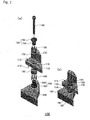
- Fig. 1 shows a shock absorbing device 100.
- Fig. 1 (a) is an exploded perspective view, and (b) is an assembly perspective view.
- Fig. 2 shows a cross-sectional view of a shock absorbing device 100.
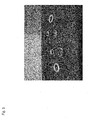
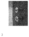
- Figs. 3 and 4 are photos showing a partially assembled state of a shock absorbing device 100, respectively, and
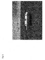
- Fig. 5 is a photo showing an assembled state of a shock absorbing device 100.
- Fig. 6 is a photo showing a state that a shock absorbing device 100 is arranged between a first member 110 and a second member 120.
- a shock absorbing device 100 connects a first member 110 and a second member 120, and suitable for cushioning the first member 110 and the second member 110.
- a second member 120 maybe satellites, for example, such as a body (housing) of an apparatus which is difficult to avoid vibration or shock to be added to the body.
- a first member 110 is fixed on a body (housing) such as a precision apparatus and so on, and also a supporting member for a built-in apparatus which should prevent propagation of vibration from the body.
- the vibration or shock to be added to the second member 120 can be suppressed by arranging a shock absorbing device 100 between the second member 120 and the first member 110.
- a shock absorbing device 100 comprises first cushioning members 130, second cushioning members 140, and a holding connecting mechanism.
- the first cushioning members 130, the second cushioning members 140 and the first member 110 are arranged in order of a first cushioning members 130, a first member 110 and a second cushioning members 140, and a holding connecting mechanism holds a first member 110 by clamping the first cushioning members 130 and the second cushioning members 140 from the outside.
- the holding connecting mechanism holds the first member 110 through the first cushioning members 130 and the second cushioning members 140.
- the holding connecting mechanism is connected to the second member 120. Accordingly, the first member 110 held by the holding connecting mechanism is also supported by the second member 120 through the holding connecting mechanism, and vibration and shock added to the second member 120 are absorbed by the first cushioning members 130 and the second cushioning members 140 and the propagation of the vibration and so on to the first member 110 can be suppressed.
- the first member 110 is a plate material comprising a first surface 112 and a second surface 114 which is an opposite surface of the first surface 112.
- the first member 110 of the plate material comprises a penetration hole 116 reaching the second surface 114 from the first surface 112.
- the holding connecting mechanism comprises a first coupler 150 located on a side of the first surface 112 and a second coupler 160 located on a side of the second surface 114.
- the first coupler 150 comprises a first holding portion 152 and a first connecting portion 154
- a second coupler 160 comprises a second holding portion 162 and a second connecting portion 164.
- the first holding portion 152 holds the first cushioning members 130 between the first member 110 of the plate material and the first holding portion 152, and the first connecting portion 154 is connected to the second coupler 160 through the penetration hole 116.
- the second holding portion 162 holds the second cushioning members 140 between the first member 110 of the plate material and the second holding portion 162, and the second connecting portion 164 is connected to the first coupler 150 through the penetration hole 116.
- the first cushioning members 130 comprise a plurality of columnar cushioning members, which are movably held the inside of a hole 172 formed in a first collar 170. Since the plurality of columnar cushioning members are held in the hole 172 of the first collar 170, the first cushioning members 130 are arranged around the first connecting portion 154. One end of the columnar first cushioning member 130 is abutted on a bottom surface of the hole 172, and another end is abutted on the first holding portion 152 of the first coupler 150. By tightening a bolt 190, the first coupler 150 is pressed in a direction of the first member 110 to be held, and the first cushioning members 130 are subject to stress.
- the second cushioning members 140 comprise a plurality of columnar cushioning members, which are movably held inside of a hole 182 formed in a second collar 180. Since the plurality of columnar cushioning members are held in the hole 182 of the second collar 180, the second cushioning members 140 are arranged around the second connecting portion 164. One end of the columnar second cushioning member 140 is abutted on a bottom surface of the hole 182, and another end is abutted on the second holding portion 162 of the second coupler 160. By tightening the bolt 190, the second coupler 160 is pressed in a direction of the first member 110 to be held, and the second cushioning members 140 are subject to stress.
- the first cushioning members 140 are subject to stress between the first holding portion 152 and the plate material, and the second cushioning members 140 are subject to stress between the second holding portion 162 and the plate material.
- the first connecting portion 154 and the second connecting portion 164 are engaged on an engaging surfaced 192, further clamping force is not applied to the first cushioning members 130 and the second cushioning members 140, and the stress applied to a first cushioning members 130 and the second cushioning members 140 is restricted.
- the shock absorbing device 100 under a state that the shock absorbing device 100 is assembled and arranged between the first member 110 and the second member 120, if it is in a state of neutrality without adding vibration and so on, a certain stress is applied to the first cushioning members 130 and the second cushioning members 140.
- a singlecrystal shape memory alloy should be noted.
- the singlecrystal shape memory alloy of copper/aluminum/nickel series is preferable.
- the singlecrystal shape memory alloy becomes austenite condition in a working environment temperature, and it is preferable to be martensite condition by applying the stress.
- Fig. 7 is a graph showing a stress-strain characteristic of the singlecrystal shape memory alloy of copper/aluminum/nickel series.
- the stress-strain characteristic in Fig. 7 shows hysteresis that the stress increases between 0 to 300MPa, and decreases to 0MPa thereafter.
- the singlecrystal shape memory alloy of copper/aluminum/nickel series are in austenite condition which increases in strain in proportion to the stress from O point to A point, and become martensite condition which large distortion will be made by a small increase of stress from A point to B point. Beyond a maximum distortion (B point) in the martensite condition, after applying the stress and decreasing the same, the martensite condition can be obtained between C point to D point. Beyond D point, it becomes austenite condition.
- a shock absorbing device 100 uses a shape memory alloy which becomes the martensite condition by applying the stress as the first cushioning members 130 and the second cushioning members 140. Namely, under a state that the shock absorbing device 100 is arranged between the first member 110 and the second member 120, and neutrality state without adding vibration and so on is kept, a certain stress is applied in advance to the first cushioning members 130 and the second cushioning members 140 so as to be martensite condition.
- the stress to be applied in advance namely the stress to be applied to the first cushioning members 130 and the second cushioning members 140 in a state that the first member 110 is held between the first cushioning members 130 and the second cushioning members 140, is neutrality of the stress range in the condition that the singlecrystal shape memory alloy is in the martensite condition. It is preferable that the stress to be applied in advance has an intermediate value of each stress at A point and D point in Fig. 7 , or an intermediate value of each stress at B point and C point.
- the value of the stress to be applied in advance can be determined by adjusting the holding connecting mechanism.
- neutrality of the stress range in the martensite condition can be obtained in a manner that lengths of the first connecting portion 154 of the first coupler 150 and the second connecting portion 164 of the second coupler 160, and lengths of the first cushioning members 130 and the second cushioning members 140 are adjusted so that distortion of the first cushioning members 130 and the second cushioning members 140 becomes 4.5%.
- the shape memory alloy is used for the first cushioning members 130 and the second cushioning members 140, and the shape memory alloy is in martensite condition by applying the stress in advance. Therefore, damping force can be obtained from a hysteresis loop in the martensite condition, and excellent attenuation characteristic can be obtained while maintaining high strength and rigidity.
- the a singlecrystal shape memory alloy especially the singlecrystal shape memory alloy of copper/aluminum/nickel series is used as the first cushioning members 130 and the second cushioning members 140, strain range becomes relatively large 9% in the martensite condition, and the stress range of the hysteresis becomes narrow.
- the singlecrystal shape memory alloy of copper/aluminum/nickel series has wide transition temperature range of -270°C to +250°C, stability of the temperature characteristic of the shock absorbing device 100 can be realized. Furthermore, the shock absorbing device 100 consist of metals, and there can be obtained the device free from worry about degassing.
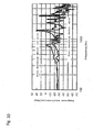
- Figs. 8 to 10 are graphs showing a result of a shock test, in which a test is carried out about vibration state of the first member 110 when the shock is added to the second member 120.
- Fig. 8 shows a time response of acceleration of the first member 110
- Fig. 9 shows frequency response of acceleration of the first member 110
- Fig. 10 shows frequency response of response acceleration of the first member 110 in a case the shock absorbing device 100 exists or not, respectively.
- an absolute value of the acceleration is small in comparison with the case the shock absorbing device 100 does not exist, and it is apparent that the acceleration and response acceleration are reduced in high frequency range more than 1 kHz.
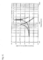
- Fig. 11 is a graph showing a result of a random vibration test, and frequency response of response magnification in a case the shock absorbing device 100 exists or not, respectively.
- a maximum value of the response magnification is largely reduced in comparison with the case the shock absorbing device 100 does not exist, and it is apparent that a peak value is shifted to a low frequency side.
- the test found that the vibration and shock are reduced by the shock absorbing device 100, in particular, vibration in a high frequency range more than 1 kHz can be reduced.
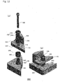
- third cushioning members 230 and fourth cushioning members 240 can be included.
- Fig. 12 (a) is an exploded perspective view, and (b) is an assembly perspective view.
- the shock absorbing device 200 is made by eliminating the first collar 170 and the second collar 180 of the shock absorbing device 100, and replacing the first cushioning members 130 and the second cushioning members 140 with the third cushioning members 230 and the fourth cushioning members 240.
- the third cushioning members 230 and the fourth cushioning members 240 are cylindrical cushioning members and comprise penetration holes 232 and 242 between a top surface to a bottom surface, respectively.
- the first connecting portion 154 and the second connecting portion 164 are connected through the penetration holes 232 and 242 of the cylindrical cushioning members.
- the shock absorbing device 200 has a similar effect as that of the shock absorbing device 100.
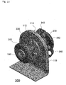
- a shock absorbing device 300 of Fig. 13 fifth cushioning members 330 and sixth cushioning members 240 can be included.
- Fig. 13 shows a perspective view of the shock absorbing device 300.
- the first member 110 is the plate material comprising the first surface 112 and the second surface 114 which is an opposite surface of the first surface 112, and the first member 110 of the plate material comprises the penetration hole 116 reaching the second surface 114 from the first surface 112.
- the holding connecting mechanism comprises a third holding portion 352 arranged on a side of the first surface 112, a fourth holding portion 362 arranged on a side of the second surface 114, and a connecting portion 370 for connecting the third holding portion 352 and the fourth holding portion 362 through the penetration hole 116.
- the fifth cushioning members 330 and the sixth cushioning members 340 comprise a plurality of plate cushioning members, which are deflected each other, one end is fixed on the first member 110, and another end is fixed on the third holding portion 352 or the fourth holding portion 362. The stress will be applied to the plate cushioning members thereby.
- the fifth cushioning members 330 and the sixth cushioning members 340 of the shock absorbing device 300 have a plate shape, which is transitional to the martensite condition by bending stress. This is a different point from that the first cushioning members 130 and the second cushioning members 140 of the shock absorbing device 100, or the third cushioning members 230 and the fourth cushioning members 240 of the shock absorbing device 200 are transitional to the martensite condition by compressed force. Since the fifth cushioning members 330 and the sixth cushioning members 340 have a plate shape, the shock absorbing device 300 is excellent in absorbing shock at low frequency range in comparison with the shock absorbing device 100 or the shock absorbing device 200. Other than this point, similar effect as that of the shock absorbing device 100 or the shock absorbing device 200 can be obtained.
Landscapes
- Engineering & Computer Science (AREA)
- General Engineering & Computer Science (AREA)
- Mechanical Engineering (AREA)
- Aviation & Aerospace Engineering (AREA)
- Remote Sensing (AREA)
- Physics & Mathematics (AREA)
- Acoustics & Sound (AREA)
- Vibration Dampers (AREA)
- Vibration Prevention Devices (AREA)
Applications Claiming Priority (1)
| Application Number | Priority Date | Filing Date | Title |
|---|---|---|---|
| PCT/JP2014/069286 WO2016013054A1 (ja) | 2014-07-22 | 2014-07-22 | 緩衝装置 |
Publications (3)
| Publication Number | Publication Date |
|---|---|
| EP3173656A1 true EP3173656A1 (de) | 2017-05-31 |
| EP3173656A4 EP3173656A4 (de) | 2018-04-18 |
| EP3173656B1 EP3173656B1 (de) | 2019-09-25 |
Family
ID=55162612
Family Applications (1)
| Application Number | Title | Priority Date | Filing Date |
|---|---|---|---|
| EP14898062.6A Active EP3173656B1 (de) | 2014-07-22 | 2014-07-22 | Stossdämpfungsvorrichtung |
Country Status (5)
| Country | Link |
|---|---|
| US (1) | US10119587B2 (de) |
| EP (1) | EP3173656B1 (de) |
| JP (1) | JP6392845B2 (de) |
| ES (1) | ES2763100T3 (de) |
| WO (1) | WO2016013054A1 (de) |
Families Citing this family (3)
| Publication number | Priority date | Publication date | Assignee | Title |
|---|---|---|---|---|
| US10655697B2 (en) * | 2016-11-23 | 2020-05-19 | Itt Manufacturing Enterprises Llc | Vibration isolator |
| EP3872436A4 (de) * | 2018-10-23 | 2022-07-27 | Wel Research Co., Ltd. | Antriebsvorrichtung |
| US12594822B2 (en) * | 2023-02-03 | 2026-04-07 | GM Global Technology Operations LLC | Super elastic shape memory alloys based solid-state vibration isolation elements for electric drivetrains |
Family Cites Families (38)
| Publication number | Priority date | Publication date | Assignee | Title |
|---|---|---|---|---|
| US4401290A (en) * | 1981-03-23 | 1983-08-30 | 4-S Oil Company, Inc. | Stabilized seat |
| US4713714A (en) * | 1985-11-26 | 1987-12-15 | Motorola Computer Systems, Inc. | Computer peripheral shock mount for limiting motion-induced errors |
| JP3525567B2 (ja) * | 1995-07-17 | 2004-05-10 | 東海ゴム工業株式会社 | 筒形防振支持体 |
| JPH0989045A (ja) * | 1995-09-27 | 1997-03-31 | Nec Eng Ltd | 緩衝支持構造 |
| US5641153A (en) * | 1995-12-06 | 1997-06-24 | Lord Corporation | Auxiliary damper for rubber suspension mountings |
| US5842677A (en) * | 1996-09-26 | 1998-12-01 | Lord Corporation | Safetied sandwich mount assembly with integral holding and centering feature |
| US5799930A (en) * | 1997-01-30 | 1998-09-01 | Means Industries, Inc. | Body mount assembly |
| DE29710578U1 (de) * | 1997-06-17 | 1997-08-28 | Woco Franz-Josef Wolf & Co, 63628 Bad Soden-Salmünster | Einknüpflager |
| US6523817B1 (en) * | 1999-04-23 | 2003-02-25 | The Goodyear Tire & Rubber Company | Interlocking vehicle body mount |
| US6820908B1 (en) * | 2000-04-28 | 2004-11-23 | Freundenberg-Nok General Partnership | Isolation mount |
| US6502883B2 (en) * | 2000-12-04 | 2003-01-07 | Cooper Technology Services, Llc | Two stage body mount rebound cushion |
| TW551768U (en) * | 2002-01-18 | 2003-09-01 | Coretronic Corp | Multi-axis adjustment device |
| FR2852371B1 (fr) * | 2003-03-12 | 2006-12-01 | Isolateur de vibrations et/ou de chocs | |
| EP1618316B1 (de) * | 2003-04-30 | 2010-10-27 | Trelleborg Ab | System zur schwingungsdämpfung |
| JP2004334959A (ja) * | 2003-05-06 | 2004-11-25 | Sharp Corp | 記憶装置の緩衝装置 |
| KR100514891B1 (ko) * | 2003-11-07 | 2005-09-14 | 현대자동차주식회사 | 차량용 롤로드 |
| DE102004019242A1 (de) * | 2004-04-16 | 2005-11-17 | Fraunhofer-Gesellschaft zur Förderung der angewandten Forschung e.V. | Schnittstelle mit Schubableitung zum Dämpfen mechanischer Schwingungen |
| US7503552B2 (en) * | 2004-06-18 | 2009-03-17 | Basf Corporation | Mount assembly |
| TWI260482B (en) * | 2005-02-23 | 2006-08-21 | Asustek Comp Inc | Shockproof locking assembly device |
| US7261365B2 (en) * | 2005-03-09 | 2007-08-28 | Basf Corporation | Vehicle body mount assembly |
| US7163200B2 (en) * | 2005-03-09 | 2007-01-16 | Basf Corporation | Interlocking mount assembly for a vehicle |
| US7416174B2 (en) * | 2005-05-12 | 2008-08-26 | Cooper Standard Automotive | Mount assembly |
| EP1770302A1 (de) * | 2005-09-30 | 2007-04-04 | Acandis GmbH & Co. KG | Dämpfungsverfahren und Dämpfungseinrichtung |
| US7682117B2 (en) * | 2006-09-27 | 2010-03-23 | Illinois Tool Works Inc. | Work piece isolating assembly |
| WO2009070664A1 (en) * | 2007-11-27 | 2009-06-04 | Lord Corporation | Center-bonded isolation mounting assembly |
| DE102007061116A1 (de) * | 2007-12-19 | 2009-06-25 | Robert Bosch Gmbh | Steuergerätegehäuse |
| JP5355901B2 (ja) * | 2008-02-21 | 2013-11-27 | 日立建機株式会社 | 防振支持装置 |
| FR2935769B1 (fr) * | 2008-09-10 | 2016-08-12 | Renault Sas | Articulation elastique de suspension de vehicule automobile et structure de vehicule automobile comportant une telle articulation |
| JP5196587B2 (ja) * | 2009-10-29 | 2013-05-15 | Necエンジニアリング株式会社 | プリント配線基板用緩衝装置 |
| EP2532918B1 (de) * | 2010-02-04 | 2018-06-27 | Bridgestone Corporation | Schwingungsdämpfungsvorrichtung |
| WO2011156667A1 (en) * | 2010-06-10 | 2011-12-15 | Grand Rapids Controls Co., Llc | Lift strut with mechanical spring element |
| US8646760B2 (en) * | 2010-06-22 | 2014-02-11 | Honeywell International Inc. | Chassis mounting system |
| JP5290260B2 (ja) * | 2010-10-29 | 2013-09-18 | 東海ゴム工業株式会社 | タンク用ゴムクッション |
| JP5784912B2 (ja) * | 2011-01-06 | 2015-09-24 | 東洋ゴム工業株式会社 | 防振装置 |
| JP5762780B2 (ja) | 2011-03-22 | 2015-08-12 | 日本車輌製造株式会社 | 履歴型ダンパー |
| FR3013684B1 (fr) * | 2013-11-22 | 2017-10-13 | Astrium Sas | Structure porteuse de satellite comportant un dispositif de liaison amortissante |
| DE102014216670B4 (de) * | 2014-08-21 | 2016-05-19 | Ford Global Technologies, Llc | Lagerbuchse |
| US10655697B2 (en) * | 2016-11-23 | 2020-05-19 | Itt Manufacturing Enterprises Llc | Vibration isolator |
-
2014
- 2014-07-22 WO PCT/JP2014/069286 patent/WO2016013054A1/ja not_active Ceased
- 2014-07-22 EP EP14898062.6A patent/EP3173656B1/de active Active
- 2014-07-22 JP JP2016503034A patent/JP6392845B2/ja not_active Expired - Fee Related
- 2014-07-22 ES ES14898062T patent/ES2763100T3/es active Active
-
2017
- 2017-01-23 US US15/413,148 patent/US10119587B2/en active Active
Also Published As
| Publication number | Publication date |
|---|---|
| US10119587B2 (en) | 2018-11-06 |
| ES2763100T3 (es) | 2020-05-27 |
| US20170152906A1 (en) | 2017-06-01 |
| EP3173656B1 (de) | 2019-09-25 |
| WO2016013054A1 (ja) | 2016-01-28 |
| JPWO2016013054A1 (ja) | 2017-06-22 |
| JP6392845B2 (ja) | 2018-09-19 |
| EP3173656A4 (de) | 2018-04-18 |
Similar Documents
| Publication | Publication Date | Title |
|---|---|---|
| JP5831734B2 (ja) | 慣性質量ダンパー | |
| Zhou et al. | An efficient vibration energy harvester with a multi-mode dynamic magnifier | |
| Kalathur et al. | Column dampers with negative stiffness: high damping at small amplitude | |
| US10181781B2 (en) | Enhanced magnetic vibration damper with mechanical impedance matching | |
| US8672107B2 (en) | Compact vibration damper | |
| US10119587B2 (en) | Shock absorbing device | |
| US11131360B2 (en) | Vibration isolation apparatuses for crystal oscillators | |
| CN106838111B (zh) | 阻尼隔振系统及复合阻尼隔振器 | |
| US11624420B1 (en) | Isolation system and method | |
| CN103363010B (zh) | 屈曲板型准零刚度隔振器 | |
| Choi et al. | Smart damper using the combination of magnetic friction and pre-compressed rubber springs | |
| KR20110081389A (ko) | 안테나장치 | |
| CN108240415B (zh) | 复合屈曲梁/板负刚度动力吸振器的大载荷高阻尼减振器 | |
| US20140021665A1 (en) | Vibration and shock isolator | |
| EP3312097B1 (de) | Passives leichtes dämpfungsglied für raumfahrzeug | |
| CN104455195A (zh) | 全金属多向隔振器 | |
| CN108317201A (zh) | 一种多稳态冲击隔离装置 | |
| US20200191232A1 (en) | Coaxial Spring Damper Device and System | |
| JP2017053128A (ja) | 減衰装置の取付構造 | |
| JP6729222B2 (ja) | エネルギ吸収デバイス及び免震構造 | |
| CN104677579B (zh) | 一种用于液氢导管位移加载振动的弹簧平衡系统 | |
| JP2017180658A (ja) | 防振装置 | |
| CN111043213A (zh) | 稳态可控层合压杆及基于该层合压杆的瞬态振动抑制结构 | |
| JP2009002359A (ja) | エネルギー吸収装置 | |
| Toluwaloju et al. | Exploiting Weak Softening in Linear Spring for Improved Near Resonant Vibration Isolation in Pivoted Levered Mechanisms |
Legal Events
| Date | Code | Title | Description |
|---|---|---|---|
| STAA | Information on the status of an ep patent application or granted ep patent |
Free format text: STATUS: THE INTERNATIONAL PUBLICATION HAS BEEN MADE |
|
| PUAI | Public reference made under article 153(3) epc to a published international application that has entered the european phase |
Free format text: ORIGINAL CODE: 0009012 |
|
| STAA | Information on the status of an ep patent application or granted ep patent |
Free format text: STATUS: REQUEST FOR EXAMINATION WAS MADE |
|
| 17P | Request for examination filed |
Effective date: 20170221 |
|
| AK | Designated contracting states |
Kind code of ref document: A1 Designated state(s): AL AT BE BG CH CY CZ DE DK EE ES FI FR GB GR HR HU IE IS IT LI LT LU LV MC MK MT NL NO PL PT RO RS SE SI SK SM TR |
|
| AX | Request for extension of the european patent |
Extension state: BA ME |
|
| DAX | Request for extension of the european patent (deleted) | ||
| A4 | Supplementary search report drawn up and despatched |
Effective date: 20180316 |
|
| RIC1 | Information provided on ipc code assigned before grant |
Ipc: F16F 15/06 20060101AFI20180312BHEP Ipc: B64G 1/22 20060101ALI20180312BHEP Ipc: F16F 1/02 20060101ALI20180312BHEP |
|
| GRAP | Despatch of communication of intention to grant a patent |
Free format text: ORIGINAL CODE: EPIDOSNIGR1 |
|
| STAA | Information on the status of an ep patent application or granted ep patent |
Free format text: STATUS: GRANT OF PATENT IS INTENDED |
|
| RIC1 | Information provided on ipc code assigned before grant |
Ipc: F16F 1/02 20060101ALI20190326BHEP Ipc: F16F 15/06 20060101AFI20190326BHEP Ipc: B64G 1/22 20060101ALI20190326BHEP |
|
| INTG | Intention to grant announced |
Effective date: 20190415 |
|
| GRAS | Grant fee paid |
Free format text: ORIGINAL CODE: EPIDOSNIGR3 |
|
| GRAA | (expected) grant |
Free format text: ORIGINAL CODE: 0009210 |
|
| STAA | Information on the status of an ep patent application or granted ep patent |
Free format text: STATUS: THE PATENT HAS BEEN GRANTED |
|
| AK | Designated contracting states |
Kind code of ref document: B1 Designated state(s): AL AT BE BG CH CY CZ DE DK EE ES FI FR GB GR HR HU IE IS IT LI LT LU LV MC MK MT NL NO PL PT RO RS SE SI SK SM TR |
|
| REG | Reference to a national code |
Ref country code: GB Ref legal event code: FG4D |
|
| REG | Reference to a national code |
Ref country code: CH Ref legal event code: EP |
|
| REG | Reference to a national code |
Ref country code: DE Ref legal event code: R096 Ref document number: 602014054409 Country of ref document: DE |
|
| REG | Reference to a national code |
Ref country code: AT Ref legal event code: REF Ref document number: 1184114 Country of ref document: AT Kind code of ref document: T Effective date: 20191015 |
|
| REG | Reference to a national code |
Ref country code: IE Ref legal event code: FG4D |
|
| REG | Reference to a national code |
Ref country code: NL Ref legal event code: MP Effective date: 20190925 |
|
| PG25 | Lapsed in a contracting state [announced via postgrant information from national office to epo] |
Ref country code: FI Free format text: LAPSE BECAUSE OF FAILURE TO SUBMIT A TRANSLATION OF THE DESCRIPTION OR TO PAY THE FEE WITHIN THE PRESCRIBED TIME-LIMIT Effective date: 20190925 Ref country code: LT Free format text: LAPSE BECAUSE OF FAILURE TO SUBMIT A TRANSLATION OF THE DESCRIPTION OR TO PAY THE FEE WITHIN THE PRESCRIBED TIME-LIMIT Effective date: 20190925 Ref country code: HR Free format text: LAPSE BECAUSE OF FAILURE TO SUBMIT A TRANSLATION OF THE DESCRIPTION OR TO PAY THE FEE WITHIN THE PRESCRIBED TIME-LIMIT Effective date: 20190925 Ref country code: NO Free format text: LAPSE BECAUSE OF FAILURE TO SUBMIT A TRANSLATION OF THE DESCRIPTION OR TO PAY THE FEE WITHIN THE PRESCRIBED TIME-LIMIT Effective date: 20191225 Ref country code: SE Free format text: LAPSE BECAUSE OF FAILURE TO SUBMIT A TRANSLATION OF THE DESCRIPTION OR TO PAY THE FEE WITHIN THE PRESCRIBED TIME-LIMIT Effective date: 20190925 Ref country code: BG Free format text: LAPSE BECAUSE OF FAILURE TO SUBMIT A TRANSLATION OF THE DESCRIPTION OR TO PAY THE FEE WITHIN THE PRESCRIBED TIME-LIMIT Effective date: 20191225 |
|
| REG | Reference to a national code |
Ref country code: LT Ref legal event code: MG4D |
|
| PG25 | Lapsed in a contracting state [announced via postgrant information from national office to epo] |
Ref country code: GR Free format text: LAPSE BECAUSE OF FAILURE TO SUBMIT A TRANSLATION OF THE DESCRIPTION OR TO PAY THE FEE WITHIN THE PRESCRIBED TIME-LIMIT Effective date: 20191226 Ref country code: LV Free format text: LAPSE BECAUSE OF FAILURE TO SUBMIT A TRANSLATION OF THE DESCRIPTION OR TO PAY THE FEE WITHIN THE PRESCRIBED TIME-LIMIT Effective date: 20190925 Ref country code: RS Free format text: LAPSE BECAUSE OF FAILURE TO SUBMIT A TRANSLATION OF THE DESCRIPTION OR TO PAY THE FEE WITHIN THE PRESCRIBED TIME-LIMIT Effective date: 20190925 |
|
| REG | Reference to a national code |
Ref country code: AT Ref legal event code: MK05 Ref document number: 1184114 Country of ref document: AT Kind code of ref document: T Effective date: 20190925 |
|
| PG25 | Lapsed in a contracting state [announced via postgrant information from national office to epo] |
Ref country code: EE Free format text: LAPSE BECAUSE OF FAILURE TO SUBMIT A TRANSLATION OF THE DESCRIPTION OR TO PAY THE FEE WITHIN THE PRESCRIBED TIME-LIMIT Effective date: 20190925 Ref country code: PL Free format text: LAPSE BECAUSE OF FAILURE TO SUBMIT A TRANSLATION OF THE DESCRIPTION OR TO PAY THE FEE WITHIN THE PRESCRIBED TIME-LIMIT Effective date: 20190925 Ref country code: AT Free format text: LAPSE BECAUSE OF FAILURE TO SUBMIT A TRANSLATION OF THE DESCRIPTION OR TO PAY THE FEE WITHIN THE PRESCRIBED TIME-LIMIT Effective date: 20190925 Ref country code: NL Free format text: LAPSE BECAUSE OF FAILURE TO SUBMIT A TRANSLATION OF THE DESCRIPTION OR TO PAY THE FEE WITHIN THE PRESCRIBED TIME-LIMIT Effective date: 20190925 Ref country code: RO Free format text: LAPSE BECAUSE OF FAILURE TO SUBMIT A TRANSLATION OF THE DESCRIPTION OR TO PAY THE FEE WITHIN THE PRESCRIBED TIME-LIMIT Effective date: 20190925 Ref country code: AL Free format text: LAPSE BECAUSE OF FAILURE TO SUBMIT A TRANSLATION OF THE DESCRIPTION OR TO PAY THE FEE WITHIN THE PRESCRIBED TIME-LIMIT Effective date: 20190925 Ref country code: PT Free format text: LAPSE BECAUSE OF FAILURE TO SUBMIT A TRANSLATION OF THE DESCRIPTION OR TO PAY THE FEE WITHIN THE PRESCRIBED TIME-LIMIT Effective date: 20200127 |
|
| REG | Reference to a national code |
Ref country code: ES Ref legal event code: FG2A Ref document number: 2763100 Country of ref document: ES Kind code of ref document: T3 Effective date: 20200527 |
|
| PG25 | Lapsed in a contracting state [announced via postgrant information from national office to epo] |
Ref country code: SK Free format text: LAPSE BECAUSE OF FAILURE TO SUBMIT A TRANSLATION OF THE DESCRIPTION OR TO PAY THE FEE WITHIN THE PRESCRIBED TIME-LIMIT Effective date: 20190925 Ref country code: SM Free format text: LAPSE BECAUSE OF FAILURE TO SUBMIT A TRANSLATION OF THE DESCRIPTION OR TO PAY THE FEE WITHIN THE PRESCRIBED TIME-LIMIT Effective date: 20190925 Ref country code: IS Free format text: LAPSE BECAUSE OF FAILURE TO SUBMIT A TRANSLATION OF THE DESCRIPTION OR TO PAY THE FEE WITHIN THE PRESCRIBED TIME-LIMIT Effective date: 20200224 Ref country code: CZ Free format text: LAPSE BECAUSE OF FAILURE TO SUBMIT A TRANSLATION OF THE DESCRIPTION OR TO PAY THE FEE WITHIN THE PRESCRIBED TIME-LIMIT Effective date: 20190925 |
|
| REG | Reference to a national code |
Ref country code: DE Ref legal event code: R097 Ref document number: 602014054409 Country of ref document: DE |
|
| PG2D | Information on lapse in contracting state deleted |
Ref country code: IS |
|
| PG25 | Lapsed in a contracting state [announced via postgrant information from national office to epo] |
Ref country code: DK Free format text: LAPSE BECAUSE OF FAILURE TO SUBMIT A TRANSLATION OF THE DESCRIPTION OR TO PAY THE FEE WITHIN THE PRESCRIBED TIME-LIMIT Effective date: 20190925 Ref country code: IS Free format text: LAPSE BECAUSE OF FAILURE TO SUBMIT A TRANSLATION OF THE DESCRIPTION OR TO PAY THE FEE WITHIN THE PRESCRIBED TIME-LIMIT Effective date: 20200126 |
|
| PLBE | No opposition filed within time limit |
Free format text: ORIGINAL CODE: 0009261 |
|
| STAA | Information on the status of an ep patent application or granted ep patent |
Free format text: STATUS: NO OPPOSITION FILED WITHIN TIME LIMIT |
|
| 26N | No opposition filed |
Effective date: 20200626 |
|
| PG25 | Lapsed in a contracting state [announced via postgrant information from national office to epo] |
Ref country code: SI Free format text: LAPSE BECAUSE OF FAILURE TO SUBMIT A TRANSLATION OF THE DESCRIPTION OR TO PAY THE FEE WITHIN THE PRESCRIBED TIME-LIMIT Effective date: 20190925 |
|
| PG25 | Lapsed in a contracting state [announced via postgrant information from national office to epo] |
Ref country code: MC Free format text: LAPSE BECAUSE OF FAILURE TO SUBMIT A TRANSLATION OF THE DESCRIPTION OR TO PAY THE FEE WITHIN THE PRESCRIBED TIME-LIMIT Effective date: 20190925 |
|
| REG | Reference to a national code |
Ref country code: CH Ref legal event code: PL |
|
| REG | Reference to a national code |
Ref country code: BE Ref legal event code: MM Effective date: 20200731 |
|
| PG25 | Lapsed in a contracting state [announced via postgrant information from national office to epo] |
Ref country code: LU Free format text: LAPSE BECAUSE OF NON-PAYMENT OF DUE FEES Effective date: 20200722 Ref country code: LI Free format text: LAPSE BECAUSE OF NON-PAYMENT OF DUE FEES Effective date: 20200731 Ref country code: CH Free format text: LAPSE BECAUSE OF NON-PAYMENT OF DUE FEES Effective date: 20200731 |
|
| PG25 | Lapsed in a contracting state [announced via postgrant information from national office to epo] |
Ref country code: BE Free format text: LAPSE BECAUSE OF NON-PAYMENT OF DUE FEES Effective date: 20200731 |
|
| PG25 | Lapsed in a contracting state [announced via postgrant information from national office to epo] |
Ref country code: IE Free format text: LAPSE BECAUSE OF NON-PAYMENT OF DUE FEES Effective date: 20200722 |
|
| REG | Reference to a national code |
Ref country code: DE Ref legal event code: R082 Ref document number: 602014054409 Country of ref document: DE Representative=s name: DR. SCHOEN, NEYMEYR & PARTNER PATENTANWAELTE M, DE Ref country code: DE Ref legal event code: R082 Ref document number: 602014054409 Country of ref document: DE Representative=s name: DR. SCHOEN, NEYMEYR & PARTNER MBB, DE |
|
| PG25 | Lapsed in a contracting state [announced via postgrant information from national office to epo] |
Ref country code: TR Free format text: LAPSE BECAUSE OF FAILURE TO SUBMIT A TRANSLATION OF THE DESCRIPTION OR TO PAY THE FEE WITHIN THE PRESCRIBED TIME-LIMIT Effective date: 20190925 Ref country code: MT Free format text: LAPSE BECAUSE OF FAILURE TO SUBMIT A TRANSLATION OF THE DESCRIPTION OR TO PAY THE FEE WITHIN THE PRESCRIBED TIME-LIMIT Effective date: 20190925 Ref country code: CY Free format text: LAPSE BECAUSE OF FAILURE TO SUBMIT A TRANSLATION OF THE DESCRIPTION OR TO PAY THE FEE WITHIN THE PRESCRIBED TIME-LIMIT Effective date: 20190925 |
|
| PG25 | Lapsed in a contracting state [announced via postgrant information from national office to epo] |
Ref country code: MK Free format text: LAPSE BECAUSE OF FAILURE TO SUBMIT A TRANSLATION OF THE DESCRIPTION OR TO PAY THE FEE WITHIN THE PRESCRIBED TIME-LIMIT Effective date: 20190925 |
|
| P01 | Opt-out of the competence of the unified patent court (upc) registered |
Effective date: 20230601 |
|
| PGFP | Annual fee paid to national office [announced via postgrant information from national office to epo] |
Ref country code: ES Payment date: 20250807 Year of fee payment: 12 |
|
| PGFP | Annual fee paid to national office [announced via postgrant information from national office to epo] |
Ref country code: DE Payment date: 20250711 Year of fee payment: 12 |
|
| PGFP | Annual fee paid to national office [announced via postgrant information from national office to epo] |
Ref country code: IT Payment date: 20250711 Year of fee payment: 12 |
|
| PGFP | Annual fee paid to national office [announced via postgrant information from national office to epo] |
Ref country code: GB Payment date: 20250813 Year of fee payment: 12 |
|
| PGFP | Annual fee paid to national office [announced via postgrant information from national office to epo] |
Ref country code: FR Payment date: 20250729 Year of fee payment: 12 |