EP3174126B1 - Batterie rechargeable - Google Patents
Batterie rechargeable Download PDFInfo
- Publication number
- EP3174126B1 EP3174126B1 EP16179587.7A EP16179587A EP3174126B1 EP 3174126 B1 EP3174126 B1 EP 3174126B1 EP 16179587 A EP16179587 A EP 16179587A EP 3174126 B1 EP3174126 B1 EP 3174126B1
- Authority
- EP
- European Patent Office
- Prior art keywords
- insulation member
- cap plate
- case
- rechargeable battery
- electrode
- Prior art date
- Legal status (The legal status is an assumption and is not a legal conclusion. Google has not performed a legal analysis and makes no representation as to the accuracy of the status listed.)
- Active
Links
Images





Classifications
-
- H—ELECTRICITY
- H01—ELECTRIC ELEMENTS
- H01M—PROCESSES OR MEANS, e.g. BATTERIES, FOR THE DIRECT CONVERSION OF CHEMICAL ENERGY INTO ELECTRICAL ENERGY
- H01M10/00—Secondary cells; Manufacture thereof
- H01M10/04—Construction or manufacture in general
- H01M10/0431—Cells with wound or folded electrodes
-
- H—ELECTRICITY
- H01—ELECTRIC ELEMENTS
- H01M—PROCESSES OR MEANS, e.g. BATTERIES, FOR THE DIRECT CONVERSION OF CHEMICAL ENERGY INTO ELECTRICAL ENERGY
- H01M50/00—Constructional details or processes of manufacture of the non-active parts of electrochemical cells other than fuel cells, e.g. hybrid cells
- H01M50/10—Primary casings; Jackets or wrappings
- H01M50/102—Primary casings; Jackets or wrappings characterised by their shape or physical structure
- H01M50/103—Primary casings; Jackets or wrappings characterised by their shape or physical structure prismatic or rectangular
-
- H—ELECTRICITY
- H01—ELECTRIC ELEMENTS
- H01M—PROCESSES OR MEANS, e.g. BATTERIES, FOR THE DIRECT CONVERSION OF CHEMICAL ENERGY INTO ELECTRICAL ENERGY
- H01M50/00—Constructional details or processes of manufacture of the non-active parts of electrochemical cells other than fuel cells, e.g. hybrid cells
- H01M50/10—Primary casings; Jackets or wrappings
- H01M50/116—Primary casings; Jackets or wrappings characterised by the material
- H01M50/124—Primary casings; Jackets or wrappings characterised by the material having a layered structure
-
- H—ELECTRICITY
- H01—ELECTRIC ELEMENTS
- H01M—PROCESSES OR MEANS, e.g. BATTERIES, FOR THE DIRECT CONVERSION OF CHEMICAL ENERGY INTO ELECTRICAL ENERGY
- H01M50/00—Constructional details or processes of manufacture of the non-active parts of electrochemical cells other than fuel cells, e.g. hybrid cells
- H01M50/10—Primary casings; Jackets or wrappings
- H01M50/116—Primary casings; Jackets or wrappings characterised by the material
- H01M50/124—Primary casings; Jackets or wrappings characterised by the material having a layered structure
- H01M50/1245—Primary casings; Jackets or wrappings characterised by the material having a layered structure characterised by the external coating on the casing
-
- H—ELECTRICITY
- H01—ELECTRIC ELEMENTS
- H01M—PROCESSES OR MEANS, e.g. BATTERIES, FOR THE DIRECT CONVERSION OF CHEMICAL ENERGY INTO ELECTRICAL ENERGY
- H01M50/00—Constructional details or processes of manufacture of the non-active parts of electrochemical cells other than fuel cells, e.g. hybrid cells
- H01M50/10—Primary casings; Jackets or wrappings
- H01M50/147—Lids or covers
- H01M50/148—Lids or covers characterised by their shape
- H01M50/15—Lids or covers characterised by their shape for prismatic or rectangular cells
-
- H—ELECTRICITY
- H01—ELECTRIC ELEMENTS
- H01M—PROCESSES OR MEANS, e.g. BATTERIES, FOR THE DIRECT CONVERSION OF CHEMICAL ENERGY INTO ELECTRICAL ENERGY
- H01M50/00—Constructional details or processes of manufacture of the non-active parts of electrochemical cells other than fuel cells, e.g. hybrid cells
- H01M50/10—Primary casings; Jackets or wrappings
- H01M50/147—Lids or covers
- H01M50/155—Lids or covers characterised by the material
- H01M50/164—Lids or covers characterised by the material having a layered structure
-
- H—ELECTRICITY
- H01—ELECTRIC ELEMENTS
- H01M—PROCESSES OR MEANS, e.g. BATTERIES, FOR THE DIRECT CONVERSION OF CHEMICAL ENERGY INTO ELECTRICAL ENERGY
- H01M50/00—Constructional details or processes of manufacture of the non-active parts of electrochemical cells other than fuel cells, e.g. hybrid cells
- H01M50/20—Mountings; Secondary casings or frames; Racks, modules or packs; Suspension devices; Shock absorbers; Transport or carrying devices; Holders
- H01M50/233—Mountings; Secondary casings or frames; Racks, modules or packs; Suspension devices; Shock absorbers; Transport or carrying devices; Holders characterised by physical properties of casings or racks, e.g. dimensions
- H01M50/24—Mountings; Secondary casings or frames; Racks, modules or packs; Suspension devices; Shock absorbers; Transport or carrying devices; Holders characterised by physical properties of casings or racks, e.g. dimensions adapted for protecting batteries from their environment, e.g. from corrosion
-
- H—ELECTRICITY
- H01—ELECTRIC ELEMENTS
- H01M—PROCESSES OR MEANS, e.g. BATTERIES, FOR THE DIRECT CONVERSION OF CHEMICAL ENERGY INTO ELECTRICAL ENERGY
- H01M50/00—Constructional details or processes of manufacture of the non-active parts of electrochemical cells other than fuel cells, e.g. hybrid cells
- H01M50/30—Arrangements for facilitating escape of gases
-
- H—ELECTRICITY
- H01—ELECTRIC ELEMENTS
- H01M—PROCESSES OR MEANS, e.g. BATTERIES, FOR THE DIRECT CONVERSION OF CHEMICAL ENERGY INTO ELECTRICAL ENERGY
- H01M50/00—Constructional details or processes of manufacture of the non-active parts of electrochemical cells other than fuel cells, e.g. hybrid cells
- H01M50/50—Current conducting connections for cells or batteries
- H01M50/531—Electrode connections inside a battery casing
- H01M50/538—Connection of several leads or tabs of wound or folded electrode stacks
-
- H—ELECTRICITY
- H01—ELECTRIC ELEMENTS
- H01M—PROCESSES OR MEANS, e.g. BATTERIES, FOR THE DIRECT CONVERSION OF CHEMICAL ENERGY INTO ELECTRICAL ENERGY
- H01M50/00—Constructional details or processes of manufacture of the non-active parts of electrochemical cells other than fuel cells, e.g. hybrid cells
- H01M50/50—Current conducting connections for cells or batteries
- H01M50/543—Terminals
- H01M50/547—Terminals characterised by the disposition of the terminals on the cells
- H01M50/55—Terminals characterised by the disposition of the terminals on the cells on the same side of the cell
-
- H—ELECTRICITY
- H01—ELECTRIC ELEMENTS
- H01M—PROCESSES OR MEANS, e.g. BATTERIES, FOR THE DIRECT CONVERSION OF CHEMICAL ENERGY INTO ELECTRICAL ENERGY
- H01M50/00—Constructional details or processes of manufacture of the non-active parts of electrochemical cells other than fuel cells, e.g. hybrid cells
- H01M50/50—Current conducting connections for cells or batteries
- H01M50/543—Terminals
- H01M50/552—Terminals characterised by their shape
- H01M50/553—Terminals adapted for prismatic, pouch or rectangular cells
-
- H—ELECTRICITY
- H01—ELECTRIC ELEMENTS
- H01M—PROCESSES OR MEANS, e.g. BATTERIES, FOR THE DIRECT CONVERSION OF CHEMICAL ENERGY INTO ELECTRICAL ENERGY
- H01M50/00—Constructional details or processes of manufacture of the non-active parts of electrochemical cells other than fuel cells, e.g. hybrid cells
- H01M50/50—Current conducting connections for cells or batteries
- H01M50/572—Means for preventing undesired use or discharge
- H01M50/574—Devices or arrangements for the interruption of current
- H01M50/578—Devices or arrangements for the interruption of current in response to pressure
-
- H—ELECTRICITY
- H01—ELECTRIC ELEMENTS
- H01M—PROCESSES OR MEANS, e.g. BATTERIES, FOR THE DIRECT CONVERSION OF CHEMICAL ENERGY INTO ELECTRICAL ENERGY
- H01M50/00—Constructional details or processes of manufacture of the non-active parts of electrochemical cells other than fuel cells, e.g. hybrid cells
- H01M50/50—Current conducting connections for cells or batteries
- H01M50/572—Means for preventing undesired use or discharge
- H01M50/584—Means for preventing undesired use or discharge for preventing incorrect connections inside or outside the batteries
- H01M50/59—Means for preventing undesired use or discharge for preventing incorrect connections inside or outside the batteries characterised by the protection means
- H01M50/593—Spacers; Insulating plates
-
- H—ELECTRICITY
- H01—ELECTRIC ELEMENTS
- H01M—PROCESSES OR MEANS, e.g. BATTERIES, FOR THE DIRECT CONVERSION OF CHEMICAL ENERGY INTO ELECTRICAL ENERGY
- H01M2200/00—Safety devices for primary or secondary batteries
- H01M2200/20—Pressure-sensitive devices
-
- H—ELECTRICITY
- H01—ELECTRIC ELEMENTS
- H01M—PROCESSES OR MEANS, e.g. BATTERIES, FOR THE DIRECT CONVERSION OF CHEMICAL ENERGY INTO ELECTRICAL ENERGY
- H01M2220/00—Batteries for particular applications
- H01M2220/20—Batteries in motive systems, e.g. vehicle, ship, plane
-
- H—ELECTRICITY
- H01—ELECTRIC ELEMENTS
- H01M—PROCESSES OR MEANS, e.g. BATTERIES, FOR THE DIRECT CONVERSION OF CHEMICAL ENERGY INTO ELECTRICAL ENERGY
- H01M2220/00—Batteries for particular applications
- H01M2220/30—Batteries in portable systems, e.g. mobile phone, laptop
-
- H—ELECTRICITY
- H01—ELECTRIC ELEMENTS
- H01M—PROCESSES OR MEANS, e.g. BATTERIES, FOR THE DIRECT CONVERSION OF CHEMICAL ENERGY INTO ELECTRICAL ENERGY
- H01M50/00—Constructional details or processes of manufacture of the non-active parts of electrochemical cells other than fuel cells, e.g. hybrid cells
- H01M50/10—Primary casings; Jackets or wrappings
- H01M50/116—Primary casings; Jackets or wrappings characterised by the material
- H01M50/117—Inorganic material
- H01M50/119—Metals
-
- H—ELECTRICITY
- H01—ELECTRIC ELEMENTS
- H01M—PROCESSES OR MEANS, e.g. BATTERIES, FOR THE DIRECT CONVERSION OF CHEMICAL ENERGY INTO ELECTRICAL ENERGY
- H01M50/00—Constructional details or processes of manufacture of the non-active parts of electrochemical cells other than fuel cells, e.g. hybrid cells
- H01M50/10—Primary casings; Jackets or wrappings
- H01M50/116—Primary casings; Jackets or wrappings characterised by the material
- H01M50/121—Organic material
-
- Y—GENERAL TAGGING OF NEW TECHNOLOGICAL DEVELOPMENTS; GENERAL TAGGING OF CROSS-SECTIONAL TECHNOLOGIES SPANNING OVER SEVERAL SECTIONS OF THE IPC; TECHNICAL SUBJECTS COVERED BY FORMER USPC CROSS-REFERENCE ART COLLECTIONS [XRACs] AND DIGESTS
- Y02—TECHNOLOGIES OR APPLICATIONS FOR MITIGATION OR ADAPTATION AGAINST CLIMATE CHANGE
- Y02E—REDUCTION OF GREENHOUSE GAS [GHG] EMISSIONS, RELATED TO ENERGY GENERATION, TRANSMISSION OR DISTRIBUTION
- Y02E60/00—Enabling technologies; Technologies with a potential or indirect contribution to GHG emissions mitigation
- Y02E60/10—Energy storage using batteries
-
- Y—GENERAL TAGGING OF NEW TECHNOLOGICAL DEVELOPMENTS; GENERAL TAGGING OF CROSS-SECTIONAL TECHNOLOGIES SPANNING OVER SEVERAL SECTIONS OF THE IPC; TECHNICAL SUBJECTS COVERED BY FORMER USPC CROSS-REFERENCE ART COLLECTIONS [XRACs] AND DIGESTS
- Y02—TECHNOLOGIES OR APPLICATIONS FOR MITIGATION OR ADAPTATION AGAINST CLIMATE CHANGE
- Y02P—CLIMATE CHANGE MITIGATION TECHNOLOGIES IN THE PRODUCTION OR PROCESSING OF GOODS
- Y02P70/00—Climate change mitigation technologies in the production process for final industrial or consumer products
- Y02P70/50—Manufacturing or production processes characterised by the final manufactured product
Definitions
- the described technology relates generally to a rechargeable battery.
- a rechargeable battery is a battery that is designed to be repeatedly charged and discharged, unlike a primary battery that is not designed to be recharged.
- a low-capacity rechargeable battery has been used in small, portable electronic devices, such as a mobile phone, a laptop computer, and a camcorder, and a large-capacity rechargeable battery has been widely used as a power supply for, as one example, driving a motor of a hybrid car.
- the rechargeable battery includes an electrolyte solution received in a case together with a positive electrode, a separator, and a negative electrode.
- the case may have various shapes, such as a rectangular shape, a pouch shape, or a circular or cylindrical shape.
- US2014/0302384 A1 describes a secondary battery and a method for insulating outer surfaces of the secondary battery.
- a battery module with a cap plate and a safety vent is described, where the safety vent is surrounded by a groove to protect the safety vent by attenuating vibrations.
- US2014/0205895 A1 describes a battery module with a first thin insulating member surrounding the casing and a second thin insulating member on the cap plate.
- the metallic case may not be perfectly or completely sealed, thereby causing a problem, due to an assembly allowance or tolerance between the cap plate and the case.
- aspects of the described technology provide a rechargeable battery with an increased sealing force (e.g., an improved seal) between a cap plate and a case.
- an increased sealing force e.g., an improved seal
- a rechargeable battery includes: an electrode assembly including a first electrode, a separator, and a second electrode; a case accommodating the electrode assembly, and having an opening at a side thereof for receiving the electrode assembly; a cap assembly coupled to the case at the opening; a first insulation member surrounding the case, an extending portion of the first insulation member extending above the cap assembly; and a second insulation member on the cap assembly and contacting the extending portion of the first insulation member, the second insulation member being a coated layer.
- the cap plate further includes a cap plate, and the cap plate includes a vent member. The vent member is exposed through the second insulation member.
- the cap plate further includes an embankment around a periphery of the vent member.
- the second insulation member may contact an inner side of the extending portion.
- An upper end of the extending portion and an upper end of the embankment may have substantially the same height above the cap plate.
- the embankment may be formed by pressing a bottom surface of the cap plate.
- the first insulation member may include a thermal bonding layer configured to be melted at a side thereof facing toward the case.
- the cap assembly includes a cap plate, and the cap plate may include: a first electrode terminal on the cap plate, and electrically connected to the first electrode through a first terminal connecting member; a second electrode terminal on the cap plate, and electrically connected to the second electrode through a second terminal connecting member; and an upper insulation member between the second electrode terminal and the case.
- a thickness of the second insulation member may be the same as or less than a thickness of the upper insulation member.
- the first insulation member may be a sheet and, when the first insulation member surrounds the case, the first insulation member may have an overlapped portion on a lateral side of the case where the first insulation member overlaps itself.
- the sealing force between the cap plate and the case of the rechargeable battery may be increased to protect components arranged inside the case from external moisture.
- the term “and/or” includes any and all combinations of one or more of the associated listed items. Further, the use of “may” when describing embodiments of the present invention relates to “one or more embodiments of the present invention.” Expressions, such as “at least one of,” when preceding a list of elements, modify the entire list of elements and do not modify the individual elements of the list. Also, the term “exemplary” is intended to refer to an example or illustration. As used herein, the terms “use,” “using,” and “used” may be considered synonymous with the terms “utilize,” “utilizing,” and “utilized,” respectively.
- first, second, third, etc. may be used herein to describe various elements, components, regions, layers, and/or sections, these elements, components, regions, layers, and/or sections should not be limited by these terms. These terms are used to distinguish one element, component, region, layer, or section from another element, component, region, layer, or section. Thus, a first element, component, region, layer, or section discussed below could be termed a second element, component, region, layer, or section without departing from the teachings of example embodiments.
- spatially relative terms such as “beneath,” “below,” “lower,” “above,” “upper,” and the like, may be used herein for ease of description to describe one element or feature's relationship to another element(s) or feature(s) as illustrated in the figures. It will be understood that the spatially relative terms are intended to encompass different orientations of the device in use or operation in addition to the orientation depicted in the figures. For example, if the device in the figures is turned over, elements described as “below” or “beneath” other elements or features would then be oriented “above” or “over” the other elements or features. Thus, the term “below” may encompass both an orientation of above and below. The device may be otherwise oriented (rotated 90 degrees or at other orientations), and the spatially relative descriptors used herein should be interpreted accordingly.
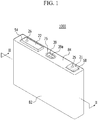
- FIG. 1 shows a perspective view of a rechargeable battery according to an exemplary embodiment
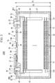
- FIG. 2 shows a cross-sectional view of the rechargeable battery illustrated in FIG. 1 taken along the line II-II of FIG. 1
- FIG. 3 shows a cross-sectional view of a rechargeable battery according to another exemplary embodiment taken along the line II-II of FIG. 1 .
- a rechargeable battery 1000 includes an electrode assembly 10, a case 27 for receiving and accommodating the electrode assembly 10, a cap assembly 30 coupled to the case 27 at an opening thereof (e.g., installed in the opening of the case 27), and an insulation member 800 for sealing the case 27 and the cap assembly 30.
- the rechargeable battery 1000 is illustrated as being a rectangular-shaped or square-shaped lithium ion secondary battery.
- the present invention is not restricted thereto, and the present invention may be applied to various types of batteries, such as a lithium polymer battery or a cylindrical battery.
- the electrode assembly 10 may be a jellyroll type that is spirally wound and includes a separator 13 arranged between a first electrode (e.g., a positive electrode) 11 and a second electrode (e.g., a negative electrode) 12.
- a first electrode e.g., a positive electrode
- a second electrode e.g., a negative electrode
- the positive electrode 11 and the negative electrode 12 each include a coated region, formed by coating an active material on a current collector made of a thin-plate metallic foil, and electrode uncoated regions 11a and 11b in which the active material is not coated.
- the coated region of the positive electrode 11 may be formed by coating an active material, such as a transition metal oxide, on the current collector made of a metal foil, such as aluminum
- the coated region of the negative electrode 12 may be formed by coating an active material, such as graphite or carbon, on the current collector made of a metal foil, such as copper or nickel.
- the positive uncoated region 11a is provided at one-side end of the positive electrode 11 in a length direction of the positive electrode 11, and the negative uncoated region 12a is provided at one-side end of the negative electrode 12 in a length direction of the negative electrode 12.
- the positive uncoated region 11a and the negative uncoated region 12a may be provided at opposite sides of the wound electrode assembly 10.
- the positive electrode 11 and the negative electrode 12 are spirally wound with the separator 13, that is an insulator, therebetween. More than one separator 13 may be included in the electrode assembly 10, and the positive electrode 11, the negative electrode 12, and the separator 13 may be alternately disposed (e.g., alternately stacked) and may be spirally wound.
- the present invention is not restricted to this, and the above-described electrode assembly 10 may be configured as a structure in which a plurality of sheets, including the positive electrode, the separator, and the negative electrode, are repeatedly stacked.
- the electrode assembly 10 may be received in (e.g., accommodated in) the case 27 together with an electrolyte solution.
- the electrolyte solution may include an organic solvent, such as EC, PC, DEC, EMC, and/or EMC, and a lithium salt, such as LiPF 6 and/or LiBF 4 .
- the electrolyte solution may be liquid, solid, or gel.
- the case 27 is substantially cuboidal and includes an opening at one side thereof.
- the case 27 may be made of a metal, such as aluminum.
- the cap assembly 30 includes a cap plate 31 coupled to (e.g., combined to) the case 27 to shut (e.g., to close and seal) the opening of the case 27, a positive terminal 21 protruding outside the cap plate 31 and electrically connected to the positive electrode 11, and a negative terminal 22 protruding outside the cap plate 31 and electrically connected to the negative electrode 12.
- the cap plate 31 has a plate shape extending in a direction and is coupled to the case 27 at the opening thereof (e.g., the cap plate 31 is fitted inside the opening of the case 27).
- the cap plate 31 includes an injection opening 32 (e.g., an injection hole) penetrating into the inside of the case 27 (e.g., extending through the cap plate 31) and a vent opening 34 (e.g., a vent hole).
- the injection opening 32 is used to inject the electrolyte solution, and after the electrolyte solution is injected into the case 27, a sealing stopper 38 is arranged in the injection opening 32 to close and seal the injection opening 32.
- the vent opening 34 includes a vent member 39 including a notch 39a such that the vent member 39 opens or bursts at a certain pressure (e.g., at a predetermined pressure).
- An embankment 75 (e.g., a ridge or protrusion) surrounds the vent member 39.
- the embankment 75 may protrude from an upper side or surface of the cap plate 31.
- the embankment 75 may be additionally provided on the cap plate 31 (e.g., the embankment 75 may be formed separately from the cap plate 31); however, it is not limited thereto, and the embankment 75 may be integrally formed with the cap plate 31.
- the cap plate 31 e.g., a portion of the cap plate 31 surrounding the vent member 39 may protrude upward and have a corresponding groove at a bottom side or surface of the cap plate 31 (e.g., the embankment 75 may be formed by pressing or stamping the cap plate 31 such that a groove corresponding to the embankment 75 is formed at the bottom side or surface of the cap plate 31).
- An upper end or surface of the embankment 75 and an upper end or surface of a first insulation member 82 may be coplanar.
- the positive terminal 21 and the negative terminal 22 are provided to protrude above a top (e.g., to protrude above an upper surface) of the cap plate 31.
- the positive terminal 21 is electrically connected to the positive electrode 11 with a current collecting tab 41 as a medium
- the negative terminal 22 is electrically connected to the negative electrode 12 with a current collecting tab 42 as a medium.
- a terminal connecting member 25 electrically connecting the positive terminal 21 and the current collecting tab 41 to each other is installed between the positive terminal 21 and the current collecting tab 41.
- the terminal connecting member 25 is inserted into an opening (e.g., a hole) provided in the positive terminal 21.
- a top of the terminal connecting member 25 is coupled to (e.g., fixed to) the positive terminal 21 by welding, and an end thereof is fixed to the current collecting tab 41 by welding.
- a gasket 59 is inserted into an opening in the cap plate 31 through which the terminal connecting member 25 passes and is arranged and seals between the terminal connecting member 25 and the cap plate 31.
- a connection plate 58 for electrically connecting the positive terminal 21 and the cap plate 31 to each other is provided between the positive terminal 21 and the cap plate 31.
- the terminal connecting member 25 is inserted into (e.g., is inserted through) the connection plate 58. Accordingly, the cap plate 31 and the case 27 are charged as the positive electrode 11 (e.g., the cap plate 31 and the case 27 are positively biased).
- a terminal connecting member 26 electrically connecting the negative terminal 22 and the current collecting tab 42 to each other is installed between the negative terminal 22 and the current collecting tab 42.
- the terminal connecting member 26 is inserted into an opening provided in the negative terminal 22.
- a top of the terminal connecting member 26 is fixed to the negative terminal 22 by welding, and a bottom thereof is fixed to the current collecting tab 42 by welding.
- a gasket 59 is inserted into an opening in the cap plate 31 through which the terminal connecting member 26 passes and is arranged and seals between the negative terminal 22 and the cap plate 31.
- An upper insulation member 54 is installed between and insulates the negative terminal 22 and the cap plate 31 from each other.
- the terminal connecting member 26 may be inserted into an opening (e.g., a hole) in the upper insulation member 54, and the upper insulation member 54 may surround an end of the negative terminal 22.
- a lower insulation member 43 for insulating the negative terminal 22 and the current collecting tab 42 from the cap plate 31 is installed below or under the cap plate 31.
- a short-circuit opening 37 (e.g., a short-circuit hole) is provided in the cap plate 31, and a short-circuit member 56 is provided in the short-circuit opening 37.
- the short-circuit member 56 has a curved portion that is curved downwardly in a convex manner (e.g., curved downwardly toward the electrode assembly 10) and an edge portion outside (e.g., surrounding) the curved portion that is fixed to the cap plate 31.
- the upper insulation member 54 may include an incised portion overlapping (e.g., over) the short-circuit opening 37, and the short-circuit member 56 overlaps the negative terminal 22 (e.g., the short-circuit member 56 is arranged below the negative terminal 22), which is exposed through the incised portion.
- the short-circuit member 56 is electrically connected to the cap plate 31, and it is configured to transform or deform when an internal pressure of the rechargeable battery 1000 increases (e.g., increases above a certain pressure), thereby causing a short circuit between the positive electrode and the negative electrode.
- an internal pressure of the rechargeable battery increases.
- a certain pressure e.g., a predetermined pressure
- the curved portion transforms or deforms to be convex upward, and the negative terminal 22 contacts the short-circuit member 56 to cause a short circuit.
- the negative terminal 22 may further include a protrusion 3 protruding toward the short-circuit member 56.
- the protrusion 3 is separated from (e.g., spaced from) the short-circuit member 56.
- the case 27 and the cap assembly 30 are surrounded by an insulation member 800.
- the insulation member 800 includes the first insulation member 82 surrounding the case 27 and a second insulation member 84 provided on the cap plate 31.
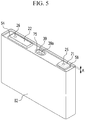
- FIG. 2 A further detailed description will now be provided with reference to FIG. 2 , FIG. 4 , and FIG. 5 .
- FIG. 4 and FIG. 5 show perspective views of the insulation member of the rechargeable battery according to an exemplary embodiment.
- the first insulation member 82 has a box shape including an internal space for receiving the case 27, and an opening is provided at a top of the first insulation member 82.
- the case 27 may be inserted inside the first insulation member 82 through the opening of the first insulation member 82.
- the case 27 includes and accommodates an electrode assembly 10, and a cap assembly 30 is coupled to the case 27 at the opening thereof.
- an end of the first insulation member 82 protrudes above the top of the case 27 (e.g., an upper end of the first insulation member 82 protrudes above an upper end of the case 27 and above an upper surface of the cap plate 31).
- a depth D1 of the internal space of the first insulation member 82 is greater than a length D2 of a side of the case 27.
- the first insulation member 82 includes a thermal bonding layer on an inner side thereof that is melted by heat and/or pressure and is attached to the case 27.
- the first insulation member 82 may be made of a material that shrinks when exposed to heat, and the first insulation member 82 may be attached to the case 27 by heat shrinking.
- the second insulation member 84 may be formed by coating a fluid insulation material and curing the insulation material by using light irradiation or heat treatment.
- the fluid insulation material is not as thick as the positive terminal 21 and the negative terminal 22 so that it does not cover the positive terminal 21 and the negative terminal 22.
- a height A of the extension may be the same as or greater than a thickness D3 of the second insulation member 84.
- the extension acts as an embankment to prevent the fluid insulation material of the second insulation member 84 from flowing off of the cap assembly when the fluid insulation material is coated thereon. Therefore, the thickness of the second insulation member 84 may be the same as or less than the height of the extension. Hence, a minimum height of the extension is advantageous for allowing for the second insulation member thick enough such that its ability to protect the cap plate remains guaranteed.
- the embankment 75 surrounding the vent member 39 is provided around the vent member 39 to prevent the insulation material from flowing into or on the vent member 39. Therefore, the vent member 39 is not covered by the second insulation member 84 but remains exposed.
- the insulation material When the insulation material is formed by coating a fluid material on the cap plate, the insulation material spreads to cover the cap plate. The insulation material spreads along an upper side or surface of the cap plate and contacts the extension of the first insulation member. The insulation material covers an area where the cap plate is coupled to (e.g., combined to) the case. The insulation material is cured to form the second insulation member while covering the area where the cap plate is coupled to the case.
- the second insulation member When the second insulation member is formed using the fluid insulation material and when the area where the cap plate is coupled to the case has a crack, the second insulation member fills the crack, thereby further improving the seal between the cap plate and the case (e.g., thereby improving a sealing force of the rechargeable battery).
- the insulation member When the insulation member is provided, a short circuit caused by condensation may be prevented, and permeation of moisture into a surface layer of the case is sufficiently controlled to prevent corrosion.
- the first insulation member may have the above-described box shape. However, it is not limited thereto, and it may be provided as a folded sheet, which will now be described with reference to FIGS. 6- 9 .
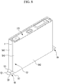
- FIGS. 6- 9 show a method for forming a first insulation member according to another exemplary embodiment.
- a battery assembly 101 and a first insulation member 82 are prepared, and the battery assembly 101 is provided on the first insulation member 82.
- the battery assembly 101 may be a battery assembly that is the same as or substantially similar to the battery assembly described above with respect to FIGS. 1 and 2 , and the battery assembly 101 is formed by coupling the cap assembly to the case, in which the electrode assembly is received, at the opening thereof.
- the first insulation member 82 is a sheet and has a pair of first folding lines S1, a pair of second folding line S2, a plurality of third folding lines S3, a pair of first incising lines Q1, and a pair of second incising lines Q2.
- the pair of first folding lines S1 are separated from (e.g., spaced from) each other by a distance (e.g., by a first distance or a predetermined distance) and extend in parallel.
- Each of the first folding lines S1 may be provided in parallel to a long side of a bottom side of the case.
- Each of the second folding lines S2 may be provided to cross the first folding line S1.
- the first incising lines Q1 and the second incising lines Q2 may be provided in parallel with the first folding lines S1, and a space between the first incising lines Q1 and a space between the second incising lines Q2 may be smaller than a space between the first folding lines S1.
- the first insulation member 82 may be partitioned into a first area, a second area, a third area, and a fourth area by the first and second folding lines S1 and S2, and portions of the first insulation member provided in the respective areas will be referred to as a first small area SA1, a second small area SA2, a third small area SA3, and a fourth small area SA4.
- the first incising lines Q1 and the second incising lines Q2 may be provided in the fourth small member SA4.
- the third folding lines S3 may extend toward crossing points at where corresponding ones of the first folding lines S1 cross ones of the second folding lines S2 from ends of the first incising lines Q1 and ends of the second incising lines Q2.
- the first insulation member 82 may be a polymer sheet including polyethylene terephthalate (PET) or a polyimide (PI), and an adhesive (e.g., an adhesive layer) may be provided on an inner side thereof.
- the first insulation member 82 may be attached to the battery assembly 101 by the adhesive.
- the battery assembly 101 is disposed on the first insulation member 82 when the first insulation member 82 is spread out (e.g., is in a flat state, before it is folded), and the battery assembly 101 is disposed on the first small member SA1. Edges of the bottom side of the battery assembly 101 may be disposed along the first folding lines S1 and the second folding lines S2. Long-side edges of the bottom side of the battery assembly 101 may be disposed along the first folding lines S1, and short-side edges thereof may be disposed along the second folding lines S2. For convenience of description, lateral sides of the battery assembly 101 extending from long-side edges thereof will be referred to as first lateral sides P1, and lateral sides of the battery assembly 101 extending from short-side edges thereof will be referred to as second lateral sides P2.
- the first insulation member 82 is folded along the pair of first folding lines S1 such that the second small area SA2 is provided on (e.g., contacts or is attached to) respective first lateral sides P1 (refer to FIG. 6 ) of the battery assembly 101.
- the first insulation member 82 is folded along the second folding lines S2 provided between the second small area SA2 and the third small area SA3 to allow the third small area SA3 to contact respective second lateral sides P2 (refer to FIG. 6 ) of the battery assembly 101.
- a width of the third small area SA3 may be greater than half the width of the second lateral side P2 such that edges of the third small area SA3 provided on the respective second lateral sides P2 of the battery assembly 101 may overlap each other to provide an overlapped portion F.
- the fourth small area SA4 is also folded along the third folding lines S3 to provide a finishing member 99.
- the incised portions Q1 and Q2 provided on the fourth small area SA4 allow the fourth small area SA4 to be easily folded along the third folding lines S3.
- the finishing member 99 is folded to overlap the battery assembly 101 (e.g., the finishing member 99 is folded to overlap a portion of the third small area SA3) and is thermally fused to be fixed thereto.
- the first insulation member 82 may be configured to surround the edges of the battery assembly 101 and to be folded around and attached to the battery assembly 101, thereby easily sealing various sizes of battery assemblies.
Landscapes
- Chemical & Material Sciences (AREA)
- Chemical Kinetics & Catalysis (AREA)
- Electrochemistry (AREA)
- General Chemical & Material Sciences (AREA)
- Engineering & Computer Science (AREA)
- Manufacturing & Machinery (AREA)
- Sealing Battery Cases Or Jackets (AREA)
- Connection Of Batteries Or Terminals (AREA)
Claims (8)
- Batterie rechargeable (1000, 1002) comprenant :un ensemble d'électrodes (10) comprenant une première électrode (11), un séparateur (13), et une deuxième électrode (12) ;un boîtier (27) logeant l'ensemble d'électrodes (10), et comportant une ouverture d'un côté de celui-ci pour recevoir l'ensemble d'électrodes (10) ;un ensemble de recouvrement (30) accouplé au boîtier (27) au niveau de l'ouverture, où l'ensemble de recouvrement (30) comprend une plaque de recouvrement (31), où la plaque de recouvrement (31) comprend un élément d'évent (39) ;la batterie rechargeable (1000, 1002) comprenant en outre :un premier élément isolant (82) entourant le boîtier (27), une partie d'extension du premier élément isolant s'étendant d'une hauteur (A) au-dessus de l'ensemble de recouvrement (30) ; etun deuxième élément isolant (84) sur l'ensemble de recouvrement (30) et en contact avec la partie d'extension du premier élément isolant (82), le deuxième élément isolant (82) étant une couche revêtue, où l'élément d'évent (39) est exposé à travers le deuxième élément isolant (84),dans laquelle la plaque de recouvrement (31) comprend en outre un rebord (75) autour d'une périphérie de l'élément d'évent (39) ayant une hauteur qui est suffisante pour empêcher l'écoulement du matériau isolant du deuxième élément isolant (84) dans ou sur l'élément d'évent (39).
- Batterie rechargeable selon la revendication 1, dans laquelle le deuxième élément isolant (82) est en contact avec un côté intérieur de la partie d'extension.
- Batterie rechargeable selon l'une quelconque des revendications précédentes, dans laquelle une extrémité supérieure de la partie d'extension et une extrémité supérieure du rebord (75) ont sensiblement la même hauteur (A) au-dessus de la plaque de recouvrement (31).
- Batterie rechargeable (1002) selon l'une quelconque des revendications précédentes, dans laquelle une rainure correspondant au rebord (75) est formée au niveau d'une surface inférieure de la plaque de recouvrement (31).
- Batterie rechargeable selon l'une quelconque des revendications 1 à 4, dans laquelle la plaque de recouvrement (31) comprend en outre :une première borne d'électrode (21) sur la plaque de recouvrement (31), et connectée électriquement à la première électrode (11) par l'intermédiaire d'un premier élément de connexion de borne (25) ;une deuxième borne d'électrode (22) sur la plaque de recouvrement (31), et connectée électriquement à la deuxième électrode (12) par l'intermédiaire d'un deuxième élément de connexion de borne (26) ; etun élément isolant supérieur (54) entre la deuxième borne d'électrode (22) et le boîtier (27).
- Batterie rechargeable selon la revendication 5, dans laquelle une épaisseur (D3) du deuxième élément isolant (84) est égale ou inférieure à la hauteur (A) de l'extension de l'élément isolant supérieur (54).
- Batterie rechargeable selon l'une quelconque des revendications précédentes, dans laquelle le premier élément isolant (82) est une feuille et, lorsque le premier élément isolant (82) entoure le boîtier (27), le premier élément isolant (82) a une partie superposée (F) sur un côté latéral du boîtier (27) où le premier élément isolant (82) se superpose à lui-même.
- Batterie rechargeable selon l'une quelconque des revendications précédentes, dans laquelle le premier élément isolant (82) comprend une couche de liaison thermique configurée pour être fondue d'un côté de celle-ci faisant face au boîtier (27).
Applications Claiming Priority (1)
| Application Number | Priority Date | Filing Date | Title |
|---|---|---|---|
| KR1020150165716A KR102515095B1 (ko) | 2015-11-25 | 2015-11-25 | 이차 전지 |
Publications (2)
| Publication Number | Publication Date |
|---|---|
| EP3174126A1 EP3174126A1 (fr) | 2017-05-31 |
| EP3174126B1 true EP3174126B1 (fr) | 2019-09-04 |
Family
ID=56413536
Family Applications (1)
| Application Number | Title | Priority Date | Filing Date |
|---|---|---|---|
| EP16179587.7A Active EP3174126B1 (fr) | 2015-11-25 | 2016-07-15 | Batterie rechargeable |
Country Status (4)
| Country | Link |
|---|---|
| US (1) | US9966579B2 (fr) |
| EP (1) | EP3174126B1 (fr) |
| KR (1) | KR102515095B1 (fr) |
| CN (1) | CN106803553B (fr) |
Cited By (2)
| Publication number | Priority date | Publication date | Assignee | Title |
|---|---|---|---|---|
| EP4625641A1 (fr) * | 2024-03-26 | 2025-10-01 | Samsung Sdi Co., Ltd. | Élément de batterie, module de batterie comprenant l'élément de batterie et bloc-batterie comprenant le module de batterie |
| EP4712218A1 (fr) * | 2024-09-13 | 2026-03-18 | Samsung Sdi Co., Ltd. | Élément de batterie et module de batterie le comprenant |
Families Citing this family (20)
| Publication number | Priority date | Publication date | Assignee | Title |
|---|---|---|---|---|
| KR102139065B1 (ko) * | 2017-02-13 | 2020-07-29 | 주식회사 엘지화학 | 무기물 코팅부를 포함하고 있는 원통형 전지셀 |
| JP7031300B2 (ja) * | 2017-12-27 | 2022-03-08 | 株式会社Gsユアサ | 蓄電素子及び蓄電装置 |
| US10673038B2 (en) | 2018-03-23 | 2020-06-02 | Chongqing Jinkang New Energy Vehicle Co., Ltd. | Battery cells for battery packs in electric vehicles |
| KR102775448B1 (ko) * | 2019-01-31 | 2025-03-05 | 삼성에스디아이 주식회사 | 이차 전지 |
| KR102793400B1 (ko) | 2019-04-19 | 2025-04-09 | 삼성에스디아이 주식회사 | 이차 전지 |
| KR102786074B1 (ko) | 2019-07-04 | 2025-03-26 | 삼성에스디아이 주식회사 | 이차 전지 |
| CN209880668U (zh) * | 2019-07-25 | 2019-12-31 | 宁德时代新能源科技股份有限公司 | 顶盖组件及二次电池 |
| KR20220105018A (ko) * | 2021-01-19 | 2022-07-26 | 삼성에스디아이 주식회사 | 이차 전지 |
| CN215989141U (zh) * | 2021-05-27 | 2022-03-08 | 宁德时代新能源科技股份有限公司 | 电池单体、电池以及用电装置 |
| JP7596401B2 (ja) * | 2021-07-27 | 2024-12-09 | 香港時代新能源科技有限公司 | 絶縁膜、電池セル、電池及び電力消費機器 |
| CN116648813A (zh) * | 2021-08-27 | 2023-08-25 | 宁德时代新能源科技股份有限公司 | 电池单体、电池及用电装置 |
| KR20230111398A (ko) * | 2022-01-18 | 2023-07-25 | 삼성에스디아이 주식회사 | 이차 전지 및 그의 제조 방법 |
| CN117413402A (zh) * | 2022-05-16 | 2024-01-16 | 宁德时代新能源科技股份有限公司 | 端盖、电池单体、电池及用电设备 |
| US20240030523A1 (en) * | 2022-07-25 | 2024-01-25 | Aesc Japan Ltd. | Battery cell |
| US20240039092A1 (en) * | 2022-07-28 | 2024-02-01 | Aesc Japan Ltd. | Battery cell |
| US20240039091A1 (en) * | 2022-07-28 | 2024-02-01 | Aesc Japan Ltd. | Battery cell |
| CN116742220A (zh) * | 2023-02-09 | 2023-09-12 | 深圳海辰储能控制技术有限公司 | 外包膜、储能装置和用电设备 |
| EP4481901A1 (fr) * | 2023-06-21 | 2024-12-25 | Automotive Cells Company SE | Procédé de dépôt d'une couche d'isolation électrique |
| US20250087824A1 (en) * | 2023-09-11 | 2025-03-13 | Sk On Co., Ltd. | Battery cell |
| KR20250038953A (ko) * | 2023-09-13 | 2025-03-20 | 삼성에스디아이 주식회사 | 이차 전지 |
Family Cites Families (10)
| Publication number | Priority date | Publication date | Assignee | Title |
|---|---|---|---|---|
| US5432017A (en) * | 1992-09-14 | 1995-07-11 | Motorola, Inc. | Battery pack and method of forming same |
| US7736799B1 (en) * | 2009-07-17 | 2010-06-15 | Tesla Motors, Inc. | Method and apparatus for maintaining cell wall integrity during thermal runaway using an outer layer of intumescent material |
| JP5919777B2 (ja) | 2011-01-31 | 2016-05-18 | 株式会社Gsユアサ | 蓄電素子 |
| KR101438439B1 (ko) | 2012-02-07 | 2014-09-05 | 주식회사 엘지화학 | 신규한 구조의 내장형 전지셀 |
| KR101397029B1 (ko) * | 2012-09-13 | 2014-05-20 | 삼성에스디아이 주식회사 | 배터리 셀 조립체, 이를 구비하는 배터리 팩, 배터리 셀 조립체의 제조방법 및 배터리 셀 조립체의 제조를 위한 지그 조립체 |
| KR20140094205A (ko) * | 2013-01-21 | 2014-07-30 | 삼성에스디아이 주식회사 | 이차 전지 |
| KR20140101228A (ko) | 2013-02-08 | 2014-08-19 | 삼성에스디아이 주식회사 | 전지 모듈 |
| KR20140121205A (ko) * | 2013-04-05 | 2014-10-15 | 삼성에스디아이 주식회사 | 이차 전지 및 이의 외면을 절연시키는 방법 |
| KR20150039290A (ko) | 2013-10-02 | 2015-04-10 | 주식회사 엘지화학 | 경화성 물질로 코팅되어 있는 밀봉부를 포함하는 휘어진 형상의 파우치형 리튬 이차전지 |
| KR20140099846A (ko) | 2014-07-04 | 2014-08-13 | 주식회사 엘지화학 | 신규한 구조의 내장형 전지셀 |
-
2015
- 2015-11-25 KR KR1020150165716A patent/KR102515095B1/ko active Active
-
2016
- 2016-06-28 US US15/196,002 patent/US9966579B2/en active Active
- 2016-07-15 EP EP16179587.7A patent/EP3174126B1/fr active Active
- 2016-08-22 CN CN201610700809.4A patent/CN106803553B/zh active Active
Non-Patent Citations (1)
| Title |
|---|
| None * |
Cited By (2)
| Publication number | Priority date | Publication date | Assignee | Title |
|---|---|---|---|---|
| EP4625641A1 (fr) * | 2024-03-26 | 2025-10-01 | Samsung Sdi Co., Ltd. | Élément de batterie, module de batterie comprenant l'élément de batterie et bloc-batterie comprenant le module de batterie |
| EP4712218A1 (fr) * | 2024-09-13 | 2026-03-18 | Samsung Sdi Co., Ltd. | Élément de batterie et module de batterie le comprenant |
Also Published As
| Publication number | Publication date |
|---|---|
| CN106803553B (zh) | 2021-05-14 |
| KR20170060941A (ko) | 2017-06-02 |
| KR102515095B1 (ko) | 2023-03-27 |
| CN106803553A (zh) | 2017-06-06 |
| EP3174126A1 (fr) | 2017-05-31 |
| US9966579B2 (en) | 2018-05-08 |
| US20170149030A1 (en) | 2017-05-25 |
Similar Documents
| Publication | Publication Date | Title |
|---|---|---|
| EP3174126B1 (fr) | Batterie rechargeable | |
| EP3503250B1 (fr) | Batterie rechargeable | |
| US10693121B2 (en) | Rechargeable battery | |
| US20090162749A1 (en) | Electrode tab for secondary battery and secondary battery using the same | |
| US9287534B2 (en) | Rechargeable battery | |
| KR20130004041A (ko) | 이차전지 | |
| US12573696B2 (en) | Secondary battery | |
| KR102571182B1 (ko) | 이차 전지 | |
| US20230216152A1 (en) | Secondary battery | |
| US20200313147A1 (en) | Secondary battery | |
| KR102425219B1 (ko) | 이차 전지 | |
| EP3086382B1 (fr) | Batterie rechargeable | |
| US20240106019A1 (en) | Secondary battery | |
| EP3029756B1 (fr) | Batterie rechargeable | |
| US20260074399A1 (en) | Secondary battery | |
| US20240106085A1 (en) | Secondary battery | |
| US9768420B2 (en) | Rechargeable battery | |
| US10424817B2 (en) | Pouch type rechargeable battery | |
| EP3001481B1 (fr) | Batterie rechargeable |
Legal Events
| Date | Code | Title | Description |
|---|---|---|---|
| PUAI | Public reference made under article 153(3) epc to a published international application that has entered the european phase |
Free format text: ORIGINAL CODE: 0009012 |
|
| STAA | Information on the status of an ep patent application or granted ep patent |
Free format text: STATUS: THE APPLICATION HAS BEEN PUBLISHED |
|
| AK | Designated contracting states |
Kind code of ref document: A1 Designated state(s): AL AT BE BG CH CY CZ DE DK EE ES FI FR GB GR HR HU IE IS IT LI LT LU LV MC MK MT NL NO PL PT RO RS SE SI SK SM TR |
|
| AX | Request for extension of the european patent |
Extension state: BA ME |
|
| STAA | Information on the status of an ep patent application or granted ep patent |
Free format text: STATUS: REQUEST FOR EXAMINATION WAS MADE |
|
| 17P | Request for examination filed |
Effective date: 20171122 |
|
| RBV | Designated contracting states (corrected) |
Designated state(s): AL AT BE BG CH CY CZ DE DK EE ES FI FR GB GR HR HU IE IS IT LI LT LU LV MC MK MT NL NO PL PT RO RS SE SI SK SM TR |
|
| STAA | Information on the status of an ep patent application or granted ep patent |
Free format text: STATUS: EXAMINATION IS IN PROGRESS |
|
| 17Q | First examination report despatched |
Effective date: 20180213 |
|
| GRAP | Despatch of communication of intention to grant a patent |
Free format text: ORIGINAL CODE: EPIDOSNIGR1 |
|
| STAA | Information on the status of an ep patent application or granted ep patent |
Free format text: STATUS: GRANT OF PATENT IS INTENDED |
|
| RIC1 | Information provided on ipc code assigned before grant |
Ipc: H01M 2/12 20060101ALN20190206BHEP Ipc: H01M 2/04 20060101ALI20190206BHEP Ipc: H01M 2/02 20060101AFI20190206BHEP Ipc: H01M 2/10 20060101ALI20190206BHEP |
|
| INTG | Intention to grant announced |
Effective date: 20190226 |
|
| GRAS | Grant fee paid |
Free format text: ORIGINAL CODE: EPIDOSNIGR3 |
|
| GRAA | (expected) grant |
Free format text: ORIGINAL CODE: 0009210 |
|
| STAA | Information on the status of an ep patent application or granted ep patent |
Free format text: STATUS: THE PATENT HAS BEEN GRANTED |
|
| AK | Designated contracting states |
Kind code of ref document: B1 Designated state(s): AL AT BE BG CH CY CZ DE DK EE ES FI FR GB GR HR HU IE IS IT LI LT LU LV MC MK MT NL NO PL PT RO RS SE SI SK SM TR |
|
| REG | Reference to a national code |
Ref country code: GB Ref legal event code: FG4D |
|
| REG | Reference to a national code |
Ref country code: CH Ref legal event code: EP |
|
| REG | Reference to a national code |
Ref country code: AT Ref legal event code: REF Ref document number: 1176623 Country of ref document: AT Kind code of ref document: T Effective date: 20190915 |
|
| REG | Reference to a national code |
Ref country code: DE Ref legal event code: R096 Ref document number: 602016019766 Country of ref document: DE |
|
| REG | Reference to a national code |
Ref country code: IE Ref legal event code: FG4D |
|
| REG | Reference to a national code |
Ref country code: NL Ref legal event code: MP Effective date: 20190904 |
|
| REG | Reference to a national code |
Ref country code: LT Ref legal event code: MG4D |
|
| PG25 | Lapsed in a contracting state [announced via postgrant information from national office to epo] |
Ref country code: BG Free format text: LAPSE BECAUSE OF FAILURE TO SUBMIT A TRANSLATION OF THE DESCRIPTION OR TO PAY THE FEE WITHIN THE PRESCRIBED TIME-LIMIT Effective date: 20191204 Ref country code: NO Free format text: LAPSE BECAUSE OF FAILURE TO SUBMIT A TRANSLATION OF THE DESCRIPTION OR TO PAY THE FEE WITHIN THE PRESCRIBED TIME-LIMIT Effective date: 20191204 Ref country code: FI Free format text: LAPSE BECAUSE OF FAILURE TO SUBMIT A TRANSLATION OF THE DESCRIPTION OR TO PAY THE FEE WITHIN THE PRESCRIBED TIME-LIMIT Effective date: 20190904 Ref country code: LT Free format text: LAPSE BECAUSE OF FAILURE TO SUBMIT A TRANSLATION OF THE DESCRIPTION OR TO PAY THE FEE WITHIN THE PRESCRIBED TIME-LIMIT Effective date: 20190904 Ref country code: SE Free format text: LAPSE BECAUSE OF FAILURE TO SUBMIT A TRANSLATION OF THE DESCRIPTION OR TO PAY THE FEE WITHIN THE PRESCRIBED TIME-LIMIT Effective date: 20190904 Ref country code: HR Free format text: LAPSE BECAUSE OF FAILURE TO SUBMIT A TRANSLATION OF THE DESCRIPTION OR TO PAY THE FEE WITHIN THE PRESCRIBED TIME-LIMIT Effective date: 20190904 |
|
| PG25 | Lapsed in a contracting state [announced via postgrant information from national office to epo] |
Ref country code: AL Free format text: LAPSE BECAUSE OF FAILURE TO SUBMIT A TRANSLATION OF THE DESCRIPTION OR TO PAY THE FEE WITHIN THE PRESCRIBED TIME-LIMIT Effective date: 20190904 Ref country code: LV Free format text: LAPSE BECAUSE OF FAILURE TO SUBMIT A TRANSLATION OF THE DESCRIPTION OR TO PAY THE FEE WITHIN THE PRESCRIBED TIME-LIMIT Effective date: 20190904 Ref country code: RS Free format text: LAPSE BECAUSE OF FAILURE TO SUBMIT A TRANSLATION OF THE DESCRIPTION OR TO PAY THE FEE WITHIN THE PRESCRIBED TIME-LIMIT Effective date: 20190904 Ref country code: GR Free format text: LAPSE BECAUSE OF FAILURE TO SUBMIT A TRANSLATION OF THE DESCRIPTION OR TO PAY THE FEE WITHIN THE PRESCRIBED TIME-LIMIT Effective date: 20191205 Ref country code: ES Free format text: LAPSE BECAUSE OF FAILURE TO SUBMIT A TRANSLATION OF THE DESCRIPTION OR TO PAY THE FEE WITHIN THE PRESCRIBED TIME-LIMIT Effective date: 20190904 |
|
| REG | Reference to a national code |
Ref country code: AT Ref legal event code: MK05 Ref document number: 1176623 Country of ref document: AT Kind code of ref document: T Effective date: 20190904 |
|
| PG25 | Lapsed in a contracting state [announced via postgrant information from national office to epo] |
Ref country code: IT Free format text: LAPSE BECAUSE OF FAILURE TO SUBMIT A TRANSLATION OF THE DESCRIPTION OR TO PAY THE FEE WITHIN THE PRESCRIBED TIME-LIMIT Effective date: 20190904 Ref country code: PT Free format text: LAPSE BECAUSE OF FAILURE TO SUBMIT A TRANSLATION OF THE DESCRIPTION OR TO PAY THE FEE WITHIN THE PRESCRIBED TIME-LIMIT Effective date: 20200106 Ref country code: AT Free format text: LAPSE BECAUSE OF FAILURE TO SUBMIT A TRANSLATION OF THE DESCRIPTION OR TO PAY THE FEE WITHIN THE PRESCRIBED TIME-LIMIT Effective date: 20190904 Ref country code: EE Free format text: LAPSE BECAUSE OF FAILURE TO SUBMIT A TRANSLATION OF THE DESCRIPTION OR TO PAY THE FEE WITHIN THE PRESCRIBED TIME-LIMIT Effective date: 20190904 Ref country code: PL Free format text: LAPSE BECAUSE OF FAILURE TO SUBMIT A TRANSLATION OF THE DESCRIPTION OR TO PAY THE FEE WITHIN THE PRESCRIBED TIME-LIMIT Effective date: 20190904 Ref country code: NL Free format text: LAPSE BECAUSE OF FAILURE TO SUBMIT A TRANSLATION OF THE DESCRIPTION OR TO PAY THE FEE WITHIN THE PRESCRIBED TIME-LIMIT Effective date: 20190904 Ref country code: RO Free format text: LAPSE BECAUSE OF FAILURE TO SUBMIT A TRANSLATION OF THE DESCRIPTION OR TO PAY THE FEE WITHIN THE PRESCRIBED TIME-LIMIT Effective date: 20190904 |
|
| PG25 | Lapsed in a contracting state [announced via postgrant information from national office to epo] |
Ref country code: CZ Free format text: LAPSE BECAUSE OF FAILURE TO SUBMIT A TRANSLATION OF THE DESCRIPTION OR TO PAY THE FEE WITHIN THE PRESCRIBED TIME-LIMIT Effective date: 20190904 Ref country code: SM Free format text: LAPSE BECAUSE OF FAILURE TO SUBMIT A TRANSLATION OF THE DESCRIPTION OR TO PAY THE FEE WITHIN THE PRESCRIBED TIME-LIMIT Effective date: 20190904 Ref country code: SK Free format text: LAPSE BECAUSE OF FAILURE TO SUBMIT A TRANSLATION OF THE DESCRIPTION OR TO PAY THE FEE WITHIN THE PRESCRIBED TIME-LIMIT Effective date: 20190904 Ref country code: IS Free format text: LAPSE BECAUSE OF FAILURE TO SUBMIT A TRANSLATION OF THE DESCRIPTION OR TO PAY THE FEE WITHIN THE PRESCRIBED TIME-LIMIT Effective date: 20200224 |
|
| REG | Reference to a national code |
Ref country code: DE Ref legal event code: R097 Ref document number: 602016019766 Country of ref document: DE |
|
| PLBE | No opposition filed within time limit |
Free format text: ORIGINAL CODE: 0009261 |
|
| STAA | Information on the status of an ep patent application or granted ep patent |
Free format text: STATUS: NO OPPOSITION FILED WITHIN TIME LIMIT |
|
| PG2D | Information on lapse in contracting state deleted |
Ref country code: IS |
|
| PG25 | Lapsed in a contracting state [announced via postgrant information from national office to epo] |
Ref country code: DK Free format text: LAPSE BECAUSE OF FAILURE TO SUBMIT A TRANSLATION OF THE DESCRIPTION OR TO PAY THE FEE WITHIN THE PRESCRIBED TIME-LIMIT Effective date: 20190904 Ref country code: IS Free format text: LAPSE BECAUSE OF FAILURE TO SUBMIT A TRANSLATION OF THE DESCRIPTION OR TO PAY THE FEE WITHIN THE PRESCRIBED TIME-LIMIT Effective date: 20200105 |
|
| 26N | No opposition filed |
Effective date: 20200605 |
|
| PG25 | Lapsed in a contracting state [announced via postgrant information from national office to epo] |
Ref country code: SI Free format text: LAPSE BECAUSE OF FAILURE TO SUBMIT A TRANSLATION OF THE DESCRIPTION OR TO PAY THE FEE WITHIN THE PRESCRIBED TIME-LIMIT Effective date: 20190904 |
|
| REG | Reference to a national code |
Ref country code: DE Ref legal event code: R079 Ref document number: 602016019766 Country of ref document: DE Free format text: PREVIOUS MAIN CLASS: H01M0002020000 Ipc: H01M0050100000 |
|
| PG25 | Lapsed in a contracting state [announced via postgrant information from national office to epo] |
Ref country code: MC Free format text: LAPSE BECAUSE OF FAILURE TO SUBMIT A TRANSLATION OF THE DESCRIPTION OR TO PAY THE FEE WITHIN THE PRESCRIBED TIME-LIMIT Effective date: 20190904 |
|
| REG | Reference to a national code |
Ref country code: CH Ref legal event code: PL |
|
| REG | Reference to a national code |
Ref country code: BE Ref legal event code: MM Effective date: 20200731 |
|
| PG25 | Lapsed in a contracting state [announced via postgrant information from national office to epo] |
Ref country code: LU Free format text: LAPSE BECAUSE OF NON-PAYMENT OF DUE FEES Effective date: 20200715 Ref country code: LI Free format text: LAPSE BECAUSE OF NON-PAYMENT OF DUE FEES Effective date: 20200731 Ref country code: CH Free format text: LAPSE BECAUSE OF NON-PAYMENT OF DUE FEES Effective date: 20200731 |
|
| PG25 | Lapsed in a contracting state [announced via postgrant information from national office to epo] |
Ref country code: BE Free format text: LAPSE BECAUSE OF NON-PAYMENT OF DUE FEES Effective date: 20200731 |
|
| PG25 | Lapsed in a contracting state [announced via postgrant information from national office to epo] |
Ref country code: IE Free format text: LAPSE BECAUSE OF NON-PAYMENT OF DUE FEES Effective date: 20200715 |
|
| PG25 | Lapsed in a contracting state [announced via postgrant information from national office to epo] |
Ref country code: TR Free format text: LAPSE BECAUSE OF FAILURE TO SUBMIT A TRANSLATION OF THE DESCRIPTION OR TO PAY THE FEE WITHIN THE PRESCRIBED TIME-LIMIT Effective date: 20190904 Ref country code: MT Free format text: LAPSE BECAUSE OF FAILURE TO SUBMIT A TRANSLATION OF THE DESCRIPTION OR TO PAY THE FEE WITHIN THE PRESCRIBED TIME-LIMIT Effective date: 20190904 Ref country code: CY Free format text: LAPSE BECAUSE OF FAILURE TO SUBMIT A TRANSLATION OF THE DESCRIPTION OR TO PAY THE FEE WITHIN THE PRESCRIBED TIME-LIMIT Effective date: 20190904 |
|
| PG25 | Lapsed in a contracting state [announced via postgrant information from national office to epo] |
Ref country code: MK Free format text: LAPSE BECAUSE OF FAILURE TO SUBMIT A TRANSLATION OF THE DESCRIPTION OR TO PAY THE FEE WITHIN THE PRESCRIBED TIME-LIMIT Effective date: 20190904 |
|
| REG | Reference to a national code |
Ref country code: FR Ref legal event code: PLFP Year of fee payment: 7 |
|
| P01 | Opt-out of the competence of the unified patent court (upc) registered |
Effective date: 20230528 |
|
| PGFP | Annual fee paid to national office [announced via postgrant information from national office to epo] |
Ref country code: GB Payment date: 20250626 Year of fee payment: 10 |
|
| PGFP | Annual fee paid to national office [announced via postgrant information from national office to epo] |
Ref country code: FR Payment date: 20250623 Year of fee payment: 10 |
|
| PGFP | Annual fee paid to national office [announced via postgrant information from national office to epo] |
Ref country code: DE Payment date: 20250624 Year of fee payment: 10 |