EP3174183A1 - Machine électrique - Google Patents
Machine électrique Download PDFInfo
- Publication number
- EP3174183A1 EP3174183A1 EP16195302.1A EP16195302A EP3174183A1 EP 3174183 A1 EP3174183 A1 EP 3174183A1 EP 16195302 A EP16195302 A EP 16195302A EP 3174183 A1 EP3174183 A1 EP 3174183A1
- Authority
- EP
- European Patent Office
- Prior art keywords
- insert
- electric machine
- stator
- support structure
- laminated core
- Prior art date
- Legal status (The legal status is an assumption and is not a legal conclusion. Google has not performed a legal analysis and makes no representation as to the accuracy of the status listed.)
- Granted
Links
- 230000004907 flux Effects 0.000 claims abstract description 7
- 238000001816 cooling Methods 0.000 claims description 31
- 229910052751 metal Inorganic materials 0.000 claims description 13
- 239000002184 metal Substances 0.000 claims description 13
- 238000003475 lamination Methods 0.000 claims 3
- 238000004804 winding Methods 0.000 description 31
- 230000005291 magnetic effect Effects 0.000 description 27
- 238000004519 manufacturing process Methods 0.000 description 15
- XEEYBQQBJWHFJM-UHFFFAOYSA-N Iron Chemical compound [Fe] XEEYBQQBJWHFJM-UHFFFAOYSA-N 0.000 description 6
- 238000000034 method Methods 0.000 description 4
- 238000004026 adhesive bonding Methods 0.000 description 3
- 229910052782 aluminium Inorganic materials 0.000 description 3
- XAGFODPZIPBFFR-UHFFFAOYSA-N aluminium Chemical compound [Al] XAGFODPZIPBFFR-UHFFFAOYSA-N 0.000 description 3
- 230000008569 process Effects 0.000 description 3
- 238000005245 sintering Methods 0.000 description 3
- 238000003466 welding Methods 0.000 description 3
- RYGMFSIKBFXOCR-UHFFFAOYSA-N Copper Chemical compound [Cu] RYGMFSIKBFXOCR-UHFFFAOYSA-N 0.000 description 2
- 239000002131 composite material Substances 0.000 description 2
- 229910052802 copper Inorganic materials 0.000 description 2
- 239000010949 copper Substances 0.000 description 2
- 238000013461 design Methods 0.000 description 2
- 230000003993 interaction Effects 0.000 description 2
- 229910052742 iron Inorganic materials 0.000 description 2
- 239000000696 magnetic material Substances 0.000 description 2
- 239000000463 material Substances 0.000 description 2
- 239000000843 powder Substances 0.000 description 2
- 238000007493 shaping process Methods 0.000 description 2
- 230000001360 synchronised effect Effects 0.000 description 2
- 229910000859 α-Fe Inorganic materials 0.000 description 2
- 229910000838 Al alloy Inorganic materials 0.000 description 1
- 241001272720 Medialuna californiensis Species 0.000 description 1
- 239000000853 adhesive Substances 0.000 description 1
- 230000001070 adhesive effect Effects 0.000 description 1
- 230000004323 axial length Effects 0.000 description 1
- 239000011248 coating agent Substances 0.000 description 1
- 238000000576 coating method Methods 0.000 description 1
- 238000010276 construction Methods 0.000 description 1
- 239000002826 coolant Substances 0.000 description 1
- 239000000110 cooling liquid Substances 0.000 description 1
- 238000012937 correction Methods 0.000 description 1
- 238000011161 development Methods 0.000 description 1
- 230000018109 developmental process Effects 0.000 description 1
- 238000005553 drilling Methods 0.000 description 1
- 230000005294 ferromagnetic effect Effects 0.000 description 1
- 239000003302 ferromagnetic material Substances 0.000 description 1
- 239000003292 glue Substances 0.000 description 1
- 238000010438 heat treatment Methods 0.000 description 1
- 230000004048 modification Effects 0.000 description 1
- 238000012986 modification Methods 0.000 description 1
- 230000035699 permeability Effects 0.000 description 1
- 238000004080 punching Methods 0.000 description 1
- 238000005096 rolling process Methods 0.000 description 1
- 238000005476 soldering Methods 0.000 description 1
- 238000003860 storage Methods 0.000 description 1
- 239000002699 waste material Substances 0.000 description 1
Images

Classifications
-
- H—ELECTRICITY
- H02—GENERATION; CONVERSION OR DISTRIBUTION OF ELECTRIC POWER
- H02K—DYNAMO-ELECTRIC MACHINES
- H02K1/00—Details of the magnetic circuit
- H02K1/06—Details of the magnetic circuit characterised by the shape, form or construction
- H02K1/12—Stationary parts of the magnetic circuit
- H02K1/18—Means for mounting or fastening magnetic stationary parts on to, or to, the stator structures
- H02K1/182—Means for mounting or fastening magnetic stationary parts on to, or to, the stator structures to stators axially facing the rotor, i.e. with axial or conical air gap
-
- H—ELECTRICITY
- H02—GENERATION; CONVERSION OR DISTRIBUTION OF ELECTRIC POWER
- H02K—DYNAMO-ELECTRIC MACHINES
- H02K1/00—Details of the magnetic circuit
- H02K1/06—Details of the magnetic circuit characterised by the shape, form or construction
- H02K1/12—Stationary parts of the magnetic circuit
- H02K1/14—Stator cores with salient poles
- H02K1/141—Stator cores with salient poles consisting of C-shaped cores
-
- H—ELECTRICITY
- H02—GENERATION; CONVERSION OR DISTRIBUTION OF ELECTRIC POWER
- H02K—DYNAMO-ELECTRIC MACHINES
- H02K1/00—Details of the magnetic circuit
- H02K1/06—Details of the magnetic circuit characterised by the shape, form or construction
- H02K1/12—Stationary parts of the magnetic circuit
- H02K1/14—Stator cores with salient poles
- H02K1/146—Stator cores with salient poles consisting of a generally annular yoke with salient poles
- H02K1/148—Sectional cores
-
- H—ELECTRICITY
- H02—GENERATION; CONVERSION OR DISTRIBUTION OF ELECTRIC POWER
- H02K—DYNAMO-ELECTRIC MACHINES
- H02K1/00—Details of the magnetic circuit
- H02K1/06—Details of the magnetic circuit characterised by the shape, form or construction
- H02K1/12—Stationary parts of the magnetic circuit
- H02K1/18—Means for mounting or fastening magnetic stationary parts on to, or to, the stator structures
-
- H—ELECTRICITY
- H02—GENERATION; CONVERSION OR DISTRIBUTION OF ELECTRIC POWER
- H02K—DYNAMO-ELECTRIC MACHINES
- H02K21/00—Synchronous motors having permanent magnets; Synchronous generators having permanent magnets
- H02K21/12—Synchronous motors having permanent magnets; Synchronous generators having permanent magnets with stationary armatures and rotating magnets
- H02K21/24—Synchronous motors having permanent magnets; Synchronous generators having permanent magnets with stationary armatures and rotating magnets with magnets axially facing the armatures, e.g. hub-type cycle dynamos
-
- H—ELECTRICITY
- H02—GENERATION; CONVERSION OR DISTRIBUTION OF ELECTRIC POWER
- H02K—DYNAMO-ELECTRIC MACHINES
- H02K3/00—Details of windings
- H02K3/46—Fastening of windings on the stator or rotor structure
-
- H—ELECTRICITY
- H02—GENERATION; CONVERSION OR DISTRIBUTION OF ELECTRIC POWER
- H02K—DYNAMO-ELECTRIC MACHINES
- H02K9/00—Arrangements for cooling or ventilating
- H02K9/22—Arrangements for cooling or ventilating by solid heat conducting material embedded in, or arranged in contact with, the stator or rotor, e.g. heat bridges
- H02K9/227—Heat sinks
Definitions
- the invention relates to an electric machine with a rotor rotatably mounted about a machine axis, and with a stator.
- the electric machine is in particular an axial flow motor.
- Electric motors which are designed for example as wheel hub motors.
- the electric motors are designed comparatively compact and have a comparatively low weight.
- axial flow motors which usually have a number of electrical windings, which are arranged parallel to the axis of rotation of a rotor and around it to form a distance.
- electrical windings in each case a magnetic field is generated parallel to the axis of rotation, wherein the respective magnetic pole is spaced from the axis of rotation, and points in the axial direction.
- the configuration of the stator is comparatively complex.
- the winding-carrying part of the stator is created by means of a sintering process, for which ferrite powder is usually pressed within a suitable mold.
- a shaping of the desired magnetic field is comparatively precise and also the production is relatively inexpensive.
- the electric machine provided with such a stator has reduced magnetic properties particularly in the low frequency range, and therefore the efficiency is lowered. As a result, an enlarged stator is required to achieve a particular performance.
- the mechanical integrity of the stator is comparatively low.
- the invention has for its object to provide a particularly suitable electric machine, in particular a Axialpoundmotor, and a particularly suitable stator of such an electric machine, in particular manufacturing costs and / or manufacturing tolerances are reduced, and expediently the magnetic properties and consequently an efficiency are increased ,
- the electric machine has a rotor rotatably mounted about a machine axis and a stator.
- the electric machine is in particular a synchronous machine and preferably designed as a brushless DC motor.
- the electric machine is an axial flow machine, wherein in operation by means of the stator preferably a parallel to the machine axis extending magnetic field is created.
- the electric machine is, for example, a generator, but particularly preferably an electric motor, and in particular an axial flux motor.
- the electric machine is particularly preferably used within a motor vehicle and is preferably used for driving the motor vehicle.
- the stator has a sintered carrier structure, which is particularly preferably made of a powdery soft magnetic material.
- the material is particularly preferably a composite and has, for example, a ferrite powder or consists thereof.
- the support structure is ferromagnetic.
- the stator further includes an insert connected to the support structure.
- the insert is attached to the support structure, for example by means of an adhesive.
- between the insert and the support structure at least partially a positive and / or adhesion is created, by means of which the insert is connected to the support structure.
- the insert itself at least partially forms a pole piece of the electric machine.
- the magnetic field created during operation is at least partially shaped, in particular bundled, by means of the pole shoe, wherein a permanent magnet of the rotor is preferably in interaction with the pole shoe.
- the insert itself comprises a laminated core and is particularly preferred therefrom.
- the laminated core is formed by means of individual, stacked layers of individual sheets (electric sheets), for example, from a soft iron are created.
- the individual sheets are electrically insulated from the respective adjacent sheet and in particular connected to each other.
- the stator has a hybrid structure which is formed from the sintered carrier structure and the insert having the laminated core.
- the sintered support structure it is possible to realize a comparatively complex geometry of the magnetic field to be created, for which purpose a suitable mold is used to create the support structure.
- Due to the insert having the laminated core in this case an efficiency is only increased by means of a sintering method in comparison with a production of the stator.
- the laminated core can have a comparatively geometrically simple shape, which reduces manufacturing costs. Consequently, there is a bipartition of the design of the magnetic field, wherein the complex design of the magnetic field by means of the support structure and the provision of an improved efficiency by means of the insert. In this case, comparatively easy to form regions of the magnetic field are expediently formed by means of the laminated core of the insert.
- the laminated core comprises a number of sheet metal stacks, for example two, three or more.
- the laminated core has less than ten, nine or eight such stacks of sheets.
- the laminated core comprises five sheet stacks.
- the individual sheet stacks of the laminated core itself are stacked on each other in the radial direction and in particular connected to each other, wherein suitably welding, gluing or stamping package is used.
- Each sheet stack is formed of individual sheets, which have the same shape.
- each sheet stack comprises at least five, ten or fifteen sheets.
- each sheet stack has less than one hundred, ninety or eighty individual sheets.
- the number of sheets of each sheet stack is the same.
- each stack of sheets are stacked in the radial direction, the sheets of each stack of sheets are connected to each other for example by gluing, welding or Stanzchro Schlierens. With others Words is the plane within which the respective sheet is arranged, perpendicular to the radial direction.
- the laminated core has a number of different sheet metal types corresponding to the number of sheet metal stacks, wherein similar sheets are combined to form one of the sheet metal stacks.
- the laminated core is adapted to magnetic and / or geometric requirements, while still allowing the use of identical parts, which reduces manufacturing costs.
- the sheets are U-shaped, wherein the configuration of at least one of the legs of the U-shape of the sheets differ between the individual sheet stacks.
- the central recess of the individual sheets is the same size, and the individual sheets of the laminated core are aligned in this area.
- the surface of the sheets is increased with increasing distance to the machine axis.
- each sheet stack has an increased tangential extent with increasing distance to the machine axis.
- the sheets of each stack of sheets continue to be made the same way, which is why the surface of the sheets of sheet stack is substantially increased stepwise with increasing distance to the machine axis.
- the cross-section of the laminated core is designed perpendicular to the machine axis substantially triangular or niksektorartig, so a comparatively large cross section of the stator is created perpendicular to the machine axis by means of the laminated core. In this way, the efficiency of the electric machine is increased.
- the laminated core is arranged axially symmetrically with respect to a radial straight line, so that the magnetic field formed by means of the laminated core has no preferential direction in the tangential direction. If the sheet stacks have an increased tangential extension with increasing distance to the machine axis, the cross section of the laminated core perpendicular to the machine axis consequently has a stepped boundary in the tangential direction.
- the extending in the radial direction edge of the laminated core is designed step-shaped, which is why the cross-section of the laminated core is configured perpendicular to the machine axis is substantially fir-tree-shaped.
- the insert has a radially extending stator groove.
- the laminated core comprises the radially extending stator groove, which is created for example by means of a cylindrical recess of the laminated core.
- the sheets of the laminated core are configured substantially U-shaped, wherein the Statornut is created by means of the central recess of each sheet.
- the sheets of the laminated core are expediently aligned in the region of the central recess. In other words, the area formed between the individual legs of each sheet is the same size.
- each insert has only a single stator groove, which is why, on the one hand, a comparatively small amount of waste is produced during the production of the laminated core. On the other hand, no comparatively complicated punching geometry is required to produce the respective sheet metal.
- the insert has a radially extending slot which opens into the stator slot.
- the slot has a reduced tangential extent compared to the stator slot, so that the stator slot is circumferentially enclosed except for the area formed by the slot.
- the cross section of the stator groove is pentagonal perpendicular to the tangential direction, one of the corners being formed by means of the slot.
- the stator slot, in particular the slot expediently extends over the complete radial extent of the laminated core. Consequently, the magnetic field is formed by means of the laminated core, wherein the manufacturing cost of the laminated core are relatively small.
- the laminated core has the number of sheet stacks.
- each sheet can be aligned substantially independently of the other sheets.
- the insert has a radially extending recess, in particular a number of such recesses, for example two, three or four.
- the radially extending recess expediently extends in the radial direction along the complete length of the insert.
- the laminated core on the radially extending recess If the laminated core comprises the individual metal stacks, each of the metal stacks expediently has a section of the radially extending recess. For example, these are aligned with each other or offset from each other in the tangential direction.
- the recess is groove-shaped, that is open on one side, wherein the opening is expediently at the axial end. In this way, the introduction of the recess in the insert is simplified.
- the insert has both the radially extending stator groove and the radially extending recess.
- the cross section of the radial recess perpendicular to the radial direction here is preferably smaller than the cross section of the stator groove.
- the cross section of the radial recess is less than half, one tenth, one fifth, 5% or 1% of the cross section of the stator.
- the insert is interlocked with the support structure.
- the insert and the support structure on a mutually corresponding step or tooth structure.
- the insert has the laminated core comprising a number of sheet metal stacks.
- the laminated cores are arranged to each other such that an edge of the laminated core is configured step-shaped.
- the laminated core is fir-tree-shaped configured, wherein both sides of the laminated core abut with a corresponding component of the support structure. In this way, a positive connection is created between the support structure and the insert, which facilitates assembly.
- the insert protrudes in the axial direction through the support structure.
- a portion of the insert is circumferentially at least partially surrounded by the support structure.
- the insert has two further sections which are positioned in the axial direction on different sides of the support structure.
- the insert is located on the front side of a cooling plate.
- the cooling plate is arranged in the axial direction at one end of the insert.
- the insert is connected to the cooling plate, which increases mechanical robustness.
- the insert is thermally contacted with the cooling plate.
- a direct mechanical contact is made between the insert and the cooling plate.
- the cooling plate suitably has a number of fins or a coolant line.
- the portion of the insert projecting through the support structure is tapered in the tangential direction.
- this section has a reduced expansion in the tangential direction.
- the cooling plate bears against the front side of this section. Consequently, a reduced amount of material to create the insert is required.
- the tapered portion substantially serves the dissipation of heat, wherein due to the remaining portion of the insert, the magnetic field is not affected substantially.
- the laminated core is applied to the cooling plate and / or is tapered in the tangential direction.
- the support structure is designed in one piece.
- the support structure has a number of separate segments, which are in particular similar and / or are preferably designed in a sector-like manner.
- the support structure consists of the segments.
- the segments are in particular one-piece.
- the segments are arranged, for example, rotationally symmetrical to each other. In other words, each segment essentially has a circular sector-like cross-section or is arranged at least within such a sector.
- the individual segments are arranged in the tangential direction and preferably connected to each other and / or created.
- the segments are attached to each other, for example by means of a positive and / or frictional connection, for which they have preferably suitably shaped overlaps.
- fasteners such as screws, bolts or glue are used. Due to the manufacture of the support structure from individual separate segments, it is possible to create a comparatively large stator, wherein the mold used to produce the sintered segments is comparatively small. Also, a reduced force is required to create the individual segments, which further reduces manufacturing costs.
- a flange is connected to the end face of the support structure.
- the support structure is frontally at least partially covered by means of the flange, which is designed for example disc or ring.
- the flange is made of an aluminum, ie of pure aluminum, or an aluminum alloy.
- the cooling plate is present, wherein the flange preferably between the cooling plate and the support structure is arranged.
- the flange preferably has an opening corresponding thereto, wherein the flange is suitably in an essentially form-fitting manner against the section projecting through the carrier structure.
- the portion of the insert is tapered in the tangential direction, which is why the flange can be made more robust compared to the support structure, which further increases the mechanical stability of the electric machine.
- the flange is preferably a component of a housing within which the stator is arranged.
- the flange is formed by means of a bearing plate of the housing.
- the flange is integral with other components of the housing, which simplifies manufacture.
- the support structure has an inner ring and an outer ring.
- the inner ring and the outer ring are preferably arranged concentrically to one another and to the machine axis, and expediently overlap in the axial direction at least in sections, preferably substantially completely. In this way, a size of the electric machine is reduced.
- the inner ring and the outer ring are connected by means of at least one web, preferably a number of webs. The or the webs expediently extend in the radial direction, so that by means of this substantially only forces must be absorbed in the radial direction.
- each segment has at least one of the webs, in particular exactly one of the webs, which connects a segment of the inner ring with a segment of the outer ring.
- the web is arranged on an axis of symmetry of the segment.
- each segment is configured substantially axially symmetric. In this way, a mounting is facilitated.
- the insert is positioned in the tangential direction between two of the webs, and is expediently at least in sections at the two webs.
- a form and / or adhesion is created between the web and the insert, in particular the laminated core.
- the insert or the laminated core is toothed with the web.
- the insert is arranged in the radial direction at least partially between the inner ring and the outer ring. In this way, the use is relatively stable. In this case, a comparatively pronounced proportion of the magnetic field created by means of the stator is carried by means of the insert, which increases the efficiency. Expediently, in this case, the insert projects through the carrier structure.
- the insert has the radial recess or the slot opening into the stator slot, these are preferably located on the side of the insert facing away from the inner and outer ring, so that the changes in the magnetic field produced by means of the radial recess or slot are made by means of the two rings in FIG Essentially not affected.
- the insert is at least partially against the inner ring and on the outer ring.
- a direct mechanical contact is created between the insert and the two rings, in particular between the two rings and the laminated core.
- a shaping of the magnetic field is simplified and no air gap or the like is present, by means of which the field lines of the magnetic field would be improperly shaped.
- the position of the insert with respect to the support structure is stabilized due to the direct mechanical contact, so that the electric machine is relatively robust.
- the outer ring has a jacket-segment-shaped cover, which covers the insert in the radial direction, in particular over its entire axial length, at least in one direction with respect to the outer ring.
- the cover covers the laminated core.
- the jacket-segment-shaped cover preferably extends in the axial direction.
- the cross section of the jacket-segment-shaped cover is in particular half-moon or circular segment-shaped.
- the insert, in particular the laminated core rests on the cover, which is designed bent radially on the outside.
- the cover has a number of recesses / openings, in particular with corresponding elements of the insert, such as the stator groove or the radially extending recess, are aligned, if they are present.
- the stator comprises an electrical winding, preferably a number of electrical windings. In particular, the number of electrical windings is equal to the number of inserts.
- the electrical winding is preferably partially wrapped around the shell-segment-shaped cover.
- the electrical winding is applied to the cover. Due to the rounding of the cover, damage to the electrical winding during construction of the stator and during operation of the electrical machine is substantially excluded.
- the electrical winding itself is created for example from a copper enameled wire.
- the electrical winding is partially in the stator, if it is present.
- two electrical windings are at least partially disposed within the stator slot.
- the stator has a number of similar inserts, which are created in particular as equal parts.
- the laminated cores of the individual inserts do not differ.
- the electric machine comprises the same number of pole pieces as inserts.
- one of the pole shoes is formed by means of each insert, or particularly preferably the mutually facing halves of each two adjacent inserts at least partially form one of the pole shoes.
- the pole shoes are limited in the tangential direction, in particular by means of the stator slots, if they are present.
- one of the electrical windings is associated with each of the pole shoes, wherein the associated electrical winding lies at least partially within the stator slots delimiting the respective pole shoe.
- the support structure is manufactured by means of separate segments.
- the stator has a number of components which have a comparatively small spatial extent.
- the electric machine has two rotors which surround the stator in the axial direction.
- the rotor is at least partially arranged circumferentially with respect to the stator.
- the electric machine has only a single rotor, which is preferably positioned on the front side of the stator.
- the rotor is expediently arranged on the cooling plate opposite side of the support structure, provided that the cooling plate is present.
- the stator is part of an electrical machine, in particular an axial flow machine.
- the stator has a sintered carrier structure, which is made, for example, of a ferromagnetic material, in particular iron powder.
- an insert is connected, which at least partially forms a pole piece and which comprises a laminated core, which is preferably created from a number of sheet metal stacks.
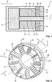
- Fig. 1 is shown in a sectional view along a machine axis 2, an electric machine 4, which is an axial flux motor, and which serves in the assembled state, the propulsion example of a motor vehicle.
- the electric machine 4 has a housing 6 within which a rotor 8 rotatably mounted about the machine axis 2 is positioned, which is connected to a shaft 10.
- the rotor 8 is designed substantially cylindrical and arranged concentrically to the machine axis 2 and the shaft 10.
- the bearing of the shaft 10 and the rotor 8 by means not shown in detail bearings, such as ball bearings.
- the shaft 10 is led out of the housing 6, for which this has a pin, not shown. At this are to be driven components of the motor vehicle, such as a wheel, connected or at least operatively connected.
- the electric machine 4 further has a stator 12 with a central opening 14, within which the shaft 10 is arranged, and which runs parallel to the machine axis 2.
- the stator 12 is designed substantially cylindrical or hollow cylindrical and arranged concentrically to the machine axis 2, wherein the rotor 8 is located on an end face of the stator 12. In this way, the electric machine 4 is comparatively compact, with a tilting of the rotor 8 is substantially excluded.
- the electric machine 4 has only a single rotor 8 in the variant shown here.
- a magnetic field is created during operation, which is configured at least in the region of the shaft 10 parallel to the machine axis 2, and interacts with permanent magnets, not shown, of the rotor 8.
- the stator 12 is energized by means of an inverter, not shown.
- the stator 12 has a support structure 16 and a number of inserts 18, which are connected to the support structure 16 and project through this in the axial direction 16 therethrough.
- cooling plate 24 Between the support structure 16 and the annular, perpendicular to the machine axis 2 arranged cooling plate 24 is a fixed to the support structure 16 and the cooling plate 24 integral flange 26, which is also configured with the exception of the recesses for the sections 20 annular.
- the flange 26 is made of an aluminum and a part of the one-piece housing. 6
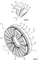
- Fig. 2 is perspective and in Fig. 3 shown in a plan view of the support structure 16, which is made of a sintered, powdery soft magnetic material composite containing, for example, iron powder.
- the support structure 16 is arranged concentrically to the machine axis 2, which is parallel to an axial direction A, and thus surrounds these in the radial direction R.
- radial direction R is meant in particular a direction which is perpendicular to the axial direction A and the machine axis 2 or directed away from this.
- the support structure 16 has an inner ring 28 which surrounds the central opening 14.
- the inner ring 28 itself has on its radial inner side a circular shaped surface, whereas the outer periphery of the cross section of the inner ring 28 is formed perpendicular to the machine axis 2 by means of a regular nine-corner.
- a web 30 is free end marc positioned, which extends in the radial direction R.
- Each of these webs 30 has as its respective tangential boundary, ie in a tangential direction T, a staircase or step shape.
- the radially outer end of each web 30 is connected to an outer ring 32 which surrounds the inner ring 28 in the radial direction R. Consequently, by means of the webs 30 and the inner and outer rings 28, 32 mounting openings 34 are formed, which are arranged rotationally symmetrical with respect to the machine axis 2, and each having a substantially trapezoidal cross-section.
- Each of the mounting openings 34 is further bounded by a jacket-segment-shaped cover 36 of the outer ring 32 in the radial direction R, which has an enlarged axial extent, ie an enlarged extent in a direction parallel to the machine axis 2 compared to the inner ring 14.
- the webs 30 have a corresponding extension to this.
- the cross section of each shell-segment-shaped cover 36 perpendicular to the machine axis 2 is crescent-shaped or circular segment-shaped.
- the support structure 16 is formed by means of similar, separate segments 38, one of which in Fig. 4 is shown in perspective.
- Each segment 38 has both a portion of the outer ring 32 with a respective one of the covers 36 and a portion of the inner ring 28 and a single of the webs 30. All segments 38 are integrally created in a sintering process and in the tangential direction T to create a Fig. 2 and 3 arranged carrier structure 16 and fixed to each other. Due to the use of the individual segments 38, the creation of an electric machine 4 with a comparatively large spatial extent is also possible, with only the spatial extent of the in Fig. 4 required segment 38 is needed.
- FIG. 5 one of the inserts 18 of the electric machine 4 is shown in perspective, wherein the number of inserts 18 of the electric machine 4 is equal to the number of mounting holes 34.
- Each insert 18 has a laminated core 40 with a number of individual sheets 42, which are punched from a soft iron sheet and stacked in the radial direction R.
- the sheets 42 have in the radial direction R a coating by means of which the adjacent sheets 42 are electrically isolated from each other.
- the laminated core 40 has five sheet metal stacks 44, wherein all the sheets 42 of each of the sheet metal stacks 44 have the same shape, and wherein the sheets 42 differ from different sheet stacks.
- Each of the sheet stacks 44 has the same number of sheets 42, wherein the individual sheets 42 of each stack of sheets 44 and the sheet stacks 44 are each connected to each other, for example by means of soldering, welding, gluing or Stamped packetization.
- All plates 42 are in this case configured substantially U-shaped, wherein the two parallel legs of the U-shape have a on the other leg facing the rear handle 46. As a result, each plate 42 has a substantially pentagonal recess. The recesses of all plates 42 are equal and aligned with each other.
- the laminated core 40 has a radially extending Statornut 48 into which a radially extending slot 50 opens, which is located between the two rear grips 46, and in the tangential direction T compared to the stator 48 has a reduced extent.
- the laminated core 40 is arranged axially symmetrical with respect to a straight line extending in the radial direction R, and with increasing distance from the machine axis 2, the surface of the plates 42 is increased, with all the plates 42 each of the same sheet stack 44 have the same shape and consequently the same area.
- the laminated core 40 in the tangential direction T as a limit to a step shape in the assembled state, as in Fig.
- the support structure 16 is toothed with the insert 18, which is essentially formed by means of the laminated core 40, and between the support structure 16 under the insert 18, a positive connection is created.
- the insert 18 rests both in sections on the inner ring 28 and on the outer ring 32, the jacket-segment-shaped cover 36 covering the insert 18 in the radial direction R.
- the insert 18 in the radial direction R is surrounded by the cover 36 and other components of the outer ring 32.
- the cover 36 is here recessed in the tangential direction T, so that it is aligned with the stator 48.
- Fig. 7 is the support structure with nine attached thereto 18 inserts according to Fig. 2 shown, wherein in each mounting hole 34 from the individual segments 38 created support structure 16 of the inserts 18 is positively positioned.
- Each of the nine similar inserts 18 abuts both the inner ring 28 and the outer ring 32 in sections. Consequently, each of the inserts 18 in the radial direction R is at least partially disposed between the inner ring 28 and the outer ring 32.
- inserts 18 do not have the protruding through the support structure 16 section 20.
- Each of the covers 36 is wrapped by a respective associated electrical winding 51, which are made of a copper enameled wire.
- Each of the electric windings 51 is guided by two stator slots 48 adjacent in the tangential direction T, so that the axis of each of the electrical windings 51 is parallel to and spaced from the rotation axis 2.
- a pole piece 52 of the electric machine is formed in each case with the halves of adjacent inserts 18 facing each other and the radial web 30 arranged therebetween, which consequently has nine pole shoes 52.
- Each of the pole pieces 52 is thus associated with one of the electrical windings 51.
- each of the pole pieces 52 is wound with the associated electrical windings 51.
- the covers 36 serve as a magnetic yoke and for positioning the electrical winding 51, wherein due to the radially outer circumferential surface of the covers 36, are avoided in the substantially sharp edges, damage to the electrical winding 51 during assembly is excluded.
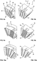
- Fig. 8 is according to Fig. 6 a modification of the support structure 16 and the insert 18 shown in Fig. 8 according to Fig. 5 is shown.
- the insert 18 has two groove-shaped recesses 54 extending parallel to the slot 50, the cover 36 having a notch 56 corresponding thereto, so that each of the recesses 52 is aligned with one of the notches 56 of the cover 36.
- the two recesses 54 are arranged axially symmetrically with respect to a straight line defined by means of the slot 50. Due to the recesses 54 a cogging torque between the rotor 8 and the stator 12 is reduced, so that during operation of the rotor has an improved concentricity.
- Figs. 6 a modification of the support structure 16 and the insert 18 shown in Fig. 8 according to Fig. 5 is shown.
- the insert 18 has two groove-shaped recesses 54 extending parallel to the slot 50, the cover 36 having a notch 56 corresponding thereto, so that each of the recesses 52
- FIG. 9A and 9B is a further embodiment of the insert 18 and the support structure 16, wherein the insert 18 has four radially extending recesses 54.
- Each of the covers 36 has aligned notches 56 in the assembled state with the recesses, and therefore each of the recesses 36 includes four such notches 56.
- the recesses 54 are arranged axially symmetrically with respect to the radially extending slot 50, wherein the cross section of each of the recesses 54 in the radial direction R substantially corresponds to the variant shown in the previous embodiment.
- Figs. 10A and 10B is a variation of the in 8A, 8B shown embodiment of the insert 18 and the support structure 16 shown.
- the recesses 54 are in turn formed by means of the individual sheet stacks 44, wherein the individual sections of the recesses 54, however, are not aligned. Consequently, the two recesses 54 are configured step-shaped, with increasing the radial distance from the machine axis 2, the distance of the radial recesses 54 to the slot 50 increases.
- each insert 18 has four of the radial recesses 54, which are each designed step-shaped.
- two of the groove-shaped radial recesses 54 are arranged on one of the sides of the slot 50 in the tangential direction T with respect to the slot 50.
- the distance between the recesses 54 and the radial slot 50 increases in the tangential direction T.
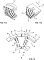
- Fig. 12 is seen in a plan view of the cooling plate 24 seen one of the inserts 18 having the portion 20.
- the insert 18 is arranged between two in the tangential direction T adjacent to each other arranged segments 38 of the support structure 16.
- the insert 18 is positively between two of the total of nine webs 30 of the support structure 16 and between the inner ring 28 and the outer ring 32 in one of the mounting holes 34.
- the insert 18 thus has a fir-tree shape in a cross section perpendicular to the machine axis 2 ,
- the insert 18 has the projecting through the support structure 16 section 20, which in tangential Direction T is tapered designed.
- the laminated core 40 on the end face 22 which has a reduced area compared to the mounting hole 34.
- the boundary of the section 20 in the tangential direction T is in turn created by means of a step or staircase shape.
- the section 20 is integrally formed with the respective, the other areas of the laminated core w40 forming plates 42.
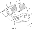
- Fig. 13 is shown in an elevational view of the mounted insert 18 which projects in the axial direction A through the support structure 16 therethrough.
- the end face 22 abuts the cooling plate 24 and is in thermal contact therewith.
- a heating of the laminated core 40 which takes place due to energization of the electrical winding 51, derived by means of the cooling plate 24, which is why the insert 18 during operation has a substantially constant temperature.
- the cooling plate 24 not shown on cooling fins or lines for a cooling liquid.
- the area between the support structure 16 and the cooling plate 24 is filled by means of the flange 26, which is integral with other components of the housing 6. On the flange 26 and other components, not shown, of the housing 6, the support structure 16 and the cooling plate 24 are attached.
- the flange 26 engages in the axial direction A extending bores 58, which are introduced into the outer ring 32, and in Fig. 12 are shown.
- the flange 26 is positively against the portion 20 of the insert 18. Due to the reduced expansion in the tangential direction T of the insert 18 in the region of the section 20, the flange 26 in this region is thickened in comparison to the webs 30 of the support structure 16 extending in the radial direction R, which therefore has a comparatively high structural integrity.
- the support structure 16 is stabilized by means of the flange 26 and a movement of the individual segments 38 of the support structure 16 is prevented.
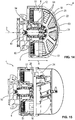
- Fig. 14 is the axial flux motor 4 in a sectional view without cooling plate 24 and in Fig. 15 shown with attached cooling plate 24.
- the flange 26 is configured star-shaped and integral with other components of the cup-shaped housing 6. In the assembled state, the flange 26, as in Fig. 15 shown in the Essentially completely covered by the cooling plate 24 which is connected to the housing 6 in the axial direction A.
- the flange 26 has centrally a cup-shaped recess 60, to which a mounting structure 62 extending parallel to the axis of rotation 2 is connected in the form of a hollow cylinder, which is directed away from the cooling plate 24.
- the mounting structure 62 surrounds in the radial direction R three angular contact ball bearings 64.
- angular contact ball bearings 64 in an axial flow motor 4 which have a pressure angle with respect to the axis of rotation 2, which is always inclined in the same direction, ie by means of which purely mechanical no bias in the axial direction A is created, is independent of the other, concrete embodiment the stator 12, in particular the inserts 18 and / or the support structure 16, which may be missing here.
- This use and such Axialmannmotor 4 are currently considered rather as an independent invention.
- the rotor 8 also has a laminated core, are attached to the permanent magnet, not shown. These are substantially segment-shaped and cooperate with the trapezoidal electrical windings 51, two of which are shown in the figures, the upper being shown in a sectional view and the lower in a side view.
Landscapes
- Engineering & Computer Science (AREA)
- Power Engineering (AREA)
- Iron Core Of Rotating Electric Machines (AREA)
Applications Claiming Priority (1)
| Application Number | Priority Date | Filing Date | Title |
|---|---|---|---|
| DE102015223766.4A DE102015223766A1 (de) | 2015-11-30 | 2015-11-30 | Elektrische Maschine |
Publications (2)
| Publication Number | Publication Date |
|---|---|
| EP3174183A1 true EP3174183A1 (fr) | 2017-05-31 |
| EP3174183B1 EP3174183B1 (fr) | 2019-09-18 |
Family
ID=57189939
Family Applications (1)
| Application Number | Title | Priority Date | Filing Date |
|---|---|---|---|
| EP16195302.1A Active EP3174183B1 (fr) | 2015-11-30 | 2016-10-24 | Machine électrique |
Country Status (4)
| Country | Link |
|---|---|
| US (1) | US10291086B2 (fr) |
| EP (1) | EP3174183B1 (fr) |
| CN (1) | CN106816970B (fr) |
| DE (1) | DE102015223766A1 (fr) |
Cited By (3)
| Publication number | Priority date | Publication date | Assignee | Title |
|---|---|---|---|---|
| EP3702739A1 (fr) * | 2019-03-01 | 2020-09-02 | Baumer Hübner GmbH | Flasque de palier et dispositif de mesure de position à stabilité thermique de position |
| US20210344238A1 (en) * | 2018-12-05 | 2021-11-04 | Sumitomo Electric Industries, Ltd. | Core, stator, and rotary electric machine |
| WO2025087480A1 (fr) | 2023-10-27 | 2025-05-01 | Schaeffler Technologies AG & Co. KG | Procédé de fabrication d'un élément d'un composant générateur d'énergie d'une machine tournante électrique, et composant générateur d'énergie d'une machine tournante électrique |
Families Citing this family (39)
| Publication number | Priority date | Publication date | Assignee | Title |
|---|---|---|---|---|
| EP3485558B1 (fr) * | 2016-07-18 | 2019-12-18 | Universiteit Gent | Stator pour une machine à flux axial et son procédé de production |
| US11177726B2 (en) | 2017-01-11 | 2021-11-16 | Infinitum Electric, Inc. | System and apparatus for axial field rotary energy device |
| US10186922B2 (en) | 2017-01-11 | 2019-01-22 | Infinitum Electric Inc. | System and apparatus for axial field rotary energy device |
| US10141804B2 (en) | 2017-01-11 | 2018-11-27 | Infinitum Electric Inc. | System, method and apparatus for modular axial field rotary energy device |
| US20180205301A1 (en) * | 2017-01-17 | 2018-07-19 | Ronald J. Didier | Stacked transflux electric motor |
| WO2019190959A1 (fr) | 2018-03-26 | 2019-10-03 | Infinitum Electric Inc. | Système et appareil pour dispositif d'énergie rotatif à champ axial |
| KR20240122577A (ko) | 2018-07-10 | 2024-08-12 | 인피니텀 일렉트로닉, 아이앤씨. | 축방향 필드 회전 에너지 장치용 시스템 및 장치 |
| CN209016823U (zh) * | 2018-11-02 | 2019-06-21 | 上海磁雷革传动系统有限公司 | 一种线圈连接件及线圈组件 |
| EP3745559B1 (fr) * | 2019-05-27 | 2022-03-09 | Magnax Bv | Stator pour une machine à flux axial |
| AU2020357566B2 (en) * | 2019-10-03 | 2023-04-27 | Parker-Hannifin Corporation | Electric motor with enhanced thermal characteristics |
| DE102019216861A1 (de) * | 2019-10-31 | 2021-05-06 | Robert Bosch Gmbh | Axialflussmaschine für ein elektrisches Bearbeitungsgerät sowie elektrisches Bearbeitungsgerät mit einer Axialflussmaschine |
| DE102019216858A1 (de) | 2019-10-31 | 2021-05-06 | Robert Bosch Gmbh | Axialflussmaschine für ein elektrisches Bearbeitungsgerät sowie elektrisches Bearbeitungsgerät mit einer Axialflussmaschine |
| DE102019216844A1 (de) | 2019-10-31 | 2021-05-06 | Robert Bosch Gmbh | Axialflussmaschine für ein elektrisches Bearbeitungsgerät sowie elektrisches Bearbeitungsgerät mit einer Axialflussmaschine |
| DE102019216860A1 (de) | 2019-10-31 | 2021-05-06 | Robert Bosch Gmbh | Axialflussmaschine für ein elektrisches Bearbeitungsgerät sowie elektrisches Bearbeitungsgerät mit einer Axialflussmaschine |
| DE102019216847A1 (de) | 2019-10-31 | 2021-05-06 | Robert Bosch Gmbh | Axialflussmaschine für ein elektrisches Bearbeitungsgerät sowie elektrisches Bearbeitungsgerät mit einer Axialflussmaschine |
| DE102019216853A1 (de) | 2019-10-31 | 2021-05-06 | Robert Bosch Gmbh | Axialflussmaschine für ein elektrisches Bearbeitungsgerät sowie elektrisches Bearbeitungsgerät mit einer Axialflussmaschine |
| US11283319B2 (en) | 2019-11-11 | 2022-03-22 | Infinitum Electric, Inc. | Axial field rotary energy device with PCB stator having interleaved PCBS |
| CN112803691B (zh) | 2019-11-13 | 2025-06-03 | 通用汽车环球科技运作有限责任公司 | 带分布式绕组的轴向磁通马达 |
| CN112821702B (zh) | 2019-11-15 | 2025-02-25 | 通用汽车环球科技运作有限责任公司 | 用于轴向磁通马达的混合定子芯部件设计 |
| US20210218304A1 (en) | 2020-01-14 | 2021-07-15 | Infinitum Electric, Inc. | Axial field rotary energy device having pcb stator and variable frequency drive |
| EP3852244A1 (fr) * | 2020-01-20 | 2021-07-21 | Hamilton Sundstrand Corporation | Machines électriques |
| DE102020113047A1 (de) | 2020-05-14 | 2021-11-18 | Schaeffler Technologies AG & Co. KG | Elektromotorbauteil und Verfahren zur Herstellung eines Elektromotorbauteils eines Axialflussmotors |
| DE102020114441A1 (de) | 2020-05-29 | 2021-12-02 | Schaeffler Technologies AG & Co. KG | Stator für eine elektrische Axialflussmaschine und elektrische Axialflussmaschine |
| CN112134381B (zh) * | 2020-08-19 | 2023-03-24 | 沈阳工业大学 | 一种轴向磁通永磁电机用内置磁钢复合极转子 |
| CN114552815B (zh) | 2020-11-26 | 2025-05-02 | 通用汽车环球科技运作有限责任公司 | 轴向磁通电机定子的直接接触冷却 |
| FR3118346B1 (fr) * | 2020-12-17 | 2023-10-20 | Renault Sas | Elément à pôles magnétiques pour rotor de machine électrique à flux axial |
| US11482908B1 (en) | 2021-04-12 | 2022-10-25 | Infinitum Electric, Inc. | System, method and apparatus for direct liquid-cooled axial flux electric machine with PCB stator |
| US11646611B2 (en) | 2021-07-28 | 2023-05-09 | GM Global Technology Operations LLC | Locking mechanism for segmented stator core |
| US11689073B2 (en) | 2021-08-13 | 2023-06-27 | GM Global Technology Operations LLC | Rotor core design |
| US20230047862A1 (en) * | 2021-08-13 | 2023-02-16 | GM Global Technology Operations LLC | Segmented stator core design |
| CN114421660A (zh) * | 2022-01-21 | 2022-04-29 | 上海盘毂动力科技股份有限公司 | 轴向磁场电机的定子铁芯固定结构 |
| CN116780795A (zh) * | 2022-03-10 | 2023-09-19 | 通用汽车环球科技运作有限责任公司 | 包括具有软磁复合材料部分和层压层的绝缘混合定子芯的轴向磁通电机 |
| DE102022106345A1 (de) | 2022-03-18 | 2023-09-21 | Schaeffler Technologies AG & Co. KG | Stator einer elektrischen Rotationsmaschine, elektrische Rotationsmaschine und Getriebemotoreinheit |
| CN117240033A (zh) * | 2022-06-07 | 2023-12-15 | 通用汽车环球科技运作有限责任公司 | 带有集成功率电子器件和双侧冷却的轴向通量马达组件 |
| US12160139B2 (en) | 2022-06-09 | 2024-12-03 | Regal Beloit Australia Pty Ltd | Variable torque constant electric machines having a radial spoked rotor with axial flux magnet plates and methods thereof |
| US12206289B2 (en) | 2022-08-26 | 2025-01-21 | Regal Beloit America, Inc. | Radial spoked rotor with axial assist magnets |
| FR3144438A1 (fr) * | 2022-12-22 | 2024-06-28 | Valeo Equipements Electriques Moteur | Stator de machine électrique à flux axial |
| DE102023119367A1 (de) * | 2023-07-21 | 2025-01-23 | Bayerische Motoren Werke Aktiengesellschaft | Elektrische Maschine zum Antreiben eines Kraftfahrzeugs und Kraftfahrzeug mit einer als elektrischen Maschine |
| CN119171658B (zh) * | 2024-08-28 | 2026-03-31 | 东风汽车集团股份有限公司 | 定子结构、定子结构的制造方法和电机 |
Citations (4)
| Publication number | Priority date | Publication date | Assignee | Title |
|---|---|---|---|---|
| FR2851088A1 (fr) * | 2003-02-12 | 2004-08-13 | Seb Sa | Stator pour moteur electrique a flux axial |
| US20110316381A1 (en) * | 2009-02-26 | 2011-12-29 | Yoshinari Asano | Armature core |
| US20120126653A1 (en) * | 2010-11-23 | 2012-05-24 | Industrial Technology Research Institute | Axial-flux thin-plate motor |
| US20130140920A1 (en) * | 2011-12-02 | 2013-06-06 | Industrial Technology Research Institute | Stator assembly structure for axial flux electric machine |
Family Cites Families (16)
| Publication number | Priority date | Publication date | Assignee | Title |
|---|---|---|---|---|
| US4547714A (en) * | 1978-08-11 | 1985-10-15 | Papst-Motoren Gmbh & Co. Kg | Low magnetic leakage flux brushless pulse controlled d-c motor |
| DE3423777A1 (de) * | 1984-06-28 | 1986-01-02 | Philips Patentverwaltung Gmbh, 2000 Hamburg | Zweipoliger einphasensynchronmotor mit permanentmagnetischem rotor (modulmotor) |
| DE19711750A1 (de) * | 1997-03-21 | 1998-10-08 | Daimler Benz Ag | Klauenpolmaschine |
| TW553555U (en) * | 2001-09-26 | 2003-09-11 | Jia-Hau Fan | Modular stator structure |
| JP2004364444A (ja) * | 2003-06-06 | 2004-12-24 | Matsushita Electric Ind Co Ltd | 密閉型電動圧縮機 |
| DE102006022836A1 (de) * | 2006-05-16 | 2007-11-22 | Minebea Co., Ltd. | Statoranordnung und Rotoranordnung für eine Transversalflußmaschine |
| JP2009239986A (ja) * | 2008-03-25 | 2009-10-15 | Tdk Corp | コイルボビン及びそれを用いた回転機 |
| JP2009240127A (ja) * | 2008-03-28 | 2009-10-15 | Tdk Corp | アキシャル型回転機 |
| JP5256007B2 (ja) * | 2008-12-02 | 2013-08-07 | アスモ株式会社 | 電機子並びにアキシャルギャップ型回転電機 |
| DE102010036828A1 (de) * | 2010-08-04 | 2012-02-09 | Friedrich Waltermann | Stator für elektrische Maschine mit überlappenden U-förmigen Kernblechen |
| DE102010064173A1 (de) * | 2010-12-27 | 2012-06-28 | Robert Bosch Gmbh | Wicklungszahn für eine elektrische Maschine, Maschinenkomponente und elektrische Maschine |
| DE102012206338B4 (de) * | 2012-04-18 | 2021-06-02 | Schaeffler Technologies AG & Co. KG | Nockenwellenversteller mit Stator-Deckel-Einheit zur automatischen Einstellung eines Verriegelungsspiels |
| US10170959B2 (en) * | 2013-03-13 | 2019-01-01 | Regal Beloit America, Inc. | Electrical machines and methods of assembling the same |
| EP2787610B1 (fr) * | 2013-04-05 | 2015-07-22 | F. Boccadoro SA | Procédé et dispositif de fabrication de stators et de rotors pour des moteurs axiaux |
| KR20150019028A (ko) * | 2013-08-12 | 2015-02-25 | 현대모비스 주식회사 | 축방향자속모터의 고정자코어 및 이의 제작방법 |
| US20160072362A1 (en) * | 2014-09-05 | 2016-03-10 | Steve Michael Kube | Hybrid Axial Flux Machines and Mechanisms |
-
2015
- 2015-11-30 DE DE102015223766.4A patent/DE102015223766A1/de not_active Withdrawn
-
2016
- 2016-10-24 EP EP16195302.1A patent/EP3174183B1/fr active Active
- 2016-11-30 US US15/364,958 patent/US10291086B2/en not_active Expired - Fee Related
- 2016-11-30 CN CN201611080322.7A patent/CN106816970B/zh active Active
Patent Citations (4)
| Publication number | Priority date | Publication date | Assignee | Title |
|---|---|---|---|---|
| FR2851088A1 (fr) * | 2003-02-12 | 2004-08-13 | Seb Sa | Stator pour moteur electrique a flux axial |
| US20110316381A1 (en) * | 2009-02-26 | 2011-12-29 | Yoshinari Asano | Armature core |
| US20120126653A1 (en) * | 2010-11-23 | 2012-05-24 | Industrial Technology Research Institute | Axial-flux thin-plate motor |
| US20130140920A1 (en) * | 2011-12-02 | 2013-06-06 | Industrial Technology Research Institute | Stator assembly structure for axial flux electric machine |
Cited By (4)
| Publication number | Priority date | Publication date | Assignee | Title |
|---|---|---|---|---|
| US20210344238A1 (en) * | 2018-12-05 | 2021-11-04 | Sumitomo Electric Industries, Ltd. | Core, stator, and rotary electric machine |
| US11888347B2 (en) * | 2018-12-05 | 2024-01-30 | Sumitomo Electric Industries, Ltd. | Core, stator, and rotary electric machine |
| EP3702739A1 (fr) * | 2019-03-01 | 2020-09-02 | Baumer Hübner GmbH | Flasque de palier et dispositif de mesure de position à stabilité thermique de position |
| WO2025087480A1 (fr) | 2023-10-27 | 2025-05-01 | Schaeffler Technologies AG & Co. KG | Procédé de fabrication d'un élément d'un composant générateur d'énergie d'une machine tournante électrique, et composant générateur d'énergie d'une machine tournante électrique |
Also Published As
| Publication number | Publication date |
|---|---|
| US20170155291A1 (en) | 2017-06-01 |
| CN106816970A (zh) | 2017-06-09 |
| EP3174183B1 (fr) | 2019-09-18 |
| US10291086B2 (en) | 2019-05-14 |
| DE102015223766A1 (de) | 2017-06-01 |
| CN106816970B (zh) | 2020-07-28 |
Similar Documents
| Publication | Publication Date | Title |
|---|---|---|
| EP3174183B1 (fr) | Machine électrique | |
| DE102011121793B4 (de) | Elektromotor | |
| EP1114500B1 (fr) | Moteur electrique | |
| WO2021003510A2 (fr) | Stator pour une machine à flux axial | |
| EP2619883B1 (fr) | Élément pour une machine électrique | |
| EP4070436B1 (fr) | Machine à flux axial comprenant un stator ayant des segments de tôle s'étendant radialement | |
| WO2023110769A1 (fr) | Rotor pour une machine électrique comprenant un canal de refroidissement dans un séparateur de pôles | |
| EP3309934A1 (fr) | Machine électrique | |
| DE102016116386A1 (de) | Einphasiger Permanentmagnetmotor | |
| WO2021003509A1 (fr) | Stator conçu pour une machine à flux axial | |
| EP1018206A1 (fr) | Module stator pour un moteur electrique | |
| DE102022004793A1 (de) | Befestigungsanordnung eines Blechpakets eines Stators an einem Gehäuse einer Axialflussmaschine, insbesondere für ein Kraftfahrzeug, Axialflussmaschine sowie Kraftfahrzeug | |
| DE102009004474B4 (de) | Transversalflussmaschine mit scheibenförmigen Rotoren | |
| EP2992589A2 (fr) | Rotor pour un moteur a reluctance et son procede de fabrication | |
| EP2374198B1 (fr) | Machine électrique avec rotor à pôles à griffes | |
| DE102019130358A1 (de) | Rotor für eine elektrische Maschine und elektrische Maschine | |
| DE102014011585A1 (de) | Elektrische Maschine | |
| EP2067237B1 (fr) | Machine synchrone | |
| EP4179608A1 (fr) | Segment de noyau stratifié et son procédé de production | |
| DE19743549C2 (de) | Verfahren zur Herstellung einer lamellierten elektrischen Maschine | |
| EP3472922B1 (fr) | Rotor pour une machine asynchrone électrique à cage d'écureuil surmoulée, machine électrique et procédé de fabrication | |
| EP3667871A1 (fr) | Machine électrique | |
| DE102024208426B3 (de) | Rotor eines Elektromotors | |
| EP3496236A1 (fr) | Rotor d'une machine électrique | |
| DE102023210808A1 (de) | Stator mit geschrägten Einzelzahnsegmenten sowie elektrische Maschine mit dem Stator |
Legal Events
| Date | Code | Title | Description |
|---|---|---|---|
| PUAI | Public reference made under article 153(3) epc to a published international application that has entered the european phase |
Free format text: ORIGINAL CODE: 0009012 |
|
| STAA | Information on the status of an ep patent application or granted ep patent |
Free format text: STATUS: THE APPLICATION HAS BEEN PUBLISHED |
|
| AK | Designated contracting states |
Kind code of ref document: A1 Designated state(s): AL AT BE BG CH CY CZ DE DK EE ES FI FR GB GR HR HU IE IS IT LI LT LU LV MC MK MT NL NO PL PT RO RS SE SI SK SM TR |
|
| AX | Request for extension of the european patent |
Extension state: BA ME |
|
| STAA | Information on the status of an ep patent application or granted ep patent |
Free format text: STATUS: REQUEST FOR EXAMINATION WAS MADE |
|
| 17P | Request for examination filed |
Effective date: 20171120 |
|
| RBV | Designated contracting states (corrected) |
Designated state(s): AL AT BE BG CH CY CZ DE DK EE ES FI FR GB GR HR HU IE IS IT LI LT LU LV MC MK MT NL NO PL PT RO RS SE SI SK SM TR |
|
| GRAP | Despatch of communication of intention to grant a patent |
Free format text: ORIGINAL CODE: EPIDOSNIGR1 |
|
| STAA | Information on the status of an ep patent application or granted ep patent |
Free format text: STATUS: GRANT OF PATENT IS INTENDED |
|
| INTG | Intention to grant announced |
Effective date: 20190618 |
|
| GRAS | Grant fee paid |
Free format text: ORIGINAL CODE: EPIDOSNIGR3 |
|
| GRAA | (expected) grant |
Free format text: ORIGINAL CODE: 0009210 |
|
| STAA | Information on the status of an ep patent application or granted ep patent |
Free format text: STATUS: THE PATENT HAS BEEN GRANTED |
|
| AK | Designated contracting states |
Kind code of ref document: B1 Designated state(s): AL AT BE BG CH CY CZ DE DK EE ES FI FR GB GR HR HU IE IS IT LI LT LU LV MC MK MT NL NO PL PT RO RS SE SI SK SM TR |
|
| REG | Reference to a national code |
Ref country code: GB Ref legal event code: FG4D Free format text: NOT ENGLISH |
|
| REG | Reference to a national code |
Ref country code: CH Ref legal event code: EP Ref country code: CH Ref legal event code: NV Representative=s name: E. BLUM AND CO. AG PATENT- UND MARKENANWAELTE , CH |
|
| REG | Reference to a national code |
Ref country code: DE Ref legal event code: R096 Ref document number: 502016006660 Country of ref document: DE |
|
| REG | Reference to a national code |
Ref country code: AT Ref legal event code: REF Ref document number: 1182484 Country of ref document: AT Kind code of ref document: T Effective date: 20191015 |
|
| REG | Reference to a national code |
Ref country code: IE Ref legal event code: FG4D Free format text: LANGUAGE OF EP DOCUMENT: GERMAN |
|
| REG | Reference to a national code |
Ref country code: NL Ref legal event code: MP Effective date: 20190918 |
|
| PG25 | Lapsed in a contracting state [announced via postgrant information from national office to epo] |
Ref country code: HR Free format text: LAPSE BECAUSE OF FAILURE TO SUBMIT A TRANSLATION OF THE DESCRIPTION OR TO PAY THE FEE WITHIN THE PRESCRIBED TIME-LIMIT Effective date: 20190918 Ref country code: BG Free format text: LAPSE BECAUSE OF FAILURE TO SUBMIT A TRANSLATION OF THE DESCRIPTION OR TO PAY THE FEE WITHIN THE PRESCRIBED TIME-LIMIT Effective date: 20191218 Ref country code: SE Free format text: LAPSE BECAUSE OF FAILURE TO SUBMIT A TRANSLATION OF THE DESCRIPTION OR TO PAY THE FEE WITHIN THE PRESCRIBED TIME-LIMIT Effective date: 20190918 Ref country code: LT Free format text: LAPSE BECAUSE OF FAILURE TO SUBMIT A TRANSLATION OF THE DESCRIPTION OR TO PAY THE FEE WITHIN THE PRESCRIBED TIME-LIMIT Effective date: 20190918 Ref country code: FI Free format text: LAPSE BECAUSE OF FAILURE TO SUBMIT A TRANSLATION OF THE DESCRIPTION OR TO PAY THE FEE WITHIN THE PRESCRIBED TIME-LIMIT Effective date: 20190918 Ref country code: NO Free format text: LAPSE BECAUSE OF FAILURE TO SUBMIT A TRANSLATION OF THE DESCRIPTION OR TO PAY THE FEE WITHIN THE PRESCRIBED TIME-LIMIT Effective date: 20191218 |
|
| REG | Reference to a national code |
Ref country code: LT Ref legal event code: MG4D |
|
| PG25 | Lapsed in a contracting state [announced via postgrant information from national office to epo] |
Ref country code: LV Free format text: LAPSE BECAUSE OF FAILURE TO SUBMIT A TRANSLATION OF THE DESCRIPTION OR TO PAY THE FEE WITHIN THE PRESCRIBED TIME-LIMIT Effective date: 20190918 Ref country code: RS Free format text: LAPSE BECAUSE OF FAILURE TO SUBMIT A TRANSLATION OF THE DESCRIPTION OR TO PAY THE FEE WITHIN THE PRESCRIBED TIME-LIMIT Effective date: 20190918 Ref country code: GR Free format text: LAPSE BECAUSE OF FAILURE TO SUBMIT A TRANSLATION OF THE DESCRIPTION OR TO PAY THE FEE WITHIN THE PRESCRIBED TIME-LIMIT Effective date: 20191219 Ref country code: AL Free format text: LAPSE BECAUSE OF FAILURE TO SUBMIT A TRANSLATION OF THE DESCRIPTION OR TO PAY THE FEE WITHIN THE PRESCRIBED TIME-LIMIT Effective date: 20190918 |
|
| PG25 | Lapsed in a contracting state [announced via postgrant information from national office to epo] |
Ref country code: NL Free format text: LAPSE BECAUSE OF FAILURE TO SUBMIT A TRANSLATION OF THE DESCRIPTION OR TO PAY THE FEE WITHIN THE PRESCRIBED TIME-LIMIT Effective date: 20190918 Ref country code: ES Free format text: LAPSE BECAUSE OF FAILURE TO SUBMIT A TRANSLATION OF THE DESCRIPTION OR TO PAY THE FEE WITHIN THE PRESCRIBED TIME-LIMIT Effective date: 20190918 Ref country code: PT Free format text: LAPSE BECAUSE OF FAILURE TO SUBMIT A TRANSLATION OF THE DESCRIPTION OR TO PAY THE FEE WITHIN THE PRESCRIBED TIME-LIMIT Effective date: 20200120 Ref country code: EE Free format text: LAPSE BECAUSE OF FAILURE TO SUBMIT A TRANSLATION OF THE DESCRIPTION OR TO PAY THE FEE WITHIN THE PRESCRIBED TIME-LIMIT Effective date: 20190918 Ref country code: RO Free format text: LAPSE BECAUSE OF FAILURE TO SUBMIT A TRANSLATION OF THE DESCRIPTION OR TO PAY THE FEE WITHIN THE PRESCRIBED TIME-LIMIT Effective date: 20190918 Ref country code: IT Free format text: LAPSE BECAUSE OF FAILURE TO SUBMIT A TRANSLATION OF THE DESCRIPTION OR TO PAY THE FEE WITHIN THE PRESCRIBED TIME-LIMIT Effective date: 20190918 Ref country code: PL Free format text: LAPSE BECAUSE OF FAILURE TO SUBMIT A TRANSLATION OF THE DESCRIPTION OR TO PAY THE FEE WITHIN THE PRESCRIBED TIME-LIMIT Effective date: 20190918 |
|
| PG25 | Lapsed in a contracting state [announced via postgrant information from national office to epo] |
Ref country code: SM Free format text: LAPSE BECAUSE OF FAILURE TO SUBMIT A TRANSLATION OF THE DESCRIPTION OR TO PAY THE FEE WITHIN THE PRESCRIBED TIME-LIMIT Effective date: 20190918 Ref country code: IS Free format text: LAPSE BECAUSE OF FAILURE TO SUBMIT A TRANSLATION OF THE DESCRIPTION OR TO PAY THE FEE WITHIN THE PRESCRIBED TIME-LIMIT Effective date: 20200224 Ref country code: SK Free format text: LAPSE BECAUSE OF FAILURE TO SUBMIT A TRANSLATION OF THE DESCRIPTION OR TO PAY THE FEE WITHIN THE PRESCRIBED TIME-LIMIT Effective date: 20190918 Ref country code: CZ Free format text: LAPSE BECAUSE OF FAILURE TO SUBMIT A TRANSLATION OF THE DESCRIPTION OR TO PAY THE FEE WITHIN THE PRESCRIBED TIME-LIMIT Effective date: 20190918 |
|
| REG | Reference to a national code |
Ref country code: DE Ref legal event code: R097 Ref document number: 502016006660 Country of ref document: DE |
|
| PLBE | No opposition filed within time limit |
Free format text: ORIGINAL CODE: 0009261 |
|
| STAA | Information on the status of an ep patent application or granted ep patent |
Free format text: STATUS: NO OPPOSITION FILED WITHIN TIME LIMIT |
|
| PG2D | Information on lapse in contracting state deleted |
Ref country code: IS |
|
| PG25 | Lapsed in a contracting state [announced via postgrant information from national office to epo] |
Ref country code: LU Free format text: LAPSE BECAUSE OF NON-PAYMENT OF DUE FEES Effective date: 20191024 Ref country code: DK Free format text: LAPSE BECAUSE OF FAILURE TO SUBMIT A TRANSLATION OF THE DESCRIPTION OR TO PAY THE FEE WITHIN THE PRESCRIBED TIME-LIMIT Effective date: 20190918 Ref country code: IS Free format text: LAPSE BECAUSE OF FAILURE TO SUBMIT A TRANSLATION OF THE DESCRIPTION OR TO PAY THE FEE WITHIN THE PRESCRIBED TIME-LIMIT Effective date: 20200119 |
|
| REG | Reference to a national code |
Ref country code: BE Ref legal event code: MM Effective date: 20191031 |
|
| 26N | No opposition filed |
Effective date: 20200619 |
|
| PG25 | Lapsed in a contracting state [announced via postgrant information from national office to epo] |
Ref country code: SI Free format text: LAPSE BECAUSE OF FAILURE TO SUBMIT A TRANSLATION OF THE DESCRIPTION OR TO PAY THE FEE WITHIN THE PRESCRIBED TIME-LIMIT Effective date: 20190918 Ref country code: BE Free format text: LAPSE BECAUSE OF NON-PAYMENT OF DUE FEES Effective date: 20191031 Ref country code: MC Free format text: LAPSE BECAUSE OF FAILURE TO SUBMIT A TRANSLATION OF THE DESCRIPTION OR TO PAY THE FEE WITHIN THE PRESCRIBED TIME-LIMIT Effective date: 20190918 |
|
| PG25 | Lapsed in a contracting state [announced via postgrant information from national office to epo] |
Ref country code: IE Free format text: LAPSE BECAUSE OF NON-PAYMENT OF DUE FEES Effective date: 20191024 Ref country code: FR Free format text: LAPSE BECAUSE OF NON-PAYMENT OF DUE FEES Effective date: 20191118 |
|
| PG25 | Lapsed in a contracting state [announced via postgrant information from national office to epo] |
Ref country code: CY Free format text: LAPSE BECAUSE OF FAILURE TO SUBMIT A TRANSLATION OF THE DESCRIPTION OR TO PAY THE FEE WITHIN THE PRESCRIBED TIME-LIMIT Effective date: 20190918 |
|
| GBPC | Gb: european patent ceased through non-payment of renewal fee |
Effective date: 20201024 |
|
| PG25 | Lapsed in a contracting state [announced via postgrant information from national office to epo] |
Ref country code: MT Free format text: LAPSE BECAUSE OF FAILURE TO SUBMIT A TRANSLATION OF THE DESCRIPTION OR TO PAY THE FEE WITHIN THE PRESCRIBED TIME-LIMIT Effective date: 20190918 Ref country code: HU Free format text: LAPSE BECAUSE OF FAILURE TO SUBMIT A TRANSLATION OF THE DESCRIPTION OR TO PAY THE FEE WITHIN THE PRESCRIBED TIME-LIMIT; INVALID AB INITIO Effective date: 20161024 |
|
| PG25 | Lapsed in a contracting state [announced via postgrant information from national office to epo] |
Ref country code: GB Free format text: LAPSE BECAUSE OF NON-PAYMENT OF DUE FEES Effective date: 20201024 |
|
| PG25 | Lapsed in a contracting state [announced via postgrant information from national office to epo] |
Ref country code: TR Free format text: LAPSE BECAUSE OF FAILURE TO SUBMIT A TRANSLATION OF THE DESCRIPTION OR TO PAY THE FEE WITHIN THE PRESCRIBED TIME-LIMIT Effective date: 20190918 |
|
| PG25 | Lapsed in a contracting state [announced via postgrant information from national office to epo] |
Ref country code: MK Free format text: LAPSE BECAUSE OF FAILURE TO SUBMIT A TRANSLATION OF THE DESCRIPTION OR TO PAY THE FEE WITHIN THE PRESCRIBED TIME-LIMIT Effective date: 20190918 |
|
| PGFP | Annual fee paid to national office [announced via postgrant information from national office to epo] |
Ref country code: DE Payment date: 20241022 Year of fee payment: 9 |
|
| PGFP | Annual fee paid to national office [announced via postgrant information from national office to epo] |
Ref country code: AT Payment date: 20241021 Year of fee payment: 9 |
|
| PGFP | Annual fee paid to national office [announced via postgrant information from national office to epo] |
Ref country code: CH Payment date: 20241101 Year of fee payment: 9 |