EP3309934A1 - Machine électrique - Google Patents
Machine électrique Download PDFInfo
- Publication number
- EP3309934A1 EP3309934A1 EP17188143.6A EP17188143A EP3309934A1 EP 3309934 A1 EP3309934 A1 EP 3309934A1 EP 17188143 A EP17188143 A EP 17188143A EP 3309934 A1 EP3309934 A1 EP 3309934A1
- Authority
- EP
- European Patent Office
- Prior art keywords
- laminated core
- groove
- sheets
- slot closure
- electric machine
- Prior art date
- Legal status (The legal status is an assumption and is not a legal conclusion. Google has not performed a legal analysis and makes no representation as to the accuracy of the status listed.)
- Withdrawn
Links
- 238000010292 electrical insulation Methods 0.000 claims description 18
- 229910052751 metal Inorganic materials 0.000 description 18
- 239000002184 metal Substances 0.000 description 18
- 230000005291 magnetic effect Effects 0.000 description 12
- 238000004519 manufacturing process Methods 0.000 description 12
- RYGMFSIKBFXOCR-UHFFFAOYSA-N Copper Chemical compound [Cu] RYGMFSIKBFXOCR-UHFFFAOYSA-N 0.000 description 4
- 238000003860 storage Methods 0.000 description 4
- 229910052782 aluminium Inorganic materials 0.000 description 3
- XAGFODPZIPBFFR-UHFFFAOYSA-N aluminium Chemical compound [Al] XAGFODPZIPBFFR-UHFFFAOYSA-N 0.000 description 3
- 229910052802 copper Inorganic materials 0.000 description 3
- 239000010949 copper Substances 0.000 description 3
- 239000003302 ferromagnetic material Substances 0.000 description 3
- 238000001746 injection moulding Methods 0.000 description 3
- 239000004922 lacquer Substances 0.000 description 3
- 239000000463 material Substances 0.000 description 3
- 229910000976 Electrical steel Inorganic materials 0.000 description 2
- XEEYBQQBJWHFJM-UHFFFAOYSA-N Iron Chemical compound [Fe] XEEYBQQBJWHFJM-UHFFFAOYSA-N 0.000 description 2
- 238000004026 adhesive bonding Methods 0.000 description 2
- 238000003475 lamination Methods 0.000 description 2
- 238000004806 packaging method and process Methods 0.000 description 2
- 239000003973 paint Substances 0.000 description 2
- 229910000838 Al alloy Inorganic materials 0.000 description 1
- 229910000881 Cu alloy Inorganic materials 0.000 description 1
- 229910000831 Steel Inorganic materials 0.000 description 1
- 238000001816 cooling Methods 0.000 description 1
- 230000007797 corrosion Effects 0.000 description 1
- 238000005260 corrosion Methods 0.000 description 1
- 230000001419 dependent effect Effects 0.000 description 1
- 238000011161 development Methods 0.000 description 1
- 230000018109 developmental process Effects 0.000 description 1
- 230000001939 inductive effect Effects 0.000 description 1
- 229910052742 iron Inorganic materials 0.000 description 1
- 239000000203 mixture Substances 0.000 description 1
- 230000003071 parasitic effect Effects 0.000 description 1
- 239000002994 raw material Substances 0.000 description 1
- 239000010959 steel Substances 0.000 description 1
- 238000004804 winding Methods 0.000 description 1
Images

Classifications
-
- H—ELECTRICITY
- H02—GENERATION; CONVERSION OR DISTRIBUTION OF ELECTRIC POWER
- H02K—DYNAMO-ELECTRIC MACHINES
- H02K3/00—Details of windings
- H02K3/46—Fastening of windings on the stator or rotor structure
- H02K3/52—Fastening salient pole windings or connections thereto
- H02K3/521—Fastening salient pole windings or connections thereto applicable to stators only
- H02K3/522—Fastening salient pole windings or connections thereto applicable to stators only for generally annular cores with salient poles
-
- H—ELECTRICITY
- H02—GENERATION; CONVERSION OR DISTRIBUTION OF ELECTRIC POWER
- H02K—DYNAMO-ELECTRIC MACHINES
- H02K15/00—Processes or apparatus specially adapted for manufacturing, assembling, maintaining or repairing of dynamo-electric machines
- H02K15/13—Applying slot closure means in the cores; Manufacture of slot closure means
-
- H—ELECTRICITY
- H02—GENERATION; CONVERSION OR DISTRIBUTION OF ELECTRIC POWER
- H02K—DYNAMO-ELECTRIC MACHINES
- H02K3/00—Details of windings
- H02K3/46—Fastening of windings on the stator or rotor structure
- H02K3/48—Fastening of windings on the stator or rotor structure in slots
- H02K3/487—Slot-closing devices
- H02K3/493—Slot-closing devices magnetic
-
- H—ELECTRICITY
- H02—GENERATION; CONVERSION OR DISTRIBUTION OF ELECTRIC POWER
- H02K—DYNAMO-ELECTRIC MACHINES
- H02K7/00—Arrangements for handling mechanical energy structurally associated with dynamo-electric machines, e.g. structural association with mechanical driving motors or auxiliary dynamo-electric machines
- H02K7/18—Structural association of electric generators with mechanical driving motors, e.g. with turbines
- H02K7/1807—Rotary generators
- H02K7/1823—Rotary generators structurally associated with turbines or similar engines
- H02K7/183—Rotary generators structurally associated with turbines or similar engines wherein the turbine is a wind turbine
- H02K7/1838—Generators mounted in a nacelle or similar structure of a horizontal axis wind turbine
Definitions
- the invention relates to an electrical machine.
- Electric machine is understood to mean an electric motor or, in particular, a generator.
- Electric machines usually have a number of electrical coils, by means of which an electromagnet is provided, as long as the electric machine is an electric motor. If the electric machine is used as a generator, an electrical voltage is induced when operating in the electric coils.
- the electrical coils are usually attached to a laminated core, which increases the mechanical stability. Also, by means of the laminated core, which is made of a ferromagnetic material, the respective magnetic field, which is created by means of the electric coil, or which is to enforce them, suitably shaped.
- the laminated core usually has a number of so-called teeth, which are axially extending projections. Each of the electric coils is wound around each one of the teeth, which are spaced apart by grooves. As a result, each of the electric coils partially engages within one of the grooves.
- the teeth have a substantially rectangular cross-section, it is possible to manufacture the electric coils independently of the laminated core and réellestecken for mounting on the respective tooth. This leads to reduced manufacturing costs and a comparatively efficient filling of the grooves by means of the correspondingly manufactured electric coils. In addition, a comparatively efficient dissipation of heat loss arising from the respective groove is possible during operation, which increases the reliability.
- the teeth usually have a greater height than the respective electric coils, so that the grooves are filled in the opening area mostly by means of air. As a result, the magnetic fields in this area can not be properly formed, which reduces the efficiency.
- the teeth are widened at the ends, so that the opening of the respective grooves are reduced.
- the magnetic fields can be suitably shaped. Due to the reduced slot openings, however, the electric coils can no longer be created separately and attached to the teeth. As a result, they must be wound on the already created laminated core, wherein the respective wire must be introduced through the reduced slot opening. This requires increased production costs. As a result, the geometry of the electric coil is no longer freely selectable, so that the grooves can be filled only partially by means of the electric coil, so that the degree of filling of the grooves is reduced.
- the invention has for its object to provide a particularly suitable electrical machine, in particular reduced manufacturing costs and preferably an efficiency is increased.
- the electric machine is, for example, an electric motor, in particular a brushless electric motor, such as a brushless DC motor (BLDC).
- the electric machine is a generator, which is preferably designed brushless.
- the electric machine has a rotor which is rotatably mounted about a rotation axis.
- the axis of rotation defines an axial direction. In other words, the axial direction is parallel to the axis of rotation.
- the electric machine is preferably provided that the rotor has a comparatively low rotational speed in normal operation.
- the nominal speed is less than 500 rpm, 200 rpm, 100 rpm or 50 rpm.
- the maximum rotational speed is less than 1,000 RPM, 500 RPM, 200 RPM or 100 RPM.
- the electric machine has a first laminated core, which is stacked in the axial direction.
- the first laminated core comprises a number of sheets whose Hauptausdehnungsraum is perpendicular to the axial direction, and joined together in the axial direction, for example, stanzpiert or glued.
- the number of sheets of the first laminated core is preferably greater than 20 sheets, 50 sheets, 100 sheets, 200 sheets or 500 sheets.
- the number of sheets of the first laminated core is equal to or equal to 1000 sheets, 800 sheets or 500 sheets.
- the sheets of the first laminated core are made, for example, of a ferromagnetic material, for example iron or a steel, in particular electrical steel, transformer sheet or DC04.
- the individual sheets of the first laminated core are preferably electrically insulated from each other to avoid inducing eddy currents, which would reduce the efficiency.
- the first laminated core has a groove extending in the axial direction.
- the groove itself preferably extends substantially (+/- 10 °, 5 °, 2 ° or 0 ° deviation) in a radial direction, which is defined in particular by means of the axis of rotation. In other words, the groove is directed towards or away from the axis of rotation.
- the groove preferably has a rectangular cross-section perpendicular to the axial direction.
- the cross section is expediently constant in the axial direction. In other words, the groove always has the same cross section perpendicular to the axial direction, regardless of which position the cross section is created.
- the first laminated core over its entire length in the axial direction on the groove.
- the groove is in particular a recess within the first laminated core, wherein the recess has an opening.
- the first laminated core on the periphery of the groove which thus partially forms the surface of the first laminated core.
- the groove has an opening.
- an electrical coil is at least partially arranged.
- the electric coil expediently has a number of turns, wherein in particular each of the turns is partially disposed within the groove. Conveniently, that portion of the electric coil which is disposed within the groove, a course in the axial direction.
- the electrical coil is made, for example, from an enameled wire, in particular a copper enameled wire or an aluminum enameled wire.
- an enameled wire in particular a copper enameled wire or an aluminum enameled wire.
- the wire is then coated by means of a lacquer, wherein the lacquer has electrically insulating properties.
- the groove is at least partially closed by means of a slot closure.
- the electric coil is in this case between the slot closure and a bottom of the groove, so that due to the slot closure removal of the electrical coil from the groove in a direction perpendicular to the axial direction due to the slot closure is prevented or at least difficult.
- the slot closure is a separate component to the first laminated core and is suitably connected in the assembled state to the first laminated core, suitably held on this.
- the slot closure itself has a second laminated core.
- the slot closure consists of the second laminated core.
- the second laminated core itself comprises a number of individual sheets, wherein the number of sheets of the second laminated core is preferably less than the number of sheets of the first laminated core, less than half the number of sheets of the first laminated core or less than a quarter of the number of sheets of the first laminated core.
- the number of sheets of the second laminated core between 2 sheets and 50 sheets, between 5 sheets and 50 sheets.
- the number of sheets is less than or equal to 20 sheets or 10 sheets.
- the second laminated core is relatively inexpensive produced, so that the manufacturing cost of the slot closure are reduced. In this way, the manufacturing cost of the electric machine is reduced.
- the sheets of the second laminated core are suitably made of a ferromagnetic material, in particular of an electric sheet, transformer sheet or DC04.
- the sheets of the second laminated core are made of the same material as the sheets of the first laminated core, preferably from the same raw material.
- the first laminated core can be manufactured substantially simultaneously with the second laminated core, or at least by means of the same blank sheet, which reduces manufacturing costs and lowers a blend.
- the sheets of the second laminated core are stacked in the radial direction.
- the Hauptausdehnungsraum of the sheets of the second laminated core is perpendicular to the radial direction. Consequently, the stacking direction of the sheets of the second laminated core is perpendicular to the axial direction.
- the sheets of the second laminated core are electrically insulated from each other.
- the sheets of the second laminated core are preferably joined together, for example by means of stamped packaging or by gluing.
- the second laminated core has an extension in the axial direction, which is in particular greater than 90% or 95% of the extent of the groove in the axial direction.
- the extent of the second laminated core in the axial direction corresponds to the extent of the groove in the axial direction.
- the expansion of the second laminated core in the tangential direction is equal to or greater than the extension of the groove in the tangential direction.
- the second laminated core overlaps the groove in the tangential direction.
- the second laminated core, and in particular the slot closure has an extent in the radial direction that is less than 10% of the radial direction of the groove.
- the extent in the radial direction is between 50% and 2% of the groove in the radial direction, between 20% and 5% or between 10% and 7%.
- the distance between the second Laminate and the electrical coil in the radial direction preferably less than twice the thickness of a sheet of the second laminated core in the radial direction, equal to the thickness of a sheet of the second laminated core in the radial direction or half the thickness of a sheet of the second laminated core in the radial direction.
- the electrical coil Due to the slot closure, it is possible that the electrical coil is first manufactured and subsequently introduced into the groove, wherein the groove has a comparatively large opening. Due to the slot closure, the electrical coil is secured within the groove, which increases stability and consequently reliability. Since the electric coil can be manufactured independently of the first laminated core, manufacturing costs are reduced. Also, the electric coil can be made with a certain geometry, so that the groove is filled to a relatively large proportion by means of the electric coil. Consequently, therefore, only small gaps are present, which are not filled with the electric coil.
- the opening of the groove is consequently at least partially closed by means of the slot closure.
- the opening of the groove is filled by means of the slot closure.
- the magnetic field is suitably shaped in the region of the groove, which increases the efficiency of the electrical machine.
- the opening is completely closed by means of the slot closure.
- the slot closure is only in a certain area of the opening of the groove, so that further air circulation in the groove and out of this is possible.
- the opening of the groove is at least partially limited by means of the slot closure.
- the slot closure is connected to a side wall of the groove.
- the electric machine has a power between 100 watts and 20 kilowatts (kW), between 200 watts and 10 kW, between 5 watts and 5 kW and, for example, 1 kW.
- the power of the electric machine is greater than or equal to 1 kW, 5 kW, 10 kW, 20 kW, 30 kW, or 50 kW.
- Another alternative is power greater than 60kW, 80kW or 100kW.
- the electric machine is part of an industrial plant, and the electric machine is suitably provided and arranged to drive an actuator or a conveyor belt.
- the electric machine is part of a wind turbine.
- the electric machine is preferably coupled to a rotary vane rotor of the wind turbine and is driven by means of it, for example by means of a gearbox or directly.
- the electric machine is particularly suitable, expediently provided and set up.
- the electric machine comprises an electrical connection for connection to a converter, by means of which an induced electrical voltage is suitably transformed or by means of which, if the electric machine is an electric motor, an electrical voltage or an electric current is provided for operation.
- the first laminated core is provided with electrical insulation at least in the region of a contact of the slot closure on the first laminated core.
- the slot closure has an electrical insulation, by means of which the first laminated core and the second laminated core are electrically insulated.
- the electrical insulation is made for example of a plastic.
- the electrical insulation completely surrounds the second laminated core. In this way, the second laminated core is protected against any corrosion.
- the electrical insulation is preferably only in the region of a system of the slot closure on the first laminated core, which reduces a material requirement.
- the electrical insulation is connected to the second laminated core, in particular applied to this.
- the electrical insulation is created in an injection molding process, and the second laminated core is at least partially encapsulated with a plastic.
- the electrical insulation is applied in the manner of a paint.
- the slot closure consists of the second laminated core and the electrical insulation. Due to the electrical insulation electrical short circuits between the sheets of the first laminated core can be avoided. Also, electrical short circuits between the sheets of the second laminated core are avoided. As a result, propagation of parasitic eddy currents is prevented, which increases the efficiency of the electric machine.
- the slot closure is suitably connected to the first laminated core, preferably attached to this.
- the groove comprises an axially extending recess which is expediently located in the region of the slot opening.
- the recess is designed in particular groove-like and preferably runs perpendicular to the axial direction and / or perpendicular to the course of the groove.
- the depression runs essentially in the tangential direction.
- a side wall of the groove has the recess.
- the slot closure is inserted into the recess.
- the groove closure is pushed into the depression in the axial direction for mounting.
- a press or clearance fit is created between the slot closure and the recess so that the slot closure is relatively securely held by the recess.
- the depression expediently surrounds a tangential end of the slot closure and consequently stabilizes it.
- the tangential end of the slot closure is located within the recess.
- the groove has the depression over its complete extension in the axial direction, and the groove closure lies over its entire length in the axial direction in the depression.
- both side walls of the groove each comprise a recess, wherein the distance between the two recesses is preferably equal to a bottom of the groove.
- the slot closure is arranged and preferably inserted into this.
- the slot closure is in each case an end in the two recesses, which thus engage around the tangential end of the slot closure respectively.
- the groove is completely closed by means of the slot closure.
- the slot closure has a recess extending in the radial direction.
- the recess extends in particular through the slot closure, so that it is opened by means of the recess.
- the course of the recess is parallel to the course of the groove.
- the recess is preferably closed circumferentially.
- the recess preferably has a quadrangular cross-section perpendicular to the radial direction.
- the cross section is trapezoidal, rectangular or square.
- Due to the recess the electric machine has substantially the same (magnetic) properties as an electric machine with a half-closed groove. In particular, a cogging torque of the possible rotor is set due to the recess. Also, due to the recess, air circulation into and out of the groove is possible, resulting in comparatively effective cooling of the electric coil during operation.
- the slot closure comprises a number of such recesses, which are arranged adjacent to each other in particular in the axial direction, wherein adjacent recesses are spaced from each other.
- webs are present between adjacent recesses which are preferably at least partially, suitably completely, formed by means of the second laminated core.
- the second laminated core on the recess or the recesses and consequently the webs. Due to the webs losses due to a re-magnetization within the slot closure, in particular within the second laminated core are reduced, if a magnet is moved in the region of the slot closure.
- the slot closure has a number of segments corresponding to the number of recesses, each of the segments comprising one of the recesses. The segments are preferably identical. Conveniently, the slot closure is formed by means of the segments. By adding or removing such a segment, the slot closure can thus be used for different electrical machines whose extent in the axial direction differs by just one length of a segment.
- the extent of the recess in the axial direction corresponds to the extent in the axial direction of a permanent magnet, which is spent when operating in the tangential direction with respect to the recess. At least, however, give way the two distances from each other by less than 5%, 2% or 1%. Conveniently, the recess and the permanent magnet are at the same position in the axial direction.
- the electric machine preferably comprises a plurality of magnets.
- the number of permanent magnets is equal to the number of recesses, and preferably each of the recesses is associated with one of the permanent magnets.
- the recess extends parallel to the axial direction.
- boundary surfaces of the recess extend in the axial direction.
- the recess extends obliquely to the axial direction.
- the side surfaces have both a component in the axial direction and in the tangential direction. In this way it is possible to reduce a cogging torque of the rotor.
- the second laminated core has a first sheet having a first shape and a second sheet having a second shape, wherein the first shape and the second shape differ.
- the second laminated core has different magnetic properties in the region of the first metal sheet than in the region of the second metal sheet. Consequently, by means of the second laminated core a course of any magnetic field lines can be set more efficiently during operation.
- the second metal sheet can be used for fastening the slot closure to the first laminated core, whereas the first sheet does not have this functionality.
- the second laminated core comprises a plurality of first sheets and a plurality of second sheets.
- the number of first sheets is equal to the number of second sheets.
- the number of first sheets is between 2 first sheets and 20 first sheets or between 5 first sheets and 10 first sheets.
- the second sheets between 2 second sheets and 20 second sheets or between 5 second sheets and 10 second sheets.
- the second sheet has a greater extent in the tangential direction than the first sheet.
- the second laminated core has a stepped end in the tangential direction, which simplifies assembly, in particular if the groove has the depression.
- the second laminated core lies only in the region of the second metal sheets within the recess, whereas the first metal sheets are not arranged in the recess, if this is present.
- the electrical coil is in direct mechanical contact with one of the first laminations of the second laminated core.
- the second plate is disposed between the first plate and the electric coil.
- the opening of the groove is filled by means of one of the first sheets or by means of the first sheet.
- the second laminated core comprises a third metal sheet, fourth metal sheet or fifth metal sheet, the shape of the individual metal sheets differing.
- the second laminated core expediently has a number of such third, fourth or fifth plates.
- the extension of the third plate in the tangential direction is greater than the extension of the second plate
- the extension of the fourth plate in the tangential direction is greater than that of the third plate
- the extension of the fifth plate in the tangential direction is greater than the extension of the fourth plate in the tangential direction, if they are available.
- the slot closure has a surface facing away from the electrical coil, which is flat. In other words, this surface extends substantially in the axial and tangential directions.
- the second laminated core has such a planar surface. That way is one Creation and storage of the slot closure simplified.
- the slot closure has a planar surface facing the electrical coil, which is preferably substantially parallel to the surface facing away from the coil. Consequently, the slot closure, in particular the second laminated core, is substantially cuboid in shape, with the exception of any step-shaped edge in the tangential direction and / or the possible recess or recesses. Consequently, a storage of the slot closure is simplified.
- the curvature is directed, for example, to the electric coil out.
- the curvature is a circular arc whose center lies in particular on the possible axis of rotation of the rotor.
- the center of the arc is offset from the axis of rotation to the slot closure.
- the surface of the slot closure or the second laminated core facing the electrical coil is arched, wherein the arch is preferably a circular arc whose center lies, for example, on the axis of rotation or is displaced therefrom in the direction of the slot closure. Due to the curvature, it is possible to keep a substantially constant air gap between a stator and the rotor of the electric machine, which improves the magnetic properties, and consequently leads to an increased efficiency.
- the first laminated core and the slot closure comprising the second laminated core as well as the electrical coil are components of the rotor of the electric machine.
- the first laminated core, as well as the slot closure which has the second laminated core, and the electrical coil components of a stator.
- the stator surrounds the rotor of the electric machine on the circumference.
- the electric machine is an internal rotor.
- the groove is directed radially inward.
- the bottom of the groove is offset from the rotor to the outside, and the opening of the groove is located offset radially inwardly with respect to the bottom.
- the rotor has a permanent magnet, which is arranged, for example, with respect to the axis of rotation in the radial direction or tangential direction.
- the permanent magnet is magnetized in the radial direction.
- the rotor comprises a number of such permanent magnets, which are for example spaced apart in the tangential direction and / or arranged rotationally symmetrically with respect to the axis of rotation.
- the first laminated core has a second groove extending in the axial direction.
- a tooth is arranged, which consequently limits the groove and the second groove partially.
- each one of the side surfaces of the groove and the second groove forms one of the side surfaces of the tooth, which is thus arranged in the tangential direction between the groove and the second groove.
- the electric coil is disposed, and the electric coil is wound around the tooth.
- the electrical coil is created by winding a paint wire around the tooth.
- the electrical coil is made and put on the tooth after manufacturing, which reduces manufacturing costs.
- the slot closure is mounted.
- the second groove is also at least partially closed by means of a slot closure, wherein this slot closure is in particular identical to the slot closure, which is associated with the groove.
- the electric machine preferably has a number of such electrical coils, for example between 4 electrical coils and 20 electrical coils, 6 electrical coils and 12 electrical coils and, for example, 8 electrical coils or 10 electrical coils.
- the number of coils is equal to an integer multiple of 12.
- the electric coils are spaced apart in the tangential direction.
- each of the electric coils is associated in particular with a groove, preferably a groove and a second groove.
- the electric machine has as many grooves and second grooves as electric coils.
- the electric machine comprises twice the number of slots as electrical coils, and each electrical coil is associated with two slots, namely a first slot and a second slot, each slot being suitably associated with only a single electrical coil.
- two of the electrical coils are at least partially arranged in each case in one of the grooves.
- each groove or each second groove if they are present, each associated with two of the electric coil. Consequently, each electrical coil associated with two more electrical coils.
- the invention further relates in particular to a stator with the first laminated core, and with the slot closure and a slot closure.
- the invention further relates to a wind turbine with such an electric machine, an injection molding machine with such an electric machine, a drive of an industrial plant, with such an electric machine, a conveyor drive, in particular an industrial plant, with such an electric machine or a motor vehicle with such electrical Machine.
- a conveyor or in the field of e-mobility is used.
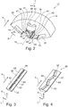
- a wind turbine 2 is shown schematically simplified in a sectional view.
- the wind turbine 2 has a housing 4, which is held by a mast 6 above the Erdbogens 8.
- an electric machine 10 is arranged, which has a substantially hollow cylindrical stator 12 which circumferentially surrounds a likewise hollow cylindrical rotor 14 designed.
- the rotor 14 has a number of non-illustrated permanent magnets and is rotatably supported by a shaft 16 about an axis of rotation 18.
- the rotor 14 is rotatably connected to the shaft 16, which is supported by means not shown ball bearings rotatably about the axis of rotation 18.
- the shaft 16 is designed substantially cylindrical and the stator 12, the rotor 14 and the shaft 16 are arranged concentrically with each other.
- the shaft 16 extends along an axial direction A which is parallel to the axis of rotation 18 and projects out of the housing 4.
- a hub 20 of a rotary wing rotor 22 is rotatably connected.
- wings 24 are connected, which extend with respect to the axis of rotation 18 in a radial direction R.
- the wind turbine 2 further comprises an inverter 26 which is mounted on the ground 8 and which is electrically contacted by means of an electrical line 28 to the electric machine 10.
- the rotary vane rotor 22 is caused to rotate about the rotation axis 18 due to a prevailing wind.
- the shaft 16 and the rotor 14 are rotated about the rotation axis 18.
- the permanent magnets of the rotor 14 induce in the stator 12 an electrical voltage which is applied to the converter 26 by means of the electrical line 28 becomes.
- the inverter 26 By means of the inverter 26, the electrical voltage is transformed to a specific value, and the resulting electric current is fed into a power network, not shown in detail.
- the electric machine 10 is a component of an injection molding machine, a drive of an industrial plant, a conveyor drive, another drive or a motor vehicle.
- FIG. 2 is fragmentary perspective and simplified illustrated the stator 12, which has a first laminated core 30.
- each of the sheets of the first laminated core 30 has the same shape, but at least the same cross section perpendicular to the axis of rotation 18.
- the individual sheets of the first laminated core 30 are made of electrical steel and electrically isolated from each other.
- the first laminated core 30 has a substantially hollow cylindrical shape and is arranged concentrically to the axis of rotation 18.
- the first laminated core 30 has a groove 32 extending in the axial direction A and running essentially in the radial direction R on the radial inner side thereof.
- the groove 32 has an opening 34 which is directed towards the axis of rotation 18.
- the groove 32 includes a bottom 36.
- the bottom 36 is offset relative to the opening 34 in the radial direction R.
- the cross section of the groove 32 perpendicular to the axis of rotation 18 is substantially rectangular. Also, the cross section of the groove 32 is perpendicular to the radial direction R rectangular.
- the groove 32 has a first side wall 38 extending in the axial direction A and a second side wall 40 extending in the axial direction A, each having a recess 42 extending in the axial direction A and extending in a tangential direction T in the region of the opening 34.
- the recesses 42 are in this case directed away from the interior of the groove 32, and each have the same distance from the bottom 36 of the groove 32 in the radial direction R.
- the recesses 42 each have a substantially rectangular, for example, square, cross-section and are groove-shaped.
- the first laminated core 30 further has a second groove 44 extending in the axial direction A, which runs parallel to the groove 32 and which is substantially identical to the groove 30.
- the first laminated core 30 has a tooth 46 which is accurate, or at least almost exactly (+/- 5 °, 2 °, 1 °, 0.5 °, 0 °), in the radial direction R runs, and its boundary in the tangential direction T by means of the second side wall 40 of the groove 32 and the first side wall 38 of the second groove 44 is formed.
- an electric coil 48 is inserted on the tooth 46.
- the tooth 46 is wound by the electric coil 48. Consequently, the electrical coil 48, which is made of a enameled copper wire, partially within the groove 32 and partially within the second groove 44 a.
- the electrical coil 48 is here in direct mechanical contact with the bottom 36 of the groove 32 and the second groove 44. That part of the electric coil 48, which rests in neither of the two grooves 32,44, is in the axial direction A on the first laminated core 30 across and is substantially U-shaped bent.
- the first laminated core 30 has a total of, as shown here, for example, eight such pairs of grooves, which are formed by the groove 32 and the second groove 44 and the tooth 46 disposed therebetween, and in the tangential direction T spaced apart and rotationally symmetrical with respect to the axis of rotation 18th are arranged.
- the stator 12 includes a total of eight such electrical coils 48.
- the number of coils 48 is equal to the number of groove pairs.
- the teeth 46, the electric coils 48 and the grooves 32, 44 are arranged rotationally symmetrically with respect to the axis of rotation 18. In other words, an angle of 45 ° is formed between each adjacent teeth 46, the apex of which lies on the axis of rotation 18.
- the stator 12 also has - as an example - sixteen slot closures 50, each groove 32 and each second groove 44 is associated with one of the slot closures 50.
- each groove closure 50 By means of each groove closure 50, the associated groove 32 and the second groove 44 is at least partially closed.
- the respective slot closure 50 is inserted in the axial direction A into the recesses 42 of the respective groove 32, 44, a clearance fit or an interference fit being created between them.
- the groove closure 50 is in Fig. 3 in perspective and in Fig. 10 shown in the assembled state in a sectional view perpendicular to the axis of rotation 18.
- the slot closure 50 has a second laminated core 52 which, by way of example, comprises three first metal sheets 54 and three second metal sheets 56.
- the three first sheets 54 are stacked in the radial direction R and fixed to each other, as well as the three second sheets 56.
- the two stacks formed in this way are joined to the second sheet stack 52 together.
- the second laminated core 52 is composed of laminations 54, 56 stacked in the radial direction R, which are fixed to one another by means of stamped packaging or gluing. All sheets 54,56 are made of the same material as the sheets of the first laminated core 30.
- the first sheets 54 each have a first shape and the second sheets 56 each have a second shape, wherein the two forms substantially only due to the expansion in Tangential direction T differ.
- the second plates 56 have a greater extent in the tangential direction T than the first plates 54 and are in the tangential direction T symmetric over the first plates 54 via.
- the second plates 56 are offset relative to the first plates 54 from the groove opening 34 in the direction of the bottom 36 of the respective groove 32,44 and lie at the radial end in the respective recess 42 a.
- the first sheets 54 adjoin the first side wall 38 in the tangential direction T and the second side wall 40 in the region which does not have the recess 42.
- the first plates 54 extend to the end of the respective groove 32,44 in the radial direction R, which is opposite the bottom 36, ie up to the slot opening 34th
- the second laminated core 52 is flush with the radially inner end of the laminated core 30, at least on the part of Tooth 46.
- the slot closure 50 further comprises an electrical insulation 58, which is attached to the second laminated core 52, and which consists for example of a plastic or a lacquer.
- the electrical insulation 58 is applied to the second laminated core 52 and forms the only direct mechanical contact between the first laminated core 30 and the slot closure 50.
- the second laminated core 52 is electrically insulated from the first laminated core 30 by means of the electrical insulation 58.
- the electrical insulation 58 is partially applied to the second laminated core 52 and is located only on the surfaces of the second laminated core 52, which faces the first side wall 38 and the second side wall 40 directly.
- the slot closure 50 consists of the second laminated core 52 and the electrical insulation 58.
- the slot closure 50 has - also by way of example - sixteen in the radial direction R extending recesses 60 which extend through the slot closure 50 completely therethrough.
- the recesses 60 in this case have a rectangular or rectangular cross section perpendicular to the radial direction R, wherein - if the cross section is rectangular - the recesses 60 extend in the axial direction A.
- the boundary edges of the cuboid cross section are parallel or perpendicular to the axial direction A.
- the individual recesses 60 are spaced apart from one another by means of webs 62, which extend substantially in the tangential direction T.
- the magnetic field 48 passing through the magnetic field is suitably shaped, to which mainly the second laminated core 52 contributes.
- the electrical insulation 58 By means of the electrical insulation 58, an electrical short circuit of the individual sheets of the first laminated core 30 and the second laminated core 52 is prevented, within which eddy currents are induced. Due to the recesses 60, a cogging torque of the rotor 14 can be reduced.
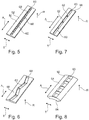
- Fig. 4 a further embodiment of the slot closure 50 is shown, wherein only the recesses 60 are modified.
- the slot closure 50 now has only four such recesses 60, which in the axial direction A to each other spaced apart and by means of tangentially extending T extending webs 62 are separated from each other.
- the recesses 60 continue to extend in the radial direction R.
- the recesses 60 extend obliquely to the axial direction A.
- the extension direction of each of the recesses 60 has both a component in the axial direction A and in the tangential direction T.
- the recesses 60 are arranged such that they form a zigzag pattern.
- the rotor 14 has four permanent magnets arranged adjacently in the axial direction, one of the recesses 60 being arranged in the radial direction R above one of the permanent magnets in each case. These four permanent magnets are preferably not offset in the tangential direction T to one another.
- Fig. 5 a further embodiment of the slot closure 50 is shown.
- the second laminated core 52 of this groove closure 50 no first sheets 54 and includes only the second sheets 56, which in turn eino in the mounting state in the recess 42 of the respective groove 32,44 at their respective end in the tangential direction T.
- manufacturing costs are reduced, and storage is simplified.
- Fig. 6 a further embodiment of the slot closure 50 is shown. Compared to the in Fig. 4 Also shown, this groove closure 50 has no first sheets 54, and the second laminated core 52 is formed only by means of the second sheets 56, as well as in Fig. 5 shown embodiment.
- Fig. 7 a further embodiment of the slot closure 50 is shown.
- the four recesses 60 extend in the axial direction A and consequently no zigzag pattern is formed. Due to this, a cogging torque of the rotor 14 is increased. Nevertheless, to obtain the cogging torque of the rotor 14, which by means of in Fig. 6 is obtained, for example, the four permanent magnets in Tangential direction T offset from each other. At the in Fig. 7 In the embodiment shown, the four permanent magnets are thus offset from each other both in the axial direction A and in the tangential direction T.
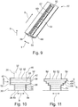
- a further embodiment of the groove closure 50 is shown, in which the four recesses 60 compared to the in Fig. 4 shown embodiment in the axial direction A, as well as in the Fig. 6 illustrated embodiment.
- the surfaces 64 which delimit the slot closure 50 in the radial direction R are arched and each formed by means of a circle segment whose center lies on the axis of rotation 18. As a result, the surface 64 facing away from the electric coil is curved.
- an air gap formed between the stator 12 and the rotor 14 substantially has a constant thickness in the radial direction R.
- a further embodiment of the slot closure 50 is shown in perspective.
- the second laminated core 52 has the first metal sheets 54 and the second metal sheets 56, which are stacked on one another in the radial direction R.
- the second laminated core 52 has four third sheets 66, which in comparison to the second sheets 56 have an enlarged in the direction of tangential expansion T.
- the third plates 66 are symmetrical in the tangential direction T via the second plates 56, just as they survive symmetrically over the first plates 54 in the tangential direction T. Consequently, the groove closure 50 in the tangential direction T has a triple-stepped end.
- the extending in the axial direction A four recesses 60 are executed in the tangential direction T edge-stepped. Due to the steps, the magnetic field passing through the electric coil 48 can be suitably shaped.
- Fig. 11 is a final embodiment of the groove closure 50 according to Fig. 10 shown.
- the second laminated core 52 has, by way of example, three first metal sheets 54, a second metal sheet 56, a third metal sheet 66 and a fourth metal sheet 68, the dimensions of which increase successively in the tangential direction T, and which in each case protrude symmetrically on both sides. Consequently, the slot closure 50 has a further stepped end in the tangential direction T. Due to the step shape is the slot closure 50 further stabilized within the recesses 42. All previously shown embodiments may include the four different sheets 54, 56, 66, 68.
- the in Fig. 11 shown embodiment of the slot closure 50 for example, the arrangement and shape of the recesses 60, which in Fig. 5, 6, 7 or 9 is shown. Alternatively or in combination, the surfaces 64 are curved.
Landscapes
- Engineering & Computer Science (AREA)
- Power Engineering (AREA)
- Iron Core Of Rotating Electric Machines (AREA)
Applications Claiming Priority (1)
| Application Number | Priority Date | Filing Date | Title |
|---|---|---|---|
| DE102016219739.8A DE102016219739A1 (de) | 2016-10-11 | 2016-10-11 | Elektrische Maschine |
Publications (1)
| Publication Number | Publication Date |
|---|---|
| EP3309934A1 true EP3309934A1 (fr) | 2018-04-18 |
Family
ID=59713933
Family Applications (1)
| Application Number | Title | Priority Date | Filing Date |
|---|---|---|---|
| EP17188143.6A Withdrawn EP3309934A1 (fr) | 2016-10-11 | 2017-08-28 | Machine électrique |
Country Status (3)
| Country | Link |
|---|---|
| EP (1) | EP3309934A1 (fr) |
| CN (1) | CN207782545U (fr) |
| DE (1) | DE102016219739A1 (fr) |
Cited By (1)
| Publication number | Priority date | Publication date | Assignee | Title |
|---|---|---|---|---|
| WO2026042552A1 (fr) * | 2024-08-19 | 2026-02-26 | 株式会社明電舎 | Induit et machine électrique tournante |
Families Citing this family (7)
| Publication number | Priority date | Publication date | Assignee | Title |
|---|---|---|---|---|
| DE102019103586A1 (de) * | 2019-02-13 | 2020-08-27 | Wobben Properties Gmbh | Nutverschlusskeil für einen Windenergieanlagengenerator sowie Windenergieanlagengenerator damit und Verfahren |
| DE102019209257A1 (de) * | 2019-06-26 | 2020-12-31 | Zf Friedrichshafen Ag | Stator für eine elektrische Maschine |
| CN110739801B (zh) * | 2019-11-15 | 2021-05-14 | 浙江安美德汽车配件有限公司 | 一种提高低速输出的汽车交流发电机 |
| DE102021133424A1 (de) | 2021-12-16 | 2023-06-22 | Bayerische Motoren Werke Aktiengesellschaft | Deckschieber für einen Schenkelpolrotor mit Schotten, Schenkelpolrotor sowie elektrische Maschine |
| DE102022204822A1 (de) | 2022-05-17 | 2023-11-23 | Zf Friedrichshafen Ag | Leistungserzeugende Komponente eines Elektromotors |
| DE102024100690A1 (de) * | 2024-01-11 | 2025-07-17 | Schaeffler Technologies AG & Co. KG | Stator mit dachförmigem Nutverschlusskörper zum Ableiten von Öl; sowie elektrische Maschine |
| DE102024102721A1 (de) * | 2024-01-31 | 2025-07-31 | Bayerische Motoren Werke Aktiengesellschaft | Stator für eine elektrische Maschine, insbesondere eines Kraftfahrzeugs, elektrische Maschine, insbesondere für ein Kraftfahrzeug, sowie Kraftfahrzeug |
Citations (9)
| Publication number | Priority date | Publication date | Assignee | Title |
|---|---|---|---|---|
| FR628551A (fr) * | 1926-04-08 | 1927-10-26 | Thomson Houston Comp Francaise | Perfectionnements aux shunts et clavettes magnétiques |
| GB847425A (en) * | 1957-04-08 | 1960-09-07 | Elektro Motoren A G | Structural member for conducting a magnetic flux |
| DE2015978A1 (de) * | 1970-03-28 | 1971-10-14 | Licentia Gmbh | Magnetischer Nutenverschluß fur elektrische Maschinen |
| JPS59175350A (ja) * | 1983-03-24 | 1984-10-04 | Shinko Electric Co Ltd | 磁性楔 |
| EP1659672A1 (fr) * | 2004-11-22 | 2006-05-24 | Minebea Co., Ltd. | Stator pour machine électrique, methode pour réaliser un stator et moteur à courant continu |
| WO2007100255A1 (fr) * | 2006-02-28 | 2007-09-07 | Smartmotor As | Machine electrique a stator comportant des dents rectangulaires et trapezoidales |
| EP2597758A2 (fr) * | 2011-11-25 | 2013-05-29 | Phase Motion Control S.p.A. | Moteur sans balais à PM avec commande d'inductance |
| JP2013132123A (ja) * | 2011-12-21 | 2013-07-04 | Toyota Industries Corp | 回転電機のステータ |
| WO2017163886A1 (fr) * | 2016-03-25 | 2017-09-28 | 三菱電機株式会社 | Armature pour machine électrique tournante |
Family Cites Families (3)
| Publication number | Priority date | Publication date | Assignee | Title |
|---|---|---|---|---|
| US4363982A (en) * | 1981-01-26 | 1982-12-14 | General Electric Company | Dual curved inlet gap pickup wedge |
| JPS57135642A (en) * | 1981-02-14 | 1982-08-21 | Matsushita Electric Ind Co Ltd | Rotor core for axial air gap type induction motor |
| US6218756B1 (en) * | 1999-10-28 | 2001-04-17 | Siemens Westinghouse Power Corporation | Generator rotor slot tightening method and associated apparatus |
-
2016
- 2016-10-11 DE DE102016219739.8A patent/DE102016219739A1/de not_active Withdrawn
-
2017
- 2017-08-28 EP EP17188143.6A patent/EP3309934A1/fr not_active Withdrawn
- 2017-10-10 CN CN201721304690.5U patent/CN207782545U/zh active Active
Patent Citations (9)
| Publication number | Priority date | Publication date | Assignee | Title |
|---|---|---|---|---|
| FR628551A (fr) * | 1926-04-08 | 1927-10-26 | Thomson Houston Comp Francaise | Perfectionnements aux shunts et clavettes magnétiques |
| GB847425A (en) * | 1957-04-08 | 1960-09-07 | Elektro Motoren A G | Structural member for conducting a magnetic flux |
| DE2015978A1 (de) * | 1970-03-28 | 1971-10-14 | Licentia Gmbh | Magnetischer Nutenverschluß fur elektrische Maschinen |
| JPS59175350A (ja) * | 1983-03-24 | 1984-10-04 | Shinko Electric Co Ltd | 磁性楔 |
| EP1659672A1 (fr) * | 2004-11-22 | 2006-05-24 | Minebea Co., Ltd. | Stator pour machine électrique, methode pour réaliser un stator et moteur à courant continu |
| WO2007100255A1 (fr) * | 2006-02-28 | 2007-09-07 | Smartmotor As | Machine electrique a stator comportant des dents rectangulaires et trapezoidales |
| EP2597758A2 (fr) * | 2011-11-25 | 2013-05-29 | Phase Motion Control S.p.A. | Moteur sans balais à PM avec commande d'inductance |
| JP2013132123A (ja) * | 2011-12-21 | 2013-07-04 | Toyota Industries Corp | 回転電機のステータ |
| WO2017163886A1 (fr) * | 2016-03-25 | 2017-09-28 | 三菱電機株式会社 | Armature pour machine électrique tournante |
Cited By (2)
| Publication number | Priority date | Publication date | Assignee | Title |
|---|---|---|---|---|
| WO2026042552A1 (fr) * | 2024-08-19 | 2026-02-26 | 株式会社明電舎 | Induit et machine électrique tournante |
| JP2026035021A (ja) * | 2024-08-19 | 2026-03-04 | 株式会社明電舎 | 電機子および回転電機 |
Also Published As
| Publication number | Publication date |
|---|---|
| DE102016219739A1 (de) | 2018-04-12 |
| CN207782545U (zh) | 2018-08-28 |
Similar Documents
| Publication | Publication Date | Title |
|---|---|---|
| EP3309934A1 (fr) | Machine électrique | |
| EP2005555B1 (fr) | Stator pour machine electrique multiphasee et procede pour sa fabrication | |
| EP3174183B1 (fr) | Machine électrique | |
| EP2619883B1 (fr) | Élément pour une machine électrique | |
| EP3499687B1 (fr) | Rotor d'une machine électrique | |
| WO1990009697A1 (fr) | Machine electrique excitee par des aimants permanents | |
| DE102018201591A1 (de) | Rotor | |
| DE102020124089A1 (de) | Modulare skalierbare elektrische maschine | |
| DE102017218153B3 (de) | Rotor einer elektrischen Maschine | |
| DE102022120479A1 (de) | Elektrische maschinen mit einem radial eingebetteten permanentmagnet-rotor und verfahren dazu | |
| EP2992589A2 (fr) | Rotor pour un moteur a reluctance et son procede de fabrication | |
| EP4699210A1 (fr) | Machine électrique dotée d'une structure de blindage permettant de réduire un couplage capacitif interne, et machine à flux axial ayant la structure de blindage | |
| EP1969697B1 (fr) | Machine électrique, notamment alternateur pour un véhicule automobile | |
| DE102023114966A1 (de) | Konstante elektrische maschinen mit variablem drehmoment mit einem radialspeichenrotor mit axialfluss-magnetplatten und verfahren dazu | |
| DE102010003127A1 (de) | Elektrische Maschine | |
| EP3669440B1 (fr) | Rotor d'une machine électrique | |
| WO2020007766A1 (fr) | Rotor | |
| EP2652862B1 (fr) | Élément de machine destiné à une machine électrique | |
| EP2296253A2 (fr) | Moteur électrique à excitation par aimants permanents avec couple de charge réduit | |
| DE102014011585A1 (de) | Elektrische Maschine | |
| EP3667871A1 (fr) | Machine électrique | |
| EP3472922B1 (fr) | Rotor pour une machine asynchrone électrique à cage d'écureuil surmoulée, machine électrique et procédé de fabrication | |
| EP3496236A1 (fr) | Rotor d'une machine électrique | |
| DE102022134556A1 (de) | Rotor für eine elektrische Maschine mit einem Magneten, der Vorsprünge aufweist | |
| DE102024209920A1 (de) | Stator für eine elektrische Maschine |
Legal Events
| Date | Code | Title | Description |
|---|---|---|---|
| PUAI | Public reference made under article 153(3) epc to a published international application that has entered the european phase |
Free format text: ORIGINAL CODE: 0009012 |
|
| AK | Designated contracting states |
Kind code of ref document: A1 Designated state(s): AL AT BE BG CH CY CZ DE DK EE ES FI FR GB GR HR HU IE IS IT LI LT LU LV MC MK MT NL NO PL PT RO RS SE SI SK SM TR |
|
| AX | Request for extension of the european patent |
Extension state: BA ME |
|
| 17P | Request for examination filed |
Effective date: 20180822 |
|
| RBV | Designated contracting states (corrected) |
Designated state(s): AL AT BE BG CH CY CZ DE DK EE ES FI FR GB GR HR HU IE IS IT LI LT LU LV MC MK MT NL NO PL PT RO RS SE SI SK SM TR |
|
| 17Q | First examination report despatched |
Effective date: 20190131 |
|
| STAA | Information on the status of an ep patent application or granted ep patent |
Free format text: STATUS: THE APPLICATION HAS BEEN WITHDRAWN |
|
| 18W | Application withdrawn |
Effective date: 20190520 |