EP3176055A2 - Couvre-volant - Google Patents
Couvre-volant Download PDFInfo
- Publication number
- EP3176055A2 EP3176055A2 EP16002341.2A EP16002341A EP3176055A2 EP 3176055 A2 EP3176055 A2 EP 3176055A2 EP 16002341 A EP16002341 A EP 16002341A EP 3176055 A2 EP3176055 A2 EP 3176055A2
- Authority
- EP
- European Patent Office
- Prior art keywords
- layer
- steering wheel
- shielding layer
- sensor
- conductive
- Prior art date
- Legal status (The legal status is an assumption and is not a legal conclusion. Google has not performed a legal analysis and makes no representation as to the accuracy of the status listed.)
- Granted
Links
Images


Classifications
-
- B—PERFORMING OPERATIONS; TRANSPORTING
- B62—LAND VEHICLES FOR TRAVELLING OTHERWISE THAN ON RAILS
- B62D—MOTOR VEHICLES; TRAILERS
- B62D1/00—Steering controls, i.e. means for initiating a change of direction of the vehicle
- B62D1/02—Steering controls, i.e. means for initiating a change of direction of the vehicle vehicle-mounted
- B62D1/04—Hand wheels
- B62D1/046—Adaptations on rotatable parts of the steering wheel for accommodation of switches
-
- B—PERFORMING OPERATIONS; TRANSPORTING
- B62—LAND VEHICLES FOR TRAVELLING OTHERWISE THAN ON RAILS
- B62D—MOTOR VEHICLES; TRAILERS
- B62D1/00—Steering controls, i.e. means for initiating a change of direction of the vehicle
- B62D1/02—Steering controls, i.e. means for initiating a change of direction of the vehicle vehicle-mounted
- B62D1/04—Hand wheels
- B62D1/06—Rims, e.g. with heating means; Rim covers
-
- G—PHYSICS
- G01—MEASURING; TESTING
- G01D—MEASURING NOT SPECIALLY ADAPTED FOR A SPECIFIC VARIABLE; ARRANGEMENTS FOR MEASURING TWO OR MORE VARIABLES NOT COVERED IN A SINGLE OTHER SUBCLASS; TARIFF METERING APPARATUS; MEASURING OR TESTING NOT OTHERWISE PROVIDED FOR
- G01D5/00—Mechanical means for transferring the output of a sensing member; Means for converting the output of a sensing member to another variable where the form or nature of the sensing member does not constrain the means for converting; Transducers not specially adapted for a specific variable
- G01D5/12—Mechanical means for transferring the output of a sensing member; Means for converting the output of a sensing member to another variable where the form or nature of the sensing member does not constrain the means for converting; Transducers not specially adapted for a specific variable using electric or magnetic means
- G01D5/14—Mechanical means for transferring the output of a sensing member; Means for converting the output of a sensing member to another variable where the form or nature of the sensing member does not constrain the means for converting; Transducers not specially adapted for a specific variable using electric or magnetic means influencing the magnitude of a current or voltage
- G01D5/24—Mechanical means for transferring the output of a sensing member; Means for converting the output of a sensing member to another variable where the form or nature of the sensing member does not constrain the means for converting; Transducers not specially adapted for a specific variable using electric or magnetic means influencing the magnitude of a current or voltage by varying capacitance
-
- H—ELECTRICITY
- H05—ELECTRIC TECHNIQUES NOT OTHERWISE PROVIDED FOR
- H05K—PRINTED CIRCUITS; CASINGS OR CONSTRUCTIONAL DETAILS OF ELECTRIC APPARATUS; MANUFACTURE OF ASSEMBLAGES OF ELECTRICAL COMPONENTS
- H05K9/00—Screening of apparatus or components against electric or magnetic fields
- H05K9/0073—Shielding materials
- H05K9/0081—Electromagnetic shielding materials, e.g. EMI, RFI shielding
- H05K9/009—Electromagnetic shielding materials, e.g. EMI, RFI shielding comprising electro-conductive fibres, e.g. metal fibres, carbon fibres, metallised textile fibres, electro-conductive mesh, woven, non-woven mat, fleece, cross-linked
Definitions
- the present invention relates to a steering wheel casing according to the preamble of claim 1 and the preamble of claim 2.
- These steering wheel shells are used because of their construction as part of an arrangement with which it is detected whether a driver's hand is on the steering wheel, by a Evaluation unit, the impedance between an electrode within the steering wheel casing and the vehicle body is determined.
- Such a steering wheel casing has a multi-layered structure, which has a circumferential length and a cross-sectional width in the development in a plane.
- the circumferential length is associated with the outer periphery of a steering wheel rim to be related to the steering wheel casing and the cross-sectional width is the outer diameter, seen in the cross-sectional direction of the steering wheel rim assigned.
- the steering wheel casing is of a multi-layered construction, whereby the layers overlap one another, at least partially, in projection.
- the layer sequence comprises a lower, facing towards the steering wheel core, electrically conductive shielding layer, followed, seen in the direction of an upper, the outer steering wheel cover associated cover layer of a shielding layer, an insulating layer and at least one electrically conductive sensor layer.
- the shielding layer and / or the sensor layer have a conductor structure with circumferentially extending and in cross-sectional width extending conductors; the shielding layer and the sensor layer are electrically connected to connecting conductors of a connecting cable.
- the DE 203 09 603 U1 describes a steering device, ie a steering wheel for a motor vehicle.
- the steering wheel has a sensor device, which is designed as a capacitive sensor element, which is arranged in the region of the steering wheel rim of the steering wheel.
- This sensor device serves to detect the approach and / or contact of the steering wheel rim by a driver's hand by changing the capacitance of the sensor element to also determine whether the hand of a vehicle occupant completely or only partially on the steering wheel or only is located near the steering wheel and whether the steering wheel is covered with the full hand or is touched only by individual fingers.
- the sensor device is covered by a steering wheel cover or a steering wheel cover made of a leather or plastic material and constructed from a ladder assembly, which is designed for example as around the steering wheel rim wound around electrically conductive wire.
- This conductor arrangement acts as a capacitive sensor device.
- the signals are detected by an evaluation, which can be arranged in the central steering wheel area.
- the sensor device can also be constructed by a conductive network structure or by ribbon conductors.
- the steering wheel rim is divided into sections to enable spatially resolved detection. It is also envisaged that the conductor arrangement also serves as a heating device.
- the DE 10 2009 058 138 A1 describes a method of manufacturing a proximity sensor for a vehicle intended for a steering wheel in a vehicle.
- This proximity sensor has an upper fabric layer, in which conductive warp threads are incorporated, a lower fabric layer, in which conductive weft threads are incorporated, and a middle fabric layer of non-conductive threads, which isolates the upper and lower fabric layers against each other.
- the upper and lower fabric layers are each connected via a connection with an evaluation unit.
- the total capacity of this arrangement is composed of the capacity of the three layers of fabric as well as a capacity which varies with the distance of a finger or a hand from the arrangement.
- the DE 10 2011 084 903 A1 is directed to sensor systems for a motor vehicle, also for installation in a steering wheel, which additionally has a heating device, with a capacitive sensor element, the interference by parasitic capacitances should avoid or minimize.
- this sensor element on the steering wheel rim of a steering wheel, which is additionally heated, wherein the steering wheel rim of a metal skeleton, which is surrounded by a dielectric, constructed, is located on the dielectric, a heating layer, which is covered on the outside of a shielding , followed by a sensor layer, which in turn is enveloped by a reference of the steering wheel.
- a heating conductor of the heating conductor and / or a sensor conductor of the capacitive sensor element may be formed as sewing threads.
- a metal mesh formed by warp wires and weft wires may be used for the shielding layer.
- Another sensor system for a steering wheel of a vehicle is in the US 2012/0326735 A1 and includes a first sensor disposed within a left front portion of the steering wheel to detect contact of the left front portion of the steering wheel and a second sensor disposed within a right front portion of the steering wheel is to detect a contact of the right front part of the steering wheel, separate from the first area. Furthermore, a third sensor is provided which is associated with the rear of the steering wheel to detect a contact of the rear portion of the steering wheel. Via the three sensors, a touch of the respective area, which are assigned to the sensors, can be detected with the hand of a driver, whereby also a touch by the driver, which does not occur with the hand, should be distinguished. As a sensor complex impedance sensors can be used.
- the DE 203 09 877 U1 is directed to a vehicle safety system in which at least one capacitive sensor, preferably a plurality of sensors, are integrated in the steering wheel rim of a steering wheel.
- the sensors detect a change in an electric or electromagnetic field.
- the sensors are between the envelope, for example, a PUR foam, a steering wheel skeleton and the steering wheel rim to the outside final wrapping in the form of a flexible foam layer, a leather or Holzumhüllung. It is also contemplated that the sensors are formed by at least a portion of a steering wheel heater. When using multiple sensors can draw conclusions about the position the upper body or the head of a driver are pulled relative to the axis of rotation of the steering wheel.
- the sensors may be constructed as a flexible mat having elongate electrical conductors received therein. Also, such a sensor may include a nonwoven mat.
- the present invention has for its object to provide a steering wheel casing with a sensor arrangement, which are particularly well suited by their construction and / or by the material used for their arrangement on a steering wheel.
- the steering wheel casing of the invention is characterized according to an inventive concept in that the electrical connection of the respective connection conductor of the connection cable with the shielding layer and / or the sensor layer is formed in each case via a metal foil.
- a metal foil in the region of which an electrical connection of a connecting cable with the respective shielding layer or sensor layer is made, electrical contacting of these layers is ensured.
- the metal foil does not bear under the reference of the steering wheel, in particular of the steering wheel rim, and is therefore not distinguished by the steering wheel cover on the outside thereof.
- the contacting region with the metal foil is preferably arranged in the spoke area of the steering wheel.
- the metal foil is characterized by their flexibility, to adapt to the rounding of the steering wheel rim.
- the size of this metal foil is preferably chosen so that its length and / or width at least equal to three times the distance of the adjacent, non-conductive warp threads.
- the invention is also characterized in that the shielding layer and / or the sensor layer has a knitted structure with non-conductive, loop-forming warp threads and with conductive weft threads.
- the weft threads should contain at least one conductive material.
- this structure of the steering wheel casing has the advantage that it can be adapted to the steering wheel rim to which it is applied at any point, in particular in view of the fact that it has a good stretching behavior both in the peripheral length as a result of the knitted structure of the shielding layer and / or the sensor layer Also seen in the cross-sectional width, in the settlement, and thus seen in the circumferential direction of the steering wheel rim and in the direction of the cross section of the steering wheel rim owns.
- the metal foil covers a plurality of conductors of the respective conductor structure of the shielding layer or of the sensor layer, the length or width of the metal foil also preferably corresponding to at least three times the spacing of the adjacent, non-conducting warp threads.
- the dimensions of the metal foil can also be dimensioned with respect to their length and / or their width at a stitch interval of stitches with which conductive threads in the shielding layer and / or the sensor layer are held on a carrier material; the respective dimension is then at least five times the stitch spacing of the conductive thread.
- the metal foil is connected by means of electrically conductive adhesive to the conductors of the respective conductor structure.
- electrically conductive adhesive penetrates the structure of the shield layer or the sensor layer and achieves additional contact areas between the electrically conductive conductors of the conductor pattern.
- connection region of the shielding layer and / or the sensor layer are extended in the region in which they are connected to the connection conductors of the connection cable in such a way that they have the shape of a tab.
- This tab can be positioned in the steering wheel casing wrapped around the steering wheel core so that it can be oriented or guided in the region of a spoke of the steering wheel to the region of the steering wheel hub.
- the tab can be made in a rectangular shape. But it is also intended to carry out the tab with a trapezoidal outer contour or an oval outer contour, so that it narrows towards its free end.
- the tab may have a length to width ratio of 10: 1 to 1:10; Preferably, the tab has only a small length, but a large width, along which they connected to the main surface, so that a ratio of length to width of 1:10 to 2: 5 should be maintained.
- connection cable can be formed as a coaxial cable with an inner conductor and a coaxial cable shield and an outer protective sheath.
- the inner conductor forms the connecting conductor connected to the sensor layer
- the cable shield forms the connecting conductor connected to the shielding layer.
- the coaxial cable prevents or at least largely suppresses extraneous disturbing influences which can act on the connection conductors due to the environment.
- the shielding layer and / or the sensor layer can be formed from a conductive textile which is suitable for the circumstances, i. for example, the shape of the steering wheel core, adapt.
- a conductive textile may comprise metallized textile fibers.
- fibers made of silver-plated PA66 yarn with a resistance of less than 500 ohm / m.
- fibers with a resistance of less than 1000 ohms / m are possible.
- the conductive fabric may include metal and / or metal alloy wires as conductive fibers.
- the sensor layer and the shielding layer with the intervening insulating layer are dimensioned and spaced from each other to form a capacitor having a capacitance of at least 100 pF.
- the insulating layer should be formed so that the sensor layer is above the shielding layer and does not penetrate into it, so as to achieve a complete shielding of the steering wheel rim.
- the sensor layer is dimensioned such that it is smaller in area than the shielding layer.
- the sensor layer should be projected onto the shielding layer at least on one side, in cross-sectional width, i. in the direction of the cross-sectional circumference of the steering wheel rim, be smaller than the shielding layer.
- the textile material is particularly well suited for the sheath and the intended use, this is constructed such that weft threads of the textile material between warp threads of the textile material, in such a way that each weft thread is at least the next adjacent weft thread in an electrical connection.
- Such a material is characterized by its particularly good expansion behavior and low material usage.
- the conductive weft threads In another textile material, which is to be regarded as preferred for certain applications, run between adjacent and spaced, non-conductive warp threads, the conductive weft threads.
- the warp threads can be processed in tricot technique or in fringe technique to the respective textile layer.
- the material used for the warp threads is polyester.
- the spacing of adjacent warp threads may be in the range of about 1 to 10 mm, with a spacing in the range of 3 to 5 mm being preferred.
- the material used for the weft threads are preferably those made of PA6.6 (polyamide 6.6), which show very good mechanical properties in terms of stiffness and hardness, abrasion, strength and heat resistance, with a metallic layer, preferably a silver coating.
- the conductivity of the weft threads should be less than 500 ohm / m.
- the weft threads are preferably processed so that a mean distance between adjacent weft threads, viewed in the direction of the course of the warp threads, is between 0.5 and 1.5 mm.
- weft threads are used, which consist of a mutually different electrically conductive material.
- weft threads meander between at least two adjacent warp threads
- weft threads of different conductivity alternate between adjacent warp threads.
- the weft threads of conductivity extend meandering between up to 10, preferably up to 5, adjacent and substantially parallel warp threads, before weft threads of the other conductivity extend between adjoining warp threads. Accordingly, a weft thread can span a plurality of warp threads.
- the meander of the respective weft thread seen in the direction of the course of the warp threads, have an average distance of 0.5 to 1.5 mm.
- An area of Weft threads with these distances can alternate with an adjacent area, in which the meander of the weft threads have an average distance of 1.5 to 10 mm.
- the materials of the weft threads of the respective regions may also be the same.
- weft threads have metallized plastic fibers.
- weft threads on wires of metal or of a metal alloy are provided.
- the thickness of the metal foil should be in the range of 10 to 200 ⁇ m, preferably in the range of 10 to 100 ⁇ m.
- the sensor layer and / or the shielding layer can consist of a metal foil which is structured by cuts such that it can be stretched in at least one direction of its surface.
- such a metal foil should have a thickness in the range of 10 to 200 microns with a preferred thickness of 10 to 100 microns.
- This extensibility can also be achieved with a metal foil suitable for material and thickness by forming an embossed structure with embossments in a direction perpendicular to the base surface of the metal foil flattening to stretch the foil to the base of the metal foil. has.
- the thickness of such embossed metal foils is also in the range of 10 to 200 microns and 10 to 100 microns. Structuring of the metal foil may also be effected by etching by etching the above-mentioned cuts in the material of the metal foil.
- an adhesive material can be used which connects the layers at least pointwise.
- an adhesive material for fixing the layers in position can be a two-sided adhesive layer, for example, a double-sided adhesive tape may be used.
- an adhesive fleece or a hot melt adhesive is provided.
- a polyurethane (PU) foam, a terpolymer elastomer, a non-woven or a film can be used as the material for the cover layer.
- the material used is matched to the feel that is to be achieved on the steering wheel.
- a cover layer on a polyurethane (PU) foam is preferred when a soft feel is desired.
- a terpolymeric elastomer (rubber) is, inter alia, an EPDM (ethylene-propylene-diene rubber).
- EPDM and EPM ethylene-propylene rubber
- EPDM and EPM ethylene-propylene rubber
- the insulating layer As a material for the insulating layer is a terpolymeres elastomer (rubber), a non-woven, a film, a sponge rubber or a PU foam, preferably a closed-pore foam provided. In any case, it must be ensured that the insulation layer should primarily be electrically insulated. If a film material is used for the cover layer, this should have a thickness of 10 .mu.m to 200 .mu.m, preferably from 20 .mu.m to 50 .mu.m.
- At least one electrically conductive adhesive tape can be positioned between the insulating layer and the sensor layer and / or between the insulating layer and the shielding layer. With this measure it is also achieved that a larger area of the respective layer is additionally bridged by the cover.
- the conductivity of the corresponding adhesive layer should preferably be in the range of less than 50 kOhm / square.
- a substantially identical structure which also relates to the structure of these layers, is selected for the shielding layer and the sensor layer.
- the shielding layer and / or the sensor layer may additionally comprise conductive graphite or metal particles which can / can be incorporated in the layers.
- a further insulation layer is arranged, viewed in the direction of the steering wheel core, which separates the heating layer from the further layers, i. H. the shielding layer and the sensor layer, separates.
- the steering wheel casing 1, as in FIG. 1 is shown, has a multilayer structure.
- This steering wheel casing 1 is on a steering wheel rim 2 of a steering wheel 3, the in FIG. 2 is shown arranged.
- Such a steering wheel rim 2 is held on steering wheel spokes 4 to a steering wheel hub in the region of a central baffle 5.
- the steering wheel casing 1 comprises a lower shielding layer 6, which is oriented toward a steering wheel core of the steering wheel rim 2, and an upper cover layer 7, which points towards a steering wheel cover, not shown.
- an insulating layer 8 and a sensor layer 9 Located between the shielding layer 6 and the cover layer 7 of the steering wheel casing 1, seen from the shielding layer 6 in the direction of the cover layer 7 and thus in the direction of the steering wheel cover, not shown, an insulating layer 8 and a sensor layer 9. Both between the shielding layer 6 and the insulating layer as well as between the insulating layer 8 and the sensor layer 9 and the sensor layer 9 and the cover layer 7, an adhesive layer 10 is arranged in each case, preferably used for a double-sided adhesive material layer, comparable to a double-sided adhesive tape.
- the sensor layer 9 has an areal size which is smaller than the area of the shielding layer 6, so that the shielding layer 6, viewed in projection onto the sensor layer 9, covers this sensor layer 9 in such a way that on all four sides, at least however on three sides or two sides, an edge region of the shielding layer 6 remains.
- This remaining margin can also be clearly recognized by the fact that the adhesive layer 10 interposed between the insulating layer 8 and the sensor layer 9 and corresponding in size to the size of the insulating layer 8 and the size of the shielding layer 6 has an adhesive edge which is not is covered by the sensor layer 9.
- the surface dimensions of the individual layers 6, 7, 8 and 10 are chosen so that they are substantially congruent, while only the sensor layer 9 is smaller in size.
- the individual layers 6, 7, 8 and 10 have a circumferential length and a cross-sectional width in their development such that these layers overlap one another at least partially in projection.
- the circumferential length of the layers results from the outer circumference of the steering wheel rim 2 of the steering wheel 3 in FIG. 2 , which is designated by the circumferential arrow 11, while the cross-sectional width of the circumference of the Cross section of the steering wheel rim 2, in FIG. 2 with the reference numeral 12 corresponds.
- the shielding layer 6 and / or the sensor layer 9 is / are made up of a conductor structure which, for example, in FIG FIG. 3 is shown. They preferably consist essentially of a conductive knitted fabric.
- a material for the cover layer 7 is a thin layer of a polyurethane foam (polyurethane foam), a nonwoven with a high compression hardness or a film.
- the cover layer 7 is intended to prevent parts of the underlying layers from being marked by a steering wheel cover.
- a PU foam mat (polyurethane foam mat) which sufficiently insulates the shielding layer 6 and the sensor layer 9 against each other.
- a film or a non-woven for example, according to the material of the cover layer 7, can be used.
- Preferred is a structure in which the cover layer 7 and the insulating layer 8 are identical with respect to the material used; just with such a structure, the cover layer 7 may be slightly thicker than the insulating layer 8, in which case a cover layer 7 is twice as thick as the insulating layer 8 is preferred.
- connection region 13 is indicated both on the shielding layer 6 and on the sensor layer 9, in the region of which in each case one connection conductor of a connection cable is electrically connected to the respective conductor structure.
- This connection region 13 lies in each case at the edge of the respective layer 6 and 9.
- connection regions 13 of the respective layers 6 and 9 can be arranged offset laterally in projection, so that on the one hand, the thickness of the overall structure does not increase significantly when a connection cable is connected and, on the other hand, a simpler installation of the respective connection cable is possible.
- connection regions 13 of the respective layers 6 and 9, seen in projection one upon the other not be possible for reasons of space, then an arrangement of the connection regions 13 of the respective layers 6 and 9, seen in projection on each other, also possible on top of each other, like this one FIG. 1 shows.
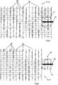
- the FIG. 3 shows a structure of a conductor structure of the sensor layer 9 or the shielding layer 6 with substantially parallel warp threads 14 made of a non-conductive material, between which electrically conductive weft threads 15 extend.
- the weft threads 15 which extend between two warp threads 14 are in contact with the weft threads 15 on the other side of the respective warp thread 14 or are processed in the layer such that they are electrically connected to one another.
- a material for the conductive weft threads 15 a silver-plated yarn, ie, one having a surface coating of silver, can be used.
- the resistance of the yarn for the conductive weft yarns 15 is preferably between 500 ohms / m and 1000 ohms / m, using, if possible, yarns having the smaller values.
- the warp threads 14 and the weft threads 15 are processed in a fringe bond. It is also provided to process the warp threads 14 and the weft threads 15 in a tricot binding. With both techniques, a course of the warp threads 14 and the weft threads 15 can be achieved, which is schematically in FIG. 3 is shown.
- FIGS. 5 and 6 show a section of a ladder structure comparable to the one in FIG. 3 is shown. Even with this conductor structure, the individual conductors can represent warp threads 14 and weft threads 15. However, the conductor structure can also be assigned to another structure of the shielding layer 6 and the sensor layer 9, since the FIGS. 5 and 6 serve to connect the connection of the layer of the conductive structure with a connecting conductor 16 of a connecting cable.
- connection conductor 16 is connected to the conductor structure such that it covers a plurality of conductors, for example a region which extends over at least three warp threads 14, when the conductor structure of the FIG. 5 both warp threads 14 and intervening weft threads 15 is assigned.
- the connection conductor 16 preferably runs in such a way that it is arranged substantially orthogonal to the course of the warp threads 14. As a result, he stands with the weft threads 15, the between these warp threads 14, in electrical connection.
- a metal foil is applied to the conductor structure, which is indicated by a rectangle in a broken line 17.
- This metal foil 17 assigned to the rectangle ensures a larger contacting area of the electrically conductive structures of the shielding layer 6 or the sensor layer 9 and connects this area to the connecting conductor 16.
- the connecting conductor 16 is formed on the outside of the metal foil 17, ie on the side, which faces away from the conductor structure, attached and electrically connected thereto.
- the connection conductor 16 can also be interposed between the metal foil 17 and the conductor structure, in particular when the connection conductor 16 is designed as a thin, flat conductor track;
- This conductor can consist of a copper foil from which the metal foil 17 can be constructed.
- Such a metal foil 17 can additionally be coated with a silver layer, for example vapor-coated.
- this tab 18 preferably has a conductor structure or a material structure corresponding to the further surface of the respective layer 6 or 9.
- This tab 18 may also be formed by a metal foil 17 according to the embodiment of FIG. 5 be covered, with the advantages that are described above on the basis of FIG. 5 are described. This also relates to the size of the metal foil 17 and thus also to the size of the tab 18.
- the metal foil 17 may also cover a part of the edge of the main surface of the respective layer and thus the conductor structure, so that they the tab 18 and the Connection of the tab 18 with the further conductor structure of the shielding layer 6 and sensor layer 9 gives an additional strength.
- a conductive adhesive may be applied to additionally interconnect a plurality of conductors of the conductive pattern and to obtain an even larger contact area with the metal foil 17.
- the connecting conductor 16 can also be secured to the mat via a cover made of a fleece or a hot melt adhesive. It is also provided, the connection conductor 16 in the region of the connection surface (broken line 17 in FIG. 5 or in FIG. 6 ) in one or more loops and fix in order to achieve additional strain relief of the contact areas.
- the feed line and the connecting conductor 16 are soldered, welded or preferably fastened in the connection region with a crimp connection.
- a coaxial cable should be used in order to avoid interference.
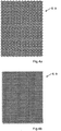
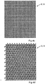
- FIGS. 4a to 4d show different sections of differently structured metal foils, which can be used for the shielding.
- These metal foils have punching lines in the form of meanders, star-shaped beams, and the like, in particular in the form of Greek meanders or Greek double meanders, so that contiguous and thus interconnected metal structures remain.
- Such metal foils show a stretching behavior and thus a flexibility, so that they adapt well to the conditions on the steering wheel 2.
Landscapes
- Engineering & Computer Science (AREA)
- Chemical & Material Sciences (AREA)
- Combustion & Propulsion (AREA)
- Transportation (AREA)
- Mechanical Engineering (AREA)
- Physics & Mathematics (AREA)
- General Physics & Mathematics (AREA)
- Textile Engineering (AREA)
- Electromagnetism (AREA)
- Microelectronics & Electronic Packaging (AREA)
- Steering Controls (AREA)
- Shielding Devices Or Components To Electric Or Magnetic Fields (AREA)
Priority Applications (1)
| Application Number | Priority Date | Filing Date | Title |
|---|---|---|---|
| EP18000421.0A EP3375693B1 (fr) | 2015-11-16 | 2016-11-03 | Couvre-volant |
Applications Claiming Priority (1)
| Application Number | Priority Date | Filing Date | Title |
|---|---|---|---|
| DE202015007837.0U DE202015007837U1 (de) | 2015-11-16 | 2015-11-16 | Lenkradummantelung |
Related Child Applications (2)
| Application Number | Title | Priority Date | Filing Date |
|---|---|---|---|
| EP18000421.0A Division-Into EP3375693B1 (fr) | 2015-11-16 | 2016-11-03 | Couvre-volant |
| EP18000421.0A Division EP3375693B1 (fr) | 2015-11-16 | 2016-11-03 | Couvre-volant |
Publications (3)
| Publication Number | Publication Date |
|---|---|
| EP3176055A2 true EP3176055A2 (fr) | 2017-06-07 |
| EP3176055A3 EP3176055A3 (fr) | 2017-11-15 |
| EP3176055B1 EP3176055B1 (fr) | 2019-05-22 |
Family
ID=57233271
Family Applications (2)
| Application Number | Title | Priority Date | Filing Date |
|---|---|---|---|
| EP16002341.2A Active EP3176055B1 (fr) | 2015-11-16 | 2016-11-03 | Couvre-volant |
| EP18000421.0A Active EP3375693B1 (fr) | 2015-11-16 | 2016-11-03 | Couvre-volant |
Family Applications After (1)
| Application Number | Title | Priority Date | Filing Date |
|---|---|---|---|
| EP18000421.0A Active EP3375693B1 (fr) | 2015-11-16 | 2016-11-03 | Couvre-volant |
Country Status (4)
| Country | Link |
|---|---|
| US (1) | US10370019B2 (fr) |
| EP (2) | EP3176055B1 (fr) |
| DE (1) | DE202015007837U1 (fr) |
| ES (1) | ES2742735T3 (fr) |
Families Citing this family (29)
| Publication number | Priority date | Publication date | Assignee | Title |
|---|---|---|---|---|
| US10272836B2 (en) | 2017-06-28 | 2019-04-30 | Honda Motor Co., Ltd. | Smart functional leather for steering wheel and dash board |
| US10953793B2 (en) | 2017-06-28 | 2021-03-23 | Honda Motor Co., Ltd. | Haptic function leather component and method of making the same |
| US11225191B2 (en) | 2017-06-28 | 2022-01-18 | Honda Motor Co., Ltd. | Smart leather with wireless power |
| US11665830B2 (en) | 2017-06-28 | 2023-05-30 | Honda Motor Co., Ltd. | Method of making smart functional leather |
| US10742061B2 (en) * | 2017-06-28 | 2020-08-11 | Honda Motor Co., Ltd. | Smart functional leather for recharging a portable electronic device |
| US10682952B2 (en) | 2017-06-28 | 2020-06-16 | Honda Motor Co., Ltd. | Embossed smart functional premium natural leather |
| JP6511210B1 (ja) * | 2017-10-19 | 2019-05-15 | 住友理工株式会社 | 静電容量結合方式センサおよびその製造方法 |
| WO2019147800A2 (fr) | 2018-01-24 | 2019-08-01 | Gentherm Inc. | Système de détection et de chauffage capacitif pour des volants ou des sièges pour détecter la présence d'une main d'un occupant sur un volant ou d'un occupant dans un siège |
| JP6992951B2 (ja) * | 2018-03-22 | 2022-01-13 | 株式会社東海理化電機製作所 | ステアリング体 |
| US10625765B2 (en) * | 2018-09-20 | 2020-04-21 | Darlene Love | Reflective steering wheel cover and method |
| JP6714788B1 (ja) * | 2018-09-26 | 2020-06-24 | 住友理工株式会社 | 静電容量センサ、その製造方法、および静電容量センサ用網目状柔軟電極 |
| IT201800010784A1 (it) * | 2018-12-04 | 2020-06-04 | Irca Spa | Dispositivo di riscaldamento e rilevamento per rilevare un contatto tra un utente e un volante di un veicolo e per riscaldare il volante |
| DE102018222551A1 (de) * | 2018-12-20 | 2020-06-25 | Joyson Safety Systems Germany Gmbh | Lenkrad für ein Kraftfahrzeug und Verfahren zum Herstellen eines Lenkrads |
| US11751337B2 (en) | 2019-04-26 | 2023-09-05 | Honda Motor Co., Ltd. | Wireless power of in-mold electronics and the application within a vehicle |
| FR3100018B1 (fr) * | 2019-08-23 | 2021-07-23 | Autoliv Dev | Volant de véhicule |
| KR102869463B1 (ko) * | 2019-10-31 | 2025-10-13 | 현대자동차주식회사 | 부직포 적용 조향 휠 hod 커버 |
| JP7554050B2 (ja) * | 2020-01-14 | 2024-09-19 | 株式会社東海理化電機製作所 | 加飾体 |
| JP7425630B2 (ja) | 2020-03-05 | 2024-01-31 | 株式会社東海理化電機製作所 | 検出機構 |
| JP7481192B2 (ja) * | 2020-07-30 | 2024-05-10 | Joyson Safety Systems Japan合同会社 | ステアリング把持センサ及びステアリング |
| CN112249146A (zh) * | 2020-11-10 | 2021-01-22 | 锦州锦恒汽车安全系统股份有限公司 | 一种离手检测方向盘 |
| CN112882106A (zh) * | 2021-01-15 | 2021-06-01 | 安闻汽车技术(天津)有限公司 | 一种具有人体探测功能的方向盘传感器及方向盘 |
| DE202021002074U1 (de) | 2021-06-16 | 2022-06-13 | I.G. Bauerhin Gmbh | Lenkradummantelung |
| JP7573503B2 (ja) * | 2021-09-27 | 2024-10-25 | 株式会社東海理化電機製作所 | 検出機構 |
| US12480787B2 (en) | 2022-07-05 | 2025-11-25 | Pixart Imaging Inc. | Touch sensing system, multi sensor device and vehicle control device |
| US12195073B2 (en) | 2022-07-05 | 2025-01-14 | Pixart Imaging Inc. | Pressure sensing device, 3D gesture control system and vehicle control system |
| JP2024022348A (ja) * | 2022-08-05 | 2024-02-16 | 株式会社東海理化電機製作所 | 検出機構 |
| JP2025042391A (ja) * | 2023-09-14 | 2025-03-27 | 株式会社東海理化電機製作所 | ステアリングカバー |
| KR102883064B1 (ko) * | 2023-09-27 | 2025-11-07 | 주식회사 코모스 | 파지감지 스티어링 휠의 hod 매트 검사 방법 및 시스템 |
| US12570350B2 (en) * | 2024-08-26 | 2026-03-10 | Pixart Imaging Inc. | Sensing steering wheel |
Citations (5)
| Publication number | Priority date | Publication date | Assignee | Title |
|---|---|---|---|---|
| DE20309603U1 (de) | 2003-06-18 | 2003-09-25 | TAKATA-PETRI AG, 63743 Aschaffenburg | Lenkeinrichtung für ein Kraftfahrzeug |
| DE20309877U1 (de) | 2003-06-26 | 2003-10-30 | TRW Automotive Safety Systems GmbH, 63743 Aschaffenburg | Fahrzeugsicherheitssystem |
| DE102009058138A1 (de) | 2009-12-12 | 2011-06-16 | Volkswagen Ag | Verfahren zur Herstellung eines Näherungssensors für ein Fahrzeug, Näherungssensor, Lenkrad und Fahrzeug |
| US20120326735A1 (en) | 2011-06-22 | 2012-12-27 | Tk Holdings Inc. | Sensor system for steering wheel for vehicle |
| DE102011084903A1 (de) | 2011-10-20 | 2013-04-25 | TAKATA Aktiengesellschaft | Sensorsysteme für ein Kraftfahrzeug |
Family Cites Families (4)
| Publication number | Priority date | Publication date | Assignee | Title |
|---|---|---|---|---|
| CA1261236A (fr) * | 1984-09-27 | 1989-09-26 | Toyota Jidosha Kabushiki Kaisha | Volant de direction |
| CN1453172B (zh) * | 2002-04-25 | 2011-01-26 | 松下电器产业株式会社 | 方向盘 |
| DE102006036405B4 (de) * | 2006-01-27 | 2012-01-26 | W. Zimmermann Gmbh & Co. Kg | Textiler Leiter |
| DE102012024903A1 (de) * | 2012-12-20 | 2014-06-26 | W.E.T. Automotive Systems Ag | Flächengebilde mit elektrischen Funktionselementen |
-
2015
- 2015-11-16 DE DE202015007837.0U patent/DE202015007837U1/de not_active Expired - Lifetime
-
2016
- 2016-11-03 EP EP16002341.2A patent/EP3176055B1/fr active Active
- 2016-11-03 ES ES16002341T patent/ES2742735T3/es active Active
- 2016-11-03 EP EP18000421.0A patent/EP3375693B1/fr active Active
- 2016-11-11 US US15/349,117 patent/US10370019B2/en active Active
Patent Citations (5)
| Publication number | Priority date | Publication date | Assignee | Title |
|---|---|---|---|---|
| DE20309603U1 (de) | 2003-06-18 | 2003-09-25 | TAKATA-PETRI AG, 63743 Aschaffenburg | Lenkeinrichtung für ein Kraftfahrzeug |
| DE20309877U1 (de) | 2003-06-26 | 2003-10-30 | TRW Automotive Safety Systems GmbH, 63743 Aschaffenburg | Fahrzeugsicherheitssystem |
| DE102009058138A1 (de) | 2009-12-12 | 2011-06-16 | Volkswagen Ag | Verfahren zur Herstellung eines Näherungssensors für ein Fahrzeug, Näherungssensor, Lenkrad und Fahrzeug |
| US20120326735A1 (en) | 2011-06-22 | 2012-12-27 | Tk Holdings Inc. | Sensor system for steering wheel for vehicle |
| DE102011084903A1 (de) | 2011-10-20 | 2013-04-25 | TAKATA Aktiengesellschaft | Sensorsysteme für ein Kraftfahrzeug |
Also Published As
| Publication number | Publication date |
|---|---|
| US20170137050A1 (en) | 2017-05-18 |
| EP3176055B1 (fr) | 2019-05-22 |
| EP3176055A3 (fr) | 2017-11-15 |
| ES2742735T3 (es) | 2020-02-17 |
| EP3375693B1 (fr) | 2019-09-11 |
| EP3375693A1 (fr) | 2018-09-19 |
| US10370019B2 (en) | 2019-08-06 |
| DE202015007837U1 (de) | 2017-02-20 |
Similar Documents
| Publication | Publication Date | Title |
|---|---|---|
| EP3176055B1 (fr) | Couvre-volant | |
| EP2768711B1 (fr) | Système de capteur pour un véhicule automobile | |
| EP3216127A2 (fr) | Dispositif et procédé de détection d'un contact avec le volant | |
| DE102006051323B4 (de) | Schnurschalter und diesen verwendende Detektionseinrichtung | |
| EP1777992B1 (fr) | Elément flexible plat, en particulier pour chauffages de sièges, et le procédé de fabrication d'un élément chauffable flexible | |
| DE112018000961B4 (de) | Kabelbaum | |
| EP3217158A1 (fr) | Capteur capacitif de surface | |
| DE112013006422B4 (de) | Sitzaufbau mit einem Heizelement, das elektrische Heizung mit variabler Temperatur für eine Zone entlang eines vorgegebenen Weges liefert | |
| EP1105705B1 (fr) | Electrode plane pour systemes de reconnaissance capacitifs | |
| EP2943043A1 (fr) | Dispositif de chauffage de surfaces dans l'habitacle d'un véhicule | |
| DE202021002074U1 (de) | Lenkradummantelung | |
| DE102018106885A1 (de) | Nähesensor | |
| DE102016201406B4 (de) | Lenkrad für ein Kraftfahrzeug | |
| DE112020000971T5 (de) | Flexible und dehnbare Elektroheizung basierend auf einem elektrisch leitenden Textilmaterial und Verfahren zur Herstellung von dieser | |
| DE102004022373B4 (de) | Mehrschichtiges übernähtes System | |
| EP3076752B1 (fr) | Élement de chauffage pour surfaces pouvant etre en contact avec l'utilisateur | |
| DE112024000326T5 (de) | Sensorblatt und herstellungsverfahren eines sensorblatts | |
| DE102014006623A1 (de) | Heizeinrichtung mit einer dieser zugeordneten Temperaturerfassung zum Beheizen von Flächen im lnnenraum eines Fahrzeugs | |
| DE102018128082A1 (de) | Drucksensoreinrichtung für einen Montagehandschuh, Montagehandschuh mit einer Drucksensoreinrichtung sowie Verfahren zum Herstellen einer Drucksensoreinrichtung für einen Montagehandschuh | |
| DE112022001194T5 (de) | Verkabelungsbauteil | |
| DE112019004585T5 (de) | Flexible und dehnbare Heizung basierend auf einem leitfähigen Textil oder einem leitfähigen Polymerschaum | |
| EP3139701B1 (fr) | Bande de materiau et element de chauffage | |
| DE102021114024B4 (de) | Elektrisches Bauteil zur Anordnung in einer Lenkhandhabe eines Kraftfahrzeugs | |
| DE102015004004A1 (de) | Heizelement für benutzerberührbare Flächen | |
| EP1630825A2 (fr) | Conducteur électrique |
Legal Events
| Date | Code | Title | Description |
|---|---|---|---|
| AK | Designated contracting states |
Kind code of ref document: A2 Designated state(s): AL AT BE BG CH CY CZ DE DK EE ES FI FR GB GR HR HU IE IS IT LI LT LU LV MC MK MT NL NO PL PT RO RS SE SI SK SM TR |
|
| AX | Request for extension of the european patent |
Extension state: BA ME |
|
| PUAI | Public reference made under article 153(3) epc to a published international application that has entered the european phase |
Free format text: ORIGINAL CODE: 0009012 |
|
| STAA | Information on the status of an ep patent application or granted ep patent |
Free format text: STATUS: THE APPLICATION HAS BEEN PUBLISHED |
|
| PUAL | Search report despatched |
Free format text: ORIGINAL CODE: 0009013 |
|
| AK | Designated contracting states |
Kind code of ref document: A3 Designated state(s): AL AT BE BG CH CY CZ DE DK EE ES FI FR GB GR HR HU IE IS IT LI LT LU LV MC MK MT NL NO PL PT RO RS SE SI SK SM TR |
|
| AX | Request for extension of the european patent |
Extension state: BA ME |
|
| RIC1 | Information provided on ipc code assigned before grant |
Ipc: B62D 1/06 20060101AFI20171012BHEP |
|
| STAA | Information on the status of an ep patent application or granted ep patent |
Free format text: STATUS: REQUEST FOR EXAMINATION WAS MADE |
|
| 17P | Request for examination filed |
Effective date: 20180502 |
|
| RBV | Designated contracting states (corrected) |
Designated state(s): AL AT BE BG CH CY CZ DE DK EE ES FI FR GB GR HR HU IE IS IT LI LT LU LV MC MK MT NL NO PL PT RO RS SE SI SK SM TR |
|
| GRAP | Despatch of communication of intention to grant a patent |
Free format text: ORIGINAL CODE: EPIDOSNIGR1 |
|
| STAA | Information on the status of an ep patent application or granted ep patent |
Free format text: STATUS: GRANT OF PATENT IS INTENDED |
|
| INTG | Intention to grant announced |
Effective date: 20181220 |
|
| GRAS | Grant fee paid |
Free format text: ORIGINAL CODE: EPIDOSNIGR3 |
|
| GRAA | (expected) grant |
Free format text: ORIGINAL CODE: 0009210 |
|
| STAA | Information on the status of an ep patent application or granted ep patent |
Free format text: STATUS: THE PATENT HAS BEEN GRANTED |
|
| AK | Designated contracting states |
Kind code of ref document: B1 Designated state(s): AL AT BE BG CH CY CZ DE DK EE ES FI FR GB GR HR HU IE IS IT LI LT LU LV MC MK MT NL NO PL PT RO RS SE SI SK SM TR |
|
| REG | Reference to a national code |
Ref country code: GB Ref legal event code: FG4D Free format text: NOT ENGLISH |
|
| REG | Reference to a national code |
Ref country code: CH Ref legal event code: EP |
|
| REG | Reference to a national code |
Ref country code: IE Ref legal event code: FG4D Free format text: LANGUAGE OF EP DOCUMENT: GERMAN |
|
| REG | Reference to a national code |
Ref country code: DE Ref legal event code: R096 Ref document number: 502016004749 Country of ref document: DE |
|
| REG | Reference to a national code |
Ref country code: AT Ref legal event code: REF Ref document number: 1135734 Country of ref document: AT Kind code of ref document: T Effective date: 20190615 |
|
| REG | Reference to a national code |
Ref country code: NL Ref legal event code: MP Effective date: 20190522 |
|
| REG | Reference to a national code |
Ref country code: LT Ref legal event code: MG4D |
|
| PG25 | Lapsed in a contracting state [announced via postgrant information from national office to epo] |
Ref country code: AL Free format text: LAPSE BECAUSE OF FAILURE TO SUBMIT A TRANSLATION OF THE DESCRIPTION OR TO PAY THE FEE WITHIN THE PRESCRIBED TIME-LIMIT Effective date: 20190522 Ref country code: NL Free format text: LAPSE BECAUSE OF FAILURE TO SUBMIT A TRANSLATION OF THE DESCRIPTION OR TO PAY THE FEE WITHIN THE PRESCRIBED TIME-LIMIT Effective date: 20190522 Ref country code: LT Free format text: LAPSE BECAUSE OF FAILURE TO SUBMIT A TRANSLATION OF THE DESCRIPTION OR TO PAY THE FEE WITHIN THE PRESCRIBED TIME-LIMIT Effective date: 20190522 Ref country code: FI Free format text: LAPSE BECAUSE OF FAILURE TO SUBMIT A TRANSLATION OF THE DESCRIPTION OR TO PAY THE FEE WITHIN THE PRESCRIBED TIME-LIMIT Effective date: 20190522 Ref country code: SE Free format text: LAPSE BECAUSE OF FAILURE TO SUBMIT A TRANSLATION OF THE DESCRIPTION OR TO PAY THE FEE WITHIN THE PRESCRIBED TIME-LIMIT Effective date: 20190522 Ref country code: HR Free format text: LAPSE BECAUSE OF FAILURE TO SUBMIT A TRANSLATION OF THE DESCRIPTION OR TO PAY THE FEE WITHIN THE PRESCRIBED TIME-LIMIT Effective date: 20190522 Ref country code: PT Free format text: LAPSE BECAUSE OF FAILURE TO SUBMIT A TRANSLATION OF THE DESCRIPTION OR TO PAY THE FEE WITHIN THE PRESCRIBED TIME-LIMIT Effective date: 20190922 Ref country code: NO Free format text: LAPSE BECAUSE OF FAILURE TO SUBMIT A TRANSLATION OF THE DESCRIPTION OR TO PAY THE FEE WITHIN THE PRESCRIBED TIME-LIMIT Effective date: 20190822 |
|
| PG25 | Lapsed in a contracting state [announced via postgrant information from national office to epo] |
Ref country code: LV Free format text: LAPSE BECAUSE OF FAILURE TO SUBMIT A TRANSLATION OF THE DESCRIPTION OR TO PAY THE FEE WITHIN THE PRESCRIBED TIME-LIMIT Effective date: 20190522 Ref country code: GR Free format text: LAPSE BECAUSE OF FAILURE TO SUBMIT A TRANSLATION OF THE DESCRIPTION OR TO PAY THE FEE WITHIN THE PRESCRIBED TIME-LIMIT Effective date: 20190823 Ref country code: RS Free format text: LAPSE BECAUSE OF FAILURE TO SUBMIT A TRANSLATION OF THE DESCRIPTION OR TO PAY THE FEE WITHIN THE PRESCRIBED TIME-LIMIT Effective date: 20190522 Ref country code: BG Free format text: LAPSE BECAUSE OF FAILURE TO SUBMIT A TRANSLATION OF THE DESCRIPTION OR TO PAY THE FEE WITHIN THE PRESCRIBED TIME-LIMIT Effective date: 20190822 |
|
| PG25 | Lapsed in a contracting state [announced via postgrant information from national office to epo] |
Ref country code: RO Free format text: LAPSE BECAUSE OF FAILURE TO SUBMIT A TRANSLATION OF THE DESCRIPTION OR TO PAY THE FEE WITHIN THE PRESCRIBED TIME-LIMIT Effective date: 20190522 Ref country code: SK Free format text: LAPSE BECAUSE OF FAILURE TO SUBMIT A TRANSLATION OF THE DESCRIPTION OR TO PAY THE FEE WITHIN THE PRESCRIBED TIME-LIMIT Effective date: 20190522 Ref country code: EE Free format text: LAPSE BECAUSE OF FAILURE TO SUBMIT A TRANSLATION OF THE DESCRIPTION OR TO PAY THE FEE WITHIN THE PRESCRIBED TIME-LIMIT Effective date: 20190522 Ref country code: DK Free format text: LAPSE BECAUSE OF FAILURE TO SUBMIT A TRANSLATION OF THE DESCRIPTION OR TO PAY THE FEE WITHIN THE PRESCRIBED TIME-LIMIT Effective date: 20190522 |
|
| REG | Reference to a national code |
Ref country code: ES Ref legal event code: FG2A Ref document number: 2742735 Country of ref document: ES Kind code of ref document: T3 Effective date: 20200217 |
|
| REG | Reference to a national code |
Ref country code: DE Ref legal event code: R097 Ref document number: 502016004749 Country of ref document: DE |
|
| PG25 | Lapsed in a contracting state [announced via postgrant information from national office to epo] |
Ref country code: IT Free format text: LAPSE BECAUSE OF FAILURE TO SUBMIT A TRANSLATION OF THE DESCRIPTION OR TO PAY THE FEE WITHIN THE PRESCRIBED TIME-LIMIT Effective date: 20190522 Ref country code: SM Free format text: LAPSE BECAUSE OF FAILURE TO SUBMIT A TRANSLATION OF THE DESCRIPTION OR TO PAY THE FEE WITHIN THE PRESCRIBED TIME-LIMIT Effective date: 20190522 |
|
| PLBE | No opposition filed within time limit |
Free format text: ORIGINAL CODE: 0009261 |
|
| STAA | Information on the status of an ep patent application or granted ep patent |
Free format text: STATUS: NO OPPOSITION FILED WITHIN TIME LIMIT |
|
| PG25 | Lapsed in a contracting state [announced via postgrant information from national office to epo] |
Ref country code: TR Free format text: LAPSE BECAUSE OF FAILURE TO SUBMIT A TRANSLATION OF THE DESCRIPTION OR TO PAY THE FEE WITHIN THE PRESCRIBED TIME-LIMIT Effective date: 20190522 |
|
| 26N | No opposition filed |
Effective date: 20200225 |
|
| PG25 | Lapsed in a contracting state [announced via postgrant information from national office to epo] |
Ref country code: PL Free format text: LAPSE BECAUSE OF FAILURE TO SUBMIT A TRANSLATION OF THE DESCRIPTION OR TO PAY THE FEE WITHIN THE PRESCRIBED TIME-LIMIT Effective date: 20190522 |
|
| PG25 | Lapsed in a contracting state [announced via postgrant information from national office to epo] |
Ref country code: SI Free format text: LAPSE BECAUSE OF FAILURE TO SUBMIT A TRANSLATION OF THE DESCRIPTION OR TO PAY THE FEE WITHIN THE PRESCRIBED TIME-LIMIT Effective date: 20190522 |
|
| REG | Reference to a national code |
Ref country code: CH Ref legal event code: PL |
|
| PG25 | Lapsed in a contracting state [announced via postgrant information from national office to epo] |
Ref country code: CH Free format text: LAPSE BECAUSE OF NON-PAYMENT OF DUE FEES Effective date: 20191130 Ref country code: LI Free format text: LAPSE BECAUSE OF NON-PAYMENT OF DUE FEES Effective date: 20191130 Ref country code: LU Free format text: LAPSE BECAUSE OF NON-PAYMENT OF DUE FEES Effective date: 20191103 Ref country code: MC Free format text: LAPSE BECAUSE OF FAILURE TO SUBMIT A TRANSLATION OF THE DESCRIPTION OR TO PAY THE FEE WITHIN THE PRESCRIBED TIME-LIMIT Effective date: 20190522 |
|
| REG | Reference to a national code |
Ref country code: BE Ref legal event code: MM Effective date: 20191130 |
|
| PG25 | Lapsed in a contracting state [announced via postgrant information from national office to epo] |
Ref country code: IE Free format text: LAPSE BECAUSE OF NON-PAYMENT OF DUE FEES Effective date: 20191103 |
|
| PG25 | Lapsed in a contracting state [announced via postgrant information from national office to epo] |
Ref country code: BE Free format text: LAPSE BECAUSE OF NON-PAYMENT OF DUE FEES Effective date: 20191130 |
|
| PG25 | Lapsed in a contracting state [announced via postgrant information from national office to epo] |
Ref country code: CY Free format text: LAPSE BECAUSE OF FAILURE TO SUBMIT A TRANSLATION OF THE DESCRIPTION OR TO PAY THE FEE WITHIN THE PRESCRIBED TIME-LIMIT Effective date: 20190522 |
|
| PG25 | Lapsed in a contracting state [announced via postgrant information from national office to epo] |
Ref country code: IS Free format text: LAPSE BECAUSE OF FAILURE TO SUBMIT A TRANSLATION OF THE DESCRIPTION OR TO PAY THE FEE WITHIN THE PRESCRIBED TIME-LIMIT Effective date: 20190922 |
|
| GBPC | Gb: european patent ceased through non-payment of renewal fee |
Effective date: 20201103 |
|
| PG25 | Lapsed in a contracting state [announced via postgrant information from national office to epo] |
Ref country code: HU Free format text: LAPSE BECAUSE OF FAILURE TO SUBMIT A TRANSLATION OF THE DESCRIPTION OR TO PAY THE FEE WITHIN THE PRESCRIBED TIME-LIMIT; INVALID AB INITIO Effective date: 20161103 Ref country code: MT Free format text: LAPSE BECAUSE OF FAILURE TO SUBMIT A TRANSLATION OF THE DESCRIPTION OR TO PAY THE FEE WITHIN THE PRESCRIBED TIME-LIMIT Effective date: 20190522 |
|
| PG25 | Lapsed in a contracting state [announced via postgrant information from national office to epo] |
Ref country code: GB Free format text: LAPSE BECAUSE OF NON-PAYMENT OF DUE FEES Effective date: 20201103 |
|
| PG25 | Lapsed in a contracting state [announced via postgrant information from national office to epo] |
Ref country code: MK Free format text: LAPSE BECAUSE OF FAILURE TO SUBMIT A TRANSLATION OF THE DESCRIPTION OR TO PAY THE FEE WITHIN THE PRESCRIBED TIME-LIMIT Effective date: 20190522 |
|
| REG | Reference to a national code |
Ref country code: AT Ref legal event code: MM01 Ref document number: 1135734 Country of ref document: AT Kind code of ref document: T Effective date: 20211103 |
|
| PG25 | Lapsed in a contracting state [announced via postgrant information from national office to epo] |
Ref country code: AT Free format text: LAPSE BECAUSE OF NON-PAYMENT OF DUE FEES Effective date: 20211103 |
|
| REG | Reference to a national code |
Ref country code: DE Ref legal event code: R082 Ref document number: 502016004749 Country of ref document: DE |
|
| PGFP | Annual fee paid to national office [announced via postgrant information from national office to epo] |
Ref country code: DE Payment date: 20251126 Year of fee payment: 10 |
|
| PGFP | Annual fee paid to national office [announced via postgrant information from national office to epo] |
Ref country code: FR Payment date: 20251125 Year of fee payment: 10 |
|
| PGFP | Annual fee paid to national office [announced via postgrant information from national office to epo] |
Ref country code: CZ Payment date: 20251017 Year of fee payment: 10 |
|
| PGFP | Annual fee paid to national office [announced via postgrant information from national office to epo] |
Ref country code: ES Payment date: 20251209 Year of fee payment: 10 |