EP3176251B1 - Récipient doté d'une trappe d'inspection - Google Patents
Récipient doté d'une trappe d'inspection Download PDFInfo
- Publication number
- EP3176251B1 EP3176251B1 EP16202052.3A EP16202052A EP3176251B1 EP 3176251 B1 EP3176251 B1 EP 3176251B1 EP 16202052 A EP16202052 A EP 16202052A EP 3176251 B1 EP3176251 B1 EP 3176251B1
- Authority
- EP
- European Patent Office
- Prior art keywords
- container
- mixer
- inspection opening
- agitator
- boom
- Prior art date
- Legal status (The legal status is an assumption and is not a legal conclusion. Google has not performed a legal analysis and makes no representation as to the accuracy of the status listed.)
- Active
Links
Images

Classifications
-
- C—CHEMISTRY; METALLURGY
- C12—BIOCHEMISTRY; BEER; SPIRITS; WINE; VINEGAR; MICROBIOLOGY; ENZYMOLOGY; MUTATION OR GENETIC ENGINEERING
- C12M—APPARATUS FOR ENZYMOLOGY OR MICROBIOLOGY; APPARATUS FOR CULTURING MICROORGANISMS FOR PRODUCING BIOMASS, FOR GROWING CELLS OR FOR OBTAINING FERMENTATION OR METABOLIC PRODUCTS, i.e. BIOREACTORS OR FERMENTERS
- C12M21/00—Bioreactors or fermenters specially adapted for specific uses
- C12M21/04—Bioreactors or fermenters specially adapted for specific uses for producing gas, e.g. biogas
-
- B—PERFORMING OPERATIONS; TRANSPORTING
- B01—PHYSICAL OR CHEMICAL PROCESSES OR APPARATUS IN GENERAL
- B01F—MIXING, e.g. DISSOLVING, EMULSIFYING OR DISPERSING
- B01F27/00—Mixers with rotary stirring devices in fixed receptacles; Kneaders
- B01F27/25—Mixers with both stirrer and drive unit submerged in the material being mixed
-
- B—PERFORMING OPERATIONS; TRANSPORTING
- B01—PHYSICAL OR CHEMICAL PROCESSES OR APPARATUS IN GENERAL
- B01F—MIXING, e.g. DISSOLVING, EMULSIFYING OR DISPERSING
- B01F27/00—Mixers with rotary stirring devices in fixed receptacles; Kneaders
- B01F27/25—Mixers with both stirrer and drive unit submerged in the material being mixed
- B01F27/251—Vertical beam constructions therefor
-
- B—PERFORMING OPERATIONS; TRANSPORTING
- B01—PHYSICAL OR CHEMICAL PROCESSES OR APPARATUS IN GENERAL
- B01F—MIXING, e.g. DISSOLVING, EMULSIFYING OR DISPERSING
- B01F35/00—Accessories for mixers; Auxiliary operations or auxiliary devices; Parts or details of general application
- B01F35/40—Mounting or supporting mixing devices or receptacles; Clamping or holding arrangements therefor
- B01F35/41—Mounting or supporting stirrer shafts or stirrer units on receptacles
- B01F35/411—Mounting or supporting stirrer shafts or stirrer units on receptacles by supporting only one extremity of the shaft
- B01F35/4113—Mounting or supporting stirrer shafts or stirrer units on receptacles by supporting only one extremity of the shaft at a side wall of the receptacle
-
- C—CHEMISTRY; METALLURGY
- C12—BIOCHEMISTRY; BEER; SPIRITS; WINE; VINEGAR; MICROBIOLOGY; ENZYMOLOGY; MUTATION OR GENETIC ENGINEERING
- C12M—APPARATUS FOR ENZYMOLOGY OR MICROBIOLOGY; APPARATUS FOR CULTURING MICROORGANISMS FOR PRODUCING BIOMASS, FOR GROWING CELLS OR FOR OBTAINING FERMENTATION OR METABOLIC PRODUCTS, i.e. BIOREACTORS OR FERMENTERS
- C12M1/00—Apparatus for enzymology or microbiology
- C12M1/107—Apparatus for enzymology or microbiology with means for collecting fermentation gases, e.g. methane
-
- C—CHEMISTRY; METALLURGY
- C12—BIOCHEMISTRY; BEER; SPIRITS; WINE; VINEGAR; MICROBIOLOGY; ENZYMOLOGY; MUTATION OR GENETIC ENGINEERING
- C12M—APPARATUS FOR ENZYMOLOGY OR MICROBIOLOGY; APPARATUS FOR CULTURING MICROORGANISMS FOR PRODUCING BIOMASS, FOR GROWING CELLS OR FOR OBTAINING FERMENTATION OR METABOLIC PRODUCTS, i.e. BIOREACTORS OR FERMENTERS
- C12M23/00—Constructional details, e.g. recesses, hinges
- C12M23/36—Means for collection or storage of gas; Gas holders
-
- C—CHEMISTRY; METALLURGY
- C12—BIOCHEMISTRY; BEER; SPIRITS; WINE; VINEGAR; MICROBIOLOGY; ENZYMOLOGY; MUTATION OR GENETIC ENGINEERING
- C12M—APPARATUS FOR ENZYMOLOGY OR MICROBIOLOGY; APPARATUS FOR CULTURING MICROORGANISMS FOR PRODUCING BIOMASS, FOR GROWING CELLS OR FOR OBTAINING FERMENTATION OR METABOLIC PRODUCTS, i.e. BIOREACTORS OR FERMENTERS
- C12M27/00—Means for mixing, agitating or circulating fluids in the vessel
- C12M27/02—Stirrer or mobile mixing elements
-
- C—CHEMISTRY; METALLURGY
- C12—BIOCHEMISTRY; BEER; SPIRITS; WINE; VINEGAR; MICROBIOLOGY; ENZYMOLOGY; MUTATION OR GENETIC ENGINEERING
- C12M—APPARATUS FOR ENZYMOLOGY OR MICROBIOLOGY; APPARATUS FOR CULTURING MICROORGANISMS FOR PRODUCING BIOMASS, FOR GROWING CELLS OR FOR OBTAINING FERMENTATION OR METABOLIC PRODUCTS, i.e. BIOREACTORS OR FERMENTERS
- C12M21/00—Bioreactors or fermenters specially adapted for specific uses
-
- C—CHEMISTRY; METALLURGY
- C12—BIOCHEMISTRY; BEER; SPIRITS; WINE; VINEGAR; MICROBIOLOGY; ENZYMOLOGY; MUTATION OR GENETIC ENGINEERING
- C12M—APPARATUS FOR ENZYMOLOGY OR MICROBIOLOGY; APPARATUS FOR CULTURING MICROORGANISMS FOR PRODUCING BIOMASS, FOR GROWING CELLS OR FOR OBTAINING FERMENTATION OR METABOLIC PRODUCTS, i.e. BIOREACTORS OR FERMENTERS
- C12M23/00—Constructional details, e.g. recesses, hinges
-
- Y—GENERAL TAGGING OF NEW TECHNOLOGICAL DEVELOPMENTS; GENERAL TAGGING OF CROSS-SECTIONAL TECHNOLOGIES SPANNING OVER SEVERAL SECTIONS OF THE IPC; TECHNICAL SUBJECTS COVERED BY FORMER USPC CROSS-REFERENCE ART COLLECTIONS [XRACs] AND DIGESTS
- Y02—TECHNOLOGIES OR APPLICATIONS FOR MITIGATION OR ADAPTATION AGAINST CLIMATE CHANGE
- Y02E—REDUCTION OF GREENHOUSE GAS [GHG] EMISSIONS, RELATED TO ENERGY GENERATION, TRANSMISSION OR DISTRIBUTION
- Y02E50/00—Technologies for the production of fuel of non-fossil origin
- Y02E50/30—Fuel from waste, e.g. synthetic alcohol or diesel
Definitions
- the invention relates to a container, a method for removing an agitator and a use.
- Containers are used, for example, as fermenters for biogas plants or for storage or decomposition of manure. Such containers are typically equipped with an agitator, which ensures a mixing of a Biogassubstrats located in the container or manure. Thus, for example, a desired decomposition by bacteria and a likewise desirable production of biogas can be improved because inhomogeneities in the substrate or in the manure can be resolved.
- Example shows document DE 20 2004 011 561 U1 a container with a stirrer, which is not removable.
- document US2013 / 0170315 A discloses a biogas container having an agitator which is located through a in the container wall Inspection opening can be carried out, such as for maintenance purposes.
- the invention relates to a container, in particular a fermenter for a biogas plant, which has a container wall which encloses the container laterally.
- the container has a stirrer, which has a motor and a propeller connected thereto.
- This agitator is in particular a advantageous mixing of befindlichem in the container biomass substrate or manure.
- the container has a stirrer mount, which is adapted to carry the stirrer and to spend at different positions within the container.
- a closable access opening is formed, through which the agitator can be removed.
- the agitator mount is configured to move the agitator to a position horizontally adjacent to the inspection opening.
- a gallows holder for a gallows is mounted on the outside or inside of the container wall, adjacent to the inspection opening, a gallows being mounted in the gallows holder, which has a transverse bar located at least partially above the inspection opening, and wherein the gallows are mounted around a vertical Axis is pivotable
- the erfiundungsdorfe execution facilitates the removal of the agitator, since no external crane or other external lifting device is needed. Rather, the container already has a gallows attached to it to easily and effortlessly remove the agitator for any maintenance work. The need for extra for such maintenance be approached components - especially on heavy components such as a crane - is minimized in this way.
- the gallows is pivotable about a vertical axis.
- the agitator can be swung out of the container. This allows a particularly simple removal of the agitator by a simple pivoting movement.
- the agitator holder is designed so that the agitator is adjacent to the inspection opening of the agitator bracket removable. This makes it easier to remove the agitator.
- a closure may be provided which can be easily opened.
- the agitator mounting can be designed in particular as a vertical mast, along which the agitator can be moved.
- a mast may for example also be formed obliquely.
- the agitator support is designed for pivoting the agitator about a vertical axis or about an axis of the mast. This can be adjusted in vorteilhafer manner, in which direction the stirring effect is to be achieved, crizollus targeted to dissolve solidified areas.
- the boom carries a lifting device, in particular a horizontal traverse, which extends for attaching the agitator located in the container through the open inspection opening partially into the container. This facilitates the attachment of the agitator. It should be understood that such a condition occurs especially during removal or re-insertion of the agitator.
- the lifting device can advantageously be pivotable about a horizontal axis. Thus, it can be brought into balance, for example, in the manner described below. Of Furthermore, in particular a pivotability in a preferably horizontally oriented plane is provided.
- the horizontal traverse is connectable at one of its ends to the agitator and connectable at an opposite end with a counterweight, so that the horizontal traverse is at least substantially balanced. This facilitates handling.
- the counterweight may preferably be a container which is filled or filled with dietary fiber, in particular with water. This allows adaptation to the weight of the agitator.
- the agitator is preferably adjacent to the inspection opening by means of a stop pin on the agitator bracket fixable. So it can be fixed for removal.
- a stirrer can be removed laterally in a simple manner, wherein the most necessary according to the prior art removal of a container roof and the use of an external crane can be dispensed with.
- a container can be used which is designed according to the invention.
- the agitator can be moved in particular by means of an agitator mounting located in the container next to the inspection opening. This allows easy Befesitgen on a device for removing the agitator.
- the agitator may be pivoted about a vertical axis prior to the step of attaching to a hoist. This allows the agitator to be moved to a position where it can be more easily removed.
- the method preferably includes a step of attaching a counterweight to an end of a horizontal traverse of the elevator.
- the horizontal traverse can be advantageously brought into balance.
- the agitator can be removed by pivoting the gallows about the vertical axis. This corresponds to an easy to realizing movement.
- the lifting device can advantageously be designed as a horizontal traverse. This makes the procedure already described above possible.
- the lifting device is attached according to a preferred embodiment of the crossbar. Thereby, a movement of the lifting device can advantageously be derived from the movement of the gallows.
- the stirrer is preferably removably mounted in the container to a stirrer mount and is removed from the stirrer mount prior to removal.
- the agitator mounting can in particular have the functionality already described above.
- the invention furthermore relates to the use of an inspection opening formed in a lateral container wall of a container, in particular a fermenter, in particular for a biogas plant, for removing an agitator located in the container, namely using a gallows, the gallows being mounted on an outside or inside attached to the container wall adjacent to the inspection opening mounted gallows bracket has an at least partially over the inspection opening lying crossbar and is pivotable about a vertical axis.
- the container may in particular be designed according to the invention.
- a container according to the invention can be made of all the described embodiments and Varients.
- the removal takes place in the horizontal direction. This has proved to be a simple design.
- the removal can be carried out in particular advantageously by means of a method according to the invention. It can be used on all described versions and variants.
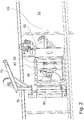
- FIG. 1 shows a portion of a container 20, which is designed according to an embodiment of the invention.
- the container 20 is present in particular a fermenter for a biogas plant. It is roofed to retain generated biogas and discharged for use, which is not shown in the figures.
- the container 20 has a container wall 22.
- the container 20 has an agitator 30 inside.
- the agitator 30 is formed of a motor 32 and a propeller 34. It serves to mix a biomass substrate located in the container 20 and thus to ensure improved production of biogas. For example, solidified areas can be resolved.
- the agitator 30 is attached to a stirrer mount 40, which in turn is attached to the container wall 20.
- the agitator mount 40 is essentially designed as a vertical mast 42.
- the agitator is mounted on the mast 42 vertically, mounted on a carriage, movable, which makes it possible on different heights in the container 20 to use the stirring action of the agitator 30.
- the mast 42 is formed as shown rotatable about its vertical axis, which makes it possible to adjust the direction in which the stirring action is to take place.
- a drivable ring gear 44 is provided.
- a lateral access opening 50 is formed in the container wall 22 . This serves to remove the agitator 30 for maintenance purposes. For this purpose, in particular, the procedure described below or the corresponding method can be used.
- the inspection opening 50 can be closed by means of a flap 52, so that lateral escape of generated biogas is avoided during normal operation.
- the agitator 30 can be moved along the mast 42 into a position in which the agitator 30 is located directly horizontally adjacent to the inspection opening 50. This corresponds to the in FIG. 1 illustrated state.
- the agitator can be fixed in this state with a stop pin 36.
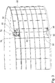
- FIG. 2 shows an outside view of the container 20.
- the agitator 30 and the agitator support 40 can be partially recognized by the open inspection opening 50.
- a gallows bracket 60 is attached outside of the container wall 20.
- a gallows 70 is attached to the top of a crossbar 72 is formed.
- the gallows 70 is pivotable about a vertical axis, which is also defined by the gallows bracket 60. This can be used to remove the agitator 30 from the container 20 in an advantageous manner.
- FIG. 3 shows an external view of the container 20 after removal of the agitator 30.
- the agitator 30 depends on a horizontal traverse 90.
- the horizontal traverse 90 is in turn attached to a cable 80, which in turn depends on the crossbar 72 of the gallows 70.
- the horizontal traverse 90 is rotatable about a horizontal axis defined by the suspension point on the cable 80. As shown, the agitator 30 is spaced from this suspension point. In order to keep the horizontal traverse 90 in balance, opposite to the agitator 30, a counterweight 95 is attached. This is in the form of a tank, which can be filled with water as fiber and in the present case also filled. In this case, just enough water was filled in the counterweight 95 that the horizontal traverse 90 is in equilibrium.
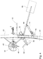
- FIG. 4 shows a state before removing the agitator 30 from the container 20.
- the agitator 30 is attached to the horizontal traverse 90.
- the counterweight 95 is attached opposite to the horizontal traverse 95.
- the counterweight 95 is filled with water until the horizontal traverse 90 is in a torque-free state. This can be determined for example by force measurements or by observing.
- the agitator can be removed from the agitator holder 40.
- the gallows 70 can then be pivoted outwardly about its vertical axis of rotation, so that the agitator 30 is removed from the container 20.
- the flap 52 can then be closed.
- the horizontal traverse 90 can then be lowered, for example, whereby, for example, the in FIG. 3 shown state can be achieved.
- a staple-like stopper 45 may be attached, which prevents an adjustment of the agitator 30 too close to the container wall 22.
- an unlocking bolt can advantageously be provided, by which the further adjustment for removing the agitator can then be made possible.
- the stopper 45 is arranged in a position which does not correspond to the normal operation, but serves for the removal of the agitator.
- the invention comprises: A container, in particular fermenter for a biogas plant, which has a container wall which encloses the container laterally and the container has an agitator, which has a motor and a propeller connected thereto, and the fermenter has a Rlickwerkshalterung, which is adapted to To carry agitator and spend at different positions within the container, wherein in the container wall a closable access opening is formed, through which the agitator can be removed, and the Agitator bracket is adapted to spend the agitator in a position horizontally adjacent to the inspection opening.
- the above-mentioned container, wherein the counterweight is a container which is filled or fillable with dietary fiber, in particular with water.
- the lifting device is attached to a gallows, wherein the gallows on an outside or on the inside of the container wall adjacent to the inspection opening attached gallows bracket is attached, at least partially over the inspection opening lying crossbar and is pivotable about a vertical axis.
- the above method comprising a step of attaching a counterweight to an end of a horizontal traverse of the elevator.
- the above-mentioned use which is carried out using a gallows, wherein the gallows on a outside or inside of the container wall adjacent to the inspection opening attached gallows bracket is attached, has an at least partially over the inspection opening transverse bar and is pivotable about a vertical axis.
Landscapes
- Chemical & Material Sciences (AREA)
- Health & Medical Sciences (AREA)
- Life Sciences & Earth Sciences (AREA)
- Engineering & Computer Science (AREA)
- Bioinformatics & Cheminformatics (AREA)
- Wood Science & Technology (AREA)
- Zoology (AREA)
- Organic Chemistry (AREA)
- Genetics & Genomics (AREA)
- Biotechnology (AREA)
- General Health & Medical Sciences (AREA)
- Biomedical Technology (AREA)
- Sustainable Development (AREA)
- Microbiology (AREA)
- Biochemistry (AREA)
- General Engineering & Computer Science (AREA)
- Molecular Biology (AREA)
- Oil, Petroleum & Natural Gas (AREA)
- General Chemical & Material Sciences (AREA)
- Chemical Kinetics & Catalysis (AREA)
- Medicinal Chemistry (AREA)
- Clinical Laboratory Science (AREA)
- Apparatus Associated With Microorganisms And Enzymes (AREA)
- Mixers Of The Rotary Stirring Type (AREA)
- Processing Of Solid Wastes (AREA)
- Fertilizers (AREA)
Claims (15)
- Récipient, en particulier un fermenteur, destiné à une centrale de biogaz, comportant une paroi de récipient (22) enfermant latéralement le récipient (20), un mélangeur (30) muni d'un moteur (32) et d'une hélice (34) liée à ce moteur, un support de mélangeur (40) réalisé de façon à pouvoir maintenir le mélangeur (30) et de le déplacer au niveau de différentes positions à l'intérieur du récipient (20), et une trappe de révision (50) située dans la paroi de récipient (22) et pouvant être fermée et permettant de retirer le mélangeur (30), de façon à ce que la configuration du support de mélangeur (40) permet de déplacer le mélangeur (30) en une position horizontale à côté de la trappe de révision (50), caractérisé en ce qu'une fixation de potence (60) pour une potence est située à l'intérieur ou à l'extérieur sur la paroi de récipient (22) à côté de la trappe de révision (50) de façon à ce que la potence (70) fixée par la fixation de potence (60) comporte une traverse (72) située au moins partiellement au-dessus de la trappe de révision (50) et à ce que la potence (70) peut pivoter autour d'un axe vertical.
- Récipient selon la revendication 1, caractérisé en ce que le support de fixation (40) est configuré de façon à ce que le mélangeur peut être enlevé de la fixation de mélangeur (40) à proximité de la trappe de révision (50).
- Récipient selon une des revendication précédentes, caractérisé en ce que le support de mélangeur (40) est configuré comme un mât vertical ou incliné le long duquel le mélangeur (30) peut coulisser.
- Récipient selon une des revendications précédentes, caractérisé en ce que la potence (70) supporte un dispositif de levage, en particulier une traverse horizontale (90), partiellement traversant la trappe de révision (50) vers l'intérieur du récipient afin de pouvoir fixer le mélangeur (30) situé à l'intérieur du récipient (20).
- Récipient selon la revendication 4, caractérisé en ce que la traverse horizontale (90) peut être fixée par une de ses extrémités au mélangeur (30) et par l'extrémité opposée à un contre-poids (95) afin d'obtenir essentiellement un équilibre de la traverse horizontale (90).
- Récipient selon la revendication 5, caractérisé en ce que le contre-poids (95) est un récipient rempli ou pouvant être rempli d'un ballaste, en particulier d'eau.
- Procédé d'enlèvement d'un mélangeur d'un récipient latéralement fermé par une paroi de récipient, en particulier un fermenteur, en particulier destiné à une centrale de biogaz, le procédé comportant les étapes suivantes :- déplacement horizontalement du mélangeur au voisinage d'une trappe de révision située dans la paroi de récipient,- ouverture de la trappe de révision,- fixation du mélangeur à un dispositif de levage fixé à une potence qui est maintenue par une fixation de potence située à l'intérieur ou à l'extérieur de la paroi de récipient et à proximité de la trappe de révision et comportant une traverse située au moins partiellement au-dessus de la trappe de révision et pouvant pivoter autour d'un axe vertical,- et l'enlèvement du mélangeur du récipient à l'aide du dispositif de levage.
- Procédé selon la revendication 7, caractérisé en ce que le récipient est configuré selon une des revendications 1 à 6.
- Procédé selon une des revendications 7 ou 8, caractérisé en ce que le mélangeur est enlevé par pivotement de la potence autour de l'axe vertical.
- Procédé selon une des revendications 7 à 9, caractérisé à ce que le dispositif de levage est configuré comme une traverse horizontale.
- Procédé selon une des revendications 7 à 10, caractérisé en ce que le dispositif de levage est fixé à la traverse.
- Procédé selon une des revendications 7 à 11, caractérisé en ce que le mélangeur situé à l'intérieur du récipient est maintenu de façon amovible par une fixation de mélangeur et peut ainsi être désolidarisé de sa fixation avant son enlèvement.
- Utilisation d'une trappe de révision située dans une paroi de récipient latérale, en particulier d'un fermenteur, en particulier d'une centrale à biogaz, destinée à permettre l'enlèvement d'un mélangeur situé à l'intérieur du récipient en utilisant une potence, qui est maintenue par une fixation de potence fixée à l'intérieur ou à l'extérieur de la paroi de récipient à proximité de la trappe de révision, possédant une traverse située au moins partiellement au-dessus de la trappe de révision et pouvant pivoter autour d'un axe vertical.
- Utilisation selon la revendication 13, caractérisé en ce que le récipient est configuré selon une des revendications 1 à 6.
- Utilisation selon une des revendications 13 ou 14, caractérisé en ce que l'enlèvement s'effectue selon une direction horizontale.
Applications Claiming Priority (1)
| Application Number | Priority Date | Filing Date | Title |
|---|---|---|---|
| DE102015121108.4A DE102015121108B4 (de) | 2015-12-03 | 2015-12-03 | Behälter mit Revisionsöffnung |
Publications (2)
| Publication Number | Publication Date |
|---|---|
| EP3176251A1 EP3176251A1 (fr) | 2017-06-07 |
| EP3176251B1 true EP3176251B1 (fr) | 2019-11-20 |
Family
ID=57569871
Family Applications (1)
| Application Number | Title | Priority Date | Filing Date |
|---|---|---|---|
| EP16202052.3A Active EP3176251B1 (fr) | 2015-12-03 | 2016-12-02 | Récipient doté d'une trappe d'inspection |
Country Status (3)
| Country | Link |
|---|---|
| US (1) | US10479970B2 (fr) |
| EP (1) | EP3176251B1 (fr) |
| DE (1) | DE102015121108B4 (fr) |
Families Citing this family (4)
| Publication number | Priority date | Publication date | Assignee | Title |
|---|---|---|---|---|
| EP3604493A1 (fr) * | 2018-08-03 | 2020-02-05 | Thürwächter GmbH & Co. KG | Dispositif de fermeture pour récipients de fermentation |
| IT201900024490A1 (it) | 2019-12-18 | 2021-06-18 | Ies Biogas S R L | Assieme di produzione di biogas o biometano con dispositivo di rilevamento posizione agitatore |
| IT201900024487A1 (it) | 2019-12-18 | 2021-06-18 | Ies Biogas S R L | Assieme di produzione di biogas o biometano |
| DE102023130174A1 (de) * | 2023-10-31 | 2025-04-30 | Michael Niederbacher | Biogasanlagen-Fermenterbehälter sowie Verfahren zum Betrieb |
Family Cites Families (10)
| Publication number | Priority date | Publication date | Assignee | Title |
|---|---|---|---|---|
| DE3345643A1 (de) * | 1983-12-16 | 1985-06-27 | Moser, Barbara, 8152 Feldkirchen-Westerham | Vorrichtung zum aufbereiten von vorzugsweise in behaeltern befindlichen fluessigkeiten, insbesondere von guelle |
| DE4015478C1 (fr) * | 1990-05-14 | 1991-09-12 | Abs Pumpen Ag, 5204 Lohmar, De | |
| DE10010672C2 (de) * | 2000-03-04 | 2002-11-21 | Uts Umwelt Technik Sued Gmbh | Biogasanlage zur Fermentation von organischen Stoffen |
| DE202004011561U1 (de) | 2004-07-24 | 2004-10-14 | U.T.S. Umwelt-Technik-Süd GmbH | Biogasanlage zur Fermentation von organischen Stoffen |
| DE102007009451B4 (de) * | 2007-02-27 | 2010-04-01 | Uts Biogastechnik Gmbh | Biogasanlagen-Fermenter mit einem motorisch höhenverstellbaren Tauchmotorrührgerät |
| DE102007012014B4 (de) | 2007-03-13 | 2010-08-05 | Uts Biogastechnik Gmbh | Verfahren zum Ein- und Ausbau eines Rührgeräts in eine Biogasanlage und Tragarmverlängerung zur Durchführung des Verfahrens |
| DE102009034127A1 (de) * | 2009-01-21 | 2010-07-22 | Uts Biogastechnik Gmbh | Biogasanlagen-Serviceeinrichtung |
| DE102009041569B4 (de) | 2009-09-15 | 2015-05-21 | Sbbiogas Gmbh | Anlage zur Erzeugung von Biogas |
| EP2513285B1 (fr) * | 2009-12-16 | 2014-10-29 | MT-Energie GmbH | Récipient d'une installation de biogaz et procédé pour prélever un composant du récipient |
| DE102012021206A1 (de) * | 2012-10-30 | 2014-04-30 | Uts Biogastechnik Gmbh | Fermenter einer Biogasanlage |
-
2015
- 2015-12-03 DE DE102015121108.4A patent/DE102015121108B4/de not_active Expired - Fee Related
-
2016
- 2016-12-02 EP EP16202052.3A patent/EP3176251B1/fr active Active
- 2016-12-02 US US15/368,067 patent/US10479970B2/en active Active
Non-Patent Citations (1)
| Title |
|---|
| None * |
Also Published As
| Publication number | Publication date |
|---|---|
| DE102015121108A1 (de) | 2017-06-08 |
| US20170211024A1 (en) | 2017-07-27 |
| US10479970B2 (en) | 2019-11-19 |
| EP3176251A1 (fr) | 2017-06-07 |
| DE102015121108B4 (de) | 2019-05-09 |
Similar Documents
| Publication | Publication Date | Title |
|---|---|---|
| EP3176251B1 (fr) | Récipient doté d'une trappe d'inspection | |
| DE102015008610B3 (de) | Transportvorrichtung für lang gestreckte Hebegüter | |
| WO2014015948A2 (fr) | Installation à biogaz | |
| DE102009031177A1 (de) | Biogasanlage und Serviceeinrichtung für eine Biogasanlage | |
| DE3512467C1 (de) | Fernbedient auswechselbares Einbauteil | |
| EP3556458B1 (fr) | Agitateur immergé | |
| DE19501414A1 (de) | Vorrichtung zum Handhaben von untergetaucht arbeitenden Aggregaten | |
| DE102016010913B4 (de) | System zum Handling von Gitterstücken | |
| DE10203017B4 (de) | Allzweck-Deckelheber für Kanal- und Schachtdeckel | |
| DE1812859A1 (de) | Anordnung fuer einen senkrecht stehenden,unterirdisch anzuordnenden Lagertank fuer Fluessigkeiten und Schuettgut,insbesondere fuer Kraftstoffe | |
| DE202011101434U1 (de) | Kompakt-Greiferlaufkatze | |
| EP0318633A2 (fr) | Récipient à ordures | |
| DE2305425C2 (de) | Vorrichtung zum Errichten von Kranmasten | |
| DE202013006152U1 (de) | Ruhrstahl-Heraeus-Anlage | |
| DE202016103063U1 (de) | Vorrichtung zur Entleerung eines Industriesaugers | |
| DE927979C (de) | Hochsilo fuer kleinstueckigen Inhalt | |
| DE4224631A1 (de) | Arbeitsbühne für die Verwendung in Türmen, Kaminen, Schächten oder dergleichen und Verfahren zur Verwendung solcher Arbeitsbühnen | |
| EP2910496A1 (fr) | Dispositif de transport ou de stockage de produits en vrac, procédé de chargement du dispositif et véhicule comprenant un tel dispositif | |
| DE19540945A1 (de) | Flächenbelüfter mit Hebevorrichtung | |
| DE3324110C1 (de) | Betonkübel mit Standplatz | |
| DE3625674C1 (en) | Device for transporting and depositing plants arranged in pots or the like | |
| DE102018124609A1 (de) | Schließvorrichtung für Fermentierbehälter | |
| DE2931421A1 (de) | Auslegerturmkran | |
| DE2302823C3 (de) | Bootsanhänger | |
| DE548088C (de) | Fuetterungseinrichtung fuer Grossviehstallungen mit in der Hoehe verstellbaren Futterraufen |
Legal Events
| Date | Code | Title | Description |
|---|---|---|---|
| AK | Designated contracting states |
Kind code of ref document: A1 Designated state(s): AL AT BE BG CH CY CZ DE DK EE ES FI FR GB GR HR HU IE IS IT LI LT LU LV MC MK MT NL NO PL PT RO RS SE SI SK SM TR |
|
| AX | Request for extension of the european patent |
Extension state: BA ME |
|
| PUAI | Public reference made under article 153(3) epc to a published international application that has entered the european phase |
Free format text: ORIGINAL CODE: 0009012 |
|
| STAA | Information on the status of an ep patent application or granted ep patent |
Free format text: STATUS: THE APPLICATION HAS BEEN PUBLISHED |
|
| STAA | Information on the status of an ep patent application or granted ep patent |
Free format text: STATUS: REQUEST FOR EXAMINATION WAS MADE |
|
| 17P | Request for examination filed |
Effective date: 20171206 |
|
| RBV | Designated contracting states (corrected) |
Designated state(s): AL AT BE BG CH CY CZ DE DK EE ES FI FR GB GR HR HU IE IS IT LI LT LU LV MC MK MT NL NO PL PT RO RS SE SI SK SM TR |
|
| GRAP | Despatch of communication of intention to grant a patent |
Free format text: ORIGINAL CODE: EPIDOSNIGR1 |
|
| STAA | Information on the status of an ep patent application or granted ep patent |
Free format text: STATUS: GRANT OF PATENT IS INTENDED |
|
| RIC1 | Information provided on ipc code assigned before grant |
Ipc: C12M 1/06 20060101ALI20190524BHEP Ipc: C12M 1/107 20060101AFI20190524BHEP |
|
| INTG | Intention to grant announced |
Effective date: 20190618 |
|
| GRAS | Grant fee paid |
Free format text: ORIGINAL CODE: EPIDOSNIGR3 |
|
| GRAA | (expected) grant |
Free format text: ORIGINAL CODE: 0009210 |
|
| STAA | Information on the status of an ep patent application or granted ep patent |
Free format text: STATUS: THE PATENT HAS BEEN GRANTED |
|
| AK | Designated contracting states |
Kind code of ref document: B1 Designated state(s): AL AT BE BG CH CY CZ DE DK EE ES FI FR GB GR HR HU IE IS IT LI LT LU LV MC MK MT NL NO PL PT RO RS SE SI SK SM TR |
|
| REG | Reference to a national code |
Ref country code: GB Ref legal event code: FG4D Free format text: NOT ENGLISH |
|
| REG | Reference to a national code |
Ref country code: CH Ref legal event code: EP |
|
| REG | Reference to a national code |
Ref country code: DE Ref legal event code: R096 Ref document number: 502016007624 Country of ref document: DE |
|
| REG | Reference to a national code |
Ref country code: IE Ref legal event code: FG4D Free format text: LANGUAGE OF EP DOCUMENT: GERMAN |
|
| REG | Reference to a national code |
Ref country code: AT Ref legal event code: REF Ref document number: 1204210 Country of ref document: AT Kind code of ref document: T Effective date: 20191215 |
|
| REG | Reference to a national code |
Ref country code: NL Ref legal event code: MP Effective date: 20191120 |
|
| REG | Reference to a national code |
Ref country code: LT Ref legal event code: MG4D |
|
| PG25 | Lapsed in a contracting state [announced via postgrant information from national office to epo] |
Ref country code: BG Free format text: LAPSE BECAUSE OF FAILURE TO SUBMIT A TRANSLATION OF THE DESCRIPTION OR TO PAY THE FEE WITHIN THE PRESCRIBED TIME-LIMIT Effective date: 20200220 Ref country code: FI Free format text: LAPSE BECAUSE OF FAILURE TO SUBMIT A TRANSLATION OF THE DESCRIPTION OR TO PAY THE FEE WITHIN THE PRESCRIBED TIME-LIMIT Effective date: 20191120 Ref country code: NL Free format text: LAPSE BECAUSE OF FAILURE TO SUBMIT A TRANSLATION OF THE DESCRIPTION OR TO PAY THE FEE WITHIN THE PRESCRIBED TIME-LIMIT Effective date: 20191120 Ref country code: SE Free format text: LAPSE BECAUSE OF FAILURE TO SUBMIT A TRANSLATION OF THE DESCRIPTION OR TO PAY THE FEE WITHIN THE PRESCRIBED TIME-LIMIT Effective date: 20191120 Ref country code: LV Free format text: LAPSE BECAUSE OF FAILURE TO SUBMIT A TRANSLATION OF THE DESCRIPTION OR TO PAY THE FEE WITHIN THE PRESCRIBED TIME-LIMIT Effective date: 20191120 Ref country code: LT Free format text: LAPSE BECAUSE OF FAILURE TO SUBMIT A TRANSLATION OF THE DESCRIPTION OR TO PAY THE FEE WITHIN THE PRESCRIBED TIME-LIMIT Effective date: 20191120 Ref country code: NO Free format text: LAPSE BECAUSE OF FAILURE TO SUBMIT A TRANSLATION OF THE DESCRIPTION OR TO PAY THE FEE WITHIN THE PRESCRIBED TIME-LIMIT Effective date: 20200220 Ref country code: GR Free format text: LAPSE BECAUSE OF FAILURE TO SUBMIT A TRANSLATION OF THE DESCRIPTION OR TO PAY THE FEE WITHIN THE PRESCRIBED TIME-LIMIT Effective date: 20200221 |
|
| PG25 | Lapsed in a contracting state [announced via postgrant information from national office to epo] |
Ref country code: IS Free format text: LAPSE BECAUSE OF FAILURE TO SUBMIT A TRANSLATION OF THE DESCRIPTION OR TO PAY THE FEE WITHIN THE PRESCRIBED TIME-LIMIT Effective date: 20200320 Ref country code: HR Free format text: LAPSE BECAUSE OF FAILURE TO SUBMIT A TRANSLATION OF THE DESCRIPTION OR TO PAY THE FEE WITHIN THE PRESCRIBED TIME-LIMIT Effective date: 20191120 Ref country code: RS Free format text: LAPSE BECAUSE OF FAILURE TO SUBMIT A TRANSLATION OF THE DESCRIPTION OR TO PAY THE FEE WITHIN THE PRESCRIBED TIME-LIMIT Effective date: 20191120 |
|
| PG25 | Lapsed in a contracting state [announced via postgrant information from national office to epo] |
Ref country code: AL Free format text: LAPSE BECAUSE OF FAILURE TO SUBMIT A TRANSLATION OF THE DESCRIPTION OR TO PAY THE FEE WITHIN THE PRESCRIBED TIME-LIMIT Effective date: 20191120 |
|
| REG | Reference to a national code |
Ref country code: DE Ref legal event code: R082 Ref document number: 502016007624 Country of ref document: DE Representative=s name: STUMPF PATENTANWAELTE PARTGMBB, DE |
|
| REG | Reference to a national code |
Ref country code: DE Ref legal event code: R082 Ref document number: 502016007624 Country of ref document: DE Representative=s name: STUMPF PATENTANWAELTE PARTGMBB, DE |
|
| PG25 | Lapsed in a contracting state [announced via postgrant information from national office to epo] |
Ref country code: EE Free format text: LAPSE BECAUSE OF FAILURE TO SUBMIT A TRANSLATION OF THE DESCRIPTION OR TO PAY THE FEE WITHIN THE PRESCRIBED TIME-LIMIT Effective date: 20191120 Ref country code: PT Free format text: LAPSE BECAUSE OF FAILURE TO SUBMIT A TRANSLATION OF THE DESCRIPTION OR TO PAY THE FEE WITHIN THE PRESCRIBED TIME-LIMIT Effective date: 20200412 Ref country code: CZ Free format text: LAPSE BECAUSE OF FAILURE TO SUBMIT A TRANSLATION OF THE DESCRIPTION OR TO PAY THE FEE WITHIN THE PRESCRIBED TIME-LIMIT Effective date: 20191120 Ref country code: RO Free format text: LAPSE BECAUSE OF FAILURE TO SUBMIT A TRANSLATION OF THE DESCRIPTION OR TO PAY THE FEE WITHIN THE PRESCRIBED TIME-LIMIT Effective date: 20191120 Ref country code: DK Free format text: LAPSE BECAUSE OF FAILURE TO SUBMIT A TRANSLATION OF THE DESCRIPTION OR TO PAY THE FEE WITHIN THE PRESCRIBED TIME-LIMIT Effective date: 20191120 |
|
| REG | Reference to a national code |
Ref country code: CH Ref legal event code: PL |
|
| REG | Reference to a national code |
Ref country code: DE Ref legal event code: R097 Ref document number: 502016007624 Country of ref document: DE |
|
| REG | Reference to a national code |
Ref country code: BE Ref legal event code: MM Effective date: 20191231 |
|
| PG25 | Lapsed in a contracting state [announced via postgrant information from national office to epo] |
Ref country code: MC Free format text: LAPSE BECAUSE OF FAILURE TO SUBMIT A TRANSLATION OF THE DESCRIPTION OR TO PAY THE FEE WITHIN THE PRESCRIBED TIME-LIMIT Effective date: 20191120 Ref country code: SK Free format text: LAPSE BECAUSE OF FAILURE TO SUBMIT A TRANSLATION OF THE DESCRIPTION OR TO PAY THE FEE WITHIN THE PRESCRIBED TIME-LIMIT Effective date: 20191120 Ref country code: SM Free format text: LAPSE BECAUSE OF FAILURE TO SUBMIT A TRANSLATION OF THE DESCRIPTION OR TO PAY THE FEE WITHIN THE PRESCRIBED TIME-LIMIT Effective date: 20191120 |
|
| PLBE | No opposition filed within time limit |
Free format text: ORIGINAL CODE: 0009261 |
|
| STAA | Information on the status of an ep patent application or granted ep patent |
Free format text: STATUS: NO OPPOSITION FILED WITHIN TIME LIMIT |
|
| 26N | No opposition filed |
Effective date: 20200821 |
|
| PG25 | Lapsed in a contracting state [announced via postgrant information from national office to epo] |
Ref country code: LU Free format text: LAPSE BECAUSE OF NON-PAYMENT OF DUE FEES Effective date: 20191202 Ref country code: ES Free format text: LAPSE BECAUSE OF FAILURE TO SUBMIT A TRANSLATION OF THE DESCRIPTION OR TO PAY THE FEE WITHIN THE PRESCRIBED TIME-LIMIT Effective date: 20191120 Ref country code: IE Free format text: LAPSE BECAUSE OF NON-PAYMENT OF DUE FEES Effective date: 20191202 |
|
| PG25 | Lapsed in a contracting state [announced via postgrant information from national office to epo] |
Ref country code: BE Free format text: LAPSE BECAUSE OF NON-PAYMENT OF DUE FEES Effective date: 20191231 Ref country code: SI Free format text: LAPSE BECAUSE OF FAILURE TO SUBMIT A TRANSLATION OF THE DESCRIPTION OR TO PAY THE FEE WITHIN THE PRESCRIBED TIME-LIMIT Effective date: 20191120 Ref country code: CH Free format text: LAPSE BECAUSE OF NON-PAYMENT OF DUE FEES Effective date: 20191231 Ref country code: LI Free format text: LAPSE BECAUSE OF NON-PAYMENT OF DUE FEES Effective date: 20191231 Ref country code: PL Free format text: LAPSE BECAUSE OF FAILURE TO SUBMIT A TRANSLATION OF THE DESCRIPTION OR TO PAY THE FEE WITHIN THE PRESCRIBED TIME-LIMIT Effective date: 20191120 |
|
| PG25 | Lapsed in a contracting state [announced via postgrant information from national office to epo] |
Ref country code: CY Free format text: LAPSE BECAUSE OF FAILURE TO SUBMIT A TRANSLATION OF THE DESCRIPTION OR TO PAY THE FEE WITHIN THE PRESCRIBED TIME-LIMIT Effective date: 20191120 |
|
| PG25 | Lapsed in a contracting state [announced via postgrant information from national office to epo] |
Ref country code: HU Free format text: LAPSE BECAUSE OF FAILURE TO SUBMIT A TRANSLATION OF THE DESCRIPTION OR TO PAY THE FEE WITHIN THE PRESCRIBED TIME-LIMIT; INVALID AB INITIO Effective date: 20161202 Ref country code: MT Free format text: LAPSE BECAUSE OF FAILURE TO SUBMIT A TRANSLATION OF THE DESCRIPTION OR TO PAY THE FEE WITHIN THE PRESCRIBED TIME-LIMIT Effective date: 20191120 |
|
| GBPC | Gb: european patent ceased through non-payment of renewal fee |
Effective date: 20201202 |
|
| PG25 | Lapsed in a contracting state [announced via postgrant information from national office to epo] |
Ref country code: GB Free format text: LAPSE BECAUSE OF NON-PAYMENT OF DUE FEES Effective date: 20201202 |
|
| PG25 | Lapsed in a contracting state [announced via postgrant information from national office to epo] |
Ref country code: TR Free format text: LAPSE BECAUSE OF FAILURE TO SUBMIT A TRANSLATION OF THE DESCRIPTION OR TO PAY THE FEE WITHIN THE PRESCRIBED TIME-LIMIT Effective date: 20191120 |
|
| PG25 | Lapsed in a contracting state [announced via postgrant information from national office to epo] |
Ref country code: MK Free format text: LAPSE BECAUSE OF FAILURE TO SUBMIT A TRANSLATION OF THE DESCRIPTION OR TO PAY THE FEE WITHIN THE PRESCRIBED TIME-LIMIT Effective date: 20191120 |
|
| REG | Reference to a national code |
Ref country code: AT Ref legal event code: MM01 Ref document number: 1204210 Country of ref document: AT Kind code of ref document: T Effective date: 20211202 |
|
| PG25 | Lapsed in a contracting state [announced via postgrant information from national office to epo] |
Ref country code: AT Free format text: LAPSE BECAUSE OF NON-PAYMENT OF DUE FEES Effective date: 20211202 |
|
| PGFP | Annual fee paid to national office [announced via postgrant information from national office to epo] |
Ref country code: DE Payment date: 20251127 Year of fee payment: 10 |
|
| PGFP | Annual fee paid to national office [announced via postgrant information from national office to epo] |
Ref country code: FR Payment date: 20251218 Year of fee payment: 10 |
|
| PGFP | Annual fee paid to national office [announced via postgrant information from national office to epo] |
Ref country code: IT Payment date: 20251231 Year of fee payment: 10 |