EP3604493A1 - Dispositif de fermeture pour récipients de fermentation - Google Patents
Dispositif de fermeture pour récipients de fermentation Download PDFInfo
- Publication number
- EP3604493A1 EP3604493A1 EP19188925.2A EP19188925A EP3604493A1 EP 3604493 A1 EP3604493 A1 EP 3604493A1 EP 19188925 A EP19188925 A EP 19188925A EP 3604493 A1 EP3604493 A1 EP 3604493A1
- Authority
- EP
- European Patent Office
- Prior art keywords
- partition
- closure element
- opening
- maintenance opening
- cable
- Prior art date
- Legal status (The legal status is an assumption and is not a legal conclusion. Google has not performed a legal analysis and makes no representation as to the accuracy of the status listed.)
- Pending
Links
Images
Classifications
-
- C—CHEMISTRY; METALLURGY
- C12—BIOCHEMISTRY; BEER; SPIRITS; WINE; VINEGAR; MICROBIOLOGY; ENZYMOLOGY; MUTATION OR GENETIC ENGINEERING
- C12M—APPARATUS FOR ENZYMOLOGY OR MICROBIOLOGY; APPARATUS FOR CULTURING MICROORGANISMS FOR PRODUCING BIOMASS, FOR GROWING CELLS OR FOR OBTAINING FERMENTATION OR METABOLIC PRODUCTS, i.e. BIOREACTORS OR FERMENTERS
- C12M21/00—Bioreactors or fermenters specially adapted for specific uses
- C12M21/04—Bioreactors or fermenters specially adapted for specific uses for producing gas, e.g. biogas
-
- C—CHEMISTRY; METALLURGY
- C12—BIOCHEMISTRY; BEER; SPIRITS; WINE; VINEGAR; MICROBIOLOGY; ENZYMOLOGY; MUTATION OR GENETIC ENGINEERING
- C12M—APPARATUS FOR ENZYMOLOGY OR MICROBIOLOGY; APPARATUS FOR CULTURING MICROORGANISMS FOR PRODUCING BIOMASS, FOR GROWING CELLS OR FOR OBTAINING FERMENTATION OR METABOLIC PRODUCTS, i.e. BIOREACTORS OR FERMENTERS
- C12M23/00—Constructional details, e.g. recesses, hinges
- C12M23/26—Constructional details, e.g. recesses, hinges flexible
-
- C—CHEMISTRY; METALLURGY
- C12—BIOCHEMISTRY; BEER; SPIRITS; WINE; VINEGAR; MICROBIOLOGY; ENZYMOLOGY; MUTATION OR GENETIC ENGINEERING
- C12M—APPARATUS FOR ENZYMOLOGY OR MICROBIOLOGY; APPARATUS FOR CULTURING MICROORGANISMS FOR PRODUCING BIOMASS, FOR GROWING CELLS OR FOR OBTAINING FERMENTATION OR METABOLIC PRODUCTS, i.e. BIOREACTORS OR FERMENTERS
- C12M23/00—Constructional details, e.g. recesses, hinges
- C12M23/36—Means for collection or storage of gas; Gas holders
-
- C—CHEMISTRY; METALLURGY
- C12—BIOCHEMISTRY; BEER; SPIRITS; WINE; VINEGAR; MICROBIOLOGY; ENZYMOLOGY; MUTATION OR GENETIC ENGINEERING
- C12M—APPARATUS FOR ENZYMOLOGY OR MICROBIOLOGY; APPARATUS FOR CULTURING MICROORGANISMS FOR PRODUCING BIOMASS, FOR GROWING CELLS OR FOR OBTAINING FERMENTATION OR METABOLIC PRODUCTS, i.e. BIOREACTORS OR FERMENTERS
- C12M27/00—Means for mixing, agitating or circulating fluids in the vessel
- C12M27/02—Stirrer or mobile mixing elements
-
- Y—GENERAL TAGGING OF NEW TECHNOLOGICAL DEVELOPMENTS; GENERAL TAGGING OF CROSS-SECTIONAL TECHNOLOGIES SPANNING OVER SEVERAL SECTIONS OF THE IPC; TECHNICAL SUBJECTS COVERED BY FORMER USPC CROSS-REFERENCE ART COLLECTIONS [XRACs] AND DIGESTS
- Y02—TECHNOLOGIES OR APPLICATIONS FOR MITIGATION OR ADAPTATION AGAINST CLIMATE CHANGE
- Y02E—REDUCTION OF GREENHOUSE GAS [GHG] EMISSIONS, RELATED TO ENERGY GENERATION, TRANSMISSION OR DISTRIBUTION
- Y02E50/00—Technologies for the production of fuel of non-fossil origin
- Y02E50/30—Fuel from waste, e.g. synthetic alcohol or diesel
Definitions
- the invention relates to a device for opening and closing a maintenance opening provided in a top wall of a fermentation container, with a body for connecting the device to a maintenance opening of a fermentation container and a closure element for optionally opening and closing the maintenance opening.
- the invention further relates to a biogas plant and a method for opening and closing a maintenance opening provided in a top wall of a fermentation container.
- fermentation tanks serve to supply a predominantly liquid substrate arranged in the fermentation tank ferment.
- the substrate can contain excrement from livestock and vegetable waste, for example.
- a biogas formed during the fermentation of the substrate rises from the substrate and accumulates in a volume of the fermentation container above a liquid level of the substrate.
- a fluid line is provided which is fluidly connected to the volume of the fermentation container containing the biogas.
- the biogas obtained in this way can be used, for example, to drive a vehicle or to generate electrical energy.
- biogas plants usually include stirring units with propellers.
- the propellers are arranged in the substrate below the liquid level and can rotate and mix the substrate continuously or at intervals in time by rotating, thereby counteracting the fermentation-causing inhomogeneities of the substrate, in particular the formation of layers in the substrate.
- stirring unit which is also referred to as an agitator
- a maintenance opening is therefore provided in a top wall of the fermentation container and a column extending through the maintenance opening is provided in the fermentation container, on which column the stirring unit is held displaceably by means of a linear guide.
- the stirring unit can be moved along the column to an outside of the fermentation tank, where it is easily accessible for specialist personnel.
- the maintenance opening is closed by an appropriate device so that the biogas cannot escape through the maintenance opening in an uncontrolled manner.
- the maintenance opening In order to maintain or repair the stirring unit, the maintenance opening must be opened so that the biogas escapes unused through the maintenance opening.
- biogas that has already been formed is lost in this way, and on the other hand, the biogas that is formed is highly flammable, which is associated with a corresponding risk of fire and explosion outside the fermentation tank. Apart from that, the biogas pollutes the environment like a propellant.
- the invention relates to a device for opening and closing a maintenance opening provided in a top wall of a fermentation container, having a body for connecting the device to a maintenance opening of a fermentation container and a closure element for optionally opening and closing the maintenance opening.
- the invention proposes a device which allows the maintenance opening to be opened and closed with a closure element.
- the device comprises a partition wall for separating a volume below the maintenance opening and an actuating mechanism for selectively lowering and raising the partition wall between a raised rest position and a lowered separation position.
- the partition is accordingly designed to selectively separate a volume inside the fermentation container. To do this, it is from a rest position in which it does not separate any volume, into a separation position in which it separates the volume, can be lowered or raised from the separation position to the rest position.
- a locking mechanism is provided on the device, in particular on the body, for locking and unlocking the closure element in a closed position of the closure element.
- the locking mechanism can ensure that the closure element is not inadvertently moved out of its closed position. Moving the locked closure element is excluded. Only the unlocked locking element can be moved out of the closed position.
- the locking mechanism is designed such that the closure element can only be locked and / or unlocked in the lowered, separated position of the partition.
- the locking mechanism cannot be operated when the partition is in a position other than the lowered separation position. This makes incorrect operation impossible and significantly improves work safety on the device.
- the partition is designed for the gas-tight connection of a liquid level arranged in the interior of the fermentation container to the body. Accordingly, the partition can be lowered in such a way that it is immersed in a predominantly liquid substrate present in the fermentation container.
- the locking mechanism comprises a passage provided on the body, a passage provided on the closure element, which are aligned with one another in the closed position of the closure element, and a shaft, the shaft penetrating the two passages in a locked state of the locking mechanism and is pulled out of the two passages in an unlocked state of the locking mechanism.
- the shaft acts as a bolt which is inserted through the two passages for locking and is removed from these for unlocking.
- the locking mechanism comprises a cable drum attached to the shaft and a cable connected to the cable drum.
- the rope can be used to apply a force to the shaft in order to fix the shaft in the two passages and to prevent unlocking.
- the shaft in the locked state the shaft carries a section of the cable provided for lowering and raising the partition.
- the section provided for moving the partition wall can be rolled up in the cable drum. If the partition is not in its separation position, the rope is tensioned and the weight of the partition is loaded on the shaft. If, on the other hand, the partition is in its separation position, the rope is relaxed and the weight is not applied to the shaft. Because of this, the shaft can only be pulled out of the passages in the disconnected position, which is why it is only possible to unlock the closure element in the disconnected position.
- the actuating mechanism is designed and arranged in such a way that the partition can be actuated on a side of the body opposite the partition is. Such an actuation mechanism allows the partition to be actuated comfortably outside the fermentation container.
- the actuating mechanism comprises the shaft rotatably mounted in the two passages and the cable drum rotatably connected to the shaft for the optional winding and unwinding of the cable.
- the rope drum and the rope thus have a dual function. They not only act within the locking mechanism, but can also be used to move the partition.
- a first free end of the rope is connected to the rope drum and a second free end of the rope is connected to a free end region of the partition. Accordingly, the rope is essentially completely unrolled from the rope drum in the separating position of the dividing wall and essentially rolled up in the rope drum when the dividing wall is in the rest position.
- the actuating mechanism and / or the locking mechanism comprises two cable drums which are arranged at opposite free ends of the shaft and two cables which are connected to opposite free end regions of the partition.
- a force can be applied to the partition wall symmetrically by means of two ropes, thereby reducing the risk of the partition wall tilting during lowering or lifting.
- the actuating mechanism has a drive unit for rotatingly driving the shaft.
- the drive unit allows the shaft to be turned more easily.
- the drive unit advantageously comprises a crank that can be detachably connected to the cable drum, in particular a braked one Ratchet crank.
- the crank forms a drive unit that is particularly easy to handle for manually moving the partition. It can be connected in a rotationally fixed manner to move the partition wall and can be detached from the shaft after moving the partition wall.
- a braked, ie unidirectionally locking ratchet crank can reduce the force required to wind up the rope.
- the actuating mechanism for a comprises a deflection roller rotatably mounted on the body for guiding the rope. Thanks to the deflection roller, the flexibility in guiding the rope is increased.
- each rope extends through a rope opening provided in the body.
- the rope opening is a simple means of guiding the rope from the side of the body opposite the partition to the side of the body facing the partition.
- the partition can advantageously comprise a plastic or consist of a plastic.
- plastics are available and are easy to handle during manufacture.
- the partition wall can comprise a woven fabric or consist of a woven fabric. Fabrics can be easily bendable and have high tensile strength.
- the partition comprises a tubular apron.
- the tubular shape In the separating position of the dividing wall, the tubular shape encloses a relatively small volume that is fluidly connected to the maintenance opening and, if appropriate, one that is separated by the volume from the inside of the fermentation container through the maintenance opening extending column.
- a biogas present in this volume enclosed by the partition wall can escape uncontrolled through the maintenance opening in the open position of the closure element.
- the relatively larger volume on the outside of the partition is separated from the maintenance opening in a gas-tight manner, so that the biogas arranged there cannot escape uncontrolled through the maintenance opening and therefore remains in the fermentation container during maintenance or repair of the stirring unit.
- the apron or the partition wall is advantageously designed to be accordion-like foldable. This makes it easier to lower and raise the partition, and the partition requires little space in the rest position.
- the partition wall comprises a rigid frame, which is arranged in particular at a free end region of the partition wall and is connected to it.
- the frame stabilizes the partition and defines a cross-sectional area of the partition according to its shape.
- the frame is arranged on an end region facing the body and / or on an end region of the partition facing away from the body. With this arrangement, the frame ensures a substantially constant cross-sectional area in the separating position of the dividing wall over the entire length of the dividing wall.
- the partition can comprise several wall elements.
- the length of the partition wall formed from several wall elements can also be changed by moving the wall elements in order to move them between the rest position and the separation position.
- the wall elements can be designed and arranged to be telescopically displaceable relative to one another. In this way, a proven and simple length variability of the partition can be created.
- the partition is preferably attached to the body.
- the attachment to the body prevents biogas from escaping uncontrollably between the body and the partition.
- the body supports the partition in the disconnected position, relieving the rope and unlocking the end element.
- the partition wall has a probe, in particular for detecting an electrical resistance.
- the electrical resistance of a path inside the substrate is lower than the electrical resistance of the same path outside the substrate, i.e. within the biogas arranged above the liquid level of the substrate. Therefore, the vertical position of the liquid level can be determined by measuring the electrical resistance.
- other probes that are able to detect the presence of the liquid level are also suitable, e.g. capacitive or optical sensors.
- the probe is arranged on an end region of the partition facing away from the body and / or is rod-shaped and in particular extends away from the body. In other words, it can be determined in this way whether the partition extends to the substrate or is immersed in the substrate, that is to say bridges the entire distance between the maintenance opening and the liquid level. If a further probe of this type is additionally attached to the stirring unit, it can be provided in terms of circuitry that the stirring unit can only be operated if the stirring unit is below the liquid level and the free end of the Partition is arranged above the liquid level. As a result of this spatial separation of the stirring unit and the partition wall, it is ensured that the partition wall is not damaged by the stirring unit itself or by the substrate moved by it during the operation of the stirring unit.
- the closure element comprises a plate. Plates are easy to manufacture and handle.
- the closure element can comprise a plate made of a metal.
- the plate advantageously has two plate sections, which in particular extend perpendicular to one another and / or are connected to one another at a common edge. With such a plate complex opening areas can be closed.
- a plate section laterally closes a box-shaped structure of the body.
- the box-shaped structure can at least partially house a component of the biogas plant arranged outside the maintenance opening.
- the closure element has an elongated reinforcement profile which is detachably connected, in particular screwed, to a plate section.
- the reinforcement profile serves for the stable fastening of the closure element.
- the closure element advantageously has two or more than two reinforcement profiles, which in particular extend parallel to one another and / or in each case parallel to the plate section. This further improves the stability of the fastening.
- the closure element is arranged on the device such that it can be removed or rotatably mounted. In other words, the closure element can be detached from the device or rotated relative to the device.
- the closure element can be detachably connected to the body or held pivotably on the body between the closed position and an open position of the closure element. In the open position, the closure element is thus removed from the body or pivoted relative to the body.
- the device can be skillfully inserted into the maintenance opening.
- An outer contour of the device corresponds to an inner contour of the maintenance opening.
- the body comprises a closed frame that can be connected, in particular screwed, to an edge region of the maintenance opening.
- the frame forms a transition area surrounding the maintenance opening between the device and the fermentation container.
- the frame advantageously has a circumferential first contact surface which, when the device is installed as intended, lies against the edge region of the maintenance opening.
- the contact surface ensures that the device connects gastight to the edge area of the maintenance opening.
- the frame also has a circumferential second contact surface against which the closure element bears in the closed position of the closure element.
- the second contact surface ensures that the closure element lies gas-tight on the body of the device.
- the frame has a plurality of flat connecting struts, which in particular extend perpendicularly between the first contact surface and the second contact surface and / or have a trapezoidal outer contour.
- the connecting struts reinforce the frame and reduce deformation of the frame under the action of force.
- the invention also relates to a biogas plant comprising a fermentation tank with a maintenance opening formed in a top wall of the fermentation tank.
- a biogas plant comprising a fermentation tank with a maintenance opening formed in a top wall of the fermentation tank.
- the biogas plant comprises a device according to the invention and / or a device which is operated in a method according to the invention.
- the biogas plant is thus protected from the outside from an uncontrolled escape of a predominant amount of a biogas present in the fermentation tank.
- the biogas plant includes a stirring unit.
- the stirring unit serves to homogenize an essentially liquid substrate arranged in the biogas plant and therefore counteracts undesired formation of layers in the substrate.
- Another object of the invention is a method for opening a closure element for a fermentation tank of a biogas plant according to the invention, wherein the closure element is only opened when the partition is lowered.
- the closure element is only opened when the partition is lowered.
- the closure element is only opened when the device is connected in a gastight manner to the liquid level in the interior of the fermentation container through the partition. In this position of the partition, a volume inside the fermentation container is separated from the maintenance opening in a gastight manner.
- Another object of the present invention is a method for closing a closure element for a fermentation tank of a biogas plant according to the invention, wherein the closure element is closed before the partition is raised.
- the closed closure element prevents a biogas which is present in the fermentation container and which is freely movable as a result of the lifting of the partition wall from uncontrolled escape through the maintenance opening to the outside.
- the partition is only raised from the liquid level when the closure element is closed. In other words, it is impossible for the maintenance opening to be opened after the partition is raised from the liquid level.
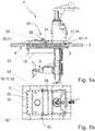
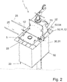
- the Figures 1a, 1b and 2 show a device 1 for opening and closing a maintenance opening 3 provided in a top wall 2 of a fermentation tank of a biogas plant from different viewing directions and in different states.
- the biogas plant comprises a stirring unit 6, which is held by means of a linear guide on a column 5 which extends through the maintenance opening 3.
- a cable pull with a drive unit 53 arranged outside the fermentation container can be provided.
- the device 1 can be inserted into the maintenance opening 3 and comprises a body 10 for connecting the device 1 to the maintenance opening 3 of the fermentation container and a closure element 20 for optionally opening and closing the maintenance opening 3.
- the body 10 comprises a closed frame 11 which can be screwed to an edge region 4 of the maintenance opening 3.
- the frame 11 has a circumferential first contact surface 12 which, when the device 1 is installed as intended, bears against the edge region 4 of the maintenance opening 3.
- the frame 11 has a circumferential second contact surface 13, against which the closure element 20 bears in a closed position of the closure element 20.
- the frame 11 also has a plurality of flat connecting struts 14 which, spaced apart from one another and distributed along the circumference of the frame 11, each extend perpendicularly between the first contact surface 12 and the second contact surface 13 and have a trapezoidal outer contour.
- the device 1 comprises a maintenance flap 16 which is pivotably held on the frame. It is only accessible when the maintenance opening 3 is open and allows the maintenance opening 3 to be opened and closed independently of the closure element 20.
- the closure element 20 is removably arranged on the device 1 and detachably connected to the body 10, but can also be rotatably mounted on the body 10 and can be pivoted between a closed position and an open position of the closure element 20.
- the closure element 20 comprises a plate 21 made of a metal, which has two plate sections 22, 23 which extend perpendicular to one another and are connected to one another at a common edge 24. In the closed position of the closure element 20, a plate section 23 laterally closes a box-shaped structure 15 of the body 10.
- the closure element 20 has two elongate reinforcement profiles 25 which can be screwed to a plate section 22 and which, when screwed as intended, extend parallel to one another and parallel to the plate section 22.
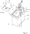
- the device 1 comprises a partition 30 for separating a volume below the maintenance opening 3 and an actuating mechanism for optionally lowering and raising the partition 30 between one Figure 1a shown raised rest position and one in the Figures 2 and 3 lowered position shown.
- the partition wall 30 is fastened to the body 10 and is designed for the gas-tight connection of a liquid level arranged in the interior of the fermentation container to the body 10 and comprises a tubular apron 31. It consists of a fabric made of plastic, but can also be made of another material his. Furthermore, the tubular apron 31 is designed to be foldable like an accordion, but can also comprise a plurality of wall elements which are designed to be telescopically displaceable relative to one another.
- the partition wall 30 further comprises a rigid frame 32 which is arranged on a free end region of the partition wall 30 facing away from the body 10 and is connected to the latter.
- the partition 30 also has a probe 33 for detecting an electrical resistance.
- the probe 33 is arranged on an end region of the partition 30 facing away from the body 10, is rod-shaped and extends away from the body 10.
- the device 1 comprises a locking mechanism provided on the body 10 for locking and unlocking the closure element 20 in a closed position of the closure element 20.
- the locking mechanism is designed in such a way that the closure element 20 can only be locked and / or unlocked in the lowered, separated position of the partition 30.
- the locking mechanism comprises a passage provided on the body 10, two passages provided on the closure element 20, all of which are flush with one another in the closed position of the closure element 20, and a shaft 56.
- the shaft 56 extends through the passages in a locked state of the locking mechanism and is pulled out of the passages in an unlocked state of the locking mechanism.
- the locking mechanism comprises two cable drums 52 and two cables 51, each connected to a cable drum 52.
- the cable drums 52 can be connected to the shaft 56, so that the shaft 56 in the locked state carries a section of each cable 51 provided for lowering and lifting the partition 30.
- the device 1 further comprises an actuating mechanism 50.
- the actuating mechanism 50 is designed and arranged in such a way that the partition wall 30 is on an opposite side of the partition wall 30 Side of the body 10, that is to say can be actuated on an outside of the fermentation container.
- the actuating mechanism 50 comprises the shaft 56, which is rotatably mounted in the two passages, and the cable drums 52, which are arranged at opposite free ends of the shaft 56 and are each non-rotatably connected to the shaft 56, for the optional winding and unwinding of the cables 51 with a cable drum 52 and a second free end of each cable 51 connected to a free end region of the partition 30 and attached to opposite sides of the frame 32.
- the actuating mechanism 50 has a drive unit 53 for rotatingly driving the shaft 56, which comprises a crank 54 in the form of a braked ratchet crank which can be releasably connected to a cable drum 52.
- the actuation mechanism 50 further comprises a deflection roller 55 which is rotatably mounted on the body 10 for guiding the cable 51 and which extends from an outside of the device 1 to an inside of the device 1 through a cable opening provided in the body 10.
- closure element 20 When the closure element 20 is actuated, the closure element 20 is only opened when the partition 30 is lowered, ie when the device 1 is connected in a gastight manner to the liquid level in the interior of the fermentation container through the partition 30. As in Figure 2 shown, a cable drum 52 is released from the shaft 56 and the shaft 56 is laterally pulled out of the passages in order to unlock the closure element 20. In addition, the two reinforcement profiles 25 are loosened and removed. The closure element 20 is then released from the device 1 and moved from the closed position into an open position, as in FIG Figure 3 is shown.
- the closure element 20 is closed before the partition 30 is lifted, i.e. the partition 30 is only raised from the liquid level when the closure element 20 is closed.
- An essential advantage of the device 1 according to the invention is that the partition reliably prevents an uncontrolled escape of a predominant portion of the biogas present in the fermentation tank to the outside.
- the device can also use a locking mechanism to ensure that the maintenance opening is only closed or released when the partition is lowered.
- the invention includes:
- a device for opening and closing a maintenance opening provided in a top wall of a fermentation container with a body for connecting the device to a maintenance opening of a fermentation container and a closure element for optionally opening and closing the maintenance opening, a partition for separating a volume below the maintenance opening and an actuating mechanism to selectively lower and raise the Partition between a raised rest position and a lowered separation position.
- a device according to the invention for opening and closing a maintenance opening provided in a top wall of a fermentation container, comprising a locking mechanism provided on the device, in particular on the body, for locking and unlocking the closure element in a closed position of the closure element.
- a device according to the invention for opening and closing a maintenance opening provided in a top wall of a fermentation container, the locking mechanism being designed such that the closure element can be locked and / or unlocked only in the lowered separation position of the partition.
- a device for opening and closing a maintenance opening provided in a top wall of a fermentation container as explained above, wherein the locking mechanism has a passage provided on the body and one on the closure element Passage, which are aligned with each other in the closed position of the closure element, and comprises a shaft, wherein the shaft extends through the two passages in a locked state of the locking mechanism and is pulled out of the two passages in an unlocked state of the locking mechanism.
- a device for opening and closing a maintenance opening provided in a top wall of a fermentation container as explained above, wherein the locking mechanism comprises a cable drum and a cable connected to the cable drum.
- a device for opening and closing a maintenance opening provided in a top wall of a fermentation container as explained above, the shaft in the locked state carrying a section of the cable provided for lowering and raising the partition.
- a device for opening and closing of a maintenance opening provided in a top wall of a fermentation container comprising the shaft rotatably mounted in the two passages and the cable drum rotatably connected to the shaft for optionally winding and unrolling the cable.
- a device for opening and closing a maintenance opening provided in a top wall of a fermentation container wherein a first free end of the cable connects with the Rope drum and a second free end of the rope are connected to a free end region of the partition.
- a device for opening and closing a maintenance opening provided in a top wall of a fermentation container comprising a crank which can be detachably connected to the cable drum, in particular a braked ratchet crank.
- a device for opening and closing a maintenance opening provided in a top wall of a fermentation container as previously explained, the partition wall comprising a tubular apron.
- a device for opening and closing a maintenance opening provided in a top wall of a fermentation container as previously explained, the partition wall or the apron being designed to be accordion-like foldable.
- a device for opening and closing a maintenance opening provided in a top wall of a fermentation container comprising a rigid frame which is arranged in particular at a free end region of the partition wall and is connected to the latter.
- a device for opening and closing a maintenance opening provided in a top wall of a fermentation container as previously explained, the frame being arranged on an end region facing the body and / or on an end region facing away from the body of the partition.
- a device for opening and closing a maintenance opening provided in a top wall of a fermentation container as explained above, the partition wall comprising a plurality of wall elements.
- a device for opening and closing a maintenance opening provided in a top wall of a fermentation container as explained above, the wall elements being designed and arranged to be telescopically displaceable relative to one another.
- a device for opening and closing a maintenance opening provided in a top wall of a fermentation container as explained above, wherein the probe is arranged on an end region of the partition facing away from the body and / or is rod-shaped and in particular extends away from the body.
- a device for opening and closing a maintenance opening provided in a top wall of a fermentation container as explained above, wherein the plate has two plate sections, which in particular extend perpendicular to one another and / or are connected to one another at a common edge.
- a device for opening and closing of a maintenance opening provided in a top wall of a fermentation container as explained above, wherein in a closed position of the closure element a plate section laterally closes a box-shaped structure of the body.
- a device for opening and closing a maintenance opening provided in a top wall of a fermentation container wherein the closure element has two or more than two reinforcement profiles, which extend in particular parallel to one another and / or in each case parallel to the plate section.
- a device for opening and closing a maintenance opening provided in a top wall of a fermentation container, the closure element being arranged on the device such that it can be removed or rotatably mounted.
- a device for opening and closing a maintenance opening provided in a top wall of a fermentation container as explained above, wherein the closure element is detachably connected to the body or is pivotably held on the body between a closed position and an open position of the closure element.
- a device for opening and closing as provided above provided in a top wall of a fermentation container Maintenance opening, the device being insertable into the maintenance opening.
- a device for opening and closing a maintenance opening provided in a top wall of a fermentation container as explained above, wherein the body comprises a closed frame which can be connected, in particular screwed, to an edge region of the maintenance opening.
- a device for opening and closing of a maintenance opening provided in a top wall of a fermentation container as explained above, wherein the frame has a circumferential first contact surface which, when the device is installed as intended, lies against the edge region of the maintenance opening.
- a device for opening and closing a maintenance opening provided in a top wall of a fermentation container as previously explained, the frame having a circumferential second contact surface against which the closure element bears in a closed position of the closure element.
- a device for opening and closing a maintenance opening provided in a top wall of a fermentation container wherein the frame has a plurality of flat connecting struts, which in particular extend perpendicularly between the first contact surface and the second contact surface and / or have a trapezoidal outer contour.
- the invention further comprises:
- a biogas plant comprising a fermentation tank with a maintenance opening formed in a top wall of the fermentation tank and a device according to the invention and / or a device that is operated in a method according to the invention.
- a biogas plant comprising a device according to the invention and / or a device which is operated in a method according to the invention.
- the invention also includes:
- a method for opening a closure element for a fermentation tank of a biogas plant according to the invention wherein the closure element is only opened when the partition is lowered.
- the invention further comprises:
- a method for closing a closure element for a fermentation tank of a biogas plant according to the invention wherein the closure element is closed before the partition is raised.
Landscapes
- Health & Medical Sciences (AREA)
- Life Sciences & Earth Sciences (AREA)
- Chemical & Material Sciences (AREA)
- Engineering & Computer Science (AREA)
- Organic Chemistry (AREA)
- Zoology (AREA)
- Bioinformatics & Cheminformatics (AREA)
- Wood Science & Technology (AREA)
- Genetics & Genomics (AREA)
- General Health & Medical Sciences (AREA)
- Biomedical Technology (AREA)
- Biochemistry (AREA)
- General Engineering & Computer Science (AREA)
- Biotechnology (AREA)
- Sustainable Development (AREA)
- Microbiology (AREA)
- Clinical Laboratory Science (AREA)
- Molecular Biology (AREA)
- General Chemical & Material Sciences (AREA)
- Oil, Petroleum & Natural Gas (AREA)
- Apparatus Associated With Microorganisms And Enzymes (AREA)
Applications Claiming Priority (2)
| Application Number | Priority Date | Filing Date | Title |
|---|---|---|---|
| DE102018118870 | 2018-08-03 | ||
| DE102018124609.9A DE102018124609A1 (de) | 2018-08-03 | 2018-10-05 | Schließvorrichtung für Fermentierbehälter |
Publications (1)
| Publication Number | Publication Date |
|---|---|
| EP3604493A1 true EP3604493A1 (fr) | 2020-02-05 |
Family
ID=67539202
Family Applications (1)
| Application Number | Title | Priority Date | Filing Date |
|---|---|---|---|
| EP19188925.2A Pending EP3604493A1 (fr) | 2018-08-03 | 2019-07-29 | Dispositif de fermeture pour récipients de fermentation |
Country Status (1)
| Country | Link |
|---|---|
| EP (1) | EP3604493A1 (fr) |
Citations (7)
| Publication number | Priority date | Publication date | Assignee | Title |
|---|---|---|---|---|
| DE19714342C1 (de) * | 1997-04-08 | 1998-10-01 | Uts Umwelt Technik Sued Gmbh | Biogasanlage zur Fermentation von organischen Stoffen |
| EP1717305A1 (fr) * | 2005-04-25 | 2006-11-02 | U.T.S. Umwelt-Technik-Süd GmbH | Élement de regard pour le fermenteur d'une installation de biogaz |
| EP2174704A1 (fr) * | 2008-10-07 | 2010-04-14 | Rajib Pal Chowdhury | Dispositif de mise à disposition pour l'entretien d'un appareil de plongée entraîné et réglable en hauteur sur un récipient de fermentation d'installations de biogaz |
| EP2270128A1 (fr) * | 2009-06-29 | 2011-01-05 | Uts Biogastechnik Gmbh | Installation de biogaz et élement de regard pour une installation de biogaz |
| EP2497822A1 (fr) * | 2011-03-08 | 2012-09-12 | Michael Dr. Niederbacher | Récipient de fermentation d'installations de biogaz doté d'un dispositif d'entretien |
| WO2013071444A1 (fr) * | 2011-11-17 | 2013-05-23 | Anaergia Inc. | Dispositif d'entretien de fermenteur anaérobie muni d'un rideau de séparation |
| DE102015121108A1 (de) * | 2015-12-03 | 2017-06-08 | Thürwächter GmbH & Co. KG | Behälter mit Revisionsöffnung |
-
2019
- 2019-07-29 EP EP19188925.2A patent/EP3604493A1/fr active Pending
Patent Citations (7)
| Publication number | Priority date | Publication date | Assignee | Title |
|---|---|---|---|---|
| DE19714342C1 (de) * | 1997-04-08 | 1998-10-01 | Uts Umwelt Technik Sued Gmbh | Biogasanlage zur Fermentation von organischen Stoffen |
| EP1717305A1 (fr) * | 2005-04-25 | 2006-11-02 | U.T.S. Umwelt-Technik-Süd GmbH | Élement de regard pour le fermenteur d'une installation de biogaz |
| EP2174704A1 (fr) * | 2008-10-07 | 2010-04-14 | Rajib Pal Chowdhury | Dispositif de mise à disposition pour l'entretien d'un appareil de plongée entraîné et réglable en hauteur sur un récipient de fermentation d'installations de biogaz |
| EP2270128A1 (fr) * | 2009-06-29 | 2011-01-05 | Uts Biogastechnik Gmbh | Installation de biogaz et élement de regard pour une installation de biogaz |
| EP2497822A1 (fr) * | 2011-03-08 | 2012-09-12 | Michael Dr. Niederbacher | Récipient de fermentation d'installations de biogaz doté d'un dispositif d'entretien |
| WO2013071444A1 (fr) * | 2011-11-17 | 2013-05-23 | Anaergia Inc. | Dispositif d'entretien de fermenteur anaérobie muni d'un rideau de séparation |
| DE102015121108A1 (de) * | 2015-12-03 | 2017-06-08 | Thürwächter GmbH & Co. KG | Behälter mit Revisionsöffnung |
Similar Documents
| Publication | Publication Date | Title |
|---|---|---|
| WO2014015948A2 (fr) | Installation à biogaz | |
| DE202009010167U1 (de) | Hub- und Schwenkvorrichtung für ein höhenverstellbares angetriebenes Tauchgerät an einem Fermenterbehälter einer Biogasanlage | |
| CH712759A2 (de) | Aufblasbares Sportgerät, vorzugsweise für den Wassersport. | |
| EP3176251B1 (fr) | Récipient doté d'une trappe d'inspection | |
| DE112010001118B4 (de) | Fester Open-Top-Container | |
| DE102018124609A1 (de) | Schließvorrichtung für Fermentierbehälter | |
| DE3403824A1 (de) | Sammelbehaelter fuer wiederverwendbares sammelgut | |
| DE2736116C2 (de) | Zentrifugalpumpe | |
| EP3604493A1 (fr) | Dispositif de fermeture pour récipients de fermentation | |
| DE3608730C2 (fr) | ||
| DE3032277C2 (de) | Schwimmbecken mit einer rolladenartigen, auf einer Welle aufwickelbaren schwimmfähigen Abdeckung | |
| EP0261339B1 (fr) | Combinaison d'une flèche et transmission d'un treuil pour treuils à crémaillère d'un dispositif de soulèvement et de pose pour grands récipients de transport ou similaires | |
| DE29720711U1 (de) | Luftfahrzeug für den Gütertransport | |
| DE1684044C3 (de) | Fahrzeug mit Behältern zur Aufnahme von Betonkomponenten | |
| DE4017544A1 (de) | Behaelter mit bodenklappe | |
| AT308344B (de) | Aufrollbare Abdeckung für mit Flüssigkeit gefüllte Becken, insbesondere für Schwimmbecken | |
| DE19540945A1 (de) | Flächenbelüfter mit Hebevorrichtung | |
| CH702820A2 (de) | Aushängegelenk sowie Schachtabdeckung. | |
| DE3324110C1 (de) | Betonkübel mit Standplatz | |
| DE2548574A1 (de) | Hubboden fuer badebecken | |
| EP4335984A1 (fr) | Siphon et toilettes de séparation dotées d'un siphon | |
| DE3521811A1 (de) | Vorrichtung zum befuellen eines fluessigkeitsbehaelters | |
| DE1908289A1 (de) | Muellkasten fuer den Transport radioaktiver Abfaelle | |
| DE202008005901U1 (de) | Hubvorrichtung für eine Tragfläche | |
| CH212139A (de) | Jaucherührer. |
Legal Events
| Date | Code | Title | Description |
|---|---|---|---|
| PUAI | Public reference made under article 153(3) epc to a published international application that has entered the european phase |
Free format text: ORIGINAL CODE: 0009012 |
|
| STAA | Information on the status of an ep patent application or granted ep patent |
Free format text: STATUS: THE APPLICATION HAS BEEN PUBLISHED |
|
| AK | Designated contracting states |
Kind code of ref document: A1 Designated state(s): AL AT BE BG CH CY CZ DE DK EE ES FI FR GB GR HR HU IE IS IT LI LT LU LV MC MK MT NL NO PL PT RO RS SE SI SK SM TR |
|
| AX | Request for extension of the european patent |
Extension state: BA ME |
|
| STAA | Information on the status of an ep patent application or granted ep patent |
Free format text: STATUS: REQUEST FOR EXAMINATION WAS MADE |
|
| 17P | Request for examination filed |
Effective date: 20200805 |
|
| RAV | Requested validation state of the european patent: fee paid |
Extension state: MA Effective date: 20200805 Extension state: TN Effective date: 20200805 Extension state: KH Effective date: 20200805 Extension state: MD Effective date: 20200805 |
|
| RAX | Requested extension states of the european patent have changed |
Extension state: BA Payment date: 20200805 Extension state: ME Payment date: 20200805 |
|
| RBV | Designated contracting states (corrected) |
Designated state(s): AL AT BE BG CH CY CZ DE DK EE ES FI FR GB GR HR HU IE IS IT LI LT LU LV MC MK MT NL NO PL PT RO RS SE SI SK SM TR |
|
| STAA | Information on the status of an ep patent application or granted ep patent |
Free format text: STATUS: EXAMINATION IS IN PROGRESS |
|
| 17Q | First examination report despatched |
Effective date: 20250922 |
|
| STAA | Information on the status of an ep patent application or granted ep patent |
Free format text: STATUS: THE APPLICATION IS DEEMED TO BE WITHDRAWN |