EP3176479A1 - Distributeur à tiroir cylindrique - Google Patents
Distributeur à tiroir cylindrique Download PDFInfo
- Publication number
- EP3176479A1 EP3176479A1 EP15826598.3A EP15826598A EP3176479A1 EP 3176479 A1 EP3176479 A1 EP 3176479A1 EP 15826598 A EP15826598 A EP 15826598A EP 3176479 A1 EP3176479 A1 EP 3176479A1
- Authority
- EP
- European Patent Office
- Prior art keywords
- spool
- electric motor
- ball
- screw
- nut
- Prior art date
- Legal status (The legal status is an assumption and is not a legal conclusion. Google has not performed a legal analysis and makes no representation as to the accuracy of the status listed.)
- Granted
Links
- 238000003780 insertion Methods 0.000 claims abstract description 17
- 230000037431 insertion Effects 0.000 claims abstract description 17
- 230000007246 mechanism Effects 0.000 claims description 26
- 230000006835 compression Effects 0.000 claims description 8
- 238000007906 compression Methods 0.000 claims description 8
- 230000005540 biological transmission Effects 0.000 abstract description 16
- 230000004043 responsiveness Effects 0.000 abstract description 5
- 239000003921 oil Substances 0.000 description 27
- 230000004323 axial length Effects 0.000 description 7
- 230000007935 neutral effect Effects 0.000 description 6
- 238000005096 rolling process Methods 0.000 description 4
- 239000012530 fluid Substances 0.000 description 1
- 239000010720 hydraulic oil Substances 0.000 description 1
- 238000002347 injection Methods 0.000 description 1
- 239000007924 injection Substances 0.000 description 1
- 230000000717 retained effect Effects 0.000 description 1
Images





Classifications
-
- F—MECHANICAL ENGINEERING; LIGHTING; HEATING; WEAPONS; BLASTING
- F16—ENGINEERING ELEMENTS AND UNITS; GENERAL MEASURES FOR PRODUCING AND MAINTAINING EFFECTIVE FUNCTIONING OF MACHINES OR INSTALLATIONS; THERMAL INSULATION IN GENERAL
- F16H—GEARING
- F16H63/00—Control outputs from the control unit to change-speed- or reversing-gearings for conveying rotary motion or to other devices than the final output mechanism
- F16H63/02—Final output mechanisms therefor; Actuating means for the final output mechanisms
- F16H63/04—Final output mechanisms therefor; Actuating means for the final output mechanisms a single final output mechanism being moved by a single final actuating mechanism
- F16H63/06—Final output mechanisms therefor; Actuating means for the final output mechanisms a single final output mechanism being moved by a single final actuating mechanism the final output mechanism having an indefinite number of positions
- F16H63/062—Final output mechanisms therefor; Actuating means for the final output mechanisms a single final output mechanism being moved by a single final actuating mechanism the final output mechanism having an indefinite number of positions electric or electro-mechanical actuating means
-
- F—MECHANICAL ENGINEERING; LIGHTING; HEATING; WEAPONS; BLASTING
- F16—ENGINEERING ELEMENTS AND UNITS; GENERAL MEASURES FOR PRODUCING AND MAINTAINING EFFECTIVE FUNCTIONING OF MACHINES OR INSTALLATIONS; THERMAL INSULATION IN GENERAL
- F16H—GEARING
- F16H61/00—Control functions within control units of change-speed- or reversing-gearings for conveying rotary motion ; Control of exclusively fluid gearing, friction gearing, gearings with endless flexible members or other particular types of gearing
- F16H61/66—Control functions within control units of change-speed- or reversing-gearings for conveying rotary motion ; Control of exclusively fluid gearing, friction gearing, gearings with endless flexible members or other particular types of gearing specially adapted for continuously variable gearings
- F16H61/662—Control functions within control units of change-speed- or reversing-gearings for conveying rotary motion ; Control of exclusively fluid gearing, friction gearing, gearings with endless flexible members or other particular types of gearing specially adapted for continuously variable gearings with endless flexible members
- F16H61/66254—Control functions within control units of change-speed- or reversing-gearings for conveying rotary motion ; Control of exclusively fluid gearing, friction gearing, gearings with endless flexible members or other particular types of gearing specially adapted for continuously variable gearings with endless flexible members controlling of shifting being influenced by a signal derived from the engine and the main coupling
- F16H61/66259—Control functions within control units of change-speed- or reversing-gearings for conveying rotary motion ; Control of exclusively fluid gearing, friction gearing, gearings with endless flexible members or other particular types of gearing specially adapted for continuously variable gearings with endless flexible members controlling of shifting being influenced by a signal derived from the engine and the main coupling using electrical or electronical sensing or control means
-
- B—PERFORMING OPERATIONS; TRANSPORTING
- B60—VEHICLES IN GENERAL
- B60W—CONJOINT CONTROL OF VEHICLE SUB-UNITS OF DIFFERENT TYPE OR DIFFERENT FUNCTION; CONTROL SYSTEMS SPECIALLY ADAPTED FOR HYBRID VEHICLES; ROAD VEHICLE DRIVE CONTROL SYSTEMS FOR PURPOSES NOT RELATED TO THE CONTROL OF A PARTICULAR SUB-UNIT
- B60W10/00—Conjoint control of vehicle sub-units of different type or different function
- B60W10/04—Conjoint control of vehicle sub-units of different type or different function including control of propulsion units
-
- B—PERFORMING OPERATIONS; TRANSPORTING
- B60—VEHICLES IN GENERAL
- B60W—CONJOINT CONTROL OF VEHICLE SUB-UNITS OF DIFFERENT TYPE OR DIFFERENT FUNCTION; CONTROL SYSTEMS SPECIALLY ADAPTED FOR HYBRID VEHICLES; ROAD VEHICLE DRIVE CONTROL SYSTEMS FOR PURPOSES NOT RELATED TO THE CONTROL OF A PARTICULAR SUB-UNIT
- B60W10/00—Conjoint control of vehicle sub-units of different type or different function
- B60W10/10—Conjoint control of vehicle sub-units of different type or different function including control of change-speed gearings
- B60W10/101—Infinitely variable gearings
-
- F—MECHANICAL ENGINEERING; LIGHTING; HEATING; WEAPONS; BLASTING
- F15—FLUID-PRESSURE ACTUATORS; HYDRAULICS OR PNEUMATICS IN GENERAL
- F15B—SYSTEMS ACTING BY MEANS OF FLUIDS IN GENERAL; FLUID-PRESSURE ACTUATORS, e.g. SERVOMOTORS; DETAILS OF FLUID-PRESSURE SYSTEMS, NOT OTHERWISE PROVIDED FOR
- F15B13/00—Details of servomotor systems ; Valves for servomotor systems
- F15B13/02—Fluid distribution or supply devices characterised by their adaptation to the control of servomotors
- F15B13/04—Fluid distribution or supply devices characterised by their adaptation to the control of servomotors for use with a single servomotor
- F15B13/0401—Valve members; Fluid interconnections therefor
- F15B13/0402—Valve members; Fluid interconnections therefor for linearly sliding valves, e.g. spool valves
-
- F—MECHANICAL ENGINEERING; LIGHTING; HEATING; WEAPONS; BLASTING
- F16—ENGINEERING ELEMENTS AND UNITS; GENERAL MEASURES FOR PRODUCING AND MAINTAINING EFFECTIVE FUNCTIONING OF MACHINES OR INSTALLATIONS; THERMAL INSULATION IN GENERAL
- F16H—GEARING
- F16H61/00—Control functions within control units of change-speed- or reversing-gearings for conveying rotary motion ; Control of exclusively fluid gearing, friction gearing, gearings with endless flexible members or other particular types of gearing
- F16H61/02—Control functions within control units of change-speed- or reversing-gearings for conveying rotary motion ; Control of exclusively fluid gearing, friction gearing, gearings with endless flexible members or other particular types of gearing characterised by the signals used
- F16H61/0202—Control functions within control units of change-speed- or reversing-gearings for conveying rotary motion ; Control of exclusively fluid gearing, friction gearing, gearings with endless flexible members or other particular types of gearing characterised by the signals used the signals being electric
- F16H61/0251—Elements specially adapted for electric control units, e.g. valves for converting electrical signals to fluid signals
-
- F—MECHANICAL ENGINEERING; LIGHTING; HEATING; WEAPONS; BLASTING
- F16—ENGINEERING ELEMENTS AND UNITS; GENERAL MEASURES FOR PRODUCING AND MAINTAINING EFFECTIVE FUNCTIONING OF MACHINES OR INSTALLATIONS; THERMAL INSULATION IN GENERAL
- F16H—GEARING
- F16H63/00—Control outputs from the control unit to change-speed- or reversing-gearings for conveying rotary motion or to other devices than the final output mechanism
- F16H63/02—Final output mechanisms therefor; Actuating means for the final output mechanisms
- F16H63/04—Final output mechanisms therefor; Actuating means for the final output mechanisms a single final output mechanism being moved by a single final actuating mechanism
- F16H63/06—Final output mechanisms therefor; Actuating means for the final output mechanisms a single final output mechanism being moved by a single final actuating mechanism the final output mechanism having an indefinite number of positions
- F16H63/065—Final output mechanisms therefor; Actuating means for the final output mechanisms a single final output mechanism being moved by a single final actuating mechanism the final output mechanism having an indefinite number of positions hydraulic actuating means
-
- F—MECHANICAL ENGINEERING; LIGHTING; HEATING; WEAPONS; BLASTING
- F16—ENGINEERING ELEMENTS AND UNITS; GENERAL MEASURES FOR PRODUCING AND MAINTAINING EFFECTIVE FUNCTIONING OF MACHINES OR INSTALLATIONS; THERMAL INSULATION IN GENERAL
- F16K—VALVES; TAPS; COCKS; ACTUATING-FLOATS; DEVICES FOR VENTING OR AERATING
- F16K11/00—Multiple-way valves, e.g. mixing valves; Pipe fittings incorporating such valves
- F16K11/02—Multiple-way valves, e.g. mixing valves; Pipe fittings incorporating such valves with all movable sealing faces moving as one unit
- F16K11/06—Multiple-way valves, e.g. mixing valves; Pipe fittings incorporating such valves with all movable sealing faces moving as one unit comprising only sliding valves, i.e. sliding closure elements
- F16K11/065—Multiple-way valves, e.g. mixing valves; Pipe fittings incorporating such valves with all movable sealing faces moving as one unit comprising only sliding valves, i.e. sliding closure elements with linearly sliding closure members
-
- F—MECHANICAL ENGINEERING; LIGHTING; HEATING; WEAPONS; BLASTING
- F16—ENGINEERING ELEMENTS AND UNITS; GENERAL MEASURES FOR PRODUCING AND MAINTAINING EFFECTIVE FUNCTIONING OF MACHINES OR INSTALLATIONS; THERMAL INSULATION IN GENERAL
- F16K—VALVES; TAPS; COCKS; ACTUATING-FLOATS; DEVICES FOR VENTING OR AERATING
- F16K11/00—Multiple-way valves, e.g. mixing valves; Pipe fittings incorporating such valves
- F16K11/02—Multiple-way valves, e.g. mixing valves; Pipe fittings incorporating such valves with all movable sealing faces moving as one unit
- F16K11/06—Multiple-way valves, e.g. mixing valves; Pipe fittings incorporating such valves with all movable sealing faces moving as one unit comprising only sliding valves, i.e. sliding closure elements
- F16K11/065—Multiple-way valves, e.g. mixing valves; Pipe fittings incorporating such valves with all movable sealing faces moving as one unit comprising only sliding valves, i.e. sliding closure elements with linearly sliding closure members
- F16K11/07—Multiple-way valves, e.g. mixing valves; Pipe fittings incorporating such valves with all movable sealing faces moving as one unit comprising only sliding valves, i.e. sliding closure elements with linearly sliding closure members with cylindrical slides
-
- F—MECHANICAL ENGINEERING; LIGHTING; HEATING; WEAPONS; BLASTING
- F16—ENGINEERING ELEMENTS AND UNITS; GENERAL MEASURES FOR PRODUCING AND MAINTAINING EFFECTIVE FUNCTIONING OF MACHINES OR INSTALLATIONS; THERMAL INSULATION IN GENERAL
- F16K—VALVES; TAPS; COCKS; ACTUATING-FLOATS; DEVICES FOR VENTING OR AERATING
- F16K31/00—Actuating devices; Operating means; Releasing devices
- F16K31/02—Actuating devices; Operating means; Releasing devices electric; magnetic
- F16K31/04—Actuating devices; Operating means; Releasing devices electric; magnetic using a motor
-
- F—MECHANICAL ENGINEERING; LIGHTING; HEATING; WEAPONS; BLASTING
- F16—ENGINEERING ELEMENTS AND UNITS; GENERAL MEASURES FOR PRODUCING AND MAINTAINING EFFECTIVE FUNCTIONING OF MACHINES OR INSTALLATIONS; THERMAL INSULATION IN GENERAL
- F16K—VALVES; TAPS; COCKS; ACTUATING-FLOATS; DEVICES FOR VENTING OR AERATING
- F16K31/00—Actuating devices; Operating means; Releasing devices
- F16K31/44—Mechanical actuating means
- F16K31/50—Mechanical actuating means with screw-spindle or internally threaded actuating means
-
- F—MECHANICAL ENGINEERING; LIGHTING; HEATING; WEAPONS; BLASTING
- F16—ENGINEERING ELEMENTS AND UNITS; GENERAL MEASURES FOR PRODUCING AND MAINTAINING EFFECTIVE FUNCTIONING OF MACHINES OR INSTALLATIONS; THERMAL INSULATION IN GENERAL
- F16K—VALVES; TAPS; COCKS; ACTUATING-FLOATS; DEVICES FOR VENTING OR AERATING
- F16K31/00—Actuating devices; Operating means; Releasing devices
- F16K31/44—Mechanical actuating means
- F16K31/53—Mechanical actuating means with toothed gearing
-
- F—MECHANICAL ENGINEERING; LIGHTING; HEATING; WEAPONS; BLASTING
- F16—ENGINEERING ELEMENTS AND UNITS; GENERAL MEASURES FOR PRODUCING AND MAINTAINING EFFECTIVE FUNCTIONING OF MACHINES OR INSTALLATIONS; THERMAL INSULATION IN GENERAL
- F16H—GEARING
- F16H25/00—Gearings comprising primarily only cams, cam-followers and screw-and-nut mechanisms
- F16H25/18—Gearings comprising primarily only cams, cam-followers and screw-and-nut mechanisms for conveying or interconverting oscillating or reciprocating motions
- F16H25/20—Screw mechanisms
- F16H2025/204—Axial sliding means, i.e. for rotary support and axial guiding of nut or screw shaft
-
- F—MECHANICAL ENGINEERING; LIGHTING; HEATING; WEAPONS; BLASTING
- F16—ENGINEERING ELEMENTS AND UNITS; GENERAL MEASURES FOR PRODUCING AND MAINTAINING EFFECTIVE FUNCTIONING OF MACHINES OR INSTALLATIONS; THERMAL INSULATION IN GENERAL
- F16H—GEARING
- F16H25/00—Gearings comprising primarily only cams, cam-followers and screw-and-nut mechanisms
- F16H25/18—Gearings comprising primarily only cams, cam-followers and screw-and-nut mechanisms for conveying or interconverting oscillating or reciprocating motions
- F16H25/20—Screw mechanisms
- F16H2025/2062—Arrangements for driving the actuator
- F16H2025/2087—Arrangements for driving the actuator using planetary gears
-
- F—MECHANICAL ENGINEERING; LIGHTING; HEATING; WEAPONS; BLASTING
- F16—ENGINEERING ELEMENTS AND UNITS; GENERAL MEASURES FOR PRODUCING AND MAINTAINING EFFECTIVE FUNCTIONING OF MACHINES OR INSTALLATIONS; THERMAL INSULATION IN GENERAL
- F16H—GEARING
- F16H61/00—Control functions within control units of change-speed- or reversing-gearings for conveying rotary motion ; Control of exclusively fluid gearing, friction gearing, gearings with endless flexible members or other particular types of gearing
- F16H61/02—Control functions within control units of change-speed- or reversing-gearings for conveying rotary motion ; Control of exclusively fluid gearing, friction gearing, gearings with endless flexible members or other particular types of gearing characterised by the signals used
- F16H61/0202—Control functions within control units of change-speed- or reversing-gearings for conveying rotary motion ; Control of exclusively fluid gearing, friction gearing, gearings with endless flexible members or other particular types of gearing characterised by the signals used the signals being electric
- F16H61/0251—Elements specially adapted for electric control units, e.g. valves for converting electrical signals to fluid signals
- F16H2061/0253—Details of electro hydraulic valves, e.g. lands, ports, spools or springs
-
- F—MECHANICAL ENGINEERING; LIGHTING; HEATING; WEAPONS; BLASTING
- F16—ENGINEERING ELEMENTS AND UNITS; GENERAL MEASURES FOR PRODUCING AND MAINTAINING EFFECTIVE FUNCTIONING OF MACHINES OR INSTALLATIONS; THERMAL INSULATION IN GENERAL
- F16H—GEARING
- F16H63/00—Control outputs from the control unit to change-speed- or reversing-gearings for conveying rotary motion or to other devices than the final output mechanism
- F16H63/02—Final output mechanisms therefor; Actuating means for the final output mechanisms
- F16H63/30—Constructional features of the final output mechanisms
- F16H63/304—Constructional features of the final output mechanisms the final output mechanisms comprising elements moved by electrical or magnetic force
- F16H2063/3063—Constructional features of the final output mechanisms the final output mechanisms comprising elements moved by electrical or magnetic force using screw devices
-
- F—MECHANICAL ENGINEERING; LIGHTING; HEATING; WEAPONS; BLASTING
- F16—ENGINEERING ELEMENTS AND UNITS; GENERAL MEASURES FOR PRODUCING AND MAINTAINING EFFECTIVE FUNCTIONING OF MACHINES OR INSTALLATIONS; THERMAL INSULATION IN GENERAL
- F16H—GEARING
- F16H25/00—Gearings comprising primarily only cams, cam-followers and screw-and-nut mechanisms
- F16H25/18—Gearings comprising primarily only cams, cam-followers and screw-and-nut mechanisms for conveying or interconverting oscillating or reciprocating motions
- F16H25/20—Screw mechanisms
- F16H25/22—Screw mechanisms with balls, rollers, or similar members between the co-operating parts; Elements essential to the use of such members
- F16H25/2204—Screw mechanisms with balls, rollers, or similar members between the co-operating parts; Elements essential to the use of such members with balls
-
- F—MECHANICAL ENGINEERING; LIGHTING; HEATING; WEAPONS; BLASTING
- F16—ENGINEERING ELEMENTS AND UNITS; GENERAL MEASURES FOR PRODUCING AND MAINTAINING EFFECTIVE FUNCTIONING OF MACHINES OR INSTALLATIONS; THERMAL INSULATION IN GENERAL
- F16H—GEARING
- F16H61/00—Control functions within control units of change-speed- or reversing-gearings for conveying rotary motion ; Control of exclusively fluid gearing, friction gearing, gearings with endless flexible members or other particular types of gearing
- F16H61/66—Control functions within control units of change-speed- or reversing-gearings for conveying rotary motion ; Control of exclusively fluid gearing, friction gearing, gearings with endless flexible members or other particular types of gearing specially adapted for continuously variable gearings
Definitions
- This invention relates to a spool valve used when hydraulically controlling a cylinder for changing the speed ratio of a V-belt type continuously variable transmission, or when hydraulically controlling a clutch mounted in an automatic transmission.
- Patent document 1 discloses a conventional spool valve used when hydraulically controlling a clutch mounted in an automatic transmission and configured to change the speed ratio of the transmission.
- This spool valve includes a sleeve formed with an input port, an output port, a drain port, and a feedback port; and a spool slidably inserted in the sleeve, and configured to be moved, by a driving member, to a first position where the spool allows communication between the input port and the output port, while prohibiting communication between the output port and the drain port, and to a second position where the spool prohibits communication between the input port and the output port, while allowing communication between the output port and the drain port, thereby selectively turning on and off the speed ratio-changing clutch mounted in the automatic transmission.
- This spool valve can be used not only to change the speed ratio of an automatic transmission of the above-mentioned type, but can also be used to change the speed ratio of a V-belt type continuously variable transmission.
- Patent document 1 JP Patent Publication 2009-58013
- the above-described conventional spool valve uses a solenoid as the driving member for moving the spool. Since the plunger of the solenoid is moved only a short distance, i.e., only several millimeters, the degrees of opening of the respective ports are correspondingly small when the respective two ports are brought into communication with each other. As a result, the oil supply passage connecting the discharge port of the hydraulic pump and the input port, and the oil supply passage connecting the output port and the clutch, i.e., the object to be controlled, are correspondingly narrow. Since oil cannot be supplied at a high flow rate through such narrow oil supply passages, the clutch as the object to be hydraulically controlled cannot be controlled with high responsiveness.
- JP 2000-28023 discloses a hydraulic control valve for use in an injection molder which includes a ball-screw mechanism configured to convert the rotary motion of an electric motor as a driving source to a linear motion of a spool. If the electric motor and the ball-screw mechanism disclosed in this publication are used in the conventional spool valve disclosed in Patent document 1, it will become possible to move the spool disclosed in Patent document 1 by a long distance, and thus to increase the degrees of opening of the input port and the other ports, and the sectional areas of the oil supply passages connected to the respective ports. As a result, the responsiveness of the clutch as the object to be controlled will improve.
- An object of the present invention is to provide a spool valve which improves the responsiveness of the object to be hydraulically controlled, such as a V-belt type continuously variable transmission, and which improves the overall safety.
- the present invention provides a spool valve comprising:
- oil passages are connected, for fluid communication, between the input port and the discharge port of the oil pump and between the output port and the inlet and discharge ports of the cylinder.
- the electric motor When the speed ratio of the V-belt type continuously variable transmission is changed to a predetermined value, the electric motor is turned in reverse to move the spool to a neutral position where the input port and the output port, as well as the output port and the drain port, are disconnected from each other.
- the spool If the electric motor should fail while the spool is being shifted toward the high-speed side, the spool is moved back, under the biasing force of the elastic member, to the second position, where the input port is disconnected from the output port, while the output port communicates with the drain port. As a result, oil in the cylinder is discharged through the output port to the drain port. This causes the slide pulley member of the driving pulley to be moved away from the fixed pulley member of the driving pulley, i.e., causes the driving pulley to be shifted toward the low-speed side.
- the ball-screw comprises a threaded shaft, and a nut, wherein one of the threaded shaft and the nut is a rotary member configured to be rotated by the electric motor, and the other of the threaded shaft and the nut is a linear motion member configured to be moved in the axial direction, and move the spool in the axial direction, when the electric motor is rotated.
- the elastic member may comprise a compression coil spring having a first bent piece at one end of the compression coil spring, and a second bent piece at the other end of the compression coil spring, wherein the first bent piece extends in the axial direction and is slidably inserted in an axial hole formed in the end surface of the spool, and the second bent piece is in engagement with the valve body such that the spool is rotationally fixed in position.
- the linear motion member of the ball-screw may be directly rotationally fixed in position, or indirectly rotationally fixed in position by rotationally fixing the spool, as described above.
- a guide pin may be used which extends from the distal end surface of the spool at an off-center position of the spool, and is slidably inserted in a pin hole formed in an end plate of the valve body, or a guide pin may be provided extending from the center of the distal end surface of the spool and having a non-circular cross-section, the guide pin being slidably inserted in a pin hole formed in the end plate of the valve body and having a non-circular cross-section.
- the spool valve may further comprise a planetary gear reduction mechanism configured such that the rotation of the electric motor is transmitted to the rotary member of the ball-screw after being reduced by the planetary gear reduction mechanism.
- the electric motor is arranged in parallel with the ball-screw, and the spool valve further comprises a spur gear reduction mechanism configured such that the rotation of the electric motor is transmitted to the rotary member of the ball-screw after being reduced by the spur gear reduction mechanism.
- This arrangement makes it possible to further reduce the axial length of the spool valve.
- the spool since the spool is axially moved by actuating a ball-screw by driving an electric motor, the spool can be moved a longer distance than the spool of a conventional spool valve in which the spool is moved by a solenoid.
- This makes it possible to increase the degrees of opening of the various ports of the spool valve, including the input port, and thus to increase the sectional areas of the oil passages connected to the respective ports, which in turn improves the responsiveness of the object to be hydraulically controlled, such as a V-belt type continuously variable transmission.
- the spool valve according to the present invention is configured such that if the electric motor fails while the spool is being moved by the electric motor toward the high-speed position where the input port communicates with the output port, the spool is automatically moved, under the biasing force of the elastic member, to the low-speed position where the output port communicates with the drain port, the spool valve according to the present invention is safer than a conventional spool valve of which the spool is retained in the high-speed position.
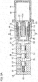
- Fig. 1 shows a spool valve of one embodiment which comprises an electric motor section 10, a motion converter mechanism section 20 configured to covert a rotary motion to a linear motion, and a hydraulic control section 30.
- the electric motor section 10 comprises a motor case 11, and an electric motor 12 mounted in the motor case 11.
- the electric motor 123 has a rotary shaft 12a extending through an end plate 11a of the motor case 11, and protruding into the below-described nut case 28 connected to an end of the motor case 11.
- the motion converter mechanism section 20 includes a ball-screw 21, and a nut case 28 covering the ball-screw 21.
- the ball-screw 21 includes a threaded shaft 22 having a thread groove 23 in the outer periphery thereof, a nut 24 fitted around the threaded shaft 22, and balls 26 disposed between a thread groove 25 formed in the inner periphery of the nut 24 and the thread groove 23 of the threaded shaft 22.
- the nut 24 is fitted in an open end portion of a tubular nut holder 27 having a closed end so as to rotate together with the nut holder 27.
- the nut holder 27 is connected to the rotary shaft 12a of the electric motor 12 so as to be rotationally driven by the electric motor 12.
- the nut 24 and the nut holder 27 are entirely covered by the nut case 28, which is connected to the motor case 11, and are rotatably supported by a respective pair of rolling bearings 29 mounted in the nut case 28 at its respective ends.
- the hydraulic control section 30 includes a valve body 31 connected to the end of the nut case 28.
- the valve body 31 is formed with a spool insertion hole 32 extending through the valve body 31 from one to the other end thereof.
- the spool insertion hole 32 has a distal end closed by an end plate 33 connected to the valve body 31.
- the spool insertion hole 32 has a radially inner surface formed with a first circumferential groove 34, a second circumferential groove 35, and a third circumferential groove 36 which are arranged in this order from the end of the spool insertion hole 32 close to the ball-screw 21.
- the valve body 31 is formed, in its outer periphery, with an input port 37 communicating with the first circumferential groove 34, an output port 38 communicating with the second circumferential groove 35, and a drain port 39 communicating with the third circumferential groove 36.
- a shaft-shaped spool 40 is inserted in the spool insertion hole 32.
- the spool 40 is connected at one end portion thereof to the threaded shaft 22 of the ball-screw 21 so as to be not rotatable relative to the threaded shaft 22, and axially movable together with the threaded shaft 22.
- the spool 40 has a first land 41, a second land 42, and a third land 43 which are arranged in this order from the end of the spool 40 close to the threaded shaft 22 so as to be slidable along the radially inner surface of the spool insertion hole 32.
- the spool 40 is further formed with a groove-shaped first oil flow passage 44 between the first land 41 and the second land 42, which are adjacent to each other, and a groove-shaped second oil flow passage 45 between the second land 42 and the third land 43.
- the spool 40 is movable between a neutral position, where the second land 42 shuts off communication between the input port 37 and the output port 38 and between the output port 38 and the drain port 39, and a first position (high-speed position), shown in Fig. 2A , where the input port 37 and the output port 38 communicate with each other via the first oil flow passage 44, while the second land 42 shuts off communication between the output port 38 and the drain port 39, and is also movable between the neutral position and a second position (low-speed position), shown in Fig. 2B , where the second land 42 shuts off communication between the input port 37 and the output port 38, while the output port 38 an the drain port 39 communicate with each other via the second oil flow passage 45.
- An elastic member 46 is mounted in the spool insertion hole 32 at its closed end portion to bias the spool 40 toward the low-speed position.
- the elastic member 46 comprises a compression coil spring including axially extending bent pieces 46a and 46b at the respective ends thereof.
- the bent piece 46a is slidably inserted in an axial hole 47 formed in the distal end surface of the spool 40, while the bent piece 46b engages the end plate 33, which is connected to the valve body 31.
- the bent pieces 46a and 46b thus prevent rotation of the spool 40 and the threaded shaft 22.
- the input port 37 is brought into communication with the discharge port of an oil pump P via an oil passage Ti, while the output port 38 is brought into communication with an oil feed/discharge port of the cylinder S, which is configured to move a slide pulley member 51 of a driving pulley 50 of the V-belt type CVT toward a fixed pulley member 52 of the driving pulley 50, via an oil passage T 2 .
- This V-belt type CVT is configured to change the speed ratio by changing the dimeter of the portion of the V-belt 53 wound around the driving pulley 50 by moving the slide pulley member 51 toward and away from the fixed pulley member 52, and changing the diameter of the portion of the V-belt 53 wound around the driven pulley 54.
- Fig. 1 shows the neutral position of the spool 40 of the spool valve, where the spool 40 shuts off communication both between the input port 37 and the output port 38, and between the output port 38 and the drain port 39.
- the input port 37 communicates with the output port 38 via the first oil flow passage 44 of the spool 40, while the second land 42 of the spool 40 shuts off communication between the output port 38 and the drain port 39, as shown in Fig. 2A .
- oil delivered from the oil pump P is fed into the cylinder S, so that the slide pulley member 51 of the driving pulley 50 moves toward the fixed pulley member 52 of the driving pulley 50; that is, the driving pulley 50 is shifted toward the high-speed side.
- Fig. 1 shows the neutral position of the spool 40, where the second land 42 of the spool 40 shuts off communication between the input port 37 and the output port 38 and between the output port 38 and the drain port 39, so that the speed ratio of the V-belt type CVT remains unchanged.
- the spool 40 When the spool 40 is moved to the low-speed position, the spool 40 shuts off communication between the input port 37 and the output port 38, while allowing communication between the output port 38 and the drain port 39. As a result, oil in the cylinder S is discharged through the output port 38 into the drain port 39, so that the slide pulley member 51 of the driving pulley 50 moves away from the fixed pulley member 52, that is, the driving pulley 50 is shifted toward the low-speed side.
- the spool valve according to the present invention is configured such that the spool 40 is moved axially by driving the electric motor 12 and thus actuating the ball-screw 21, the spool 40 can be moved a longer distance than the spool of a conventional spool valve which is moved by a solenoid. Since the spool 40 is moved a longer distance, it is possible to increase the sectional areas of the input port 37, the output port 38, the drain port 39, and the oil passages T 1 and T 2 , to which the input port 37 and the output port 38 are respectively connected, and thus to more quickly shift the V-belt type CVT.
- the threaded shaft 22 may be connected, as shown in Fig. 3A , to the rotary shaft 12a of the electric motor 12 such that the nut 24 is moved axially by rotating the threaded shaft 22.
- the nut 24 is supported by a linear ball bearing 60 so as to be not rotatable and axially movable, and the elastic member 46 biasing the spool 40 toward the low-speed position is a compression coil spring having no bent pieces 46a and 46b.
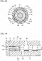
- the linear ball bearing 60 rotationally fixing the nut 24 includes an outer race 61 press-fitted in the radially inner surface of the nut case 28, and a retainer 62 mounted in the outer race 61 and formed with a plurality of elongated guide grooves 63 circumferentially spaced apart from, and extending parallel, to each other.
- the guide grooves 63 comprise a plurality pairs of linear raceway grooves 63a and 63b, of which the linear raceway grooves 63a are elongated holes open at the radially inner surface of the retainer 62.
- a large number of balls 64 are received in each guide groove 63 so as to be capable of rolling along a rolling surface 65 formed on the radially inner surface of the outer race 61.
- the balls 64 received in the linear raceway grooves 63a each partially protrude radially inwardly beyond the radially inner surface of the retainer 62 so as to be capable of rolling along the corresponding one of linear grooves 66 formed in the outer periphery of the nut 24.
- the retainer 62 thus supports the nut 24 so as to be axially movable but not rotatable.
- the threaded shaft 22 of the ball-screw 21, which is driven linearly is rotationally fixed in position by the elastic member 46
- the nut 24 of the ball-screw 21, which is driven linearly is rotationally fixed in position by the linear ball bearing 60.
- a different means may be used to rotationally fix the linearly driven member.
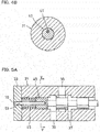
- Figs. 4A and 4B , and 5A and 5B show, respectively, other rotational fixing means for rotationally fixing one of the threaded shaft 22 and the nut 24 that is driven linearly.
- the rotational fixing means shown in Figs. 4A and 4B comprises a guide pin 67 extending from the distal end surface of the spool 40 at its off-center position, and a pin hole 68 formed in the end plate 33, which is connected to the valve body 31, such that the guide pin 67 is slidably inserted in the pin hole 68.
- the rotational fixing means shown in Figs. 4A and 4B thus rotationally fixes the spool 40, thereby rotationally fixing one of the threaded shaft 22 and the nut 24 that drives the spool 40 in the axial direction.
- the rotational fixing means shown in Figs. 5A and 5B comprises a guide pin 69 extending from the distal end surface of the spool 40 at its center, and having a non-circular cross-section, and a pin hole 70 formed in the end plate 33, which is connected to the valve body 31, and having a non-circular cross-section such that the guide pin 69 is slidably inserted in the pin hole 70.
- the rotational fixing means shown in Figs. 5A and 5B thus rotationally fixes the spool 40, thereby rotationally fixing one of the threaded shaft 22 and the nut 24 that drives the spool 40 in the axial direction.
- an end-cap type ball return mechanism shown in Fig. 6 may be used instead, which includes a pair of end caps 71 connected to the respective ends of the nut 24 such that the balls 26 are returned to the starting point through return paths 72 formed in the end caps 71 and the nut 24.
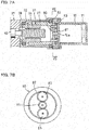
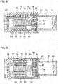
- Figs. 7A and 7B shows a different spool valve embodying the present invention.
- This spool valve differs from the spool valve shown in Fig. 1 in that the rotation of the rotary shaft 12a of the electric motor 12 is transmitted to the nut 24 after being reduced by a planetary gear reduction mechanism 80.
- elements corresponding to those of the spool valve of Fig. 1 are denoted by identical numerals, and their description is omitted.
- the planetary gear reduction mechanism 80 comprises a sun gear 81 mounted on the rotary shaft 12a of the electric motor 12, a stationary ring gear 82 mounted between the portions of the nut case 28 and the motor case 11 opposed to each other, pinions gears 83 each meshing with both the ring gear 82 and the sun gear 81, and the nut holder 27, which serves as a carrier to support the pinion gears 83.
- the planetary gear reduction mechanism 80 is configured such that when the sun gear 81 is rotated, the pinion gears 83 are rotated about their respective axes while being revolved around the sun gear 81, whereby the nut holder 27 and the nut 24, which is supported by the nut holder 27, are rotated at a reduced speed.
- Fig. 8 shows another spool valve embodying the present invention which differs from the spool valve shown in Figs. 3A and 3B in that the rotation of the rotary shaft 12a of the electric motor 12 is transmitted to the threaded shaft 22 after being reduced by a planetary gear reduction mechanism 80 similar to the one shown in Figs. 7A and 7B .
- Fig. 9 shows still another spool valve embodying the present invention which differs from the spool valve shown in Fig. 6 in that the rotation of the rotary shaft 12a of the electric motor 12 is transmitted to the threaded shaft 22 after being reduced by the planetary gear reduction mechanism 80 shown in Fig. 8 .
- the axial length of either of the spool valves shown in Figs. 8 and 9 can be made smaller than those of the spool valves shown in Figs. 3A and 3B , and Fig. 6 .
- the planetary gear reduction mechanisms 80 shown in Figs. 8 and 9 each include a carrier 84 rotatably supporting the pinion gears 83 and fixed to the threaded shaft 22 so as to rotate together with the threaded shaft 22.
- Fig. 10 shows still another spool valve embodying the present invention, of which the electric motor 12 is arranged in parallel with the threaded shaft 22 of the ball-screw 21 such that the rotation of the rotary shaft 12a of the electric motor 12 is transmitted to the nut 24 of the ball-screw 21 by way of a spur gear reduction mechanism 85.
- the electric motor 12 and the ball-screw 21 are received in a single case 86.
- a guide tube 87 is mounted in a portion of the case 86 so as to be coaxial with the threaded shaft 22.
- the guide tube 87 has an inner periphery formed with axial guide grooves 88 in which are slidably inserted guide pins 89 provided on the threaded shaft 22 to rotationally fix the threaded shaft 22.
- the spool valve shown in Fig. 10 is identical to the spool valve shown in Fig. 1 .
- elements corresponding to those of the spool valve of Fig. 1 are denoted by identical numerals, and their description is omitted.
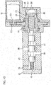
- Fig. 11 shows still another spool valve embodying the present invention, of which the ball-screw 21, which converts the rotation of the rotary shaft 12a of the electric motor 12 to linear motion, is mounted in the spool insertion hole 32 formed in the valve body 31, with the threaded shaft 22 of the ball-screw 21 connected to the rotary shaft 12a such that the nut 24, which is in threaded engagement with the threaded shaft 22 by way of the balls 26, serves as the spool of the spool valve.
- the nut 24 is formed with the first to third lands 41, 42 and 43, and the first and second oil flow passages 44 and 45 between the adjacent lands.
- the nut 24, as the spool, is provided with a guide pin 90 on its outer periphery which is slidably inserted in an axial groove 91 formed in the inner periphery of the spool insertion hole 32 so that the nut 24 is slidable but not rotatable.
Landscapes
- Engineering & Computer Science (AREA)
- General Engineering & Computer Science (AREA)
- Mechanical Engineering (AREA)
- Chemical & Material Sciences (AREA)
- Combustion & Propulsion (AREA)
- Transportation (AREA)
- Physics & Mathematics (AREA)
- Fluid Mechanics (AREA)
- Electrically Driven Valve-Operating Means (AREA)
- Mechanically-Actuated Valves (AREA)
- Transmission Devices (AREA)
- Multiple-Way Valves (AREA)
Applications Claiming Priority (2)
| Application Number | Priority Date | Filing Date | Title |
|---|---|---|---|
| JP2014156595A JP6400372B2 (ja) | 2014-07-31 | 2014-07-31 | スプールバルブ |
| PCT/JP2015/070546 WO2016017458A1 (fr) | 2014-07-31 | 2015-07-17 | Distributeur à tiroir cylindrique |
Publications (3)
| Publication Number | Publication Date |
|---|---|
| EP3176479A1 true EP3176479A1 (fr) | 2017-06-07 |
| EP3176479A4 EP3176479A4 (fr) | 2017-07-19 |
| EP3176479B1 EP3176479B1 (fr) | 2018-10-31 |
Family
ID=55217362
Family Applications (1)
| Application Number | Title | Priority Date | Filing Date |
|---|---|---|---|
| EP15826598.3A Not-in-force EP3176479B1 (fr) | 2014-07-31 | 2015-07-17 | Distributeur à tiroir cylindrique |
Country Status (5)
| Country | Link |
|---|---|
| US (1) | US10794483B2 (fr) |
| EP (1) | EP3176479B1 (fr) |
| JP (1) | JP6400372B2 (fr) |
| CN (1) | CN106662266B (fr) |
| WO (1) | WO2016017458A1 (fr) |
Families Citing this family (23)
| Publication number | Priority date | Publication date | Assignee | Title |
|---|---|---|---|---|
| JP2016161072A (ja) * | 2015-03-03 | 2016-09-05 | Ntn株式会社 | 油圧制御弁 |
| JP2018044636A (ja) * | 2016-09-15 | 2018-03-22 | Ntn株式会社 | 電動アクチュエータ |
| JP6877175B2 (ja) * | 2017-02-21 | 2021-05-26 | 川崎重工業株式会社 | スプール弁 |
| JP7146369B2 (ja) * | 2017-03-29 | 2022-10-04 | Ntn株式会社 | 電動アクチュエータおよび電動アクチュエータの製造方法 |
| JP6955405B2 (ja) * | 2017-09-12 | 2021-10-27 | 川崎重工業株式会社 | スプール弁装置、及びスプール弁 |
| DE102017125819A1 (de) * | 2017-11-06 | 2019-05-09 | Kiekert Ag | Stellantrieb für kraftfahrzeugtechnische Anwendungen |
| JP7037370B2 (ja) * | 2018-01-12 | 2022-03-16 | 川崎重工業株式会社 | スプール弁 |
| WO2019155932A1 (fr) * | 2018-02-09 | 2019-08-15 | キヤノン電子株式会社 | Électrovanne |
| US11408531B2 (en) | 2018-05-17 | 2022-08-09 | Kawasaki Jukogyo Kabushiki Kaisha | Spool valve |
| KR102726554B1 (ko) * | 2018-11-02 | 2024-11-06 | 주식회사 대동 | 수동 절환식 플로팅 밸브 |
| CN112996982B (zh) * | 2018-11-09 | 2023-10-27 | 芙罗服务管理公司 | 流体交换设备以及相关系统和方法 |
| CN111765269B (zh) * | 2019-04-01 | 2021-08-24 | 浙江盾安禾田金属有限公司 | 切换阀及具有其的制冷系统 |
| CN110388478A (zh) * | 2019-07-03 | 2019-10-29 | 中国石油集团渤海钻探工程有限公司 | 流体控制器 |
| CN110296118B (zh) * | 2019-08-05 | 2024-04-02 | 安徽理工大学 | 一种应用于双自由度转阀阀芯的自动切换结构 |
| FR3100299B1 (fr) * | 2019-09-02 | 2021-07-30 | Zodiac Actuation Systems | Vis inversee a billes multi-pistes |
| CN110886655A (zh) * | 2019-11-22 | 2020-03-17 | 中国航发西安动力控制科技有限公司 | 用于航空发动机加力燃油系统的活门 |
| EP3835625B1 (fr) | 2019-12-09 | 2024-08-07 | Ningbo Geely Automobile Research & Development Co. Ltd. | Système d'actionneur pour une transmission de véhicule, véhicule comprenant un système d'actionneur et procédé de fonctionnement d'un système d'actionneur |
| JP2021148215A (ja) * | 2020-03-19 | 2021-09-27 | 株式会社鷺宮製作所 | 電動弁および冷凍サイクルシステム |
| CA3138135C (fr) * | 2021-01-05 | 2026-03-17 | The Boeing Company | Assemblage de bobine de selecteur de circuit |
| CN113915376B (zh) * | 2021-11-04 | 2024-04-30 | 哈尔滨工业大学 | 一种数字阀的传动转换器 |
| CN116220611B (zh) * | 2023-02-06 | 2023-09-01 | 江苏苏盐阀门机械有限公司 | 一种防腐蚀油井阀门 |
| CN116498613B (zh) * | 2023-04-13 | 2025-08-12 | 杭州玖清科技有限公司 | 一种面向清洁能源精准压缩用的电液伺服流量阀 |
| WO2024254837A1 (fr) | 2023-06-16 | 2024-12-19 | Sharkninja Operating Llc | Buses de mélange de carbonatation |
Family Cites Families (20)
| Publication number | Priority date | Publication date | Assignee | Title |
|---|---|---|---|---|
| US2738684A (en) * | 1949-10-21 | 1956-03-20 | Mansfield Dev Inc | Operating mechanism for high pressure valves |
| US2966891A (en) * | 1958-11-04 | 1961-01-03 | John G Williams | Simplified power relay assembly |
| DE2141519A1 (de) | 1971-08-19 | 1973-02-22 | Kloeckner Humboldt Deutz Ag | Motorantrieb fuer steuerorgane |
| JPH0665912B2 (ja) | 1984-08-28 | 1994-08-24 | 宇部興産株式会社 | 流量制御弁 |
| JPS6175563U (fr) * | 1984-10-24 | 1986-05-21 | ||
| JPS6175563A (ja) | 1985-09-20 | 1986-04-17 | Hitachi Ltd | 固体撮像素子 |
| US5005442A (en) * | 1987-12-11 | 1991-04-09 | Aisin Aw Co., Ltd. | Control system for stepless belt transmissions |
| US4951549A (en) * | 1988-12-12 | 1990-08-28 | Olsen Controls, Inc. | Digital servo valve system |
| DE4131500A1 (de) * | 1991-09-21 | 1993-03-25 | Bosch Gmbh Robert | Elektromagnetisch betaetigbares einspritzventil |
| JP2631635B2 (ja) * | 1995-01-12 | 1997-07-16 | 日本ベーレー株式会社 | 電動式調節弁駆動用リニアアクチュエータ |
| JP2000028023A (ja) * | 1998-07-15 | 2000-01-25 | Ube Ind Ltd | ボールねじ駆動の油圧制御弁 |
| JP4069312B2 (ja) | 1999-02-03 | 2008-04-02 | 株式会社鷺宮製作所 | 電動式コントロールバルブ |
| US7066189B2 (en) * | 2002-12-20 | 2006-06-27 | Control Components, Inc. | Predictive maintenance and initialization system for a digital servovalve |
| JP2009058013A (ja) * | 2007-08-30 | 2009-03-19 | Aisin Aw Co Ltd | 電磁弁 |
| US20110023513A1 (en) * | 2009-07-28 | 2011-02-03 | Hamilton Sundstrand Corporation | Expansion valve for a refrigerant system |
| US8636262B2 (en) * | 2009-11-13 | 2014-01-28 | Fisher Controls International, Llc | Coupling apparatus for use with electric actuators |
| JP5666174B2 (ja) * | 2010-06-11 | 2015-02-12 | ナブテスコ株式会社 | 多連方向切換弁 |
| US9518672B2 (en) * | 2010-06-21 | 2016-12-13 | Cameron International Corporation | Electronically actuated gate valve |
| EP2832596B1 (fr) | 2012-03-30 | 2017-04-19 | Honda Motor Co., Ltd. | Dispositif de freinage |
| CN203477484U (zh) | 2013-09-02 | 2014-03-12 | 上海开维喜阀门集团有限公司 | 超低温轴流式止回阀 |
-
2014
- 2014-07-31 JP JP2014156595A patent/JP6400372B2/ja not_active Expired - Fee Related
-
2015
- 2015-07-17 WO PCT/JP2015/070546 patent/WO2016017458A1/fr not_active Ceased
- 2015-07-17 US US15/500,303 patent/US10794483B2/en not_active Expired - Fee Related
- 2015-07-17 CN CN201580036609.7A patent/CN106662266B/zh not_active Expired - Fee Related
- 2015-07-17 EP EP15826598.3A patent/EP3176479B1/fr not_active Not-in-force
Also Published As
| Publication number | Publication date |
|---|---|
| EP3176479A4 (fr) | 2017-07-19 |
| EP3176479B1 (fr) | 2018-10-31 |
| JP6400372B2 (ja) | 2018-10-03 |
| US20170211699A1 (en) | 2017-07-27 |
| WO2016017458A1 (fr) | 2016-02-04 |
| CN106662266B (zh) | 2020-03-06 |
| JP2016033400A (ja) | 2016-03-10 |
| US10794483B2 (en) | 2020-10-06 |
| CN106662266A (zh) | 2017-05-10 |
Similar Documents
| Publication | Publication Date | Title |
|---|---|---|
| EP3176479B1 (fr) | Distributeur à tiroir cylindrique | |
| DE60204713T2 (de) | Ein verbessertes stufenloses getriebe | |
| US4909776A (en) | Continuously variable transmission | |
| CN102338210B (zh) | 自动变速器 | |
| DE10132334A1 (de) | Planetenräderwerk für einen Traktionsantrieb mit einem über Zahnräder hergestellten, neutralen Zustand | |
| US11815179B2 (en) | Actuator for transmission | |
| DE112010005594T5 (de) | Kontinuierlich variables Getriebe der Riemenbauart | |
| EP1158207B1 (fr) | REducteur de positionnement axial pour variateur. variateur et transmission a changement de vitesses continu. | |
| EP3073150A1 (fr) | Transmission à variation continue à courroie en v | |
| DE60036977T2 (de) | Kraftübertragungsmechanismus | |
| EP1781969B1 (fr) | Transmission a variation continue a disques coniques, procede de fabrication de ladite transmission et vehicule equipe de cette transmission | |
| JP5759105B2 (ja) | 油圧制御弁 | |
| KR20150029223A (ko) | 무한 변속기 | |
| US5187995A (en) | Shift control system for continuously variable traction roller transmission | |
| WO2016139106A1 (fr) | Transmission à variation continue à commande améliorée | |
| DE3118805A1 (de) | "linearantriebseinheit" | |
| JP2018044585A (ja) | 油圧制御装置 | |
| DE102018212995B4 (de) | Anlasseinrichtung für eine Brennkraftmaschine | |
| WO2016086930A1 (fr) | Boîte de vitesses à roues planétaires | |
| JP5117946B2 (ja) | ボールねじ | |
| KR101433077B1 (ko) | 자동 변속기 | |
| WO2016139107A1 (fr) | Transmission à variation continue à commande améliorée | |
| JP2010106887A (ja) | 動力伝達装置の潤滑機構 | |
| JP4039272B2 (ja) | ベルト式無段変速機 | |
| JP2001080539A (ja) | 作業機の操向装置 |
Legal Events
| Date | Code | Title | Description |
|---|---|---|---|
| STAA | Information on the status of an ep patent application or granted ep patent |
Free format text: STATUS: THE INTERNATIONAL PUBLICATION HAS BEEN MADE |
|
| 17P | Request for examination filed |
Effective date: 20170206 |
|
| AK | Designated contracting states |
Kind code of ref document: A1 Designated state(s): AL AT BE BG CH CY CZ DE DK EE ES FI FR GB GR HR HU IE IS IT LI LT LU LV MC MK MT NL NO PL PT RO RS SE SI SK SM TR |
|
| AX | Request for extension of the european patent |
Extension state: BA ME |
|
| PUAI | Public reference made under article 153(3) epc to a published international application that has entered the european phase |
Free format text: ORIGINAL CODE: 0009012 |
|
| STAA | Information on the status of an ep patent application or granted ep patent |
Free format text: STATUS: REQUEST FOR EXAMINATION WAS MADE |
|
| A4 | Supplementary search report drawn up and despatched |
Effective date: 20170620 |
|
| RIC1 | Information provided on ipc code assigned before grant |
Ipc: F16K 31/53 20060101ALI20170613BHEP Ipc: F16K 31/50 20060101ALI20170613BHEP Ipc: F16K 31/04 20060101AFI20170613BHEP Ipc: F16H 61/02 20060101ALI20170613BHEP Ipc: F16H 25/20 20060101ALI20170613BHEP Ipc: F16K 11/07 20060101ALI20170613BHEP |
|
| DAV | Request for validation of the european patent (deleted) | ||
| DAX | Request for extension of the european patent (deleted) | ||
| GRAP | Despatch of communication of intention to grant a patent |
Free format text: ORIGINAL CODE: EPIDOSNIGR1 |
|
| STAA | Information on the status of an ep patent application or granted ep patent |
Free format text: STATUS: GRANT OF PATENT IS INTENDED |
|
| INTG | Intention to grant announced |
Effective date: 20180612 |
|
| GRAS | Grant fee paid |
Free format text: ORIGINAL CODE: EPIDOSNIGR3 |
|
| GRAA | (expected) grant |
Free format text: ORIGINAL CODE: 0009210 |
|
| STAA | Information on the status of an ep patent application or granted ep patent |
Free format text: STATUS: THE PATENT HAS BEEN GRANTED |
|
| AK | Designated contracting states |
Kind code of ref document: B1 Designated state(s): AL AT BE BG CH CY CZ DE DK EE ES FI FR GB GR HR HU IE IS IT LI LT LU LV MC MK MT NL NO PL PT RO RS SE SI SK SM TR |
|
| REG | Reference to a national code |
Ref country code: CH Ref legal event code: EP Ref country code: GB Ref legal event code: FG4D |
|
| REG | Reference to a national code |
Ref country code: AT Ref legal event code: REF Ref document number: 1059808 Country of ref document: AT Kind code of ref document: T Effective date: 20181115 |
|
| REG | Reference to a national code |
Ref country code: DE Ref legal event code: R096 Ref document number: 602015019301 Country of ref document: DE |
|
| REG | Reference to a national code |
Ref country code: IE Ref legal event code: FG4D |
|
| REG | Reference to a national code |
Ref country code: NL Ref legal event code: MP Effective date: 20181031 |
|
| REG | Reference to a national code |
Ref country code: LT Ref legal event code: MG4D |
|
| REG | Reference to a national code |
Ref country code: AT Ref legal event code: MK05 Ref document number: 1059808 Country of ref document: AT Kind code of ref document: T Effective date: 20181031 |
|
| PG25 | Lapsed in a contracting state [announced via postgrant information from national office to epo] |
Ref country code: AT Free format text: LAPSE BECAUSE OF FAILURE TO SUBMIT A TRANSLATION OF THE DESCRIPTION OR TO PAY THE FEE WITHIN THE PRESCRIBED TIME-LIMIT Effective date: 20181031 Ref country code: HR Free format text: LAPSE BECAUSE OF FAILURE TO SUBMIT A TRANSLATION OF THE DESCRIPTION OR TO PAY THE FEE WITHIN THE PRESCRIBED TIME-LIMIT Effective date: 20181031 Ref country code: PL Free format text: LAPSE BECAUSE OF FAILURE TO SUBMIT A TRANSLATION OF THE DESCRIPTION OR TO PAY THE FEE WITHIN THE PRESCRIBED TIME-LIMIT Effective date: 20181031 Ref country code: IS Free format text: LAPSE BECAUSE OF FAILURE TO SUBMIT A TRANSLATION OF THE DESCRIPTION OR TO PAY THE FEE WITHIN THE PRESCRIBED TIME-LIMIT Effective date: 20190228 Ref country code: LT Free format text: LAPSE BECAUSE OF FAILURE TO SUBMIT A TRANSLATION OF THE DESCRIPTION OR TO PAY THE FEE WITHIN THE PRESCRIBED TIME-LIMIT Effective date: 20181031 Ref country code: NO Free format text: LAPSE BECAUSE OF FAILURE TO SUBMIT A TRANSLATION OF THE DESCRIPTION OR TO PAY THE FEE WITHIN THE PRESCRIBED TIME-LIMIT Effective date: 20190131 Ref country code: BG Free format text: LAPSE BECAUSE OF FAILURE TO SUBMIT A TRANSLATION OF THE DESCRIPTION OR TO PAY THE FEE WITHIN THE PRESCRIBED TIME-LIMIT Effective date: 20190131 Ref country code: FI Free format text: LAPSE BECAUSE OF FAILURE TO SUBMIT A TRANSLATION OF THE DESCRIPTION OR TO PAY THE FEE WITHIN THE PRESCRIBED TIME-LIMIT Effective date: 20181031 Ref country code: LV Free format text: LAPSE BECAUSE OF FAILURE TO SUBMIT A TRANSLATION OF THE DESCRIPTION OR TO PAY THE FEE WITHIN THE PRESCRIBED TIME-LIMIT Effective date: 20181031 |
|
| PG25 | Lapsed in a contracting state [announced via postgrant information from national office to epo] |
Ref country code: PT Free format text: LAPSE BECAUSE OF FAILURE TO SUBMIT A TRANSLATION OF THE DESCRIPTION OR TO PAY THE FEE WITHIN THE PRESCRIBED TIME-LIMIT Effective date: 20190301 Ref country code: RS Free format text: LAPSE BECAUSE OF FAILURE TO SUBMIT A TRANSLATION OF THE DESCRIPTION OR TO PAY THE FEE WITHIN THE PRESCRIBED TIME-LIMIT Effective date: 20181031 Ref country code: SE Free format text: LAPSE BECAUSE OF FAILURE TO SUBMIT A TRANSLATION OF THE DESCRIPTION OR TO PAY THE FEE WITHIN THE PRESCRIBED TIME-LIMIT Effective date: 20181031 Ref country code: GR Free format text: LAPSE BECAUSE OF FAILURE TO SUBMIT A TRANSLATION OF THE DESCRIPTION OR TO PAY THE FEE WITHIN THE PRESCRIBED TIME-LIMIT Effective date: 20190201 Ref country code: AL Free format text: LAPSE BECAUSE OF FAILURE TO SUBMIT A TRANSLATION OF THE DESCRIPTION OR TO PAY THE FEE WITHIN THE PRESCRIBED TIME-LIMIT Effective date: 20181031 Ref country code: NL Free format text: LAPSE BECAUSE OF FAILURE TO SUBMIT A TRANSLATION OF THE DESCRIPTION OR TO PAY THE FEE WITHIN THE PRESCRIBED TIME-LIMIT Effective date: 20181031 |
|
| PG25 | Lapsed in a contracting state [announced via postgrant information from national office to epo] |
Ref country code: DK Free format text: LAPSE BECAUSE OF FAILURE TO SUBMIT A TRANSLATION OF THE DESCRIPTION OR TO PAY THE FEE WITHIN THE PRESCRIBED TIME-LIMIT Effective date: 20181031 Ref country code: CZ Free format text: LAPSE BECAUSE OF FAILURE TO SUBMIT A TRANSLATION OF THE DESCRIPTION OR TO PAY THE FEE WITHIN THE PRESCRIBED TIME-LIMIT Effective date: 20181031 Ref country code: IT Free format text: LAPSE BECAUSE OF FAILURE TO SUBMIT A TRANSLATION OF THE DESCRIPTION OR TO PAY THE FEE WITHIN THE PRESCRIBED TIME-LIMIT Effective date: 20181031 Ref country code: ES Free format text: LAPSE BECAUSE OF FAILURE TO SUBMIT A TRANSLATION OF THE DESCRIPTION OR TO PAY THE FEE WITHIN THE PRESCRIBED TIME-LIMIT Effective date: 20181031 |
|
| REG | Reference to a national code |
Ref country code: DE Ref legal event code: R097 Ref document number: 602015019301 Country of ref document: DE |
|
| PG25 | Lapsed in a contracting state [announced via postgrant information from national office to epo] |
Ref country code: RO Free format text: LAPSE BECAUSE OF FAILURE TO SUBMIT A TRANSLATION OF THE DESCRIPTION OR TO PAY THE FEE WITHIN THE PRESCRIBED TIME-LIMIT Effective date: 20181031 Ref country code: SM Free format text: LAPSE BECAUSE OF FAILURE TO SUBMIT A TRANSLATION OF THE DESCRIPTION OR TO PAY THE FEE WITHIN THE PRESCRIBED TIME-LIMIT Effective date: 20181031 Ref country code: EE Free format text: LAPSE BECAUSE OF FAILURE TO SUBMIT A TRANSLATION OF THE DESCRIPTION OR TO PAY THE FEE WITHIN THE PRESCRIBED TIME-LIMIT Effective date: 20181031 Ref country code: SK Free format text: LAPSE BECAUSE OF FAILURE TO SUBMIT A TRANSLATION OF THE DESCRIPTION OR TO PAY THE FEE WITHIN THE PRESCRIBED TIME-LIMIT Effective date: 20181031 |
|
| PLBE | No opposition filed within time limit |
Free format text: ORIGINAL CODE: 0009261 |
|
| STAA | Information on the status of an ep patent application or granted ep patent |
Free format text: STATUS: NO OPPOSITION FILED WITHIN TIME LIMIT |
|
| 26N | No opposition filed |
Effective date: 20190801 |
|
| PG25 | Lapsed in a contracting state [announced via postgrant information from national office to epo] |
Ref country code: SI Free format text: LAPSE BECAUSE OF FAILURE TO SUBMIT A TRANSLATION OF THE DESCRIPTION OR TO PAY THE FEE WITHIN THE PRESCRIBED TIME-LIMIT Effective date: 20181031 |
|
| PG25 | Lapsed in a contracting state [announced via postgrant information from national office to epo] |
Ref country code: MC Free format text: LAPSE BECAUSE OF FAILURE TO SUBMIT A TRANSLATION OF THE DESCRIPTION OR TO PAY THE FEE WITHIN THE PRESCRIBED TIME-LIMIT Effective date: 20181031 |
|
| REG | Reference to a national code |
Ref country code: CH Ref legal event code: PL |
|
| GBPC | Gb: european patent ceased through non-payment of renewal fee |
Effective date: 20190717 |
|
| PG25 | Lapsed in a contracting state [announced via postgrant information from national office to epo] |
Ref country code: TR Free format text: LAPSE BECAUSE OF FAILURE TO SUBMIT A TRANSLATION OF THE DESCRIPTION OR TO PAY THE FEE WITHIN THE PRESCRIBED TIME-LIMIT Effective date: 20181031 |
|
| REG | Reference to a national code |
Ref country code: BE Ref legal event code: MM Effective date: 20190731 |
|
| PG25 | Lapsed in a contracting state [announced via postgrant information from national office to epo] |
Ref country code: GB Free format text: LAPSE BECAUSE OF NON-PAYMENT OF DUE FEES Effective date: 20190717 |
|
| PG25 | Lapsed in a contracting state [announced via postgrant information from national office to epo] |
Ref country code: BE Free format text: LAPSE BECAUSE OF NON-PAYMENT OF DUE FEES Effective date: 20190731 Ref country code: CH Free format text: LAPSE BECAUSE OF NON-PAYMENT OF DUE FEES Effective date: 20190731 Ref country code: LU Free format text: LAPSE BECAUSE OF NON-PAYMENT OF DUE FEES Effective date: 20190717 Ref country code: LI Free format text: LAPSE BECAUSE OF NON-PAYMENT OF DUE FEES Effective date: 20190731 |
|
| PG25 | Lapsed in a contracting state [announced via postgrant information from national office to epo] |
Ref country code: IE Free format text: LAPSE BECAUSE OF NON-PAYMENT OF DUE FEES Effective date: 20190717 |
|
| PG25 | Lapsed in a contracting state [announced via postgrant information from national office to epo] |
Ref country code: CY Free format text: LAPSE BECAUSE OF FAILURE TO SUBMIT A TRANSLATION OF THE DESCRIPTION OR TO PAY THE FEE WITHIN THE PRESCRIBED TIME-LIMIT Effective date: 20181031 |
|
| PG25 | Lapsed in a contracting state [announced via postgrant information from national office to epo] |
Ref country code: MT Free format text: LAPSE BECAUSE OF FAILURE TO SUBMIT A TRANSLATION OF THE DESCRIPTION OR TO PAY THE FEE WITHIN THE PRESCRIBED TIME-LIMIT Effective date: 20181031 Ref country code: HU Free format text: LAPSE BECAUSE OF FAILURE TO SUBMIT A TRANSLATION OF THE DESCRIPTION OR TO PAY THE FEE WITHIN THE PRESCRIBED TIME-LIMIT; INVALID AB INITIO Effective date: 20150717 |
|
| PGFP | Annual fee paid to national office [announced via postgrant information from national office to epo] |
Ref country code: FR Payment date: 20210611 Year of fee payment: 7 |
|
| PGFP | Annual fee paid to national office [announced via postgrant information from national office to epo] |
Ref country code: DE Payment date: 20210622 Year of fee payment: 7 |
|
| PG25 | Lapsed in a contracting state [announced via postgrant information from national office to epo] |
Ref country code: MK Free format text: LAPSE BECAUSE OF FAILURE TO SUBMIT A TRANSLATION OF THE DESCRIPTION OR TO PAY THE FEE WITHIN THE PRESCRIBED TIME-LIMIT Effective date: 20181031 |
|
| REG | Reference to a national code |
Ref country code: DE Ref legal event code: R119 Ref document number: 602015019301 Country of ref document: DE |
|
| PG25 | Lapsed in a contracting state [announced via postgrant information from national office to epo] |
Ref country code: FR Free format text: LAPSE BECAUSE OF NON-PAYMENT OF DUE FEES Effective date: 20220731 |
|
| PG25 | Lapsed in a contracting state [announced via postgrant information from national office to epo] |
Ref country code: DE Free format text: LAPSE BECAUSE OF NON-PAYMENT OF DUE FEES Effective date: 20230201 |