WO2016017458A1 - Distributeur à tiroir cylindrique - Google Patents
Distributeur à tiroir cylindrique Download PDFInfo
- Publication number
- WO2016017458A1 WO2016017458A1 PCT/JP2015/070546 JP2015070546W WO2016017458A1 WO 2016017458 A1 WO2016017458 A1 WO 2016017458A1 JP 2015070546 W JP2015070546 W JP 2015070546W WO 2016017458 A1 WO2016017458 A1 WO 2016017458A1
- Authority
- WO
- WIPO (PCT)
- Prior art keywords
- spool
- electric motor
- ball screw
- output port
- axial direction
- Prior art date
- Legal status (The legal status is an assumption and is not a legal conclusion. Google has not performed a legal analysis and makes no representation as to the accuracy of the status listed.)
- Ceased
Links
Images







Classifications
-
- F—MECHANICAL ENGINEERING; LIGHTING; HEATING; WEAPONS; BLASTING
- F16—ENGINEERING ELEMENTS AND UNITS; GENERAL MEASURES FOR PRODUCING AND MAINTAINING EFFECTIVE FUNCTIONING OF MACHINES OR INSTALLATIONS; THERMAL INSULATION IN GENERAL
- F16H—GEARING
- F16H61/00—Control functions within control units of change-speed- or reversing-gearings for conveying rotary motion ; Control of exclusively fluid gearing, friction gearing, gearings with endless flexible members or other particular types of gearing
- F16H61/66—Control functions within control units of change-speed- or reversing-gearings for conveying rotary motion ; Control of exclusively fluid gearing, friction gearing, gearings with endless flexible members or other particular types of gearing specially adapted for continuously variable gearings
- F16H61/662—Control functions within control units of change-speed- or reversing-gearings for conveying rotary motion ; Control of exclusively fluid gearing, friction gearing, gearings with endless flexible members or other particular types of gearing specially adapted for continuously variable gearings with endless flexible members
- F16H61/66254—Control functions within control units of change-speed- or reversing-gearings for conveying rotary motion ; Control of exclusively fluid gearing, friction gearing, gearings with endless flexible members or other particular types of gearing specially adapted for continuously variable gearings with endless flexible members controlling of shifting being influenced by a signal derived from the engine and the main coupling
- F16H61/66259—Control functions within control units of change-speed- or reversing-gearings for conveying rotary motion ; Control of exclusively fluid gearing, friction gearing, gearings with endless flexible members or other particular types of gearing specially adapted for continuously variable gearings with endless flexible members controlling of shifting being influenced by a signal derived from the engine and the main coupling using electrical or electronical sensing or control means
-
- F—MECHANICAL ENGINEERING; LIGHTING; HEATING; WEAPONS; BLASTING
- F16—ENGINEERING ELEMENTS AND UNITS; GENERAL MEASURES FOR PRODUCING AND MAINTAINING EFFECTIVE FUNCTIONING OF MACHINES OR INSTALLATIONS; THERMAL INSULATION IN GENERAL
- F16H—GEARING
- F16H63/00—Control outputs from the control unit to change-speed- or reversing-gearings for conveying rotary motion or to other devices than the final output mechanism
- F16H63/02—Final output mechanisms therefor; Actuating means for the final output mechanisms
- F16H63/04—Final output mechanisms therefor; Actuating means for the final output mechanisms a single final output mechanism being moved by a single final actuating mechanism
- F16H63/06—Final output mechanisms therefor; Actuating means for the final output mechanisms a single final output mechanism being moved by a single final actuating mechanism the final output mechanism having an indefinite number of positions
- F16H63/062—Final output mechanisms therefor; Actuating means for the final output mechanisms a single final output mechanism being moved by a single final actuating mechanism the final output mechanism having an indefinite number of positions electric or electro-mechanical actuating means
-
- B—PERFORMING OPERATIONS; TRANSPORTING
- B60—VEHICLES IN GENERAL
- B60W—CONJOINT CONTROL OF VEHICLE SUB-UNITS OF DIFFERENT TYPE OR DIFFERENT FUNCTION; CONTROL SYSTEMS SPECIALLY ADAPTED FOR HYBRID VEHICLES; ROAD VEHICLE DRIVE CONTROL SYSTEMS FOR PURPOSES NOT RELATED TO THE CONTROL OF A PARTICULAR SUB-UNIT
- B60W10/00—Conjoint control of vehicle sub-units of different type or different function
- B60W10/04—Conjoint control of vehicle sub-units of different type or different function including control of propulsion units
-
- B—PERFORMING OPERATIONS; TRANSPORTING
- B60—VEHICLES IN GENERAL
- B60W—CONJOINT CONTROL OF VEHICLE SUB-UNITS OF DIFFERENT TYPE OR DIFFERENT FUNCTION; CONTROL SYSTEMS SPECIALLY ADAPTED FOR HYBRID VEHICLES; ROAD VEHICLE DRIVE CONTROL SYSTEMS FOR PURPOSES NOT RELATED TO THE CONTROL OF A PARTICULAR SUB-UNIT
- B60W10/00—Conjoint control of vehicle sub-units of different type or different function
- B60W10/10—Conjoint control of vehicle sub-units of different type or different function including control of change-speed gearings
- B60W10/101—Infinitely variable gearings
-
- F—MECHANICAL ENGINEERING; LIGHTING; HEATING; WEAPONS; BLASTING
- F15—FLUID-PRESSURE ACTUATORS; HYDRAULICS OR PNEUMATICS IN GENERAL
- F15B—SYSTEMS ACTING BY MEANS OF FLUIDS IN GENERAL; FLUID-PRESSURE ACTUATORS, e.g. SERVOMOTORS; DETAILS OF FLUID-PRESSURE SYSTEMS, NOT OTHERWISE PROVIDED FOR
- F15B13/00—Details of servomotor systems ; Valves for servomotor systems
- F15B13/02—Fluid distribution or supply devices characterised by their adaptation to the control of servomotors
- F15B13/04—Fluid distribution or supply devices characterised by their adaptation to the control of servomotors for use with a single servomotor
- F15B13/0401—Valve members; Fluid interconnections therefor
- F15B13/0402—Valve members; Fluid interconnections therefor for linearly sliding valves, e.g. spool valves
-
- F—MECHANICAL ENGINEERING; LIGHTING; HEATING; WEAPONS; BLASTING
- F16—ENGINEERING ELEMENTS AND UNITS; GENERAL MEASURES FOR PRODUCING AND MAINTAINING EFFECTIVE FUNCTIONING OF MACHINES OR INSTALLATIONS; THERMAL INSULATION IN GENERAL
- F16H—GEARING
- F16H61/00—Control functions within control units of change-speed- or reversing-gearings for conveying rotary motion ; Control of exclusively fluid gearing, friction gearing, gearings with endless flexible members or other particular types of gearing
- F16H61/02—Control functions within control units of change-speed- or reversing-gearings for conveying rotary motion ; Control of exclusively fluid gearing, friction gearing, gearings with endless flexible members or other particular types of gearing characterised by the signals used
- F16H61/0202—Control functions within control units of change-speed- or reversing-gearings for conveying rotary motion ; Control of exclusively fluid gearing, friction gearing, gearings with endless flexible members or other particular types of gearing characterised by the signals used the signals being electric
- F16H61/0251—Elements specially adapted for electric control units, e.g. valves for converting electrical signals to fluid signals
-
- F—MECHANICAL ENGINEERING; LIGHTING; HEATING; WEAPONS; BLASTING
- F16—ENGINEERING ELEMENTS AND UNITS; GENERAL MEASURES FOR PRODUCING AND MAINTAINING EFFECTIVE FUNCTIONING OF MACHINES OR INSTALLATIONS; THERMAL INSULATION IN GENERAL
- F16H—GEARING
- F16H63/00—Control outputs from the control unit to change-speed- or reversing-gearings for conveying rotary motion or to other devices than the final output mechanism
- F16H63/02—Final output mechanisms therefor; Actuating means for the final output mechanisms
- F16H63/04—Final output mechanisms therefor; Actuating means for the final output mechanisms a single final output mechanism being moved by a single final actuating mechanism
- F16H63/06—Final output mechanisms therefor; Actuating means for the final output mechanisms a single final output mechanism being moved by a single final actuating mechanism the final output mechanism having an indefinite number of positions
- F16H63/065—Final output mechanisms therefor; Actuating means for the final output mechanisms a single final output mechanism being moved by a single final actuating mechanism the final output mechanism having an indefinite number of positions hydraulic actuating means
-
- F—MECHANICAL ENGINEERING; LIGHTING; HEATING; WEAPONS; BLASTING
- F16—ENGINEERING ELEMENTS AND UNITS; GENERAL MEASURES FOR PRODUCING AND MAINTAINING EFFECTIVE FUNCTIONING OF MACHINES OR INSTALLATIONS; THERMAL INSULATION IN GENERAL
- F16K—VALVES; TAPS; COCKS; ACTUATING-FLOATS; DEVICES FOR VENTING OR AERATING
- F16K11/00—Multiple-way valves, e.g. mixing valves; Pipe fittings incorporating such valves
- F16K11/02—Multiple-way valves, e.g. mixing valves; Pipe fittings incorporating such valves with all movable sealing faces moving as one unit
- F16K11/06—Multiple-way valves, e.g. mixing valves; Pipe fittings incorporating such valves with all movable sealing faces moving as one unit comprising only sliding valves, i.e. sliding closure elements
- F16K11/065—Multiple-way valves, e.g. mixing valves; Pipe fittings incorporating such valves with all movable sealing faces moving as one unit comprising only sliding valves, i.e. sliding closure elements with linearly sliding closure members
-
- F—MECHANICAL ENGINEERING; LIGHTING; HEATING; WEAPONS; BLASTING
- F16—ENGINEERING ELEMENTS AND UNITS; GENERAL MEASURES FOR PRODUCING AND MAINTAINING EFFECTIVE FUNCTIONING OF MACHINES OR INSTALLATIONS; THERMAL INSULATION IN GENERAL
- F16K—VALVES; TAPS; COCKS; ACTUATING-FLOATS; DEVICES FOR VENTING OR AERATING
- F16K11/00—Multiple-way valves, e.g. mixing valves; Pipe fittings incorporating such valves
- F16K11/02—Multiple-way valves, e.g. mixing valves; Pipe fittings incorporating such valves with all movable sealing faces moving as one unit
- F16K11/06—Multiple-way valves, e.g. mixing valves; Pipe fittings incorporating such valves with all movable sealing faces moving as one unit comprising only sliding valves, i.e. sliding closure elements
- F16K11/065—Multiple-way valves, e.g. mixing valves; Pipe fittings incorporating such valves with all movable sealing faces moving as one unit comprising only sliding valves, i.e. sliding closure elements with linearly sliding closure members
- F16K11/07—Multiple-way valves, e.g. mixing valves; Pipe fittings incorporating such valves with all movable sealing faces moving as one unit comprising only sliding valves, i.e. sliding closure elements with linearly sliding closure members with cylindrical slides
-
- F—MECHANICAL ENGINEERING; LIGHTING; HEATING; WEAPONS; BLASTING
- F16—ENGINEERING ELEMENTS AND UNITS; GENERAL MEASURES FOR PRODUCING AND MAINTAINING EFFECTIVE FUNCTIONING OF MACHINES OR INSTALLATIONS; THERMAL INSULATION IN GENERAL
- F16K—VALVES; TAPS; COCKS; ACTUATING-FLOATS; DEVICES FOR VENTING OR AERATING
- F16K31/00—Actuating devices; Operating means; Releasing devices
- F16K31/02—Actuating devices; Operating means; Releasing devices electric; magnetic
- F16K31/04—Actuating devices; Operating means; Releasing devices electric; magnetic using a motor
-
- F—MECHANICAL ENGINEERING; LIGHTING; HEATING; WEAPONS; BLASTING
- F16—ENGINEERING ELEMENTS AND UNITS; GENERAL MEASURES FOR PRODUCING AND MAINTAINING EFFECTIVE FUNCTIONING OF MACHINES OR INSTALLATIONS; THERMAL INSULATION IN GENERAL
- F16K—VALVES; TAPS; COCKS; ACTUATING-FLOATS; DEVICES FOR VENTING OR AERATING
- F16K31/00—Actuating devices; Operating means; Releasing devices
- F16K31/44—Mechanical actuating means
- F16K31/50—Mechanical actuating means with screw-spindle or internally threaded actuating means
-
- F—MECHANICAL ENGINEERING; LIGHTING; HEATING; WEAPONS; BLASTING
- F16—ENGINEERING ELEMENTS AND UNITS; GENERAL MEASURES FOR PRODUCING AND MAINTAINING EFFECTIVE FUNCTIONING OF MACHINES OR INSTALLATIONS; THERMAL INSULATION IN GENERAL
- F16K—VALVES; TAPS; COCKS; ACTUATING-FLOATS; DEVICES FOR VENTING OR AERATING
- F16K31/00—Actuating devices; Operating means; Releasing devices
- F16K31/44—Mechanical actuating means
- F16K31/53—Mechanical actuating means with toothed gearing
-
- F—MECHANICAL ENGINEERING; LIGHTING; HEATING; WEAPONS; BLASTING
- F16—ENGINEERING ELEMENTS AND UNITS; GENERAL MEASURES FOR PRODUCING AND MAINTAINING EFFECTIVE FUNCTIONING OF MACHINES OR INSTALLATIONS; THERMAL INSULATION IN GENERAL
- F16H—GEARING
- F16H25/00—Gearings comprising primarily only cams, cam-followers and screw-and-nut mechanisms
- F16H25/18—Gearings comprising primarily only cams, cam-followers and screw-and-nut mechanisms for conveying or interconverting oscillating or reciprocating motions
- F16H25/20—Screw mechanisms
- F16H2025/204—Axial sliding means, i.e. for rotary support and axial guiding of nut or screw shaft
-
- F—MECHANICAL ENGINEERING; LIGHTING; HEATING; WEAPONS; BLASTING
- F16—ENGINEERING ELEMENTS AND UNITS; GENERAL MEASURES FOR PRODUCING AND MAINTAINING EFFECTIVE FUNCTIONING OF MACHINES OR INSTALLATIONS; THERMAL INSULATION IN GENERAL
- F16H—GEARING
- F16H25/00—Gearings comprising primarily only cams, cam-followers and screw-and-nut mechanisms
- F16H25/18—Gearings comprising primarily only cams, cam-followers and screw-and-nut mechanisms for conveying or interconverting oscillating or reciprocating motions
- F16H25/20—Screw mechanisms
- F16H2025/2062—Arrangements for driving the actuator
- F16H2025/2087—Arrangements for driving the actuator using planetary gears
-
- F—MECHANICAL ENGINEERING; LIGHTING; HEATING; WEAPONS; BLASTING
- F16—ENGINEERING ELEMENTS AND UNITS; GENERAL MEASURES FOR PRODUCING AND MAINTAINING EFFECTIVE FUNCTIONING OF MACHINES OR INSTALLATIONS; THERMAL INSULATION IN GENERAL
- F16H—GEARING
- F16H61/00—Control functions within control units of change-speed- or reversing-gearings for conveying rotary motion ; Control of exclusively fluid gearing, friction gearing, gearings with endless flexible members or other particular types of gearing
- F16H61/02—Control functions within control units of change-speed- or reversing-gearings for conveying rotary motion ; Control of exclusively fluid gearing, friction gearing, gearings with endless flexible members or other particular types of gearing characterised by the signals used
- F16H61/0202—Control functions within control units of change-speed- or reversing-gearings for conveying rotary motion ; Control of exclusively fluid gearing, friction gearing, gearings with endless flexible members or other particular types of gearing characterised by the signals used the signals being electric
- F16H61/0251—Elements specially adapted for electric control units, e.g. valves for converting electrical signals to fluid signals
- F16H2061/0253—Details of electro hydraulic valves, e.g. lands, ports, spools or springs
-
- F—MECHANICAL ENGINEERING; LIGHTING; HEATING; WEAPONS; BLASTING
- F16—ENGINEERING ELEMENTS AND UNITS; GENERAL MEASURES FOR PRODUCING AND MAINTAINING EFFECTIVE FUNCTIONING OF MACHINES OR INSTALLATIONS; THERMAL INSULATION IN GENERAL
- F16H—GEARING
- F16H63/00—Control outputs from the control unit to change-speed- or reversing-gearings for conveying rotary motion or to other devices than the final output mechanism
- F16H63/02—Final output mechanisms therefor; Actuating means for the final output mechanisms
- F16H63/30—Constructional features of the final output mechanisms
- F16H63/304—Constructional features of the final output mechanisms the final output mechanisms comprising elements moved by electrical or magnetic force
- F16H2063/3063—Constructional features of the final output mechanisms the final output mechanisms comprising elements moved by electrical or magnetic force using screw devices
-
- F—MECHANICAL ENGINEERING; LIGHTING; HEATING; WEAPONS; BLASTING
- F16—ENGINEERING ELEMENTS AND UNITS; GENERAL MEASURES FOR PRODUCING AND MAINTAINING EFFECTIVE FUNCTIONING OF MACHINES OR INSTALLATIONS; THERMAL INSULATION IN GENERAL
- F16H—GEARING
- F16H25/00—Gearings comprising primarily only cams, cam-followers and screw-and-nut mechanisms
- F16H25/18—Gearings comprising primarily only cams, cam-followers and screw-and-nut mechanisms for conveying or interconverting oscillating or reciprocating motions
- F16H25/20—Screw mechanisms
- F16H25/22—Screw mechanisms with balls, rollers, or similar members between the co-operating parts; Elements essential to the use of such members
- F16H25/2204—Screw mechanisms with balls, rollers, or similar members between the co-operating parts; Elements essential to the use of such members with balls
-
- F—MECHANICAL ENGINEERING; LIGHTING; HEATING; WEAPONS; BLASTING
- F16—ENGINEERING ELEMENTS AND UNITS; GENERAL MEASURES FOR PRODUCING AND MAINTAINING EFFECTIVE FUNCTIONING OF MACHINES OR INSTALLATIONS; THERMAL INSULATION IN GENERAL
- F16H—GEARING
- F16H61/00—Control functions within control units of change-speed- or reversing-gearings for conveying rotary motion ; Control of exclusively fluid gearing, friction gearing, gearings with endless flexible members or other particular types of gearing
- F16H61/66—Control functions within control units of change-speed- or reversing-gearings for conveying rotary motion ; Control of exclusively fluid gearing, friction gearing, gearings with endless flexible members or other particular types of gearing specially adapted for continuously variable gearings
Definitions
- the present invention relates to a spool valve used when hydraulically controlling a gear ratio switching cylinder of a V-belt type continuously variable transmission, or when hydraulically controlling a clutch incorporated in an automatic transmission.
- a spool valve used in hydraulic control of a gear ratio switching clutch incorporated in an automatic transmission is described in Patent Document 1 below.
- a spool is slidably inserted into a sleeve in which an input port, an output port, a drain port and a feedback port are formed, and the input port and the output port are communicated with each other by a driving member and the output port is connected.
- a shift position incorporated in the automatic transmission by moving the input port and the output port to a second position where the output port and the drain port communicate with each other.
- the on / off control of the ratio switching clutch is controlled.
- the spool valve can be used not only for switching control of the gear ratio of an automatic transmission but also for switching control of the gear ratio of a V-belt type continuously variable transmission.
- a solenoid is adopted as a driving member, and the spool is moved by the solenoid.
- the amount of movement of the plunger in the solenoid is as small as several millimeters, and since a plurality of ports are switched between communication and blocking by a slight movement of the spool, a port with a large opening cannot be formed.
- the oil supply passage connecting the discharge port of the hydraulic pump and the input port or the oil supply passage connecting the output port and the clutch to be controlled is narrowed, the amount of oil passing is small, and the response of the clutch that is the object of hydraulic control is poor.
- Japanese Patent Laid-Open No. 2000-28023 describes a hydraulic control valve for an injection device that uses an electric motor as a drive source and converts the rotational motion of the electric motor into a linear motion of a spool by a ball screw.
- the spool can be moved greatly.
- the cross-sectional area of each port such as the input port and the oil passage connected to each port can be increased, so that the response of the clutch that is the object of control can be improved.
- An object of the present invention is to provide a spool valve capable of improving the responsiveness of a hydraulic control target such as a V-belt type continuously variable transmission and enhancing the safety advantage.
- a valve body having a spool insertion hole therein and provided with an input port, an output port and a drain port communicating with the spool insertion hole, and the spool insertion hole
- a spool that is slidably inserted and that communicates and blocks the ports by movement in the axial direction, an electric motor that drives the spool in the axial direction, and rotational movement of the electric motor in the axial direction of the spool Converted into linear motion, the first position where the input port and the output port are communicated with each other by rotation in one direction of the electric motor and the output port and the drain port are blocked, and by rotation in the other direction of the electric motor
- the spool is displaced to a second position where the input port and the output port are blocked and the output port and the drain port are communicated with each other.
- a ball screw that, than it was adopted by comprising structure and an elastic member for biasing the spool in the second position.
- the input port and the oil pump discharge port are connected by an oil passage, and the output port and the cylinder are connected to each other. Communicate the oil supply / drain port with an oil passage.
- the ball screw is activated and the spool is moved in the axial direction.
- the input port and the output port communicate with each other, and the oil discharged from the oil pump is fed into the cylinder and the slide pulley that forms the drive pulley moves toward the fixed pulley.
- the drive pulley is shifted to the high speed side.
- the electric motor is reversed to displace the spool to a neutral position where the input port, the output port, the output port, and the drain port are shut off.
- the spool when the electric motor breaks down during the displacement of the spool displaced to the high speed side, the spool is displaced to the second position by the elastic force of the elastic member, and the input port and the output port are shut off and the output port And the drain port communicate with each other, and oil in the cylinder is drained from the output port to the drain port. Due to the oil drainage, the slide pulley of the drive pulley moves away from the fixed pulley, and the drive pulley is shifted to the low speed side.
- one of the screw shaft and the nut is a rotating member that is rotated by an electric motor, and the other is a linear member that is moved in the axial direction, and the spool is moved in the axial direction by the linear member.
- a compression coil spring can be employed as the elastic member.
- a pair of bent pieces are provided at both ends of the compression coil spring, and one bent piece is slidably inserted into an axial hole formed in the end face of the spool as an axially bent piece, and the other bent piece is bent.
- the linear motion member When the linear motion member is prevented from rotating in the ball screw, the linear motion member may be directly prevented from rotating, or as described above, the spool may be prevented from rotating and the linear motion member may be prevented from rotating.
- a guide pin protrudes from the eccentric position of the tip of the spool, and the guide pin is slidably inserted into a pin hole formed in the end plate of the valve body. It is possible to employ a detent means for projecting a non-circular guide pin in the center of the tip surface and inserting the guide pin slidably into a non-circular pin hole formed in the end plate of the valve body.
- the electric motor is arranged in parallel with the ball screw, and the rotation of the electric motor is decelerated by the spur gear type reduction mechanism and transmitted to the rotating member of the ball screw, thereby further increasing the axial length of the spool valve. It can be made compact.
- the spool valve can be made more compact in the axial direction by using a ball screw nut as a spool.
- the ball screw is operated by driving the electric motor to move the spool in the axial direction. Therefore, the amount of movement of the spool is larger than that of the spool valve that moves the spool by the solenoid. Can be greatly increased. By increasing the amount of movement, it is possible to increase the cross-sectional area of each port such as the input port and the oil passage connected to each port, and improve the responsiveness of hydraulic control objects such as V-belt continuously variable transmissions. Can be achieved.
- the elastic member presses the spool to the low speed side where the output port communicates with the drain port. Since it is automatically displaced, it is superior in terms of safety as compared with the case where the spool is held at a position shifted to the high speed side.
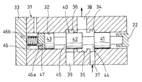
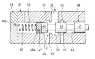
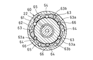
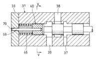
- the longitudinal cross-sectional view which shows an example of use of the spool valve concerning this invention roughly 1 is a cross-sectional view of the spool valve shown in FIG. Sectional view of the spool valve displaced to the low speed side Sectional drawing which shows the other example of the spool valve which concerns on this invention Sectional view along line III-III in FIG. 3A Sectional drawing which shows other examples of spool rotation stopper Sectional view along line IV-IV in FIG. 4A Sectional drawing which shows the further another example of the rotation stopper of a spool Sectional view along line VV in FIG.
- the sleeve valve according to the present invention includes an electric motor unit 10, a motion conversion mechanism unit 20 that converts rotational motion into linear motion, and a hydraulic control unit 30.
- the electric motor unit 10 includes a motor case 11 and an electric motor 12 housed therein.
- the rotating shaft 12a of the electric motor 12 passes through the end plate 11a of the motor case 11 and It faces a nut case 28 (described later) connected to the end.
- the motion conversion mechanism unit 20 includes a ball screw 21 and a nut case 28 that covers the ball screw 21.
- the ball screw 21 includes a screw shaft 22 having a screw groove 23 formed on the outer periphery, a nut 24 fitted outside the screw shaft 22, a screw groove 25 formed on the inner periphery of the nut 24, and the screw shaft 22.
- the nut 24 is fitted into the open end of a cylindrical nut holder 27 having a closed end, and can be rotated integrally with the nut holder 27. Yes.
- the nut holder 27 is connected to the rotating shaft 12 a of the electric motor 12 and is driven to rotate by the electric motor 12.
- the nut 24 and the nut holder 27 are entirely covered by the nut case 28 connected to the motor case 11, and are rotatably supported by a pair of rolling bearings 29 incorporated in both ends of the nut case 28.
- the hydraulic control unit 30 has a valve body 31 connected to the end of the nut case 28.
- a spool insertion hole 32 that penetrates from one end to the other end is formed in the valve body 31, and the tip of the spool insertion hole 32 is closed by an end plate 33 connected to the valve body 31.
- the first circumferential groove 34, the second circumferential groove 35, and the third circumferential groove 36 are provided in order from the ball screw 21 side on the inner diameter surface of the spool insertion hole 32.
- an input port 37 that communicates with the first circumferential groove 34, an output port 38 that communicates with the second circumferential groove 35, and a drain port 39 that communicates with the third circumferential groove 36 are provided. .
- a shaft-like spool 40 is inserted into the spool insertion hole 32.
- One end of the spool 40 is connected to the screw shaft 22 of the ball screw 21 so as not to rotate relative to the ball screw 21, and is movable in the axial direction integrally with the screw shaft 22.
- the spool 40 is provided with a first land 41, a second land 42, and a third land 43 slidable along the inner diameter surface of the spool insertion hole 32 in order from the end on the screw shaft 22 side.
- a groove-shaped first oil passage 44 is provided between the land 41 and the second land 42.
- a second oil passage 45 is provided between the second land 42 and the third land 43.
- the first oil passage 44 is connected to the input port 37 and the output.
- 38 and the second oil passage 45 is movable between a second position (low speed side position) where the output port 38 and the drain port 39 communicate with each other.
- the elastic member 46 that urges the spool 40 toward the low speed side position is incorporated in the closed end of the spool insertion hole 32.
- the elastic member 46 is formed of a compression coil spring, and bent portions 46a and 46b facing in the axial direction are provided at both ends thereof. The other bent piece 46 b is locked to the end plate 33 of the valve body 31 to prevent the spool 40 and the screw shaft 22 from rotating.
- the spool valve shown in the embodiment has the above-described structure, and adopts the spool valve, for example, to hydraulically control the gear ratio switching cylinder S of the V-belt type continuously variable transmission (CVT) shown in FIG. If the input port 37 and the oil pump P discharge ports communicating with an oil passage T 1, the output port 38 and the V-belt type fix pulley 52 slides pulley 51 forming a drive pulley 50 of the continuously variable transmission (CVT) communicating with the oil passage T 2 a sheet-oil outlet of the cylinder S is moved toward the.
- CVT continuously variable transmission
- the winding diameter of the V belt 53 applied to the driving pulley 50 and the winding diameter of the V belt 53 applied to the driven pulley 54 by the movement of the slide pulley 51 relative to the fixed pulley 52 are determined. It is made to change and the gear ratio is changed.
- FIG. 1 shows a state where the spool 40 of the spool valve is located at the neutral position, and the input port 37 and the output port 38 and the output port 38 and the drain port 39 are blocked by the spool 40.
- the input port 37 and the output port 38 are connected via the first oil passage 44 of the spool 40 as shown in FIG. 2A.
- the second land shuts off the output port 38 and the drain port 39, the oil discharged from the oil pump P is sent into the cylinder S, and the slide pulley 51 that forms the drive pulley 50 is connected to the fixed pulley 52.
- the drive pulley 50 is shifted toward the high speed side.
- FIG. 1 shows a state in which the spool 40 is returned to the neutral position. In the neutral position, the input port 37 and the output port 38, and the output port 38 and the drain port 39 are blocked by the second land 42 of the spool 40, The V-belt continuously variable transmission (CVT) maintains constant speed.
- the input port 37 and the output port 38 are shut off, and the output port 38 and the drain port 39 communicate with each other, so that the oil in the cylinder S is discharged from the output port 38 to the drain port 39.
- the oil is moved, the slide pulley 51 of the drive pulley 50 moves in a direction away from the fixed pulley 52, and the drive pulley 50 is shifted to the low speed side.
- the drive pulley 50 is shifted to the low speed side, so that the vehicle is in a decelerating running state, and the impact applied from the vehicle to the driver is small. Compared with the case where the pulley 50 is shifted to the high speed side, it is superior in terms of safety.
- the spool screw 40 is moved in the axial direction by operating the ball screw 21 by driving the electric motor 12. The amount of movement can be increased. Then, by increasing the movement amount of the spool 40, the input port 37, the output port 38, the drain port 39, and the oil passages T 1 and T 2 connected to the respective ports can be increased in cross-sectional area. In addition, the responsiveness at the time of shifting of the V-belt type continuously variable transmission (CVT) can be improved.
- CVT continuously variable transmission
- the screw shaft 22 is moved in the axial direction by the rotation of the nut 24 forming the ball screw 21, but as shown in FIG. 3A, the screw shaft 22a is screwed onto the rotary shaft 12a of the electric motor 12.
- the shaft 22 may be connected, and the nut 24 may be moved in the axial direction by rotating the screw shaft 22.
- the nut 24 is prevented from rotating by the linear ball bearing 60, is supported so as to be movable in the axial direction, and is bent as an elastic member 46 that urges the spool 40 toward the low speed side position.
- the compression coil spring which does not have 46a and 46b is employ
- a cage 62 is incorporated inside the outer ring 61 that is press-fitted into the inner diameter surface of the nut case 28, and a plurality of oval guide grooves 63 are provided around the cage 62.
- An interval is provided in the direction, and one linear track portion 63a of the pair of parallel linear track portions 63a and 63b of the guide groove 63 is formed as a long hole that opens at the inner diameter surface of the cage.
- a large number of balls 64 are incorporated in the guide groove 63, and the balls 64 are allowed to roll along the rolling surface 65 formed on the inner diameter surface of the outer ring 61.
- the nut 64 protrudes inward from the inner diameter surface of the retainer 62, and the ball 64 is allowed to roll along a linear groove 66 formed on the outer periphery of the nut 24 so that the nut 24 is supported movably and is prevented from rotating. .
- the elastic member 46 prevents the screw shaft 22 that is linearly driven of the ball screw 21 from rotating, whereas in FIGS. 3A and 3B, the nut 24 that is linearly driven by the ball screw 21 is prevented from rotating by the linear ball bearing 60.
- the detent means is not limited to this.
- FIGS. 4A, 4B, 5A, and 5B show another example of the rotation preventing means for the screw shaft 22 or the nut 24 that is linearly driven by the ball screw 21.
- a guide pin 67 protrudes at an eccentric position of the front end surface of the spool 40, and the guide pin 67 is slidably inserted into a pin hole 68 formed in the end plate 33 of the valve body 31.
- the spool 40 is prevented from rotating, and the screw shaft 22 or the nut 24 that moves the spool 40 in the axial direction is prevented from rotating.
- a guide pin 69 having a non-circular cross section is provided at the center of the front end surface of the spool 40, and the guide pin 69 is inserted into a non-circular pin hole 70 formed on the end plate 33 of the valve body 31.
- the spool 40 is slidably inserted to prevent the spool 40 from rotating, and the screw shaft 22 or the nut 24 that moves the spool 40 in the axial direction is prevented from rotating.
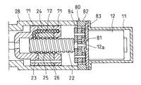
- a top type circulation system for the ball 26 in the ball screw 21 is adopted, but a pair of end caps 71 are connected to both ends of the nut 24 as shown in FIG.
- an end cap type may be used in which a circulation path 72 is formed in each of the end cap 71 and the nut 24 to circulate the ball 26.
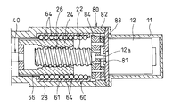
- FIG. 7A and 7B show another embodiment of the spool valve.
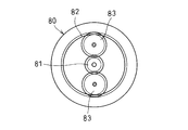
- This embodiment is different from the spool valve shown in FIG. 1 in that the rotation of the rotating shaft 12a of the electric motor 12 is reduced by the planetary gear type reduction mechanism 80 and the nut 24 is rotated. For this reason, the same parts as those in the spool valve shown in FIG.
- the planetary gear type reduction mechanism 80 includes a sun gear 81 attached to the rotating shaft 12 a of the electric motor 12, a fixed ring gear 82 incorporated between opposing portions of the nut case 28 and the motor case 11, and the ring gear 82. And a pinion gear 83 that meshes with both the sun gear 81 and a nut holder 27 as a carrier that supports the pinion gear 83.
- the nut 24 supported by the motor 27 is rotated at a reduced speed.
- a small-sized electric motor 12 having a small capacity can be adopted.
- the axial length of the spool valve can be made compact.
- reference numeral 84 denotes a carrier that rotatably supports the pinion gear 83.
- the carrier 84 is fixed to the screw shaft 22 and rotates integrally with the screw shaft 22.
- FIG. 10 shows still another example of the spool valve according to the present invention.
- the electric motor 12 is arranged in parallel with the screw shaft 22 of the ball screw 21, and the rotation of the rotating shaft 12 a of the electric motor 12 is transmitted to the nut 24 of the ball screw 21 via the spur gear type reduction mechanism 85. Yes.
- the electric motor 12 and the ball screw 21 are accommodated in a single case 86, and a guide cylinder 87 is incorporated coaxially with the screw shaft 22 in a case portion covering the ball screw 21, and is arranged on the inner periphery of the guide cylinder 87.
- a guide pin 89 provided on the screw shaft 22 is slidably inserted into the formed axial guide groove 88 to prevent the screw shaft 22 from rotating.
- the other parts are the same as those of the spool valve shown in FIG. 1, and the same parts are denoted by the same reference numerals and the description thereof is omitted.
- the electric motor 12 is arranged in parallel with the ball screw 21, and the rotation of the electric motor 12 is reduced by the spur gear reduction mechanism 85 and transmitted to the nut 24 of the ball screw 21.
- the axial length of the spool valve can be made more compact.
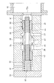
- FIG. 11 shows still another example of the spool valve according to the present invention.
- a ball screw 21 that converts rotation of the rotary shaft 12a of the electric motor 12 into linear motion is incorporated into a spool insertion hole 32 formed in the valve body 31, and the screw shaft 22 is connected to the rotary shaft 12a.
- a nut 24 that is screw-engaged with the screw shaft 22 via a ball 26 is used as a spool, and the first land 41 to the third land 43 are formed on the nut 24 as well as the spool 40 shown in FIG.
- a first oil passage 44 and a second oil passage 45 are formed between the lands.
- a guide pin 90 is provided on the outer periphery of the nut 24 as a spool, and the guide pin 90 is slidably inserted into an axial groove 91 formed on the inner periphery of the spool insertion hole 32 to prevent the nut 24 from rotating. And slidable support.
- the spool valve can be made more compact in the axial direction.
Landscapes
- Engineering & Computer Science (AREA)
- General Engineering & Computer Science (AREA)
- Mechanical Engineering (AREA)
- Chemical & Material Sciences (AREA)
- Combustion & Propulsion (AREA)
- Transportation (AREA)
- Physics & Mathematics (AREA)
- Fluid Mechanics (AREA)
- Electrically Driven Valve-Operating Means (AREA)
- Mechanically-Actuated Valves (AREA)
- Transmission Devices (AREA)
- Multiple-Way Valves (AREA)
Abstract
L'invention concerne un distributeur à tiroir cylindrique qui peut apporter des avantages en termes de réponse et de sécurité améliorées pour un équipement à commande hydraulique tel que des transmissions à variation continue du type à courroie en V. Un tiroir (40) est installé dans un trou d'insertion de tiroir (32) formé dans un corps de soupape (31). Le tiroir (40) est déplacé, au moyen d'un moteur électrique (12) et d'une vis sphérique (21), jusqu'à une première position dans laquelle un orifice d'entrée (37) et un port de sortie (38) sont en communication, au moment où l'orifice de sortie (38) et un orifice de drainage (39) sont fermés l'un par rapport à l'autre, et est déplacé jusqu'à une seconde position dans laquelle l'orifice d'entrée (37) et l'orifice de sortie (38) sont fermés l'un par rapport à l'autre, au moment où l'orifice de sortie (38) et l'orifice de drainage (39) sont en communication.
Priority Applications (3)
| Application Number | Priority Date | Filing Date | Title |
|---|---|---|---|
| US15/500,303 US10794483B2 (en) | 2014-07-31 | 2015-07-17 | Spool valve |
| CN201580036609.7A CN106662266B (zh) | 2014-07-31 | 2015-07-17 | 滑阀 |
| EP15826598.3A EP3176479B1 (fr) | 2014-07-31 | 2015-07-17 | Distributeur à tiroir cylindrique |
Applications Claiming Priority (2)
| Application Number | Priority Date | Filing Date | Title |
|---|---|---|---|
| JP2014-156595 | 2014-07-31 | ||
| JP2014156595A JP6400372B2 (ja) | 2014-07-31 | 2014-07-31 | スプールバルブ |
Publications (1)
| Publication Number | Publication Date |
|---|---|
| WO2016017458A1 true WO2016017458A1 (fr) | 2016-02-04 |
Family
ID=55217362
Family Applications (1)
| Application Number | Title | Priority Date | Filing Date |
|---|---|---|---|
| PCT/JP2015/070546 Ceased WO2016017458A1 (fr) | 2014-07-31 | 2015-07-17 | Distributeur à tiroir cylindrique |
Country Status (5)
| Country | Link |
|---|---|
| US (1) | US10794483B2 (fr) |
| EP (1) | EP3176479B1 (fr) |
| JP (1) | JP6400372B2 (fr) |
| CN (1) | CN106662266B (fr) |
| WO (1) | WO2016017458A1 (fr) |
Cited By (4)
| Publication number | Priority date | Publication date | Assignee | Title |
|---|---|---|---|---|
| WO2016140162A1 (fr) * | 2015-03-03 | 2016-09-09 | Ntn株式会社 | Soupape de commande hydraulique |
| WO2018051881A1 (fr) * | 2016-09-15 | 2018-03-22 | Ntn株式会社 | Actionneur électrique |
| US20220290745A1 (en) * | 2019-09-02 | 2022-09-15 | Safran Electronics & Defense Actuation | Reverse multi-track ball screw |
| CN116220611A (zh) * | 2023-02-06 | 2023-06-06 | 江苏苏盐阀门机械有限公司 | 一种防腐蚀油井阀门 |
Families Citing this family (19)
| Publication number | Priority date | Publication date | Assignee | Title |
|---|---|---|---|---|
| JP6877175B2 (ja) * | 2017-02-21 | 2021-05-26 | 川崎重工業株式会社 | スプール弁 |
| JP7146369B2 (ja) * | 2017-03-29 | 2022-10-04 | Ntn株式会社 | 電動アクチュエータおよび電動アクチュエータの製造方法 |
| JP6955405B2 (ja) * | 2017-09-12 | 2021-10-27 | 川崎重工業株式会社 | スプール弁装置、及びスプール弁 |
| DE102017125819A1 (de) * | 2017-11-06 | 2019-05-09 | Kiekert Ag | Stellantrieb für kraftfahrzeugtechnische Anwendungen |
| JP7037370B2 (ja) * | 2018-01-12 | 2022-03-16 | 川崎重工業株式会社 | スプール弁 |
| WO2019155932A1 (fr) * | 2018-02-09 | 2019-08-15 | キヤノン電子株式会社 | Électrovanne |
| US11408531B2 (en) | 2018-05-17 | 2022-08-09 | Kawasaki Jukogyo Kabushiki Kaisha | Spool valve |
| KR102726554B1 (ko) * | 2018-11-02 | 2024-11-06 | 주식회사 대동 | 수동 절환식 플로팅 밸브 |
| CN112996982B (zh) * | 2018-11-09 | 2023-10-27 | 芙罗服务管理公司 | 流体交换设备以及相关系统和方法 |
| CN111765269B (zh) * | 2019-04-01 | 2021-08-24 | 浙江盾安禾田金属有限公司 | 切换阀及具有其的制冷系统 |
| CN110388478A (zh) * | 2019-07-03 | 2019-10-29 | 中国石油集团渤海钻探工程有限公司 | 流体控制器 |
| CN110296118B (zh) * | 2019-08-05 | 2024-04-02 | 安徽理工大学 | 一种应用于双自由度转阀阀芯的自动切换结构 |
| CN110886655A (zh) * | 2019-11-22 | 2020-03-17 | 中国航发西安动力控制科技有限公司 | 用于航空发动机加力燃油系统的活门 |
| EP3835625B1 (fr) | 2019-12-09 | 2024-08-07 | Ningbo Geely Automobile Research & Development Co. Ltd. | Système d'actionneur pour une transmission de véhicule, véhicule comprenant un système d'actionneur et procédé de fonctionnement d'un système d'actionneur |
| JP2021148215A (ja) * | 2020-03-19 | 2021-09-27 | 株式会社鷺宮製作所 | 電動弁および冷凍サイクルシステム |
| CA3138135C (fr) * | 2021-01-05 | 2026-03-17 | The Boeing Company | Assemblage de bobine de selecteur de circuit |
| CN113915376B (zh) * | 2021-11-04 | 2024-04-30 | 哈尔滨工业大学 | 一种数字阀的传动转换器 |
| CN116498613B (zh) * | 2023-04-13 | 2025-08-12 | 杭州玖清科技有限公司 | 一种面向清洁能源精准压缩用的电液伺服流量阀 |
| WO2024254837A1 (fr) | 2023-06-16 | 2024-12-19 | Sharkninja Operating Llc | Buses de mélange de carbonatation |
Citations (5)
| Publication number | Priority date | Publication date | Assignee | Title |
|---|---|---|---|---|
| JPS6175563U (fr) * | 1984-10-24 | 1986-05-21 | ||
| JPH08193668A (ja) * | 1995-01-12 | 1996-07-30 | Nippon Beeles- Kk | 電動式調節弁駆動用リニアアクチュエータ |
| JP2000028023A (ja) * | 1998-07-15 | 2000-01-25 | Ube Ind Ltd | ボールねじ駆動の油圧制御弁 |
| JP2000220760A (ja) * | 1999-02-03 | 2000-08-08 | Saginomiya Seisakusho Inc | 電動式コントロールバルブ |
| JP2009058013A (ja) * | 2007-08-30 | 2009-03-19 | Aisin Aw Co Ltd | 電磁弁 |
Family Cites Families (15)
| Publication number | Priority date | Publication date | Assignee | Title |
|---|---|---|---|---|
| US2738684A (en) * | 1949-10-21 | 1956-03-20 | Mansfield Dev Inc | Operating mechanism for high pressure valves |
| US2966891A (en) * | 1958-11-04 | 1961-01-03 | John G Williams | Simplified power relay assembly |
| DE2141519A1 (de) | 1971-08-19 | 1973-02-22 | Kloeckner Humboldt Deutz Ag | Motorantrieb fuer steuerorgane |
| JPH0665912B2 (ja) | 1984-08-28 | 1994-08-24 | 宇部興産株式会社 | 流量制御弁 |
| JPS6175563A (ja) | 1985-09-20 | 1986-04-17 | Hitachi Ltd | 固体撮像素子 |
| US5005442A (en) * | 1987-12-11 | 1991-04-09 | Aisin Aw Co., Ltd. | Control system for stepless belt transmissions |
| US4951549A (en) * | 1988-12-12 | 1990-08-28 | Olsen Controls, Inc. | Digital servo valve system |
| DE4131500A1 (de) * | 1991-09-21 | 1993-03-25 | Bosch Gmbh Robert | Elektromagnetisch betaetigbares einspritzventil |
| US7066189B2 (en) * | 2002-12-20 | 2006-06-27 | Control Components, Inc. | Predictive maintenance and initialization system for a digital servovalve |
| US20110023513A1 (en) * | 2009-07-28 | 2011-02-03 | Hamilton Sundstrand Corporation | Expansion valve for a refrigerant system |
| US8636262B2 (en) * | 2009-11-13 | 2014-01-28 | Fisher Controls International, Llc | Coupling apparatus for use with electric actuators |
| JP5666174B2 (ja) * | 2010-06-11 | 2015-02-12 | ナブテスコ株式会社 | 多連方向切換弁 |
| US9518672B2 (en) * | 2010-06-21 | 2016-12-13 | Cameron International Corporation | Electronically actuated gate valve |
| EP2832596B1 (fr) | 2012-03-30 | 2017-04-19 | Honda Motor Co., Ltd. | Dispositif de freinage |
| CN203477484U (zh) | 2013-09-02 | 2014-03-12 | 上海开维喜阀门集团有限公司 | 超低温轴流式止回阀 |
-
2014
- 2014-07-31 JP JP2014156595A patent/JP6400372B2/ja not_active Expired - Fee Related
-
2015
- 2015-07-17 WO PCT/JP2015/070546 patent/WO2016017458A1/fr not_active Ceased
- 2015-07-17 US US15/500,303 patent/US10794483B2/en not_active Expired - Fee Related
- 2015-07-17 CN CN201580036609.7A patent/CN106662266B/zh not_active Expired - Fee Related
- 2015-07-17 EP EP15826598.3A patent/EP3176479B1/fr not_active Not-in-force
Patent Citations (5)
| Publication number | Priority date | Publication date | Assignee | Title |
|---|---|---|---|---|
| JPS6175563U (fr) * | 1984-10-24 | 1986-05-21 | ||
| JPH08193668A (ja) * | 1995-01-12 | 1996-07-30 | Nippon Beeles- Kk | 電動式調節弁駆動用リニアアクチュエータ |
| JP2000028023A (ja) * | 1998-07-15 | 2000-01-25 | Ube Ind Ltd | ボールねじ駆動の油圧制御弁 |
| JP2000220760A (ja) * | 1999-02-03 | 2000-08-08 | Saginomiya Seisakusho Inc | 電動式コントロールバルブ |
| JP2009058013A (ja) * | 2007-08-30 | 2009-03-19 | Aisin Aw Co Ltd | 電磁弁 |
Cited By (6)
| Publication number | Priority date | Publication date | Assignee | Title |
|---|---|---|---|---|
| WO2016140162A1 (fr) * | 2015-03-03 | 2016-09-09 | Ntn株式会社 | Soupape de commande hydraulique |
| WO2018051881A1 (fr) * | 2016-09-15 | 2018-03-22 | Ntn株式会社 | Actionneur électrique |
| US20220290745A1 (en) * | 2019-09-02 | 2022-09-15 | Safran Electronics & Defense Actuation | Reverse multi-track ball screw |
| US12331814B2 (en) * | 2019-09-02 | 2025-06-17 | Safran Electronics & Defense Actuation | Reverse multi-track ball screw |
| CN116220611A (zh) * | 2023-02-06 | 2023-06-06 | 江苏苏盐阀门机械有限公司 | 一种防腐蚀油井阀门 |
| CN116220611B (zh) * | 2023-02-06 | 2023-09-01 | 江苏苏盐阀门机械有限公司 | 一种防腐蚀油井阀门 |
Also Published As
| Publication number | Publication date |
|---|---|
| EP3176479A4 (fr) | 2017-07-19 |
| EP3176479B1 (fr) | 2018-10-31 |
| JP6400372B2 (ja) | 2018-10-03 |
| US20170211699A1 (en) | 2017-07-27 |
| CN106662266B (zh) | 2020-03-06 |
| JP2016033400A (ja) | 2016-03-10 |
| EP3176479A1 (fr) | 2017-06-07 |
| US10794483B2 (en) | 2020-10-06 |
| CN106662266A (zh) | 2017-05-10 |
Similar Documents
| Publication | Publication Date | Title |
|---|---|---|
| JP6400372B2 (ja) | スプールバルブ | |
| US4560369A (en) | Belt type continuous reduction gear mechanism | |
| JP5260698B2 (ja) | 切換弁を備える内燃機関 | |
| JP4745305B2 (ja) | ベルト式無段変速機の潤滑装置 | |
| KR101302326B1 (ko) | 자동 변속기 | |
| JP4775362B2 (ja) | スプール弁 | |
| WO2012063522A1 (fr) | Transmission à variation continue du type à courroie | |
| US10746234B2 (en) | Automatic transmission | |
| KR101292623B1 (ko) | 마모 보상 기능을 갖는 클러치 액츄에이터 | |
| CN104956131B (zh) | 活塞滑阀 | |
| US5187995A (en) | Shift control system for continuously variable traction roller transmission | |
| JP5759105B2 (ja) | 油圧制御弁 | |
| JP2015007462A (ja) | Vベルト式無段変速機 | |
| JP2008185111A (ja) | 油圧式無断変速装置 | |
| ITTO960941A1 (it) | Cambio di velocita' a variazione continua | |
| JPS58207561A (ja) | 自動変速プ−リ | |
| JP2018044585A (ja) | 油圧制御装置 | |
| JP3618260B2 (ja) | 作業機の操向装置 | |
| JP5181992B2 (ja) | ベルト式無段変速機の変速制御装置 | |
| KR101804264B1 (ko) | 무단변속장치 | |
| JP2018044584A (ja) | 油圧制御装置 | |
| KR20080044057A (ko) | 통합형 스위칭 윤활방향 밸브 | |
| JPH05330441A (ja) | 動力舵取装置の操舵力制御装置 | |
| DE1051092B (de) | Nach dem Verdraengerprinzip arbeitendes leistungsteilendes hydrostatisches Getriebe | |
| JPH07332451A (ja) | トロイダル型無段変速機の変速比制御装置 |
Legal Events
| Date | Code | Title | Description |
|---|---|---|---|
| 121 | Ep: the epo has been informed by wipo that ep was designated in this application |
Ref document number: 15826598 Country of ref document: EP Kind code of ref document: A1 |
|
| WWE | Wipo information: entry into national phase |
Ref document number: 15500303 Country of ref document: US |
|
| NENP | Non-entry into the national phase |
Ref country code: DE |
|
| REEP | Request for entry into the european phase |
Ref document number: 2015826598 Country of ref document: EP |
|
| WWE | Wipo information: entry into national phase |
Ref document number: 2015826598 Country of ref document: EP |