EP3176907B1 - Contrôleur et procédé de gestion d'énergie, et programme associé - Google Patents
Contrôleur et procédé de gestion d'énergie, et programme associé Download PDFInfo
- Publication number
- EP3176907B1 EP3176907B1 EP14898422.2A EP14898422A EP3176907B1 EP 3176907 B1 EP3176907 B1 EP 3176907B1 EP 14898422 A EP14898422 A EP 14898422A EP 3176907 B1 EP3176907 B1 EP 3176907B1
- Authority
- EP
- European Patent Office
- Prior art keywords
- power
- display
- measured
- energy management
- power line
- Prior art date
- Legal status (The legal status is an assumption and is not a legal conclusion. Google has not performed a legal analysis and makes no representation as to the accuracy of the status listed.)
- Active
Links
Images





Classifications
-
- H—ELECTRICITY
- H02—GENERATION; CONVERSION OR DISTRIBUTION OF ELECTRIC POWER
- H02J—ELECTRIC POWER NETWORKS; CIRCUIT ARRANGEMENTS OR SYSTEMS FOR SUPPLYING OR DISTRIBUTING ELECTRIC POWER; SYSTEMS FOR STORING ELECTRIC ENERGY
- H02J13/00—Circuit arrangements for providing remote monitoring or remote control of equipment in a power distribution network
- H02J13/18—Circuit arrangements for providing remote monitoring or remote control of equipment in a power distribution network characterised by the remotely-controlled equipment, e.g. converters or transformers
- H02J13/333—Circuit arrangements for providing remote monitoring or remote control of equipment in a power distribution network characterised by the remotely-controlled equipment, e.g. converters or transformers the equipment forming part of substations
-
- H—ELECTRICITY
- H02—GENERATION; CONVERSION OR DISTRIBUTION OF ELECTRIC POWER
- H02J—ELECTRIC POWER NETWORKS; CIRCUIT ARRANGEMENTS OR SYSTEMS FOR SUPPLYING OR DISTRIBUTING ELECTRIC POWER; SYSTEMS FOR STORING ELECTRIC ENERGY
- H02J13/00—Circuit arrangements for providing remote monitoring or remote control of equipment in a power distribution network
-
- H—ELECTRICITY
- H02—GENERATION; CONVERSION OR DISTRIBUTION OF ELECTRIC POWER
- H02J—ELECTRIC POWER NETWORKS; CIRCUIT ARRANGEMENTS OR SYSTEMS FOR SUPPLYING OR DISTRIBUTING ELECTRIC POWER; SYSTEMS FOR STORING ELECTRIC ENERGY
- H02J13/00—Circuit arrangements for providing remote monitoring or remote control of equipment in a power distribution network
- H02J13/10—Circuit arrangements for providing remote monitoring or remote control of equipment in a power distribution network characterised by displaying of information or by user interaction, e.g. supervisory control and data acquisition [SCADA] systems
-
- H—ELECTRICITY
- H02—GENERATION; CONVERSION OR DISTRIBUTION OF ELECTRIC POWER
- H02J—ELECTRIC POWER NETWORKS; CIRCUIT ARRANGEMENTS OR SYSTEMS FOR SUPPLYING OR DISTRIBUTING ELECTRIC POWER; SYSTEMS FOR STORING ELECTRIC ENERGY
- H02J7/00—Circuit arrangements for charging or discharging batteries or for supplying loads from batteries
- H02J7/865—Battery or charger load switching, e.g. concurrent charging and load supply
-
- G—PHYSICS
- G01—MEASURING; TESTING
- G01R—MEASURING ELECTRIC VARIABLES; MEASURING MAGNETIC VARIABLES
- G01R21/00—Arrangements for measuring electric power or power factor
- G01R21/133—Arrangements for measuring electric power or power factor by using digital technique
-
- Y—GENERAL TAGGING OF NEW TECHNOLOGICAL DEVELOPMENTS; GENERAL TAGGING OF CROSS-SECTIONAL TECHNOLOGIES SPANNING OVER SEVERAL SECTIONS OF THE IPC; TECHNICAL SUBJECTS COVERED BY FORMER USPC CROSS-REFERENCE ART COLLECTIONS [XRACs] AND DIGESTS
- Y02—TECHNOLOGIES OR APPLICATIONS FOR MITIGATION OR ADAPTATION AGAINST CLIMATE CHANGE
- Y02E—REDUCTION OF GREENHOUSE GAS [GHG] EMISSIONS, RELATED TO ENERGY GENERATION, TRANSMISSION OR DISTRIBUTION
- Y02E10/00—Energy generation through renewable energy sources
- Y02E10/50—Photovoltaic [PV] energy
- Y02E10/56—Power conversion systems, e.g. maximum power point trackers
-
- Y—GENERAL TAGGING OF NEW TECHNOLOGICAL DEVELOPMENTS; GENERAL TAGGING OF CROSS-SECTIONAL TECHNOLOGIES SPANNING OVER SEVERAL SECTIONS OF THE IPC; TECHNICAL SUBJECTS COVERED BY FORMER USPC CROSS-REFERENCE ART COLLECTIONS [XRACs] AND DIGESTS
- Y04—INFORMATION OR COMMUNICATION TECHNOLOGIES HAVING AN IMPACT ON OTHER TECHNOLOGY AREAS
- Y04S—SYSTEMS INTEGRATING TECHNOLOGIES RELATED TO POWER NETWORK OPERATION, COMMUNICATION OR INFORMATION TECHNOLOGIES FOR IMPROVING THE ELECTRICAL POWER GENERATION, TRANSMISSION, DISTRIBUTION, MANAGEMENT OR USAGE, i.e. SMART GRIDS
- Y04S10/00—Systems supporting electrical power generation, transmission or distribution
- Y04S10/40—Display of information, e.g. of data or controls
Definitions
- the present disclosure relates to an energy management controller, an energy management method and a program.
- JP2014039362A provides an energy management device, energy management method, and energy management system, capable of presenting information with high reliability, using a plurality of power values measured by respective apparatuses by a communication section that acquires a generated power value of a distributed power supply for supplying electric power that can be sold and a power value of power sold to a system, and a control section that, based on either one of the generated power value and the power value of sold power, corrects the other power value.
- Patent Literature 1 Unexamined Japanese Patent Application Kokai Publication No. 2013-210288
- HEMS home energy management systems
- EV-PCS electric vehicle power conditioning system
- the EV-PCS is required to measure power values from a plurality of power lines within the home in order to control charging and discharging of a storage battery installed in the electric vehicle.
- the HEMS also uses a power measurement device to measure power values from the plurality of power lines within the home.
- the power value for the single power line may possibility be measured by both the EV-PCS and the HEMS.
- a controller included in the HEMS is able to select one power value, which is more appropriate, and if that power value can be used for energy management within the home, then advantages can be anticipated, such as the providing of accurate state of use of power, achievement of accurate operation control of the control target device, and the like.
- the object of the present disclosure is to provide an energy management controller and the like capable of performing power management and the like by selection of an optimum power value from among a plurality of power values measured from a single power line.
- the energy management controller of the present disclosure includes:
- management and the like of power is enabled by selection of an optimum power value from among a plurality of power values measured from a single power line.
- FIG. 1 is a diagram showing an overall configuration of an energy management system 1 according to an Embodiment 1 of the present disclosure.
- This energy management system 1 is a so-called home energy management system (HEMS) for managing power used in an ordinary home.
- the energy management system 1 includes an energy management controller 2, an operation terminal 3, a power measurement device 4, an EV-PCS 5, a PV-PCS 6, and a plurality of control target devices 7 (control target device 7a, 7b, and the like).
- HEMS home energy management system
- the energy management controller 2 which is installed at a suitable location within a home H, displays a consumption state of power by monitoring power consumed in the home (demand area). Moreover, the energy management controller 2 performs actions such as operation control, monitoring of the operations state and the like of each control target device 7. The energy management controller 2 is described below in detail.
- the operation terminal 3 includes an input device such as a touch panel, a touch pad or the like, a display device such as a liquid crystal display, and a communication interface.
- the operation terminal 3 performs data communication with the energy management controller 2 based on a widely-known wireless LAN, standard such as Wi-Fi (registered trademark).
- the operation terminal 3 functions as an interface (user interface) between the energy management system 1 and the user, who is a resident of the home H.
- the power measurement device 4 measures a value of power transmitted through each of a plurality of power lines D1, D2 and D3 in this home (demand area).
- the power line D1 is arranged between a commercial power supply 8 and the EV-PCS 5;
- the power line D2 is arranged between the EV-PCS 5 and a distribution board 9;
- the power line D3 is arranged between the PV-PCS 6 and the EV-PCS 5.
- the power measurement device 4 is connected through a communication line to a current transformer (CT) 1 connected to the power line D1, is connected through a communication line to a current transformer (CT) 2 connected to the power line D2, and is connected through a communication line to a current transformer (CT) 3 connected to the power line D3.
- CTs 1, 2 and 3 are sensors for measurement of alternating current.
- the power measurement device 4 measures the power value from the power line D1 based on the measurement results of the CT 1.
- the power measurement device 4 measures the power value from the power line D2 based on the measurement results of the CT 2, and measures the power value from the power line D3 based on the measurement results of the CT 3.
- the power measurement device 4 includes a wireless communication interface and is connected through a wireless network (not illustrated) constructed in the home H to enable communication with the energy management controller 2.
- This wireless network is based on a communication protocol such as ECHONET Lite.
- the power measurement device 4 In response to a request from the energy management controller 2, the power measurement device 4 generates measurement data that includes the measured power value from the power line D1 and transmits the generated measurement data to the energy management controller 2.
- This measurement data also includes identification (ID) of the power measurement device 4, ID of the power line D1, and measurement time.
- ID of the power measurement device 4 is "10"
- the ID of the power line D1 is "01".
- the power measurement device 4 transmits to the energy management controller 2 measurement data that includes the ID of the power measurement device 4, the ID of the power line D2, the measurement time, and the measured power value from the power line D2.
- the power measurement device 4 transmits to the energy management controller 2 measurement data that includes the ID of the power measurement device 4, the ID of the power line D3, the measurement time, and the measured power value from the power line D3.
- the ID of the power line D2 is "02"
- the ID of the power line D3 is "03".
- the EV-PCS 5 is a power conditioning system used for an electric vehicle (EV) 10.
- the EV-PCS 5 performs control of charging/discharging of a storage battery 11 that is installed in the EV 10.
- the EV-PCS 5 charges the storage battery 11 using power supplied from the commercial power supply 8 and/or from the PV-PCS 6.
- the PV-PCS 6 supplies the power released from the storage battery 11 to the distribution board 9 as power for consumption in this home.
- the PV-PCS 6 supplies the power released from the storage battery 11 to the commercial power supply 8 as power for sale.
- the EV-PCS 5 measures the value of power transmitted through each of a plurality of power lines D1, D3 and D4 in this home.
- the EV-PCS 5 is connected through a communication line to the current transformer (CT) 4 connected to the power line D1, through a communication line to the current transformer (CT) 5 connected to the power line D3, and through a communication line to the current transformer (CT) 6 connected to the power line D4.
- CT current transformer
- the EV-PCS 5 measures the power value from the power line D1 based on the measurement results by the CT 4.
- the EV-PCS 5 measures the power value from the power line D3 based on the measurement results of the CT 5, and measures the power value from the power line D4 based on the measurement results of the CT 6.
- the EV-PCS 5 is connected in a communication-capable manner with the energy management controller 2 through a dedicated communication line. In response to a request from the energy management controller 2, the EV-PCS 5 generates measurement data that includes the measured power value from the power line D1 and transmits the measurement data to the energy management controller 2. This measurement data also includes the ID of the EV-PCS 5, the ID of the power line D1, and the measurement time. In the present embodiment, the ID of the EV-PCS 5 is "11".
- the EV-PCS 5 transmits to the energy management controller 2 measurement data that includes the ID of the EV-PCS 5, the ID of the power line D3, the measurement time, and the measured power value from the power line D3.
- the EV-PCS 5 transmits to the energy management controller 2 measurement data that includes the ID of the EV-PCS 5, the ID of the power line D4, the measurement time, and the measured power value from the power line D4.
- the ID of the power line D4 is "04".
- the PV-PCS 6 is a power conditioning system for photovoltaics (PV).
- the PV-PCS 6 performs, using a power conditioner, DC power to AC power conversion of electricity generated by photovoltaic panels (PV panels) 12 and supplies the converted power to the EV-PCS 5 through the power line D3.
- the power supplied from the PV-PCS 6 is supplied (for consumption) to the distribution board 9 through the EV-PCS 5, is supplied (for sale) to the commercial power supply 8, and is used for charging the storage battery 11.
- the control target devices 7 are electric appliances installed in the home H, such as a lighting apparatus, an air conditioner, a refrigerator, an induction heating (IH) cooker, a rice cooker, a microwave oven, and a floor heating system.
- the control target devices 7a, 7b and the like are connected through respective power lines D5a, D5b and the like branching from the power line D2 via the distribution board 9.
- Each control target device 7 is connected in a communication-capable manner to the energy management controller 2 through the aforementioned non-illustrated wireless network. Further, each control target device 7 may be connected to this wireless network via a non-illustrated external communication adapter.
- the energy management controller 2 includes a device communicator 20 for communication with the power measurement device 4 and each control target device 7, a terminal communicator 21 for communication with the operation terminal 3, a data memory 22 for storing programs and data, and a controller 23 for controlling these components. These components are interconnected through a bus 24.
- the device communicator 20 for example, includes a communication interface such as a wireless LAN card, is connected to the aforementioned wireless network, and under control of the control device 23, performs wireless data communication with the power measurement device 4 and each of the control target devices 7.
- a communication interface such as a wireless LAN card
- the terminal communicator 21 includes a predetermined short-distance wireless communication interface, and under the control of the controller 23, performs data communication with the operation terminal 3 based on a widely-known wireless LAN standard such as Wi-Fi (registered trademark).
- Wi-Fi registered trademark
- the data memory 22 includes a readable/writable nonvolatile semiconductor memory such as a flash memory.
- the data memory 22 stores a measurement data table 220 and a priority table 221.
- the data memory 22 stores a program for monitoring power consumed within the home, a program for control of operation of each control target device 7, and data used during execution of such programs.
- the measurement data table 220 is a data table that stores respective measurement data sent from the power measurement device 4 and the EV-PCS 5.
- the priority table 221 is a data table in which priorities of the devices measuring the single power line are defined for each power line.
- the priority table 221, as shown in FIG. 4 is a data table in which the priorities of the power measurement device 4 and the EV-PCS 5 measuring the power lines D1 and D3 are defined for each power line.
- the priority is a predetermined indicator for determination of, among the two power values measured from the single power line by the power measurement device 4 and the EV-PCS 5, which value is to be selected as the power measured from the power line.
- the power value measured by a device having a high priority in comparison to other devices is selected (is adopted) as the power value measured from the associated power line.
- the priority is determined by measurement accuracy according to specifications for each device.
- the priority may be determined based on the number of power lines that are subjected to measurement by each device. In the case of such determination, the highest priority is assigned to the device that has the greatest number of power lines that are subjected to measurement. Alternatively, the priority may be determined based upon a sampling interval of the measurement of power for each device. In the case of such determination, the highest priority is assigned to the device that has the shortest sampling interval.
- the determination of priorities in the aforementioned manner and the setting of data in the priority table 221, for example, are performed by personnel in charge of construction and the like during installation of the energy management system 1.
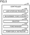
- the controller 23 includes a central processing unit (CPU), read only memory (ROM), random access memory (RAM) and the like (all non-illustrated), and performs overall control of the energy management controller 2. As shown in FIG. 5 , the controller 23, as functions specific to the present disclosure, includes a user interface processor 230, a measurement power acquirer 231, a selector 232, a power manager 233 and a power display instructor 234. The functions of these components are achieved by a CPU and the like executing programs stored in the data memory 22.
- CPU central processing unit
- ROM read only memory
- RAM random access memory
- the user interface processor 230 performs user interface processing through the operation terminal 3. That is to say, the user interface processor 230 receives the operation of the user through the operation terminal 3 and the terminal communicator 21 and performs processing according to contents of the received operation. Moreover, the user interface processor 230 transmits to the operation terminal 3, through the terminal communicator 21, information to be presented to the user, and performs processing to cause the operation terminal 3 to display such information.
- the measurement power acquirer 231 performs processing for acquisition of the measured power values from each of the devices, that is, from the power measurement device 4 and the EV-PCS 5. Specifically, the transmission of measurement data is requested at a certain time interval, such as 30-second intervals, for each of the power measurement device 4 and the EV-PCS 5. Through the device communicator 20, the measurement power acquirer 231 acquires a plurality of measurement data sent from the power measurement device 4 and the EV-PCS 5 in response to each of these requests. The measurement power acquirer 231 stores the acquired plurality of measurement data in the measurement data table 220 stored in the data memory 22.
- the selector 232 analyzes each of the measurement data acquired by the measurement power acquirer 231 and determines whether a plurality of power values is measured from a single power line. When a plurality of power values is measured from the single power line, then the selector 232 refers to the priority table 221 and selects one power value as the power value subject to use. In the present embodiment, power values are measured by a plurality of devices, that is, the power measurement device 4 and the EV-PCS 5, from the power line D1 and power line D3. The selector 232 refers to the priority table 221 and, for both the power line D1 and the power line D3, selects the power value measured by the EV-PCS 5 as the power value subject to use. The selector 232 deletes from the measurement data table 220 the measurement data relating to the non-selected power values.
- the power manager 233 controls operation of each of the control target devices 7 based on the measurement data corresponding to each power line stored in the measurement data table 220. For example, when the power value for electricity sale in the power line D1 is high, and when the power value for consumption in the power line D2 is high, electricity-conservation control is performed to cause a lowering of operating ability of all or specific control target devices 7.
- the power display instructor 234 Based on the measurement data corresponding to each of the power lines stored in the measurement data table 220, the power display instructor 234 generates screen data showing in a predetermined mode the state of use of power, including sale of electricity. Then the power display instructor 234 transmits the generated screen data to the operation terminal 3 through the user interface processor 230 and the terminal communicator 21.
- FIG. 6 is a flowchart showing a procedure of energy management processing executed by the controller 23 of the energy management controller 1. This energy management processing is executed repeatedly at a certain time interval, such as 1-second intervals.
- the measurement power acquirer 231 determines whether a certain time period, such as 30 seconds, has passed since acquisition of the previous measurement data (step S101). If the certain time period has not passed (NO in step S101), then energy management processing ends. On the other hand, if the certain time period has passed since acquisition of the previous measurement data (YES in step S101), the measurement power acquirer 231 requests the power measurement device 4 to transmit measurement data, and acquires the measurement data sent from the power measurement device 4 in response to the request (step S102).
- a certain time period such as 30 seconds
- the measurement power acquirer 231 requests the EV-PCS 5 to transmit measurement data and acquires the measurement data sent from the EV-PCS 5 in response to the request (step S103).
- the selector 232 analyzes each of the measurement data acquired by the measurement power acquirer 231 and determines whether a plurality of power values is measured from a single power line (step S104). If there exists no plurality of power values measured from a single power line (NO in step S104), then the control device 23 performs the processing of step S106. On the other hand, if there exists a plurality of power values measured from a single power line (YES in step S104), then the selector 232 refers to the priority table 221 and selects one power value as the power value subject to use (step S105). At this time, the selector 232 deletes from the measurement data table 220 the measurement data relating to the non-selected power values.
- the power manager 233 controls operation of each of the control target devices 7 based on the measurement data corresponding to each of the power lines stored in the measurement data table 220 (step S 106). Further, the power display instructor 234 generates screen data for showing the state of use of power, and by transmission to the operation terminal 3 through the user interface processor 230 and the terminal communicator 21, causes the operation terminal 3 to display the state of use of power (step S107).
- the energy management controller 2 selects the power value measured by the device assigned the highest priority as the power value subject to use.
- the user can be presented with an accurate state of use of power, and accurate operation control of each control target device 7 can be achieved.
- Embodiment 2 of the present disclosure is described below. Further, components and the like that occur in common with the Embodiment 1 are assigned the same reference signs, and description of such components is omitted.
- the energy management controller 2 selects the power values measured by the EV-PCS 5 for the power line D1 and the power line D3 as the power value subject to use. Moreover, since the only device for measurement of the power value for the power line D2 is the power measurement device 4, the power value measured by the power measurement device 4 is the power value subject to use. Further, the EV-PCS 5 is the only device for measurement of the power value for the power line D4, and thus the power value measured by the EV-PCS 5 is the power value subject to use.
- the interval of the power measurements that is, the sampling interval of power measurement, cannot be said to necessarily be the same for the power measurement device 4 and the EV-PCS 5, and even if the sampling interval is assumed to be the same, performing synchronized measurements would be difficult. In other words, a difference between measurement times occurs between the power measurement device 4 and the EV-PCS 5 as indicated in FIG. 7 .
- the energy management controller 2 of the present embodiment has functions similar to those of the energy management controller 2 of Embodiment 1, and further, has a function for correction of the aforementioned type of difference between measurement times of the power value.
- a corrector 235 is added to the controller 23 included in the energy management controller 2 of the present embodiment.
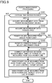
- the corrector 235 corrects the difference between the measurement times of the power values measured from each of the power lines, based on measurement data corresponding to each power line that is stored in the measurement data table 220 (step S105A of FIG. 9 ).
- the corrector 235 reads the measurement data of a predetermined time period (for example, 10 minutes) from the measurement data table 220, and detects the rise time based on each measurement data read thereby. Then the corrector 235 corrects the difference between the measurement times by comparing the detected rise times using the measurement data for the respective power lines (such as the power lines D1 and D2).
- a predetermined time period for example, 10 minutes
- the corrector 235 corrects the difference between the measurement times by comparing the detected rise times using the measurement data for the respective power lines (such as the power lines D1 and D2).
- the corrector 235 determines that a difference between the measurement times is occurring. Then the corrector 235 corrects the difference between the measurement times by matching (changing to match) the rise time of the later measurement data with the rise time of the earlier measurement data.
- the corrector 235 may read the measurement data of a predetermined time period (such as 10 minutes) from the measurement data table 220, and may correct the difference between the measurement times by executing averaging processing, over the predetermined time period, of measurement data read for each power line.
- a predetermined time period such as 10 minutes
- the difference between the measurement times of the power values measured from each of the power lines is corrected.
- the user can be presented with more accurate state of use of power, and more accurate operation control of each control target device 7 can be achieved.
- a PV-PCS 6 may measure the power value from the power line D3.
- the PV-PCS 6 is connected through a communication line with a current transformer (CT) 7 connected to the power line D3.
- CT current transformer
- the PV-PCS 6 measures the power value from the power line D3 based on the measurement results of the CT 7.
- the PV-PCS 6 is connected in a communication-capable manner with the energy management controller 2 through a dedicated communication line. In response to a request from the energy management controller 2, the PV-PCS 6 transmits to the energy management controller 2 measurement data including the measured power value from the power line D3.
- a stationary-type storage battery 13 may be added that is connected to the power line D6 by branching from the distribution board 9, and the power value for the power line D6 may be measured by each of the power measurement device 4 and the stationary-type storage battery 13.
- the power measurement device 4 connects through a communication line with a current transformer (CT) 8 connected to the power line D6, and measures the power value from the power line D6 based on the measurement results of the CT 8. In response to a request from the energy management controller 2, the power measurement device 4 transmits to the energy management controller 2 measurement data including the measured power value from the power line D6.
- the stationary-type storage battery 13 is connected through a communication line with a current transformer (CT) 9 connected to the power line D6, and measures the power value from the power line D6 based on the measurement results of the CT 9.
- CT current transformer
- the stationary-type storage battery 13 is communicatively connected through a dedicated communication line with the energy management controller 2, and in response to a request from the energy management controller 2, transmits to the energy management controller 2 measurement data including the measured power value from the power line D6.
- the power value for the power line D5a branching from the distribution board 9 may be measured by each of the power measurement device 4 and the control target device 7a.
- the power measurement device 4 connects through a communication line with a current transformer (CT) 10 connected to the power line D5a, and measures the power value from the power line D5a based on the measurement results of the CT 10.
- CT current transformer
- the power measurement device 4 transmits to the energy management controller 2 measurement data including the measured power value from the power line D5a.
- control target device 7a connects through a communication line with a current transformer (CT) 11 connected to the power line D5a, and measures the power value from the power line D5a based on the measurement results of the CT 11. In response to a request from the energy management controller 2, the control target device 7a transmits to the energy management controller 2 measurement data including the measured power value from the power line D5a.
- CT current transformer
- a program for execution by the energy management controller 2 may be stored and distributed in a computer-readable recording medium such as a compact disc read-only memory (CD-ROM), a digital versatile disc (DVD), a magneto-optical disk (MO), a universal serial bus (USB) memory and a memory card.
- a computer-readable recording medium such as a compact disc read-only memory (CD-ROM), a digital versatile disc (DVD), a magneto-optical disk (MO), a universal serial bus (USB) memory and a memory card.
- the above-described program may be stored on a disk device or the like of a server device on a communication network such as the Internet to enable the program to be downloaded to the computer, for example by superimposing the program onto a carrier wave.
- the aforementioned processing can be achieved even by execution while the program is transferred through the communication network.
- the aforementioned processing can be achieved by executing all or part of the program on the server device, and executing the program while sending and receiving by the computer the information relating to such processing through the communication network.
- the non-OS portion alone may be stored and distributed in the aforementioned recording medium, or alternatively, may be, for example, downloaded to the computer.
- the present disclosure may be used with advantage for a system and the like for management of electric power used within a household.
Landscapes
- Engineering & Computer Science (AREA)
- Power Engineering (AREA)
- Remote Monitoring And Control Of Power-Distribution Networks (AREA)
- Supply And Distribution Of Alternating Current (AREA)
- Physics & Mathematics (AREA)
- General Physics & Mathematics (AREA)
Claims (9)
- Contrôleur de gestion d'énergie (2) comprenant :un moyen d'acquisition (231) configuré de manière à acquérir, pour une pluralité de lignes électriques dans une zone de demande, à partir d'une pluralité de dispositifs (4, 5), des valeurs de puissance mesurées par la pluralité de dispositifs (4, 5), et à stocker des données connexes aux valeurs de puissance acquises, dans une mémoire (22) ;un moyen d'instruction d'affichage de puissance (234) configuré de manière à amener un écran d'affichage (3) à afficher, dans un mode prédéterminé, des informations indiquant une valeur de puissance mesurée à partir de chaque ligne électrique, et à amener l'écran d'affichage (3) à afficher des informations indiquant une valeur de puissance sélectionnée parmi une pluralité de valeurs de puissance, sur la base d'une priorité préalablement affectée à chaque dispositif (4, 5), lorsque la pluralité de valeurs de puissance est mesurée à partir d'une unique ligne électrique ; etun moyen de correction (235) configuré de manière à lire les données d'une période de temps prédéterminée à partir de la mémoire (22), à détecter un temps de montée de puissance sur la base de chacune des données lues par conséquent, et à corriger une différence entre des temps de mesure des valeurs de puissance mesurées à partir de la pluralité de lignes électriques, en comparant les temps de montée détectés en faisant appel aux données pour chaque ligne électrique.
- Contrôleur de gestion d'énergie (2) comprenant :un moyen d'acquisition (231) configuré de manière à acquérir, pour une pluralité de lignes électriques dans une zone de demande, à partir d'une pluralité de dispositifs (4, 5), des valeurs de puissance mesurées par la pluralité de dispositifs (4, 5), et à stocker des données connexes aux valeurs de puissance acquises dans une mémoire (22) ;un moyen d'instruction d'affichage de puissance (234) configuré de manière à amener un écran d'affichage (3) à afficher, dans un mode prédéterminé, des informations indiquant une valeur de puissance mesurée à partir de chaque ligne électrique, et à amener l'écran d'affichage (3) à afficher des informations indiquant une valeur de puissance sélectionnée parmi une pluralité de valeurs de puissance sur la base d'une priorité préalablement affectée à chaque dispositif (4, 5), lorsque la pluralité de valeurs de puissance est mesurée à partir d'une ligne électrique unique ; etun moyen de correction (235) configuré de manière à lire les données d'une période de temps prédéterminée, à partir de la mémoire (22), et à corriger une différence entre des temps de mesure des valeurs de puissance mesurées à partir de la pluralité de lignes électriques, en exécutant un traitement de calcul de moyenne, sur une période de temps prédéterminée, des données lues pour chaque ligne électrique.
- Contrôleur de gestion d'énergie (2) selon la revendication 1 ou 2, caractérisé en ce que :la priorité est déterminée sur la base d'une précision de mesure de chaque dispositif (4, 5) ; etla priorité la plus élevée est affectée au dispositif (4, 5) présentant la précision de mesure la plus élevée.
- Contrôleur de gestion d'énergie (2) selon la revendication 1 ou 2, caractérisé en ce que :la priorité est déterminée sur la base d'un nombre de lignes électriques qui sont soumises à une mesure par chaque dispositif (4, 5) dans la zone de demande ; etla priorité la plus élevée est affectée au dispositif (4, 5) dont le nombre de lignes électriques soumises à la mesure est le plus élevé.
- Contrôleur de gestion d'énergie (2) selon la revendication 1 ou 2, caractérisé en ce que :la priorité est déterminée sur la base d'un intervalle d'échantillonnage pour une mesure de puissance de chaque dispositif (4, 5) ; etla priorité la plus élevée est affectée au dispositif (4, 5) dont l'intervalle d'échantillonnage est le plus court.
- Procédé de gestion d'énergie comprenant les étapes ci-dessous consistant à :acquérir, par le biais d'un moyen d'acquisition (231), pour une pluralité de lignes électriques dans une zone de demande, à partir d'une pluralité de dispositifs (4, 5), des valeurs de puissance mesurées par la pluralité de dispositifs (4, 5), et stocker, par le biais d'un moyen d'acquisition (231), des données connexes aux valeurs de puissance acquises, dans une mémoire (22) ;amener, par le biais du moyen d'instruction d'affichage de puissance (234), un écran d'affichage (3) à afficher, dans un mode prédéterminé, des informations indiquant une valeur de puissance mesurée à partir de chaque ligne électrique, et amener, par le biais du moyen d'instruction d'affichage de puissance (234), l'écran d'affichage (3), à afficher des informations indiquant une valeur de puissance sélectionnée parmi une pluralité de valeurs de puissance, sur la base d'une priorité préalablement affectée à chaque dispositif (4, 5) lorsque la pluralité de valeurs de puissance est mesurée à partir d'une ligne électrique unique ; etlire, par le biais d'un moyen de correction (235), les données d'une période de temps prédéterminée, à partir de la mémoire (22), détecter, par le biais du moyen de correction (235), un temps de montée de puissance, sur la base de chacune des données lues, et corriger, par le biais du moyen de correction (235), une différence entre des temps de mesure des valeurs de puissance mesurées à partir de la pluralité de lignes électriques, en comparant les temps de montée détectés en faisant appel aux données pour chaque ligne électrique.
- Procédé de gestion d'énergie comprenant les étapes ci-dessous consistant à :acquérir, par le biais d'un moyen d'acquisition (231), pour une pluralité de lignes électriques dans une zone de demande, à partir d'une pluralité de dispositifs (4, 5), des valeurs de puissance mesurées par la pluralité de dispositifs (4, 5), et stocker, par le biais du moyen d'acquisition (231), des données connexes aux valeurs de puissance acquises, dans une mémoire (22) ;amener, par le biais du moyen d'instruction d'affichage de puissance (234), un écran d'affichage (3) à afficher, dans un mode prédéterminé, des informations indiquant une valeur de puissance mesurée à partir de chaque ligne électrique, et amener, par le biais du moyen d'instruction d'affichage de puissance (234), l'écran d'affichage (3), à afficher des informations indiquant une valeur de puissance sélectionnée parmi une pluralité de valeurs de puissance, sur la base d'une priorité préalablement affectée à chaque dispositif (4, 5) lorsque la pluralité de valeurs de puissance est mesurée à partir d'une ligne électrique unique ; etlire, par le biais du moyen de correction (235), les données d'une période de temps prédéterminée, à partir de la mémoire (22), et corriger, par le biais du moyen de correction (235), une différence entre des temps de mesure des valeurs de puissance mesurées à partir de la pluralité de lignes électriques, en exécutant un traitement de calcul de moyenne, sur une période de temps prédéterminée, des données lues pour chaque ligne électrique.
- Programme informatique comprenant des instructions qui, lorsque le programme est exécuté par un ordinateur, amènent l'ordinateur à fonctionner en tant que :un moyen d'acquisition (231) pour acquérir, pour une pluralité de lignes électriques dans une zone de demande, à partir d'une pluralité de dispositifs (4, 5), des valeurs de puissance mesurées par la pluralité de dispositifs (4, 5), et pour stocker des données connexes aux valeurs de puissance acquises, dans une mémoire (22) ;un moyen d'instruction d'affichage de puissance (234) pour amener un écran d'affichage (3) à afficher, dans un mode prédéterminé, des informations indiquant une valeur de puissance mesurée à partir de chaque ligne électrique, et pour amener l'écran d'affichage (3) à afficher des informations indiquant une valeur de puissance sélectionnée parmi une pluralité de valeurs de puissance, sur la base d'une priorité préalablement affectée à chaque dispositif (4, 5), lorsque la pluralité de valeurs de puissance est mesurée à partir d'une unique ligne électrique ; etun moyen de correction (235) pour lire les données d'une période de temps prédéterminée à partir de la mémoire (22), pour détecter un temps de montée de puissance sur la base de chacune des données lues par conséquent, et pour corriger une différence entre des temps de mesure des valeurs de puissance mesurées à partir de la pluralité de lignes électriques, en comparant les temps de montée détectés en faisant appel aux données pour chaque ligne électrique.
- Programme informatique comprenant des instructions qui, lorsque le programme est exécuté par un ordinateur, amènent l'ordinateur à fonctionner en tant que
un moyen d'acquisition (231) pour acquérir, pour une pluralité de lignes électriques dans une zone de demande, à partir d'une pluralité de dispositifs (4, 5), des valeurs de puissance mesurées par la pluralité de dispositifs (4, 5), et pour stocker des données connexes aux valeurs de puissance acquises dans une mémoire (22) ;
un moyen d'instruction d'affichage de puissance (234) pour amener un écran d'affichage (3) à afficher, dans un mode prédéterminé, des informations indiquant une valeur de puissance mesurée à partir de chaque ligne électrique, et pour amener l'écran d'affichage (3) à afficher des informations indiquant une valeur de puissance sélectionnée parmi une pluralité de valeurs de puissance sur la base d'une priorité préalablement affectée à chaque dispositif (4, 5), lorsque la pluralité de valeurs de puissance est mesurée à partir d'une ligne électrique unique ; et
un moyen de correction (235) pour lire les données d'une période de temps prédéterminée, à partir de la mémoire (22), et pour corriger une différence entre des temps de mesure des valeurs de puissance mesurées à partir de la pluralité de lignes électriques, en exécutant un traitement de calcul de moyenne, sur une période de temps prédéterminée, des données lues pour chaque ligne électrique.
Applications Claiming Priority (1)
| Application Number | Priority Date | Filing Date | Title |
|---|---|---|---|
| PCT/JP2014/069844 WO2016016931A1 (fr) | 2014-07-28 | 2014-07-28 | Contrôleur et procédé de gestion d'énergie, et programme associé |
Publications (3)
| Publication Number | Publication Date |
|---|---|
| EP3176907A1 EP3176907A1 (fr) | 2017-06-07 |
| EP3176907A4 EP3176907A4 (fr) | 2018-01-24 |
| EP3176907B1 true EP3176907B1 (fr) | 2019-10-02 |
Family
ID=55216877
Family Applications (1)
| Application Number | Title | Priority Date | Filing Date |
|---|---|---|---|
| EP14898422.2A Active EP3176907B1 (fr) | 2014-07-28 | 2014-07-28 | Contrôleur et procédé de gestion d'énergie, et programme associé |
Country Status (5)
| Country | Link |
|---|---|
| US (1) | US10424932B2 (fr) |
| EP (1) | EP3176907B1 (fr) |
| JP (1) | JP6161822B2 (fr) |
| CN (1) | CN106464007B (fr) |
| WO (1) | WO2016016931A1 (fr) |
Cited By (1)
| Publication number | Priority date | Publication date | Assignee | Title |
|---|---|---|---|---|
| TWI918543B (zh) | 2024-07-24 | 2026-03-11 | 日商松下知識產權經營股份有限公司 | 資訊處理方法、程式及資訊處理系統 |
Families Citing this family (9)
| Publication number | Priority date | Publication date | Assignee | Title |
|---|---|---|---|---|
| JP6775940B2 (ja) * | 2015-12-04 | 2020-10-28 | 株式会社東芝 | 計測管理システム、制御装置、および制御方法 |
| WO2017130327A1 (fr) * | 2016-01-27 | 2017-08-03 | 三菱電機株式会社 | Dispositif de gestion d'énergie, procédé d'affichage d'informations de puissance électrique, et programme |
| JP6385599B2 (ja) * | 2016-01-27 | 2018-09-05 | 三菱電機株式会社 | エネルギー管理装置、電力情報表示方法及びプログラム |
| US10671946B2 (en) * | 2016-02-28 | 2020-06-02 | Quabbin Patent Holdings, Inc. | Multinodal power sensing, aggregation, and transmission |
| EP3439140B1 (fr) * | 2016-03-29 | 2020-09-23 | Kyocera Corporation | Système, procédé et dispositif de gestion, et dispositif de conversion de puissance |
| WO2017183232A1 (fr) * | 2016-04-19 | 2017-10-26 | 日本電気株式会社 | Dispositif de commande, système de commande, procédé de commande et programme |
| JP6830021B2 (ja) * | 2017-04-07 | 2021-02-17 | 河村電器産業株式会社 | 電力監視装置 |
| JP7294172B2 (ja) * | 2020-02-04 | 2023-06-20 | トヨタ自動車株式会社 | 電力量計測システム、電力量計測方法および電力量計測装置 |
| JP7841606B2 (ja) * | 2022-09-29 | 2026-04-07 | 住友電気工業株式会社 | 計測精度管理システム、管理装置、管理方法、管理プログラム、及び充放電装置 |
Family Cites Families (13)
| Publication number | Priority date | Publication date | Assignee | Title |
|---|---|---|---|---|
| JP2001109781A (ja) * | 1999-10-13 | 2001-04-20 | Toshiba Corp | データ収集システム |
| JP2004020284A (ja) * | 2002-06-13 | 2004-01-22 | Mitsubishi Electric Corp | 事故点標定装置 |
| JP4649397B2 (ja) * | 2006-12-01 | 2011-03-09 | 中国電力株式会社 | 波形記録装置、及び波形記録方法 |
| JP5336941B2 (ja) * | 2009-06-19 | 2013-11-06 | パナソニックエコソリューションズ電路株式会社 | 電力監視システム |
| JP2011244621A (ja) * | 2010-05-19 | 2011-12-01 | Toshiba Corp | 電力系統の事故解析装置 |
| JP2012145466A (ja) * | 2011-01-13 | 2012-08-02 | Sharp Corp | 電流計測システムおよび電力計測システム |
| US9494625B2 (en) | 2011-11-11 | 2016-11-15 | Sharp Kabushiki Kaisha | Power management device, method of controlling power management device, and program for controlling power management device |
| US8417391B1 (en) * | 2011-12-15 | 2013-04-09 | Restore Nv | Automated demand response energy management system |
| JP6179048B2 (ja) | 2012-03-30 | 2017-08-16 | パナソニックIpマネジメント株式会社 | 電力計測装置 |
| JP6000744B2 (ja) * | 2012-08-13 | 2016-10-05 | 京セラ株式会社 | エネルギー管理装置、エネルギー管理方法、及びエネルギー管理システム |
| JP5814979B2 (ja) * | 2013-06-13 | 2015-11-17 | 三菱電機株式会社 | 電力測定装置、判定方法、およびプログラム |
| JP6126499B2 (ja) * | 2013-08-30 | 2017-05-10 | 株式会社東芝 | 電力変換装置、協調制御方法およびプログラム |
| WO2015159388A1 (fr) * | 2014-04-16 | 2015-10-22 | 三菱電機株式会社 | Appareil de commande, système de commande, procédé de commande et programme |
-
2014
- 2014-07-28 EP EP14898422.2A patent/EP3176907B1/fr active Active
- 2014-07-28 US US15/127,129 patent/US10424932B2/en active Active
- 2014-07-28 CN CN201480079395.7A patent/CN106464007B/zh not_active Expired - Fee Related
- 2014-07-28 WO PCT/JP2014/069844 patent/WO2016016931A1/fr not_active Ceased
- 2014-07-28 JP JP2016537624A patent/JP6161822B2/ja active Active
Non-Patent Citations (1)
| Title |
|---|
| None * |
Cited By (1)
| Publication number | Priority date | Publication date | Assignee | Title |
|---|---|---|---|---|
| TWI918543B (zh) | 2024-07-24 | 2026-03-11 | 日商松下知識產權經營股份有限公司 | 資訊處理方法、程式及資訊處理系統 |
Also Published As
| Publication number | Publication date |
|---|---|
| CN106464007B (zh) | 2019-10-11 |
| EP3176907A4 (fr) | 2018-01-24 |
| JPWO2016016931A1 (ja) | 2017-04-27 |
| EP3176907A1 (fr) | 2017-06-07 |
| CN106464007A (zh) | 2017-02-22 |
| US10424932B2 (en) | 2019-09-24 |
| US20170207632A1 (en) | 2017-07-20 |
| WO2016016931A1 (fr) | 2016-02-04 |
| JP6161822B2 (ja) | 2017-07-12 |
Similar Documents
| Publication | Publication Date | Title |
|---|---|---|
| EP3176907B1 (fr) | Contrôleur et procédé de gestion d'énergie, et programme associé | |
| US10259335B2 (en) | Energy management controller, energy management system, charge/discharge control method and program | |
| US10886755B2 (en) | Power control system, method, and power control apparatus | |
| JP6198970B2 (ja) | 制御装置、機器制御システム、機器制御方法及びプログラム | |
| EP3032808A1 (fr) | Procédé d'assistance de planification d'emplacement d'installation, dispositif de terminal, système d'assistance de planification d'emplacement d'installation, et programme | |
| EP3200315B1 (fr) | Dispositif, procédé et système de gestion de puissance | |
| JPWO2017033282A1 (ja) | 制御装置、イベント情報表示方法及びプログラム | |
| JP6289502B2 (ja) | エネルギー管理システム、システムコントローラ及びエネルギー管理方法 | |
| WO2016152699A1 (fr) | Système de traitement d'informations, procédé de traitement d'informations, et programme | |
| JPWO2017090173A1 (ja) | 制御装置、充電情報表示方法及びプログラム | |
| CN108872915A (zh) | 判定方法和判定装置 | |
| JP6261755B2 (ja) | 制御装置、機器制御方法及びプログラム | |
| JP2016185036A (ja) | 電力管理装置、電力管理システムおよび電力管理方法 | |
| JP6385599B2 (ja) | エネルギー管理装置、電力情報表示方法及びプログラム | |
| JP2014117101A (ja) | コントローラ | |
| US10459414B2 (en) | Communication device, communication adaptor, communication system, communication parameter response method, and program | |
| US20120313432A1 (en) | Power distribution system connecting apparatus | |
| JP6440873B2 (ja) | エネルギー管理装置、電力情報表示方法及びプログラム | |
| JP6173600B2 (ja) | 電気機器、エネルギー管理システム、消費可能電力取得方法及びプログラム | |
| JP2018200148A (ja) | 空調管理システム | |
| JP6331650B2 (ja) | 電力制御装置 | |
| WO2016175048A1 (fr) | Système de traitement d'informations, procédé de traitement d'informations, et programme | |
| JP2016140014A (ja) | 制御装置及び制御ブログラム | |
| WO2019102515A1 (fr) | Dispositif de commande, système de commande, procédé de commande et programme |
Legal Events
| Date | Code | Title | Description |
|---|---|---|---|
| STAA | Information on the status of an ep patent application or granted ep patent |
Free format text: STATUS: THE INTERNATIONAL PUBLICATION HAS BEEN MADE |
|
| 17P | Request for examination filed |
Effective date: 20161130 |
|
| AK | Designated contracting states |
Kind code of ref document: A1 Designated state(s): AL AT BE BG CH CY CZ DE DK EE ES FI FR GB GR HR HU IE IS IT LI LT LU LV MC MK MT NL NO PL PT RO RS SE SI SK SM TR |
|
| AX | Request for extension of the european patent |
Extension state: BA ME |
|
| PUAI | Public reference made under article 153(3) epc to a published international application that has entered the european phase |
Free format text: ORIGINAL CODE: 0009012 |
|
| STAA | Information on the status of an ep patent application or granted ep patent |
Free format text: STATUS: REQUEST FOR EXAMINATION WAS MADE |
|
| DAX | Request for extension of the european patent (deleted) | ||
| A4 | Supplementary search report drawn up and despatched |
Effective date: 20180104 |
|
| RIC1 | Information provided on ipc code assigned before grant |
Ipc: H02J 13/00 20060101AFI20171221BHEP Ipc: H02J 7/00 20060101ALI20171221BHEP Ipc: G01R 21/00 20060101ALI20171221BHEP Ipc: G01R 21/133 20060101ALI20171221BHEP |
|
| STAA | Information on the status of an ep patent application or granted ep patent |
Free format text: STATUS: EXAMINATION IS IN PROGRESS |
|
| 17Q | First examination report despatched |
Effective date: 20180829 |
|
| GRAP | Despatch of communication of intention to grant a patent |
Free format text: ORIGINAL CODE: EPIDOSNIGR1 |
|
| STAA | Information on the status of an ep patent application or granted ep patent |
Free format text: STATUS: GRANT OF PATENT IS INTENDED |
|
| INTG | Intention to grant announced |
Effective date: 20190410 |
|
| GRAS | Grant fee paid |
Free format text: ORIGINAL CODE: EPIDOSNIGR3 |
|
| GRAA | (expected) grant |
Free format text: ORIGINAL CODE: 0009210 |
|
| STAA | Information on the status of an ep patent application or granted ep patent |
Free format text: STATUS: THE PATENT HAS BEEN GRANTED |
|
| AK | Designated contracting states |
Kind code of ref document: B1 Designated state(s): AL AT BE BG CH CY CZ DE DK EE ES FI FR GB GR HR HU IE IS IT LI LT LU LV MC MK MT NL NO PL PT RO RS SE SI SK SM TR |
|
| REG | Reference to a national code |
Ref country code: GB Ref legal event code: FG4D |
|
| REG | Reference to a national code |
Ref country code: CH Ref legal event code: EP Ref country code: AT Ref legal event code: REF Ref document number: 1187290 Country of ref document: AT Kind code of ref document: T Effective date: 20191015 |
|
| REG | Reference to a national code |
Ref country code: DE Ref legal event code: R096 Ref document number: 602014054772 Country of ref document: DE |
|
| REG | Reference to a national code |
Ref country code: IE Ref legal event code: FG4D |
|
| REG | Reference to a national code |
Ref country code: NL Ref legal event code: MP Effective date: 20191002 |
|
| REG | Reference to a national code |
Ref country code: LT Ref legal event code: MG4D |
|
| REG | Reference to a national code |
Ref country code: AT Ref legal event code: MK05 Ref document number: 1187290 Country of ref document: AT Kind code of ref document: T Effective date: 20191002 |
|
| PG25 | Lapsed in a contracting state [announced via postgrant information from national office to epo] |
Ref country code: FI Free format text: LAPSE BECAUSE OF FAILURE TO SUBMIT A TRANSLATION OF THE DESCRIPTION OR TO PAY THE FEE WITHIN THE PRESCRIBED TIME-LIMIT Effective date: 20191002 Ref country code: BG Free format text: LAPSE BECAUSE OF FAILURE TO SUBMIT A TRANSLATION OF THE DESCRIPTION OR TO PAY THE FEE WITHIN THE PRESCRIBED TIME-LIMIT Effective date: 20200102 Ref country code: PT Free format text: LAPSE BECAUSE OF FAILURE TO SUBMIT A TRANSLATION OF THE DESCRIPTION OR TO PAY THE FEE WITHIN THE PRESCRIBED TIME-LIMIT Effective date: 20200203 Ref country code: NO Free format text: LAPSE BECAUSE OF FAILURE TO SUBMIT A TRANSLATION OF THE DESCRIPTION OR TO PAY THE FEE WITHIN THE PRESCRIBED TIME-LIMIT Effective date: 20200102 Ref country code: GR Free format text: LAPSE BECAUSE OF FAILURE TO SUBMIT A TRANSLATION OF THE DESCRIPTION OR TO PAY THE FEE WITHIN THE PRESCRIBED TIME-LIMIT Effective date: 20200103 Ref country code: PL Free format text: LAPSE BECAUSE OF FAILURE TO SUBMIT A TRANSLATION OF THE DESCRIPTION OR TO PAY THE FEE WITHIN THE PRESCRIBED TIME-LIMIT Effective date: 20191002 Ref country code: LV Free format text: LAPSE BECAUSE OF FAILURE TO SUBMIT A TRANSLATION OF THE DESCRIPTION OR TO PAY THE FEE WITHIN THE PRESCRIBED TIME-LIMIT Effective date: 20191002 Ref country code: SE Free format text: LAPSE BECAUSE OF FAILURE TO SUBMIT A TRANSLATION OF THE DESCRIPTION OR TO PAY THE FEE WITHIN THE PRESCRIBED TIME-LIMIT Effective date: 20191002 Ref country code: AT Free format text: LAPSE BECAUSE OF FAILURE TO SUBMIT A TRANSLATION OF THE DESCRIPTION OR TO PAY THE FEE WITHIN THE PRESCRIBED TIME-LIMIT Effective date: 20191002 Ref country code: LT Free format text: LAPSE BECAUSE OF FAILURE TO SUBMIT A TRANSLATION OF THE DESCRIPTION OR TO PAY THE FEE WITHIN THE PRESCRIBED TIME-LIMIT Effective date: 20191002 Ref country code: NL Free format text: LAPSE BECAUSE OF FAILURE TO SUBMIT A TRANSLATION OF THE DESCRIPTION OR TO PAY THE FEE WITHIN THE PRESCRIBED TIME-LIMIT Effective date: 20191002 |
|
| PG25 | Lapsed in a contracting state [announced via postgrant information from national office to epo] |
Ref country code: CZ Free format text: LAPSE BECAUSE OF FAILURE TO SUBMIT A TRANSLATION OF THE DESCRIPTION OR TO PAY THE FEE WITHIN THE PRESCRIBED TIME-LIMIT Effective date: 20191002 Ref country code: IS Free format text: LAPSE BECAUSE OF FAILURE TO SUBMIT A TRANSLATION OF THE DESCRIPTION OR TO PAY THE FEE WITHIN THE PRESCRIBED TIME-LIMIT Effective date: 20200224 Ref country code: HR Free format text: LAPSE BECAUSE OF FAILURE TO SUBMIT A TRANSLATION OF THE DESCRIPTION OR TO PAY THE FEE WITHIN THE PRESCRIBED TIME-LIMIT Effective date: 20191002 Ref country code: RS Free format text: LAPSE BECAUSE OF FAILURE TO SUBMIT A TRANSLATION OF THE DESCRIPTION OR TO PAY THE FEE WITHIN THE PRESCRIBED TIME-LIMIT Effective date: 20191002 |
|
| PG25 | Lapsed in a contracting state [announced via postgrant information from national office to epo] |
Ref country code: AL Free format text: LAPSE BECAUSE OF FAILURE TO SUBMIT A TRANSLATION OF THE DESCRIPTION OR TO PAY THE FEE WITHIN THE PRESCRIBED TIME-LIMIT Effective date: 20191002 |
|
| REG | Reference to a national code |
Ref country code: DE Ref legal event code: R097 Ref document number: 602014054772 Country of ref document: DE |
|
| PG2D | Information on lapse in contracting state deleted |
Ref country code: IS |
|
| PG25 | Lapsed in a contracting state [announced via postgrant information from national office to epo] |
Ref country code: DK Free format text: LAPSE BECAUSE OF FAILURE TO SUBMIT A TRANSLATION OF THE DESCRIPTION OR TO PAY THE FEE WITHIN THE PRESCRIBED TIME-LIMIT Effective date: 20191002 Ref country code: EE Free format text: LAPSE BECAUSE OF FAILURE TO SUBMIT A TRANSLATION OF THE DESCRIPTION OR TO PAY THE FEE WITHIN THE PRESCRIBED TIME-LIMIT Effective date: 20191002 Ref country code: RO Free format text: LAPSE BECAUSE OF FAILURE TO SUBMIT A TRANSLATION OF THE DESCRIPTION OR TO PAY THE FEE WITHIN THE PRESCRIBED TIME-LIMIT Effective date: 20191002 Ref country code: IS Free format text: LAPSE BECAUSE OF FAILURE TO SUBMIT A TRANSLATION OF THE DESCRIPTION OR TO PAY THE FEE WITHIN THE PRESCRIBED TIME-LIMIT Effective date: 20200202 |
|
| PLBE | No opposition filed within time limit |
Free format text: ORIGINAL CODE: 0009261 |
|
| STAA | Information on the status of an ep patent application or granted ep patent |
Free format text: STATUS: NO OPPOSITION FILED WITHIN TIME LIMIT |
|
| PG25 | Lapsed in a contracting state [announced via postgrant information from national office to epo] |
Ref country code: SM Free format text: LAPSE BECAUSE OF FAILURE TO SUBMIT A TRANSLATION OF THE DESCRIPTION OR TO PAY THE FEE WITHIN THE PRESCRIBED TIME-LIMIT Effective date: 20191002 Ref country code: SK Free format text: LAPSE BECAUSE OF FAILURE TO SUBMIT A TRANSLATION OF THE DESCRIPTION OR TO PAY THE FEE WITHIN THE PRESCRIBED TIME-LIMIT Effective date: 20191002 Ref country code: IT Free format text: LAPSE BECAUSE OF FAILURE TO SUBMIT A TRANSLATION OF THE DESCRIPTION OR TO PAY THE FEE WITHIN THE PRESCRIBED TIME-LIMIT Effective date: 20191002 |
|
| 26N | No opposition filed |
Effective date: 20200703 |
|
| PG25 | Lapsed in a contracting state [announced via postgrant information from national office to epo] |
Ref country code: ES Free format text: LAPSE BECAUSE OF FAILURE TO SUBMIT A TRANSLATION OF THE DESCRIPTION OR TO PAY THE FEE WITHIN THE PRESCRIBED TIME-LIMIT Effective date: 20191002 |
|
| PG25 | Lapsed in a contracting state [announced via postgrant information from national office to epo] |
Ref country code: SI Free format text: LAPSE BECAUSE OF FAILURE TO SUBMIT A TRANSLATION OF THE DESCRIPTION OR TO PAY THE FEE WITHIN THE PRESCRIBED TIME-LIMIT Effective date: 20191002 |
|
| PG25 | Lapsed in a contracting state [announced via postgrant information from national office to epo] |
Ref country code: MC Free format text: LAPSE BECAUSE OF FAILURE TO SUBMIT A TRANSLATION OF THE DESCRIPTION OR TO PAY THE FEE WITHIN THE PRESCRIBED TIME-LIMIT Effective date: 20191002 |
|
| REG | Reference to a national code |
Ref country code: CH Ref legal event code: PL |
|
| REG | Reference to a national code |
Ref country code: BE Ref legal event code: MM Effective date: 20200731 |
|
| PG25 | Lapsed in a contracting state [announced via postgrant information from national office to epo] |
Ref country code: LU Free format text: LAPSE BECAUSE OF NON-PAYMENT OF DUE FEES Effective date: 20200728 Ref country code: LI Free format text: LAPSE BECAUSE OF NON-PAYMENT OF DUE FEES Effective date: 20200731 Ref country code: CH Free format text: LAPSE BECAUSE OF NON-PAYMENT OF DUE FEES Effective date: 20200731 |
|
| PG25 | Lapsed in a contracting state [announced via postgrant information from national office to epo] |
Ref country code: BE Free format text: LAPSE BECAUSE OF NON-PAYMENT OF DUE FEES Effective date: 20200731 |
|
| PG25 | Lapsed in a contracting state [announced via postgrant information from national office to epo] |
Ref country code: IE Free format text: LAPSE BECAUSE OF NON-PAYMENT OF DUE FEES Effective date: 20200728 |
|
| PG25 | Lapsed in a contracting state [announced via postgrant information from national office to epo] |
Ref country code: TR Free format text: LAPSE BECAUSE OF FAILURE TO SUBMIT A TRANSLATION OF THE DESCRIPTION OR TO PAY THE FEE WITHIN THE PRESCRIBED TIME-LIMIT Effective date: 20191002 Ref country code: MT Free format text: LAPSE BECAUSE OF FAILURE TO SUBMIT A TRANSLATION OF THE DESCRIPTION OR TO PAY THE FEE WITHIN THE PRESCRIBED TIME-LIMIT Effective date: 20191002 Ref country code: CY Free format text: LAPSE BECAUSE OF FAILURE TO SUBMIT A TRANSLATION OF THE DESCRIPTION OR TO PAY THE FEE WITHIN THE PRESCRIBED TIME-LIMIT Effective date: 20191002 |
|
| PG25 | Lapsed in a contracting state [announced via postgrant information from national office to epo] |
Ref country code: MK Free format text: LAPSE BECAUSE OF FAILURE TO SUBMIT A TRANSLATION OF THE DESCRIPTION OR TO PAY THE FEE WITHIN THE PRESCRIBED TIME-LIMIT Effective date: 20191002 |
|
| REG | Reference to a national code |
Ref country code: DE Ref legal event code: R084 Ref document number: 602014054772 Country of ref document: DE |
|
| P01 | Opt-out of the competence of the unified patent court (upc) registered |
Effective date: 20230512 |
|
| PGFP | Annual fee paid to national office [announced via postgrant information from national office to epo] |
Ref country code: FR Payment date: 20230608 Year of fee payment: 10 |
|
| PGFP | Annual fee paid to national office [announced via postgrant information from national office to epo] |
Ref country code: GB Payment date: 20230608 Year of fee payment: 10 |
|
| PGFP | Annual fee paid to national office [announced via postgrant information from national office to epo] |
Ref country code: DE Payment date: 20230531 Year of fee payment: 10 |
|
| REG | Reference to a national code |
Ref country code: GB Ref legal event code: 746 Effective date: 20240827 |
|
| REG | Reference to a national code |
Ref country code: DE Ref legal event code: R119 Ref document number: 602014054772 Country of ref document: DE |
|
| GBPC | Gb: european patent ceased through non-payment of renewal fee |
Effective date: 20240728 |
|
| PG25 | Lapsed in a contracting state [announced via postgrant information from national office to epo] |
Ref country code: DE Free format text: LAPSE BECAUSE OF NON-PAYMENT OF DUE FEES Effective date: 20250201 |
|
| PG25 | Lapsed in a contracting state [announced via postgrant information from national office to epo] |
Ref country code: FR Free format text: LAPSE BECAUSE OF NON-PAYMENT OF DUE FEES Effective date: 20240731 |
|
| PG25 | Lapsed in a contracting state [announced via postgrant information from national office to epo] |
Ref country code: GB Free format text: LAPSE BECAUSE OF NON-PAYMENT OF DUE FEES Effective date: 20240728 |