WO2017183232A1 - Dispositif de commande, système de commande, procédé de commande et programme - Google Patents
Dispositif de commande, système de commande, procédé de commande et programme Download PDFInfo
- Publication number
- WO2017183232A1 WO2017183232A1 PCT/JP2016/087378 JP2016087378W WO2017183232A1 WO 2017183232 A1 WO2017183232 A1 WO 2017183232A1 JP 2016087378 W JP2016087378 W JP 2016087378W WO 2017183232 A1 WO2017183232 A1 WO 2017183232A1
- Authority
- WO
- WIPO (PCT)
- Prior art keywords
- time
- series data
- clock
- control device
- control signal
- Prior art date
- Legal status (The legal status is an assumption and is not a legal conclusion. Google has not performed a legal analysis and makes no representation as to the accuracy of the status listed.)
- Ceased
Links
Images


Classifications
-
- H—ELECTRICITY
- H02—GENERATION; CONVERSION OR DISTRIBUTION OF ELECTRIC POWER
- H02J—ELECTRIC POWER NETWORKS; CIRCUIT ARRANGEMENTS OR SYSTEMS FOR SUPPLYING OR DISTRIBUTING ELECTRIC POWER; SYSTEMS FOR STORING ELECTRIC ENERGY
- H02J7/00—Circuit arrangements for charging or discharging batteries or for supplying loads from batteries
- H02J7/40—Circuit arrangements for charging or discharging batteries or for supplying loads from batteries characterised by the exchange of charge or discharge related data
-
- H—ELECTRICITY
- H02—GENERATION; CONVERSION OR DISTRIBUTION OF ELECTRIC POWER
- H02J—ELECTRIC POWER NETWORKS; CIRCUIT ARRANGEMENTS OR SYSTEMS FOR SUPPLYING OR DISTRIBUTING ELECTRIC POWER; SYSTEMS FOR STORING ELECTRIC ENERGY
- H02J13/00—Circuit arrangements for providing remote monitoring or remote control of equipment in a power distribution network
Definitions
- the present invention relates to a control device, a control system, a control method, and a program.
- Patent Document 1 discloses a technique for realizing time synchronization between a plurality of devices that perform power supply and demand adjustment based on a GPS (Global Positioning System) receiver included in each device.
- the power supply / demand adjustment is a process of maintaining the supply / demand balance of the power system. For example, in the case of excessive demand, the power supply from the power generation device or storage battery to the power system is increased. In the case of excessive supply, the power supply from the power generation device or storage battery to the power system is reduced, or the power is charged to the storage battery. To do.
- Time synchronization between devices that cooperate to execute a predetermined process is necessary to execute the process normally.
- An object of the present invention is to provide a new technique for realizing time synchronization between apparatuses.
- the first time-series data in which the time information at the time of measurement is associated with the measured value of the predetermined item of the power system, and the first time-series data used in the second device.
- First acquisition means for acquiring second time-series data in which time information at the time of measurement is associated with a measurement value of the predetermined item of the power system, based on a clock of 2;
- a time lag calculating means for calculating a time lag between the first clock and the second clock based on the first time series data and the second time series data;
- a control device is provided.
- Third time series data indicating the content of the control signal and the transmission time from the first device attached based on the first clock used in the first device, and the operation based on the control signal Second acquisition means for acquiring fourth time-series data indicating an operation content of the second device and an operation time attached based on a second clock used in the second device; Response time calculation means for calculating a response time from a transmission time of the control signal to an operation time at which an operation corresponding to the control signal is performed based on the third time series data and the fourth time series data
- a control device is provided.
- a first device that transmits a control signal to a second device; and the second device that operates based on the control signal;
- the first device includes: Means for transmitting, to the second device, first time-series data in which time information at the time of measurement is associated with a measured value of a predetermined item of the power system based on a first clock used in the first device.
- the second device includes: Means for receiving the first time-series data; Means for acquiring second time-series data in which time information at the time of measurement is associated with measurement values of the predetermined item of the power system based on a second clock used in the second device; Means for calculating a time lag between the first clock and the second clock based on the first time-series data and the second time-series data; A control system is provided.
- a first device that transmits a control signal to a second device; and the second device that operates based on the control signal;
- the second device includes: Means for transmitting, to the first device, second time-series data in which time information at the time of measurement is associated with a measured value of a predetermined item of the electric power system based on a second clock used in the second device.
- the first device includes: Means for receiving the second time-series data; Means for acquiring first time-series data in which time information at the time of measurement is associated with a measurement value of the predetermined item of the power system based on a first clock used in the first device; Means for calculating a time lag between the first clock and the second clock based on the first time-series data and the second time-series data; A control system is provided.
- the first time-series data in which the time information at the time of measurement is associated with the measured value of the predetermined item of the power system, and the first time-series data used in the second device.
- First acquisition means for acquiring second time-series data in which time information at the time of measurement is associated with a measurement value of the predetermined item of the power system based on a clock of 2;
- a time lag calculating means for calculating a time lag between the first clock and the second clock based on the first time series data and the second time series data;
- Each unit included in the apparatus of the present embodiment is stored in a CPU (Central Processing Unit), a memory, a program loaded into the memory, a storage unit such as a hard disk storing the program (from the stage of shipping the apparatus in advance).
- a storage unit such as a hard disk storing the program (from the stage of shipping the apparatus in advance).
- storage media such as CDs (Compact Discs) and programs downloaded from servers on the Internet can also be stored.) Realized by any combination of hardware and software, centering on the network connection interface Is done. It will be understood by those skilled in the art that there are various modifications to the implementation method and apparatus.
- FIG. 1 is a block diagram illustrating the hardware configuration of the apparatus according to the present embodiment.
- the apparatus includes a processor 1A, a memory 2A, an input / output interface 3A, a peripheral circuit 4A, and a bus 5A.
- the peripheral circuit includes various modules.
- the bus 5A is a data transmission path through which the processor 1A, the memory 2A, the peripheral circuit 4A, and the input / output interface 3A transmit / receive data to / from each other.
- the processor 1A is an arithmetic processing device such as a CPU (Central Processing Unit) or a GPU (Graphics Processing Unit).
- the memory 2A is a memory such as a RAM (Random Access Memory) or a ROM (Read Only Memory).
- the input / output interface 3A includes an interface for acquiring information from an external device, an external server, an external sensor, and the like.
- the processor 1A issues a command to each module and performs a calculation based on the calculation result.
- the control system of the present embodiment includes a first device 10 and a second device 20.
- the first device 10 and the second device 20 cooperate to execute a predetermined process.
- the 1st apparatus 10 is a central control apparatus which transmits a storage battery control signal
- the 2nd apparatus 20 is a terminal side control apparatus which controls a storage battery based on a storage battery control signal, it is not limited to this.
- the first device 10 has a function of inputting / outputting data, a function of storing data, and a function of performing arithmetic processing.
- the second device 20 has a function of inputting / outputting data, a function of storing data, and a function of arithmetic processing.
- the first device 10 and the second device 20 are connected to each other via a communication line 30 and can transmit and receive information.
- the first device 10 acquires first time series data.
- the first time series data includes values of predetermined items (eg, frequency, current value, voltage value, power factor, etc.) of the power system (power line 40) continuously measured by the measurement sensor 60 every predetermined time. Time-series data).
- the first time series data is associated with time information at the time of measurement of each value based on the first clock used in the first device 10.
- the first device 10 may have a measurement sensor 60.
- the first device 10 may have a first timepiece.
- the second device 20 acquires second time series data.
- the second time-series data is a value of a predetermined item (eg, frequency, current value, voltage value, power factor, etc.) of the power system (power line 40) continuously measured by the measurement sensor 70 every predetermined time. Time-series data).
- the second time series data is associated with time information at the time of measurement of each value based on the second clock used in the second device 20.
- the second device 20 may have a measurement sensor 70.
- the second device 20 may include a second timepiece.
- the measurement position of the measurement sensor 60 and the measurement position of the measurement sensor 70 are substantially the same as the time changes of the values of the predetermined items of the power system (eg, frequency, current value, voltage value, power factor, values normalized by these). Satisfies the relationship of “same state at timing”. For example, in the case of Japan, the system frequency is different between West Japan and East Japan, but both the measurement sensor 60 and the measurement sensor 70 can use the same system frequency area as the measurement position. More preferably, the measurement sensor 60 and the measurement sensor 70 can be located in the same power company jurisdiction. More preferably, the measurement sensor 60 and the measurement sensor 70 can set the measurement position to a region of the same new power jurisdiction within the same power company jurisdiction, a section to receive power supply from the same distribution station, or the like.
- the measurement sensor 60 and the measurement sensor 70 can be located in the same power company jurisdiction. More preferably, the measurement sensor 60 and the measurement sensor 70 can set the measurement position to a region of the same new power jurisdiction within the same power company jurisdiction, a section to receive power
- the control device (not shown in FIG. 2) of the present embodiment includes a first timepiece used in the first device 10 and a second time series based on the first time-series data and the second time-series data. The time difference from the second clock used in the device 20 is calculated.
- the first device 10 or the second device 20 includes a control device.
- the configuration of the control device will be described in detail.
- FIG. 3 shows an example of a functional block diagram of the control device 100.
- the control device 100 includes a first acquisition unit 101 and a time shift calculation unit 102.
- the first acquisition unit 101 acquires first time series data and second time series data.
- the first time-series data is time-series data in which time information at the time of measurement is associated with measurement values of predetermined items of the power system based on a first clock used in the first device 10.
- the second time-series data is time-series data in which time information at the time of measurement is associated with measured values of predetermined items of the power system based on a second clock used in the second device 20.
- the first time series data and the second time series data are as described above.
- the first time series data and the second time series data are preferably time series data measured at the same time in the same sampling period.
- the time interval of one waveform is 0.02 seconds. Therefore, the sampling period of the first time-series data and the second time-series data is less than 0.02 seconds when the measurement target is current, voltage, and power factor, and is 0. 0 when the measurement target is the system frequency. It is preferably about 02 seconds. Similarly, in a region where the reference value of the system frequency is 60 Hz, the time interval of one waveform is about 0.017 seconds. Therefore, the sampling period of the first time-series data and the second time-series data is less than 0.017 seconds when the measurement target is current, voltage and power factor, and is 0. 0 when the measurement target is the system frequency. It is preferable that the time be around 017 seconds.
- FIG. 4 schematically shows an example of the first time series data.
- the first time series data is data in which measurement values of predetermined items are associated with times at the time of measurement of the respective measurement values.
- the time at the time of measurement is a value specified based on the first clock.
- FIG. 5 schematically shows an example of the second time-series data.
- the second time series data is also data in which the measurement values of the predetermined items are associated with the times at the time of measurement of the respective measurement values.
- the time at the time of measurement is a value specified based on the second clock.
- Examples of the measured value of the predetermined item of the power system include, but are not limited to, a frequency (system frequency), a current value, a voltage value, a power factor, a value obtained by standardizing these, and the like.
- the control device 100 When the first device 10 shown in FIG. 2 includes the control device 100, the control device 100 generates first time series data and receives the second time series data from the second device 20.
- the second device 20 may transmit measurement values measured at a cycle of several seconds to the first device 10 (the control device 100) at a cycle of several seconds.
- the second device 20 accumulates the measured values measured, for example, in a cycle of several seconds, collects the accumulated measured values, and, for example, the first device 10 (control device 100) in a cycle of several tens of minutes to several hours. May be sent to. This assumption is the same in all the following embodiments.
- the control device 100 generates second time-series data and receives the first time-series data from the first device 10.
- the first device 10 may transmit measurement values measured at a cycle of several seconds to the second device 20 (the control device 100) at a cycle of several seconds.
- the first device 10 accumulates measurement values measured, for example, in a cycle of several seconds, and collects the accumulated measurement values, for example, the second device 20 (control device 100) in a cycle of several tens of minutes to several hours. May be sent to. This assumption is the same in all the following embodiments.
- the time lag calculation unit 102 calculates the time lag between the first clock and the second clock based on the first time series data and the second time series data.
- the time lag calculation unit 102 calculates the time lag based on the similarity between the waveform of the first time series data and the waveform of the second time series data.
- time lag calculation unit 102 is based on the waveform similarity based on the predetermined time data in the first time series data and the waveform similarity based on the predetermined time data in the second time series data.
- the time lag can be calculated.
- the predetermined time is a design matter that can be determined within a range in which a rough tendency of the waveform (a trend component excluding noise) can be understood.
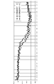
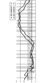
- FIG. 6 shows a diagram in which the first time series data and the second time series data are plotted on a graph.
- the horizontal axis is time, and the vertical axis is system frequency.
- the time shift calculation unit 102 calculates the similarity between two waveforms while shifting (moving) one waveform on the time axis.
- the shifting time is a value obtained by multiplying the sampling period of the first time series data and the second time series data by an integer. Then, the time shift calculation unit 102 calculates the shifted time t when the similarity is equal to or higher than a predetermined level as the time shift between the first clock and the second clock.
- the time lag calculation unit 102 may calculate the correlation coefficient of the first time series data and the second time series data as the similarity. In this case, the time shift calculation unit 102 calculates the shifted time t when the correlation coefficient is equal to or greater than a predetermined value as the time shift between the first clock and the second clock.
- the time-series data of the difference obtained by subtracting the other time-series data from one time-series data (the data obtained by arranging the difference obtained by subtracting the other value from one value in time series for each corresponding timing)
- the similarity may be calculated.
- the time lag calculation unit 102 calculates the shifted time t when a statistical value (eg, maximum value, average value) of a plurality of values included in the time series data of the difference is equal to or less than a predetermined value, You may calculate as a time gap between the 1st timepiece and the 2nd timepiece.
- the time shift calculation unit 102 may calculate the similarity corresponding to each while gradually increasing or decreasing the shift time tn and compare the similarity with a predetermined value. In this case, the number of times of similarity calculation and comparison tends to increase.
- the time lag calculation unit 102 may employ the following algorithm.
- the time lag calculation unit 102 calculates the degree of similarity corresponding to each representative member (eg, t3 and t8) of each group. If any one of the calculated similarities is equal to or greater than a predetermined value, the time shift calculation unit 102 sets the shifted time as the time shift.
- the time lag calculation unit 102 identifies the group with the higher similarity. Then, the degree of similarity is calculated for each member belonging to the specified group and compared with a predetermined value. The degree of similarity of each member of the specified group may be calculated, or the members of the specified group may be grouped in the same manner as described above and the same processing may be performed. According to this method, the number of similarity calculations and comparisons can be reduced.
- first device 10 and the second device 20 may be one-to-one or may be one-to-multiple. This assumption is the same in all the following embodiments.
- the first acquisition unit 101 associates time information at the time of measurement with measurement values of predetermined items of the power system based on the first timepiece used in the first device 10. Based on the time-series data and the plurality of second clocks used in each of the plurality of second devices 20, a plurality of second times in which time information at the time of measurement is associated with measured values of predetermined items of the power system. And time-series data. Then, the time lag calculation unit 102 calculates a time lag between the first clock and each of the plurality of second clocks based on the first time series data and each of the plurality of second time series data. calculate.
- the first device 10 may be provided with a GPS receiver, and may have a function of correcting the time of the first clock based on the GPS signal.
- the time difference between the one or more second timepieces can be accurately calculated. This assumption is the same in all the following embodiments.
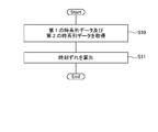
- the first acquisition unit 101 is based on a first clock used in the first device 10, and first time-series data in which time information at the time of measurement is associated with measurement values of predetermined items of the power system. And based on the 2nd timepiece used with the 2nd apparatus 20, the 2nd time series data which matched time information at the time of measurement with the measured value of the predetermined item of an electric power system is acquired (S10). .
- the time lag calculation unit 102 calculates the time lag between the first clock and the second clock based on the first time series data and the second time series data.
- a new technique for calculating the time lag between devices is realized.
- time synchronization between the devices is realized.
- a new time synchronization technique is realized.
- each device it is not necessary for each device to include an expensive device such as a GPS receiver. For this reason, the time synchronization realization method of this embodiment is excellent in cost.
- the time lag can be calculated based on the similarity between the waveform of the first time series data and the waveform of the second time series data.
- the measured value of the predetermined item of the power system may be the same value continuously. For this reason, when the similarity between the first time-series data and the second time-series data is calculated using only measured values at a certain time point, and a time lag is calculated, there is a possibility of calculating an incorrect time lag.
- the time lag calculation accuracy can be increased.
- a third device that is physically and / or logically separated from the first device 10 and the second device 20 may include the control device 100.
- the third device receives the first time-series data and the second time-series data from the first device 10 and the second device 20, and based on them, the first timepiece and the second timepiece The time difference between them is calculated.
- the control device 100 has a function of correcting the first time series data and the second time series data. For example, when the sampling period of the first time-series data and the second time-series data is larger than the minimum value of the time shift to be detected, a desired time shift cannot be detected.
- the control device 100 corrects the sampling period by interpolating the data into the first time series data and the second time series data so that a desired time lag can be detected. This will be described below.
- FIG. 8 shows an example of a functional block diagram of the control device 100 of the present embodiment.
- the control device 100 includes a first acquisition unit 101, a time shift calculation unit 102, and a correction unit 103.
- the configurations of the first acquisition unit 101 and the time shift calculation unit 102 are the same as those in the first embodiment.
- the correction unit 103 interpolates data into the first time series data and the second time series data.
- the first acquisition unit 101 inputs the first time series data and the second time series data to the correction unit 103.
- the correction unit 103 determines whether interpolation is necessary based on a reference value of a sampling period that is held in advance.
- the correction unit 103 determines that the interpolation for the first time-series data and the second time-series data is unnecessary when the “sampling period is equal to or less than the reference value”. Then, the correction unit 103 inputs the first time series data and the second time series data to the time shift calculation unit 102 as they are.
- the correction unit 103 determines that interpolation for the first time series data and the second time series data is necessary. Then, the correction unit 103 performs an interpolation process on the first time-series data and the second time-series data, and then converts the first time-series data and the second time-series data after the interpolation process to a time Input to the deviation calculation unit 102.
- the correction unit 103 can employ any technique to interpolate data. For example, spline interpolation is exemplified. For example, the correcting unit 103 may estimate the data value between the preceding and subsequent data values and interpolate the estimated value.
- the time lag calculation unit 102 calculates the time lag between the first clock and the second clock based on the data input from the correction unit 103.
- the same operational effects as those of the first embodiment can be realized. Further, according to the present embodiment, by interpolating data into the first time-series data and the second time-series data, it becomes possible to increase the resolution of the detectable time lag and calculate the desired time lag. .
- the control system of the present embodiment further has a function of correcting the second clock based on the calculated time lag and synchronizing the first clock and the second clock. This will be described below. In the present embodiment, it is assumed that the first device 10 shown in FIG.
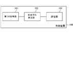
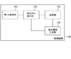
- FIG. 9 shows an example of a functional block diagram of the control device 100 of the present embodiment.
- the control device 100 includes a first acquisition unit 101, a time shift calculation unit 102, and a transmission unit 104.
- the control device 100 may further include a correction unit 103.
- the configurations of the first acquisition unit 101, the time shift calculation unit 102, and the correction unit 103 are the same as those in the first and second embodiments.
- the transmission unit 104 transmits to the second device 20 a correction instruction for correcting the second clock based on the calculated time difference.
- the correction instruction includes the contents of the time lag (the progress time or the delay time).
- the second device 20 that has received the correction instruction corrects the second clock according to the correction instruction, and eliminates the time lag with respect to the first clock.
- the same operational effects as those of the first and second embodiments can be realized. Further, according to the present embodiment, the first clock and the second clock can be synchronized by correcting the second clock.
- the control system of the present embodiment further has a function of correcting the second clock based on the calculated time lag and synchronizing the first clock and the second clock. This will be described below. In the present embodiment, it is assumed that the second device 20 shown in FIG.
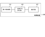
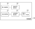
- FIG. 10 shows an example of a functional block diagram of the control device 100 of the present embodiment.
- the control device 100 includes a first acquisition unit 101, a time lag calculation unit 102, and a correction unit 107.
- the control device 100 may further include a correction unit 103.
- the configurations of the first acquisition unit 101, the time shift calculation unit 102, and the correction unit 103 are the same as those in the first to third embodiments.
- the correction unit 107 corrects the second clock based on the calculated time lag, and eliminates the time lag with the first clock.
- the same operational effects as those of the first and second embodiments can be realized. Further, according to the present embodiment, the first clock and the second clock can be synchronized by correcting the second clock.
- the control system according to the present embodiment further has a function of generating estimation information for calculating the time shift from the elapsed time based on the past performance indicating the elapsed time and the time shift generated during that time. This will be described below.
- the first device 10 shown in FIG. it is assumed that the first device 10 shown in FIG. That is, the first device 10 generates estimation information. Then, the first device 10 calculates a time lag based on the estimated information and the elapsed time.
- FIG. 11 shows an example of a functional block diagram of the control device 100 of the present embodiment.
- the control device 100 includes a first acquisition unit 101, a time shift calculation unit 102, a transmission unit 104, and an estimated information generation unit 105.
- the control device 100 may further include a correction unit 103.
- the configurations of the first acquisition unit 101, the time shift calculation unit 102, the correction unit 103, and the transmission unit 104 are the same as those in the first to fourth embodiments.
- the estimated information generation unit 105 generates estimated information for calculating the time lag from the elapsed time based on the elapsed time and the past results indicating the time lag generated during the elapsed time.
- the time lag calculation unit 102 repeatedly calculates the time lag between the first clock and the second clock at a predetermined cycle (a cycle of several tens of minutes to several hours). Then, the transmission unit 104 transmits a correction instruction based on the calculated time lag to the second device 20 each time.
- the elapsed time is an elapsed time from the nth process to the (n + 1) th process.
- the time lag occurring during the elapsed time is the time lag calculated in the (n + 1) th process.
- the timing at which the correction instruction is transmitted to the second device 20 in the n-th process may be set as the starting point of the elapsed time.
- the first device 10 may receive a completion notification indicating that the correction of the second clock has been completed from the second device 20.
- the 1st apparatus 10 is good also considering the said reception timing as the starting point of elapsed time.
- the timing at which the time lag is calculated in the (n + 1) th process may be the end point of the elapsed time.
- Such past results are stored in the control device 100 or in an external device configured to be able to communicate with the control device 100.
- the relationship between the first device 10 and the second device 20 is one-to-multiple, past results are accumulated in association with each of the plurality of second devices 20.
- the estimation information generation unit 105 generates estimation information (eg, estimation formula) for calculating a time lag from the elapsed time based on such past results.
- estimation information eg, estimation formula
- the generation method of the estimation information is a design matter, and for example, a method such as regression analysis can be adopted.
- the time lag calculating unit 102 can calculate the time lag between the first clock and the second clock based on the estimated information and the elapsed time after the estimated information is generated.
- the same operational effects as those of the first to fourth embodiments can be realized. Further, according to the present embodiment, it is possible to calculate the time difference between the first clock and the second clock based on the elapsed time and the estimated information. After the estimation information is generated, the calculation method based on the first time series data and the second time series data is replaced with a calculation method based on the elapsed time and the estimation information, so that the calculation burden on the computer can be reduced.
- the relationship between the first device 10 and the second device 20 is one-to-multiple.
- the control system of the present embodiment groups a plurality of second clocks used in each of the plurality of second devices 20 based on the past results described in the fifth embodiment. And it has further the function which produces
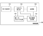
- FIG. 12 shows an example of a functional block diagram of the control device 100 of the present embodiment.
- the control device 100 includes a first acquisition unit 101, a time lag calculation unit 102, a transmission unit 104, an estimated information generation unit 105, and a first grouping unit 106.
- the control device 100 may further include a correction unit 103.
- the configurations of the first acquisition unit 101, the time shift calculation unit 102, the correction unit 103, and the transmission unit 104 are the same as those in the first to fifth embodiments.
- the first grouping unit 106 groups a plurality of second clocks used in each of the plurality of second devices 20 based on past results.
- the past performance is data indicating the elapsed time and the time lag generated between the elapsed times.
- the first grouping unit 106 creates a group of second clocks having similar time shift trends.
- the grouping method is a design matter.
- the time lag at the elapsed time m may be divided into a group having a predetermined value or more and a group having a predetermined value or less.
- the number of groups is not limited to two and may be more than that.
- the estimation information generation unit 105 generates estimation information common to each group for each group. That is, the estimated information generation unit 105 does not generate estimated information for each second clock, but generates estimated information for each group.
- the estimation information generation unit 105 estimates, for each group, estimation information that calculates a time lag from the elapsed time based on all or part of past results of a plurality of members (second clocks) of each group (example: estimation) Expression).
- the generation method of the estimation information is a design matter, and for example, a method such as regression analysis can be adopted.
- the time lag calculating unit 102 can calculate the time lag between the first clock and the second clock based on the estimated information and the elapsed time after the estimated information is generated.
- the time lag calculation unit 102 calculates the time lag of each of the second clocks based on the estimation information generated corresponding to the group to which each of the second clocks belongs.
- the same operational effects as those of the first to fifth embodiments can be realized.
- the control system of the present embodiment further has a function of generating estimation information for calculating a time shift from the elapsed time based on past results indicating the elapsed time and the time shift therebetween. This will be described below.
- the second device 20 shown in FIG. it is assumed that the second device 20 shown in FIG. That is, the second device 20 generates estimation information. Then, the second device 20 calculates a time lag based on the estimated information and the elapsed time.
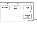
- FIG. 13 shows an example of a functional block diagram of the control device 100 of the present embodiment.
- the control device 100 includes a first acquisition unit 101, a time lag calculation unit 102, an estimated information generation unit 105, and a correction unit 107.
- the control device 100 may further include a correction unit 103.
- the configurations of the first acquisition unit 101, the time shift calculation unit 102, the correction unit 103, and the correction unit 107 are the same as those in the first to sixth embodiments.
- the estimated information generation unit 105 generates estimated information for calculating the time lag from the elapsed time based on the elapsed time and the past results indicating the time lag generated during the elapsed time.
- the time lag calculation unit 102 repeatedly calculates the time lag between the first clock and the second clock at a predetermined cycle (a cycle of several tens of minutes to several hours). Then, the correction unit 107 corrects the second timepiece based on the calculated time difference each time.
- the elapsed time is an elapsed time from the nth process to the (n + 1) th process.
- the time lag occurring during the elapsed time is the time lag calculated in the (n + 1) th process.
- the timing at which the second clock is corrected in the n-th process may be set as the starting point of the elapsed time.
- the timing at which the time lag is calculated in the (n + 1) th process may be the end point of the elapsed time.
- Such past results are stored in the control device 100 or in an external device configured to be able to communicate with the control device 100.
- each control device 100 included in each second device 20 or an external device configured to be able to communicate with each control device 100 Each past performance is accumulated in the inside.
- the estimation information generation unit 105 generates estimation information (eg, estimation formula) for calculating a time lag from the elapsed time based on such past results.
- estimation information eg, estimation formula
- the generation method of the estimation information is a design matter, and for example, a method such as regression analysis can be adopted.
- the time lag calculating unit 102 can calculate the time lag between the first clock and the second clock based on the estimated information and the elapsed time after the estimated information is generated.
- the same operational effects as those of the first to fourth embodiments can be realized. Further, according to the present embodiment, it is possible to calculate the time difference between the first clock and the second clock based on the elapsed time and the estimated information. After the estimation information is generated, the calculation method based on the first time series data and the second time series data is replaced with a calculation method based on the elapsed time and the estimation information, so that the calculation burden on the computer can be reduced.
- the first device 10 shown in FIG. 2 transmits a control signal to the second device 20.
- the second device 20 operates based on the control signal.
- the control device 100 further has a function of calculating a response time from the transmission of the control signal by the first device 10 until the operation according to the control signal by the second device 20 is performed. This will be described below.
- FIG. 14 shows an example of a functional block diagram of the control device 100 of the present embodiment.
- the control device 100 includes a first acquisition unit 101, a time lag calculation unit 102, a second acquisition unit 201, and a response time calculation unit 202.
- the control apparatus 100 further includes one or more of a correction unit 103, a transmission unit 104, an estimation information generation unit 105, a first grouping unit 106, and a correction unit 107. Also good.
- the configurations of the first acquisition unit 101, time shift calculation unit 102, correction unit 103, transmission unit 104, estimation information generation unit 105, first grouping unit 106, and correction unit 107 are the first to seventh embodiments. It is the same.
- the second acquisition unit 201 acquires the third time series data and the fourth time series data.
- the third time series data indicates the content of the control signal transmitted from the first device 10 to the second device 20 and the transmission time from the first device 10 attached based on the first clock.
- the fourth time-series data indicates the operation content of the second device 20 and the operation time assigned based on the second clock.
- the first device 10 is a central control device that transmits a storage battery control signal (control signal) and the second device 20 is a terminal-side control device that controls the storage battery based on the storage battery control signal (control signal), the storage battery
- the content of the control signal (control signal) is, for example, a command value for the output power [W] or the charging power [W] of the storage battery.
- the operation content of the second device 20 is a measured value (response value) of the output power [W] or the charging power [W] of the storage battery operated under the control of the second device 20.
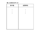
- FIGS. 15 and 16 schematically show examples of such third time-series data and fourth time-series data.
- the content of the storage battery control signal may be a value for calculating a command value for the output power [W] or the charging power [W] of the storage battery. For example, information for specifying the burden ratio is given to each of the plurality of second devices 20 in advance. Then, as the storage battery control signal (control signal), the value of the output power [W] or the charging power [W] of the entire plurality of storage batteries is transmitted to each second device 20.
- the contents transmitted to the plurality of second devices 20 are the same contents, they may be transmitted simultaneously by broadcast or the like.
- Each second device 20 calculates its own share of the output power [W] or charging power [W] of the plurality of storage batteries as a command value.
- control signal The premise regarding the contents of the storage battery control signal (control signal) is the same in all of the following embodiments. Even in such a case, it is possible to realize the same effect as the case where the content of the storage battery control signal (control signal) is a command value.
- the first device 10 generates third time series data
- the second device 20 generates fourth time series data.
- the control device 100 When the first device 10 shown in FIG. 2 includes the control device 100, the control device 100 generates third time series data and receives the fourth time series data from the second device 20.
- the second device 20 may transmit a response value measured at a cycle of several seconds to the first device 10 (the control device 100) at a cycle of several seconds.
- the second device 20 accumulates response values measured, for example, in a cycle of several seconds, and collects the accumulated response values, for example, the first device 10 (control device 100) in a cycle of several tens of minutes to several hours, for example. May be sent to. This assumption is the same in all the following embodiments.
- the control device 100 When the second device 20 includes the control device 100, the control device 100 generates fourth time-series data and receives the third time-series data from the first device 10.
- the response time calculation unit 202 calculates the response time from the transmission time of the control signal to the operation time when the operation corresponding to the control signal is performed based on the third time series data and the fourth time series data. .
- the response time calculation unit 202 calculates a response time based on the similarity between the waveform of the third time series data and the waveform of the fourth time series data.
- the response time calculation unit 202 is based on a waveform based on data for a predetermined time in the third time-series data and a waveform similarity based on the data for the predetermined time in the fourth time-series data.
- the time lag can be calculated.
- the predetermined time is a design matter that can be determined within a range in which a rough tendency of the waveform (a trend component excluding noise) can be understood.
- FIG. 17 shows a diagram in which the third time-series data and the fourth time-series data are plotted on a graph.
- the horizontal axis is time
- the vertical axis is a value obtained by standardizing command values and response values under predetermined conditions.
- the response time calculation unit 202 calculates the similarity between two waveforms while shifting one waveform on the time axis (moving).
- the shifting time is a value obtained by multiplying the sampling period of the third time series data and the fourth time series data by an integer. Then, the response time calculation unit 202 calculates the shifted time t ′ when the similarity is equal to or higher than a predetermined level as the response time.
- the response time calculation unit 202 may calculate the correlation coefficient of the third time series data and the fourth time series data as the similarity. In this case, the response time calculation unit 202 calculates the shifted time t ′ when the correlation coefficient is equal to or greater than a predetermined value as the response time.
- the time-series data of the difference obtained by subtracting the other time-series data from one time-series data (the data obtained by arranging the difference obtained by subtracting the other value from one value in time series for each corresponding timing)
- the similarity may be calculated.
- the response time calculation unit 202 calculates a shifted time t ′ when a statistical value (eg, maximum value, average value) of a plurality of values included in the time series data of the difference is equal to or less than a predetermined value.
- the response time may be calculated.
- the second acquisition unit 201 uses third time-series data based on the first clock used in the first device 10. And a plurality of fourth time series data based on each of the plurality of second clocks used in each of the plurality of second devices 20. Then, the response time calculation unit 202 calculates a response time corresponding to each of the plurality of second devices 20 based on the third time series data and each of the plurality of fourth time series data.
- the same operational effects as those of the first to seventh embodiments can be realized. Further, according to the present embodiment, the response time from the transmission time at which the control signal is transmitted from the first device 10 to the operation time at which the operation by the second device 20 corresponding to the control signal is performed is calculated. be able to. With the method described in the first to seventh embodiments, time synchronization between the first clock used in the first device 10 and the second clock used in the second device 20 is performed. Thus, the response time can be calculated with high accuracy.
- the response time can be calculated based on the similarity between the waveform of the third time series data and the waveform of the fourth time series data.
- the command value and the response value may be the same value in succession. For this reason, when the similarity between the third time-series data and the fourth time-series data is calculated using only the command value and the response value at a certain point in time and the response time is calculated, there is a possibility of calculating an incorrect response time. is there. In the case of this embodiment in which the response time can be calculated based on the similarity between the waveform of the third time series data and the waveform of the fourth time series data, the calculation accuracy of the response time can be increased.
- the first device 10 transmits a control signal to the second device 20.
- the second device 20 operates based on the control signal.
- the control device 100 that calculates the time difference between the first timepiece and the second timepiece and the control device 200 that is physically and / or logically separated responds to the control signal from the transmission time of the control signal. The response time until the operation time at which the operation is performed is calculated.
- control device 100 that calculates the time difference between the first timepiece and the second timepiece” and “the operation in which the operation according to the control signal is performed from the transmission time of the control signal”
- the control device 200 for calculating the response time up to the time is physically and / or logically separated.
- FIG. 3 shows an example of a functional block diagram of the control device 100.
- the control device 100 includes a first acquisition unit 101 and a time shift calculation unit 102.
- the control device 100 may further include one or more of a correction unit 103, a transmission unit 104, an estimation information generation unit 105, a first grouping unit 106, and a correction unit 107.
- the configurations of the first acquisition unit 101, the time shift calculation unit 102, the correction unit 103, the transmission unit 104, the estimation information generation unit 105, the first grouping unit 106, and the correction unit 107 are the first to eighth embodiments. It is the same.
- FIG. 18 shows an example of a functional block diagram of the control device 200.
- the control device 200 includes a second acquisition unit 201 and a response time calculation unit 202.
- the configurations of the second acquisition unit 201 and the response time calculation unit 202 are the same as those in the eighth embodiment.
- one of the first device 10 and the second device 20 shown in FIG. 2 has the control device 100, and the other has the control device 200.
- the first device 10 may include the control device 100 and the second device 20 may include the control device 200.
- the second device 20 may include the control device 100, and the second device 20 may include the control device 100.
- the same functions and effects as those of the first to eighth embodiments can be realized. Further, the calculation of the time lag and the calculation of the response time can be divided into the first device 10 and the second device 20. For this reason, the inconvenience that the processing load is concentrated on one side can be avoided.
- the control device 100 of the present embodiment is based on the configuration of the eighth embodiment, and further has a function of grouping a plurality of second devices 20 based on the calculated response time. This will be described below.
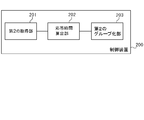
- FIG. 19 shows an example of a functional block diagram of the control device 100 of the present embodiment.
- the control device 100 includes a first acquisition unit 101, a time lag calculation unit 102, a second acquisition unit 201, a response time calculation unit 202, and a second grouping unit 203.
- the control apparatus 100 may further include one or more of a correction unit 103, a transmission unit 104, an estimation information generation unit 105, a first grouping unit 106, and a correction unit 107.
- the configuration 202 is the same as in the first to ninth embodiments.
- the second grouping unit 203 groups a plurality of second devices 20 based on the response time.
- the second grouping unit 203 generates a group of those having similar response times.
- the grouping method is a design matter.
- the response time may be divided into a group having a predetermined value or more and a group having a response time less than the predetermined value.
- the number of groups is not limited to two and may be more than that.
- the 1st apparatus 10 may select the 2nd apparatus 20 which belongs to a group whose response time is contained in a predetermined range among a plurality of groups as a candidate for a control object.
- This technique is disclosed in Patent Document 1, for example.
- a plurality of storage batteries are grouped based on communication characteristics (communication delay time, packet error rate in communication path, bit error rate in communication path, etc.) between the storage battery and the battery control system.
- a technique for selecting a storage battery included in a group having communication characteristics within a predetermined range as a candidate for an adjustment battery is disclosed.
- “communication characteristics” in the technique disclosed in Patent Document 1 can be replaced with “response time” of the present application.
- the second devices 20 can be grouped based on the response time based on the similar characteristics (response time). For example, the processing load on the first device 10 can be reduced by controlling the plurality of second devices 20 in units of groups rather than individually.
- the control device 100 of the present embodiment is based on the configuration of the ninth embodiment, and further has a function of grouping a plurality of second devices 20 based on response time. This will be described below.
- FIG. 20 shows an example of a functional block diagram of the control device 100 of the present embodiment.
- the control device 100 includes a second acquisition unit 201, a response time calculation unit 202, and a second grouping unit 203.
- the configurations of the second acquisition unit 201, the response time calculation unit 202, and the second grouping unit 203 are the same as those in the first to tenth embodiments.
- the control device 100 of the tenth embodiment performs an operation according to the control signal from the “function for calculating the time difference between the first timepiece and the second timepiece” and “the transmission time of the control signal. It has a function of calculating a response time until the operation time and a function of grouping a plurality of second devices 20 based on the response time (see FIG. 19).
- the control device 100 according to the present embodiment does not have the “function of calculating the time lag between the first clock and the second clock”, that is, the first acquisition unit 101 and the time lag calculation unit 102 are included. It differs from the control apparatus 100 of 10th Embodiment by not having (refer FIG. 20).
- the second grouping unit 203 groups a plurality of second devices 20 based on the response time.
- the second grouping unit 203 generates a group of those having similar response times.
- the grouping method is a design matter.
- the response time may be divided into a group having a predetermined value or more and a group having a response time less than the predetermined value.
- the number of groups is not limited to two and may be more than that.
- the 1st apparatus 10 may select the 2nd apparatus 20 which belongs to a group whose response time is contained in a predetermined range among a plurality of groups as a candidate for a control object.
- This technique is disclosed in Patent Document 1, for example.
- a plurality of storage batteries are grouped based on communication characteristics (communication delay time, packet error rate in communication path, bit error rate in communication path, etc.) between the storage battery and the battery control system.
- a technique for selecting a storage battery included in a group having communication characteristics within a predetermined range as a candidate for an adjustment battery is disclosed.
- “communication characteristics” in the technique disclosed in Patent Document 1 can be replaced with “response time” of the present application.
- the second devices 20 can be grouped based on the response time based on the similar characteristics (response time). For example, the processing load on the first device 10 can be reduced by controlling the plurality of second devices 20 in units of groups rather than individually.
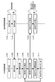
- FIG. 21 shows an overall view of the control system of the present embodiment.
- the control system includes a central control device 11 that transmits a storage battery control signal (eg, LFC (Load Frequency Control) signal, GF (Governor Free) signal), and a plurality of terminal-side control devices that control the storage battery 50 based on the storage battery control signal.
- a storage battery control signal eg, LFC (Load Frequency Control) signal, GF (Governor Free) signal
- the central control device 11 corresponds to the first device 10
- the terminal-side control device 21 corresponds to the second device 20.
- the configurations of the first device 10 and the second device 20 are the same as those in the first to eleventh embodiments.
- the central control device 11 and the plurality of terminal-side control devices 21 are connected via the communication line 30 and can transmit and receive information to and from each other.
- the central control device 11 transmits a storage battery control signal to each of the plurality of terminal-side control devices 21.
- the storage battery control signal is a signal for specifying a command value of output power [W] or charging power [W] of the storage battery, for example.
- the storage battery control signal may indicate the command value itself, or may be a value for calculating the command value. In the latter case, each terminal-side control device 21 calculates a command value based on the storage battery control signal.
- the storage battery control signal may include information (eg, time) indicating the timing of performing a response with the command value.
- Each of the plurality of terminal-side control devices 21 is connected to the corresponding storage battery 50 through a communication line, and inputs a control signal to the corresponding storage battery 50.
- the terminal-side control device 21 specifies a command value based on the storage battery control signal, and causes the storage battery 50 to respond with the specified command value.
- the terminal-side control device 21 sets the storage battery 50 so as to continue the response with the command value specified based on the previous storage battery control signal until the next storage battery control signal is received. You may control.
- the storage battery 50 is connected to the power line 40.
- the storage battery 50 supplies power to the power line 40 with a predetermined output power [W] (output) or receives power from the power line 40 and charges with a predetermined charging power [W] according to the control of the terminal-side control device 21. To do.
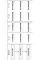
- FIG. 22 shows a basic flow of the control system of this embodiment. As illustrated, it includes “calculation of time lag”, “correction of time lag”, and “calculation of response time”.
- time lag between the first clock used for the central control device 11 and the plurality of second clocks used for each of the plurality of terminal-side control devices 21 is calculated.
- the central control device 11 includes a GPS receiver and can have a function of correcting the time of the first clock based on the GPS signal. In addition, it can also be set as the embodiment in which the central controller 11 does not include a GPS receiver.
- each of the plurality of second clocks used in each of the plurality of terminal-side control devices 21 is corrected to eliminate the time lag between the first clock and the second clock.
- response time is calculated corresponding to each of the plurality of terminal-side control devices 21.
- the response time is the time from the transmission time of the storage battery control signal to the operation time when the operation according to the storage battery control signal is performed.
- central control device 11 or the terminal-side control device 21 performs each of the above three steps, it can be divided into four cases.
- the central control device 11 performs “calculation of time lag”, each terminal side control device 21 performs “correction of time lag”, and each terminal side control device 21 performs “calculation of response time”.
- each terminal-side control device 21 performs “calculation of time lag”, each terminal-side control device 21 performs “correction of time lag”, and the central control device 11 performs “calculation of response time”.
- each terminal-side control device 21 performs “calculation of time lag”, each terminal-side control device 21 performs “correction of time lag”, and each terminal-side control device 21 performs “calculation of response time”. Do.
- FIG. 23 shows an example of a processing flow in which the central controller 11 executes “calculation of time lag”.
- time series data of measured values of predetermined items of the power system is measured.
- the time series data is associated with time information at the time of measurement of each measurement value based on the first clock used in the central controller 11 (first time series data).
- the central controller 11 includes a GPS receiver, and corrects the first clock (time synchronization) based on the GPS signal at a predetermined timing.
- time series data of measured values of predetermined items of the power system is measured.
- the time series data is associated with time information at the time of measurement of each measurement value based on the second clock used in each of the plurality of terminal-side control devices 21 (second time series data).
- the plurality of terminal-side control devices 21 transmit each second time-series data to the central control device 11.
- the central control device 11 receives second time-series data corresponding to each of the plurality of terminal-side control devices 21.
- the central controller 11 accumulates the first time series data and the second time series data.
- the processing from S101 to S105 is repeatedly executed at a cycle of several seconds.
- the processing of S106 to S111 is repeatedly executed at a cycle of several tens of minutes to several hours.
- the central controller 11 determines each of the first timepiece and the plurality of second timepieces based on the first time series data accumulated so far and each of the plurality of second time series data. The time difference with is calculated.
- the central control device 11 transmits a correction instruction including the calculated time lag to each of the plurality of terminal-side control devices 21.
- each terminal-side control device 21 receives a correction instruction including the calculated time lag.
- each terminal-side control device 21 corrects the second clock according to the correction instruction, and eliminates the time lag with respect to the first clock.
- the central control apparatus 11 accumulates the transmission timing (transmission date and time) of the correction instruction and the time lag for each terminal-side control apparatus 21.
- the central controller 11 In S111, the central controller 11 generates estimated information for calculating a time lag from the elapsed time based on the information accumulated in S110.
- the terminal-side control device 21 measures the signal at a cycle of several seconds (S102), and instead of the process of transmitting the signal to the central control device 11 at a cycle of several seconds (S103), measures the signal at a cycle of several seconds.
- the signals may be accumulated, and the accumulated signals may be collectively transmitted to the central controller 11 with a period of several tens of minutes to several hours. Other processing can be the same as described above.
- FIG. 24 shows an example of a processing flow in which each terminal-side control device 21 executes “calculation of time lag”.
- time series data of measured values of predetermined items of the power system is measured.
- the time series data is associated with time information at the time of measurement of each measurement value based on the first clock used in the central controller 11 (first time series data).
- the central controller 11 includes a GPS receiver, and corrects the first clock (time synchronization) based on the GPS signal at a predetermined timing.
- time series data of measured values of predetermined items of the power system is measured.
- the time series data is associated with time information at the time of measurement of each measurement value based on the second clock used in each of the plurality of terminal-side control devices 21 (second time series data).
- the central control device 11 transmits the first time-series data to each of the plurality of terminal-side control devices 21.
- each terminal-side control device 21 receives the first time-series data.
- each terminal-side control device 21 accumulates the first time-series data and the second time-series data.
- the processing from S201 to S205 is repeatedly executed at a cycle of several seconds.
- the processing from S206 to S209 is repeatedly executed at a cycle of several tens of minutes to several hours.
- each terminal-side control device 21 shifts the time between the first clock and the second clock based on the first time-series data and the second time-series data accumulated so far. Is calculated.
- each terminal-side control device 21 corrects the second clock based on the calculated time lag and eliminates the time lag with respect to the first clock.
- each terminal-side control device 21 stores the correction timing (correction date and time) and the time lag.
- each terminal-side control device 21 generates estimated information for calculating a time lag from the elapsed time based on the information accumulated in S208.
- a time lag is calculated based on the estimated information generated in S209 and the elapsed time. Thereafter, the same processing is repeated.
- the central control device 11 measures the signal at a cycle of several seconds (S201), and instead of the process of transmitting the signal to the terminal-side control device 21 at a cycle of several seconds (S203), measures the signal at a cycle of several seconds.
- the signals may be accumulated, and the accumulated signals may be collectively transmitted to the terminal-side control device 21 with a period of several tens of minutes to several hours. Other processing can be the same as described above.
- FIG. 25 shows an example of a processing flow in which the central controller 11 executes “calculation of response time”.
- the central controller 11 calculates a command value.
- the central control device 11 transmits a command value to each terminal-side control device 21.
- the central controller 11 stores the command value and the transmission time in association with each other (third time-series data).
- each terminal-side control device 21 receives the command value.
- each terminal-side control device 21 accumulates the command value.
- each terminal-side control device 21 transmits a control signal to the storage battery 50 and makes it respond with a command value.
- each terminal-side control device 21 measures and accumulates the response value (output power or charging power) of each storage battery 50.
- the response value is stored in association with the time of measurement (fourth time series data).
- S306 is executed after S305, but S306 may be a flow independent of S303 to S305. That is, in S306, regardless of the processing in S303 to S305, the output power or the charging power of each storage battery 50 may be repeatedly measured and stored in association with the time of measurement.
- the processing from S301 to S306 is repeatedly executed at a cycle of several seconds.
- the processing from S307 to S313 is repeatedly executed at a cycle of several tens of minutes to several hours.
- each terminal-side control device 21 transmits the fourth time-series data in which the response value is associated with the measurement time to the central control device 11.
- the central control device 11 receives and accumulates the fourth time-series data from each terminal-side control device 21.
- the central control device 11 determines the response time corresponding to each terminal-side control device 21 based on the third time-series data and each of the fourth time-series data received from each terminal-side control device 21. Calculate an estimate.
- the central controller 11 accumulates the estimated response time calculated for each terminal-side controller 21.
- the central control device 11 transmits an estimated value of the response time calculated corresponding to each terminal-side control device 21 to each terminal-side control device 21.
- each terminal-side control device 21 receives an estimated value of response time.
- each terminal-side control device 21 accumulates the estimated response time.
- the terminal-side control device 21 measures the response value at a cycle of several seconds (S306), and instead of the process of transmitting the response value to the central control device 11 at a cycle of several seconds (S307), measures the response value at a cycle of several seconds,
- the measured response values may be accumulated, and the response values accumulated in a period of several tens of minutes to several hours may be collectively transmitted to the central controller 11.
- Other processing can be the same as described above.
- the terminal-side control device 21 when receiving the command value (S303), the terminal-side control device 21 causes the storage battery 50 to execute a response with the command value without delay in response to the reception (S305).
- a response time may be associated with the command value.
- the terminal side control apparatus 21 may make the storage battery 50 perform the response by a command value, if it detects that it became the response time or the time (time or time) before the response time.
- the terminal-side control device 21 keeps the storage battery 50 at the previous command value until it detects that the response time of the next command value or a time (time or time) a predetermined time before the response time is reached. The response may be continued.
- the central control device 11 calculates a command value corresponding to each terminal-side control device 21 (S301), and executes the following process instead of the process of transmitting the command value (S302). Also good. That is, as described in the eighth embodiment, the central control device 11 may calculate a value for calculating the command value instead of the command value and transmit the value to the terminal-side control device 21. And each terminal side control apparatus 21 may calculate the command value corresponding to self.
- a burden ratio is given to each of the plurality of terminal-side control devices 21 in advance.
- the central control device 11 calculates the value of the output power [W] or the charging power [W] across the plurality of storage batteries 50 in S301, and transmits the value to each terminal-side control device 21 in S302.
- Each terminal-side control device 21 receives the value transmitted in S302 (S303). Then, each terminal-side control device 21 calculates a share ratio given in advance among the values received in S303 as a command value corresponding to itself.
- S311 to S313 may be omitted from the flow.
- a consumer side user who manages the terminal side control apparatus 21
- FIG. 26 shows an example of a processing flow in which each terminal-side control device 21 executes “response time calculation”.
- the central controller 11 calculates a command value.
- the central control device 11 transmits a command value to each terminal-side control device 21.
- the information transmitted here includes the transmission time at which the central controller 11 transmits the command value.
- each terminal-side control device 21 receives the command value.
- each terminal-side control device 21 accumulates the command value and the transmission time (third time-series data).
- each terminal-side control device 21 transmits a control signal to the storage battery 50 and makes it respond with a command value.
- each terminal-side control device 21 measures and stores the response value (output power or charging power) of each storage battery 50.
- the response value is stored in association with the time of measurement (fourth time series data).
- S406 is executed after S405, but S406 may be a flow independent from S403 to S405. That is, in S406, regardless of the processing in S403 to S405, the output power or the charging power of each storage battery 50 may be repeatedly measured and stored in association with the time of measurement.
- the processing from S401 to S406 is repeatedly executed at a cycle of several seconds.
- the processing from S407 to S410 is repeatedly executed at a cycle of several tens of minutes to several hours.
- each terminal-side control device 21 calculates an estimated value of the response time of each terminal-side control device 21 based on the third time-series data and the fourth time-series data.
- each terminal-side control device 21 transmits the calculated estimated response time value to the central control device 11.
- the central controller 11 receives the estimated response time from each terminal-side controller 21.
- the central control device 11 stores the estimated response time in association with each terminal-side control device 21.
- the terminal-side control device 21 when receiving the command value (S403), the terminal-side control device 21 causes the storage battery 50 to execute a response with the command value without delay (S405).
- a response time may be associated with the command value.
- the terminal side control apparatus 21 may make the storage battery 50 perform the response by a command value, if it detects that it became the response time or the time (time or time) before the response time.
- the terminal-side control device 21 keeps the storage battery 50 at the previous command value until it detects that the response time of the next command value or a time (time or time) a predetermined time before the response time is reached. The response may be continued.
- the central control device 11 calculates a command value corresponding to each terminal-side control device 21 (S401), and executes the following process instead of the process of transmitting the command value (S402). Also good. That is, as described in the eighth embodiment, the central control device 11 may calculate a value for calculating the command value instead of the command value and transmit the value to the terminal-side control device 21. And each terminal side control apparatus 21 may calculate the command value corresponding to self.
- a burden ratio is given to each of the plurality of terminal-side control devices 21 in advance.
- the central control device 11 calculates the value of the output power [W] or the charging power [W] for the entire plurality of storage batteries 50 in S401, and transmits the value to each terminal-side control device 21 in S402.
- Each terminal-side control device 21 receives the value transmitted in S402 (S403).
- each terminal-side control device 21 calculates a share ratio given in advance among the values received in S403 as a command value corresponding to itself.
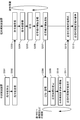
- the control system of the application example has a central system and a terminal system.
- the central system and the terminal system can communicate with each other.
- one terminal side system is shown, but the relationship between the central side system and the terminal side system may be one to plural.
- the central system has a central controller 11, and the terminal system has a terminal controller 21.
- the central system has a central power supply command center system and a cloud server.
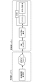
- the terminal side system includes a GW (gateway), a local terminal, and an ESS (Energy Storage System).
- the ESS includes a system controller (syscon), a PCS (Power Conditioning System), and a storage battery.
- the central power supply command center system has a central controller 11.
- the system of the central power supply command station calculates a command value or a value for calculating the command value. Then, the central power supply command station system transmits the calculated command value or a storage battery control signal including a value for calculating the command value to the terminal-side system via the cloud server.
- the storage battery control signal may further include a response time.
- the system of the central power supply command station may grasp the current time based on the first clock and determine the response time based on the current time.
- the central power supply command may determine a response time and a command value at that time or a value for calculating the command value based on the response time. For example, the system of the central power supply command station specifies the maximum value Tmax in the response time T corresponding to each of the plurality of terminal-side control devices 21, and the time when Tmax has elapsed from the current time determined based on the first clock. A later time may be determined as the response time.
- the storage battery of the terminal-side system is connected to the power system, and performs power output (reverse power flow) to the power system and power reception (charging) from the power system.
- the PCS controls power output from the storage battery and charging to the storage battery in accordance with a control signal from the system controller.
- the control signal includes a command value (output power [W] / charging power [W]). For example, when receiving a command value from the system controller, the PCS causes the storage battery to execute a response with the command value without delay.
- System controller controls ESS operation.
- the system controller may include the terminal side control device 21.
- the storage battery control signal transmitted from the central system is input to the system controller via the GW and the local terminal.
- you may input into a system controller from GW not via a local terminal.
- the system controller that acquired the storage battery control signal specifies the command value based on the storage battery control signal. Further, the system controller specifies a response time based on the storage battery control signal. Then, the system controller detects that the response time or the time (time or time) that is a predetermined time before the response time is reached based on the current time determined based on the second clock.
- the predetermined time here may be determined based on, for example, the time required from the transmission of the control signal from the system controller to the response of the storage battery.
- the system controller transmits to the PCS a control signal to respond (output / charge) with the command value.
- the PCS When receiving the command value from the system controller, the PCS causes the storage battery to execute a response with the command value without delay.
- the system controller can recognize the command value of the storage battery control signal from the response time based on the storage battery control signal or the current time based on the second clock, a predetermined time before the response time. Until the system controller and PCS detect that the next response time or the time (time or time) a predetermined time before the next response time is detected, the battery controller continues the response with the previous command value. Also good.
- the storage battery control signal may not include the response time.
- the system controller repeatedly receives the storage battery control signal at a predetermined cycle (eg, a cycle of several seconds).
- a predetermined cycle e.g, a cycle of several seconds.
- the system controller specifies the command value without delay and transmits a control signal for responding with the command value to the PCS.
- the PCS causes the storage battery to execute a response with the command value without delay.
- the local terminal may have the terminal-side control device 21.
- the storage battery control signal transmitted from the central system is input to the local terminal via the GW.
- the local terminal that has acquired the storage battery control signal specifies a command value based on the storage battery control signal.
- the local terminal specifies the response time based on the storage battery control signal.
- the local terminal detects that the response time or the time (time or time) before the response time is reached based on the current time determined based on the second clock.
- the predetermined time here may be determined based on, for example, the time required from the transmission of the control signal from the local terminal to the response of the storage battery.
- the local terminal transmits a control signal to respond (output / charge) with the command value to the system controller.
- the system controller When receiving a command value from the local terminal, the system controller transmits a control signal to respond to the command value to the PCS without delay in response to the command value.
- the PCS When receiving the command value from the system controller, the PCS causes the storage battery to execute a response with the command value without delay.
- the system controller can recognize the command value of the storage battery control signal from the response time based on the storage battery control signal or the current time based on the second clock, a predetermined time before the response time.
- the system controller, the PCS, and the local terminal send a response at the previous command value to the storage battery until it detects that the next response time or a time (time or time) a predetermined time before the next response time is reached. It may be continued.
- the storage battery control signal may not include the response time.
- the local terminal repeatedly receives the storage battery control signal at a predetermined cycle (eg, a cycle of several seconds).
- the local terminal specifies a command value without delay and transmits a control signal for responding with the command value to the system controller.
- the system controller receives a control signal including a command value from the local terminal, the system controller transmits a control signal to respond to the command value to the PCS without delay.
- the PCS causes the storage battery to execute a response with the command value without delay.
- the PCS may have the terminal-side control device 21.
- the storage battery control signal transmitted from the central system is input to the PCS via the GW, the local terminal, and the system controller.
- the PCS may be input without going through one or both of the local terminal and the system controller.
- the PCS that has acquired the storage battery control signal specifies a command value based on the storage battery control signal. Moreover, PCS specifies a response time based on the storage battery control signal. Then, the PCS detects that the time (time or time) that is a predetermined time before the response time or the response time is reached based on the current time grasped based on the second clock.
- the predetermined time here may be determined based on, for example, the time required from the start of control by the PCS to the response of the storage battery.
- the PCS causes the storage battery to execute a response with the command value without delay.
- the PCS can recognize the command value of the storage battery control signal from the response time based on the storage battery control signal or the current time based on the second clock, a predetermined time before the response time.
- the PCS may cause the storage battery to continue the response with the previous command value until it detects that the next response time or the time (time or time) before the next response time has come.
- the storage battery control signal may not include the response time.
- the PCS repeatedly receives the storage battery control signal at a predetermined cycle (eg, a cycle of several seconds).
- a predetermined cycle eg, a cycle of several seconds.
- the storage battery control signal is repeatedly transmitted and received at intervals of, for example, 5 seconds.
- the sampling period of the first time series data and the second time series data is preferably 5 seconds or less. Note that the sampling period can be longer than 5 seconds, but in this case, the accuracy of time deviation calculation is degraded.
- control system can be applied to power supply and demand adjustment.
- the control system When the control system is applied to power supply and demand adjustment, the time of the central system and the terminal system can be synchronized. By performing supply and demand adjustment in this state, it is possible to reduce the inconvenience that the terminal side system operates (output / charge) at a timing different from the timing intended by the central system.
- the response time corresponding to each of the plurality of terminal control devices 21 (the operation corresponding to the control signal is performed from the transmission time of the storage battery control signal)
- the response time can be calculated with high accuracy.
- the response time can be determined based on the response time. For example, the maximum value Tmax in the response time T corresponding to each of the plurality of terminal-side control devices 21 is specified, and the time after the time Tlapsed from the current time determined based on the first clock is determined as the response time. can do.
- Tmax in the response time T corresponding to each of the plurality of terminal-side control devices 21 is specified, and the time after the time Tlapsed from the current time determined based on the first clock is determined as the response time. can do.
- the power supply and demand adjustment it is conceivable to pay incentives to the storage battery manager controlled for the adjustment.
- the incentive may be based on the controlled time, controlled power, controlled number of times, etc., but in addition to the storage battery manager who responded accurately (output / charge) at the specified response time.
- a method of paying a higher incentive than the administrator of the storage battery that responds (output / charges) at a timing different from the designated response time can be considered.
- Such a payment method is a motivation for the storage battery manager to adjust its own system so that it can respond according to the response time. As a result, the number of terminal-side systems that respond according to the response time increases, and the accuracy of power supply and demand adjustment improves.
- a first device that transmits a control signal to a second device; and the second device that operates based on the control signal;
- the first device includes: Means for transmitting, to the second device, first time-series data in which time information at the time of measurement is associated with a measured value of a predetermined item of the power system based on a first clock used in the first device.
- the second device includes: Means for receiving the first time-series data; Means for acquiring second time-series data in which time information at the time of measurement is associated with measurement values of the predetermined item of the power system based on a second clock used in the second device; Means for calculating a time lag between the first clock and the second clock based on the first time-series data and the second time-series data; Having a control system.
- ⁇ Second control system> A first device that transmits a control signal to a second device; and the second device that operates based on the control signal;
- the second device includes: Means for transmitting, to the first device, second time-series data in which time information at the time of measurement is associated with a measured value of a predetermined item of the electric power system based on a second clock used in the second device.
- the first device includes: Means for receiving the second time-series data; Means for acquiring first time-series data in which time information at the time of measurement is associated with a measurement value of the predetermined item of the power system based on a first clock used in the first device; Means for calculating a time lag between the first clock and the second clock based on the first time-series data and the second time-series data; Having a control system.
- the first device includes: Means for transmitting, to the second device, third time-series data indicating the content of the control signal and the transmission time from the first device attached based on the first clock;
- the second device includes: Means for receiving the third time-series data; Means for acquiring fourth time-series data indicating the operation content of the second device and the operation time assigned based on the second clock; Means for calculating a response time from a transmission time of the control signal to an operation time at which an operation corresponding to the control signal is performed based on the third time-series data and the fourth time-series data; Having a control system.
- the second device includes: Means for transmitting, to the first device, fourth time-series data indicating an operation content of the second device and an operation time given based on the second clock;
- the first device includes: Means for receiving the fourth time-series data; Means for obtaining third time-series data indicating the content of the control signal and the transmission time from the first device attached based on the first clock; Means for calculating a response time from a transmission time of the control signal to an operation time at which an operation corresponding to the control signal is performed based on the third time-series data and the fourth time-series data; Having a control system.
- the first system is a central control device that transmits a storage battery control signal
- the second device is a terminal-side control device that controls the storage battery based on the storage battery control signal.
- acquisition means that the device itself obtains data or information stored in another device or a storage medium (active acquisition), for example, requests from other devices or Inquiring and receiving, accessing and reading other devices and storage media, etc., and inputting data or information output from other devices to the device (passive acquisition), eg, distribution It includes at least one of receiving data or information (or transmission, push notification, etc.). It also includes selecting and acquiring from received data or information, or selecting and receiving distributed data or information.
- the first time-series data in which the time information at the time of measurement is associated with the measured value of the predetermined item of the power system, and the first time-series data used in the second device.
- First acquisition means for acquiring second time-series data in which time information at the time of measurement is associated with a measurement value of the predetermined item of the power system, based on a clock of 2;
- a time lag calculating means for calculating a time lag between the first clock and the second clock based on the first time series data and the second time series data; Control device.
- control device for calculating the time lag based on the similarity between the waveform of the first time series data and the waveform of the second time series data.
- control device according to The time shift calculation means is a control device that calculates the similarity by moving one waveform on a time axis. 4).
- a control device further comprising correction means for interpolating data into the first time series data and the second time series data. 5).
- the control apparatus which further has an estimation information production
- the first acquisition means acquires a plurality of second time-series data based on a plurality of second clocks used in each of the plurality of second devices,
- the time lag calculating means is configured to calculate a time between the first clock and each of the plurality of second clocks based on the first time series data and each of the plurality of second time series data.
- generation means is a control apparatus which produces
- the time lag calculating means is a control device that calculates the time lag based on the estimation information. 8).
- the control apparatus which further has a transmission means which transmits the correction instruction
- the first device transmits a control signal to the second device; the second device operates based on the control signal; Third time-series data indicating the content of the control signal and the transmission time from the first device attached based on the first clock, the operation content of the second device, and the first Second acquisition means for acquiring fourth time-series data indicating an operation time attached based on the clock of 2; Response time calculation means for calculating a response time from a transmission time of the control signal to an operation time at which an operation corresponding to the control signal is performed based on the third time series data and the fourth time series data
- a control device further comprising: 11.
- Third time series data indicating the content of the control signal and the transmission time from the first device attached based on the first clock used in the first device, and the operation based on the control signal
- Second acquisition means for acquiring fourth time-series data indicating an operation content of the second device and an operation time attached based on a second clock used in the second device
- Response time calculation means for calculating a response time from a transmission time of the control signal to an operation time at which an operation corresponding to the control signal is performed based on the third time series data and the fourth time series data
- Control device. 12 In the control device according to 10 or 11, The control device that calculates the response time based on a similarity between the waveform of the third time series data and the waveform of the fourth time series data. 13.
- the control device is a control apparatus which calculates the said similarity by moving one waveform on a time axis.
- the second acquisition means acquires a plurality of the fourth time-series data based on each of a plurality of second watches used in each of the plurality of second devices,
- the response time calculating means calculates the response time corresponding to each of the second devices based on the third time series data and each of the plurality of fourth time series data. 15.
- a control device further comprising second grouping means for grouping a plurality of the second devices based on the response time. 16.
- the first device is a central control device that transmits a storage battery control signal
- the second device is a terminal-side control device that controls the storage battery based on the storage battery control signal.
- the first device includes: Means for transmitting, to the second device, first time-series data in which time information at the time of measurement is associated with a measured value of a predetermined item of the power system based on a first clock used in the first device.
- the second device includes: Means for receiving the first time-series data; Means for acquiring second time-series data in which time information at the time of measurement is associated with measurement values of the predetermined item of the power system based on a second clock used in the second device; Means for calculating a time lag between the first clock and the second clock based on the first time-series data and the second time-series data; Having a control system. 18.
- the second device includes: Means for transmitting, to the first device, second time-series data in which time information at the time of measurement is associated with a measured value of a predetermined item of the electric power system based on a second clock used in the second device.
- the first device includes: Means for receiving the second time-series data; Means for acquiring first time-series data in which time information at the time of measurement is associated with a measurement value of the predetermined item of the power system based on a first clock used in the first device; Means for calculating a time lag between the first clock and the second clock based on the first time-series data and the second time-series data; Having a control system. 19.
- the first device includes: Means for transmitting, to the second device, third time-series data indicating the content of the control signal and the transmission time from the first device attached based on the first clock;
- the second device includes: Means for receiving the third time-series data; Means for acquiring fourth time-series data indicating the operation content of the second device and the operation time assigned based on the second clock; Means for calculating a response time from a transmission time of the control signal to an operation time at which an operation corresponding to the control signal is performed based on the third time-series data and the fourth time-series data; Having a control system.
- the second device includes: Means for transmitting, to the first device, fourth time-series data indicating an operation content of the second device and an operation time given based on the second clock;
- the first device includes: Means for receiving the fourth time-series data; Means for obtaining third time-series data indicating the content of the control signal and the transmission time from the first device attached based on the first clock; Means for calculating a response time from a transmission time of the control signal to an operation time at which an operation corresponding to the control signal is performed based on the third time-series data and the fourth time-series data; Having a control system. 21.
- the first system is a central control device that transmits a storage battery control signal
- the second device is a terminal-side control device that controls the storage battery based on the storage battery control signal.
- 22. Computer Based on the first clock used in the first device, the first time-series data in which the time information at the time of measurement is associated with the measured value of the predetermined item of the power system, and the first time-series data used in the second device.
- Computer Based on the first clock used in the first device, the first time-series data in which the time information at the time of measurement is associated with the measured value of the predetermined item of the power system, and the first time-series data used in the second device.
- First acquisition means for acquiring second time-series data in which time information at the time of measurement is associated with a measurement value of the predetermined item of the power system based on a clock of 2;
- a time lag calculating means for calculating a time lag between the first clock and the second clock based on the first time series data and the second time series data; Program to function as.
Landscapes
- Engineering & Computer Science (AREA)
- Power Engineering (AREA)
- Electric Clocks (AREA)
- Remote Monitoring And Control Of Power-Distribution Networks (AREA)
Abstract
L'invention porte sur un dispositif de commande (100) ayant : une première unité d'acquisition (101) pour acquérir des premières données de série chronologique, les valeurs mesurées d'éléments prédéterminés d'un système d'alimentation étant associées à des informations temporelles concernant les moments de leur mesure sur la base d'une première horloge utilisée par un premier dispositif, et des secondes données de série chronologique, les valeurs mesurées des éléments prédéterminés du système d'alimentation étant associées à des informations temporelles concernant les moments de leur mesure sur la base d'une seconde horloge utilisée par un second dispositif ; et une unité de calcul de retard temporel (102) pour calculer le retard temporel entre la première horloge et la seconde horloge sur la base des premières données de série chronologique et des secondes données de série chronologique.
Priority Applications (1)
| Application Number | Priority Date | Filing Date | Title |
|---|---|---|---|
| JP2018512776A JPWO2017183232A1 (ja) | 2016-04-19 | 2016-12-15 | 制御装置、制御システム、制御方法及びプログラム |
Applications Claiming Priority (2)
| Application Number | Priority Date | Filing Date | Title |
|---|---|---|---|
| JP2016083577 | 2016-04-19 | ||
| JP2016-083577 | 2016-04-19 |
Publications (1)
| Publication Number | Publication Date |
|---|---|
| WO2017183232A1 true WO2017183232A1 (fr) | 2017-10-26 |
Family
ID=60115924
Family Applications (1)
| Application Number | Title | Priority Date | Filing Date |
|---|---|---|---|
| PCT/JP2016/087378 Ceased WO2017183232A1 (fr) | 2016-04-19 | 2016-12-15 | Dispositif de commande, système de commande, procédé de commande et programme |
Country Status (2)
| Country | Link |
|---|---|
| JP (1) | JPWO2017183232A1 (fr) |
| WO (1) | WO2017183232A1 (fr) |
Cited By (3)
| Publication number | Priority date | Publication date | Assignee | Title |
|---|---|---|---|---|
| JP2019145382A (ja) * | 2018-02-22 | 2019-08-29 | トヨタ自動車株式会社 | 複数の燃料電池ユニットを搭載した車両 |
| JP2019158689A (ja) * | 2018-03-14 | 2019-09-19 | 株式会社日立製作所 | 時刻同期装置及びその方法 |
| JP2021511006A (ja) * | 2018-01-22 | 2021-04-30 | アー・ベー・ベー・パワー・グリッズ・スウィツァーランド・アクチェンゲゼルシャフトAbb Power Grids Switzerland Ag | 電力網アセットの状態分類を行うための方法および装置 |
Citations (6)
| Publication number | Priority date | Publication date | Assignee | Title |
|---|---|---|---|---|
| JP2008245126A (ja) * | 2007-03-28 | 2008-10-09 | Fujifilm Corp | 撮像装置 |
| JP2013048520A (ja) * | 2011-08-29 | 2013-03-07 | Fujitsu Ltd | 機器・コンセント間対応付け方法、プログラム、および情報処理装置 |
| WO2013042474A1 (fr) * | 2011-09-21 | 2013-03-28 | 日本電気株式会社 | Système, dispositif et procédé de commande de batterie, et support d'enregistrement |
| WO2014091700A1 (fr) * | 2012-12-14 | 2014-06-19 | パナソニック株式会社 | Procédé, système et dispositif de régulation de charge et de décharge |
| JP2015109039A (ja) * | 2013-12-05 | 2015-06-11 | 株式会社東芝 | 制御性能診断装置、および制御性能診断プログラム |
| WO2016016931A1 (fr) * | 2014-07-28 | 2016-02-04 | 三菱電機株式会社 | Contrôleur et procédé de gestion d'énergie, et programme associé |
-
2016
- 2016-12-15 WO PCT/JP2016/087378 patent/WO2017183232A1/fr not_active Ceased
- 2016-12-15 JP JP2018512776A patent/JPWO2017183232A1/ja active Pending
Patent Citations (6)
| Publication number | Priority date | Publication date | Assignee | Title |
|---|---|---|---|---|
| JP2008245126A (ja) * | 2007-03-28 | 2008-10-09 | Fujifilm Corp | 撮像装置 |
| JP2013048520A (ja) * | 2011-08-29 | 2013-03-07 | Fujitsu Ltd | 機器・コンセント間対応付け方法、プログラム、および情報処理装置 |
| WO2013042474A1 (fr) * | 2011-09-21 | 2013-03-28 | 日本電気株式会社 | Système, dispositif et procédé de commande de batterie, et support d'enregistrement |
| WO2014091700A1 (fr) * | 2012-12-14 | 2014-06-19 | パナソニック株式会社 | Procédé, système et dispositif de régulation de charge et de décharge |
| JP2015109039A (ja) * | 2013-12-05 | 2015-06-11 | 株式会社東芝 | 制御性能診断装置、および制御性能診断プログラム |
| WO2016016931A1 (fr) * | 2014-07-28 | 2016-02-04 | 三菱電機株式会社 | Contrôleur et procédé de gestion d'énergie, et programme associé |
Cited By (3)
| Publication number | Priority date | Publication date | Assignee | Title |
|---|---|---|---|---|
| JP2021511006A (ja) * | 2018-01-22 | 2021-04-30 | アー・ベー・ベー・パワー・グリッズ・スウィツァーランド・アクチェンゲゼルシャフトAbb Power Grids Switzerland Ag | 電力網アセットの状態分類を行うための方法および装置 |
| JP2019145382A (ja) * | 2018-02-22 | 2019-08-29 | トヨタ自動車株式会社 | 複数の燃料電池ユニットを搭載した車両 |
| JP2019158689A (ja) * | 2018-03-14 | 2019-09-19 | 株式会社日立製作所 | 時刻同期装置及びその方法 |
Also Published As
| Publication number | Publication date |
|---|---|
| JPWO2017183232A1 (ja) | 2019-02-21 |
Similar Documents
| Publication | Publication Date | Title |
|---|---|---|
| US10305309B2 (en) | Electrical energy storage system with battery state-of-charge estimation | |
| US9118219B2 (en) | Methods and systems for determining an association between nodes and phases via a smart grid | |
| JP2017163835A (ja) | 電池制御システム | |
| CN108028543B (zh) | 发电厂斜变率控制 | |
| JPWO2020149103A1 (ja) | モニタリングシステム、および同期方法 | |
| CN105932703A (zh) | 储能系统及其同步方法 | |
| WO2017183232A1 (fr) | Dispositif de commande, système de commande, procédé de commande et programme | |
| US11733304B2 (en) | Determination apparatus | |
| JP6481942B2 (ja) | 電力管理システム、電力管理方法、およびプログラム | |
| EP2961031B1 (fr) | Procédé de commande de fréquence et système de commande de fréquence | |
| US9915928B2 (en) | Availability prediction apparatus for electric power storage device | |
| JP2017195728A (ja) | 発電システム | |
| JP6128624B2 (ja) | 電力消費量推定装置、電力消費量推定方法およびプログラム | |
| US20250192551A1 (en) | Synchronization of frequency measurements in a demand response system | |
| JP2013200842A (ja) | 情報処理装置およびプログラム | |
| JP2018093573A (ja) | 蓄電池制御装置、蓄電池制御システム、蓄電池制御方法、及び、プログラム | |
| JP2024117819A (ja) | 二次電池管理装置及び二次電池管理方法 | |
| JP6763736B2 (ja) | 信号時刻同期装置及び信号時刻同期方法 | |
| US11682916B2 (en) | Processing device, processing method, and non-transitory storage medium | |
| JP6880611B2 (ja) | 処理装置、システム、処理方法および処理プログラム | |
| WO2019131229A1 (fr) | Dispositif de commande de puissance, procédé de commande de puissance et programme | |
| JP7020962B2 (ja) | 計測補正装置及び計測補正方法 | |
| JP5360661B2 (ja) | 統括電力量制御装置 | |
| US20190086883A1 (en) | Control apparatus, control method, and non-transitory storage medium | |
| JP2009077206A (ja) | 遠隔監視制御装置 |
Legal Events
| Date | Code | Title | Description |
|---|---|---|---|
| WWE | Wipo information: entry into national phase |
Ref document number: 2018512776 Country of ref document: JP |
|
| NENP | Non-entry into the national phase |
Ref country code: DE |
|
| 121 | Ep: the epo has been informed by wipo that ep was designated in this application |
Ref document number: 16899503 Country of ref document: EP Kind code of ref document: A1 |
|
| 122 | Ep: pct application non-entry in european phase |
Ref document number: 16899503 Country of ref document: EP Kind code of ref document: A1 |