EP3689435B1 - Filter für flüssiges oder viskoses produkt, und sprühanlage, die einen solchen filter umfasst - Google Patents
Filter für flüssiges oder viskoses produkt, und sprühanlage, die einen solchen filter umfasst Download PDFInfo
- Publication number
- EP3689435B1 EP3689435B1 EP20154641.3A EP20154641A EP3689435B1 EP 3689435 B1 EP3689435 B1 EP 3689435B1 EP 20154641 A EP20154641 A EP 20154641A EP 3689435 B1 EP3689435 B1 EP 3689435B1
- Authority
- EP
- European Patent Office
- Prior art keywords
- valve
- filter
- liquid
- receiving volume
- tubing
- Prior art date
- Legal status (The legal status is an assumption and is not a legal conclusion. Google has not performed a legal analysis and makes no representation as to the accuracy of the status listed.)
- Active
Links
Images


Classifications
-
- B—PERFORMING OPERATIONS; TRANSPORTING
- B01—PHYSICAL OR CHEMICAL PROCESSES OR APPARATUS IN GENERAL
- B01D—SEPARATION
- B01D35/00—Filtering devices having features not specifically covered by groups B01D24/00 - B01D33/00, or for applications not specifically covered by groups B01D24/00 - B01D33/00; Auxiliary devices for filtration; Filter housing constructions
- B01D35/14—Safety devices specially adapted for filtration; Devices for indicating clogging
- B01D35/147—Bypass or safety valves
-
- F—MECHANICAL ENGINEERING; LIGHTING; HEATING; WEAPONS; BLASTING
- F16—ENGINEERING ELEMENTS AND UNITS; GENERAL MEASURES FOR PRODUCING AND MAINTAINING EFFECTIVE FUNCTIONING OF MACHINES OR INSTALLATIONS; THERMAL INSULATION IN GENERAL
- F16K—VALVES; TAPS; COCKS; ACTUATING-FLOATS; DEVICES FOR VENTING OR AERATING
- F16K11/00—Multiple-way valves, e.g. mixing valves; Pipe fittings incorporating such valves
- F16K11/02—Multiple-way valves, e.g. mixing valves; Pipe fittings incorporating such valves with all movable sealing faces moving as one unit
- F16K11/08—Multiple-way valves, e.g. mixing valves; Pipe fittings incorporating such valves with all movable sealing faces moving as one unit comprising only taps or cocks
- F16K11/085—Multiple-way valves, e.g. mixing valves; Pipe fittings incorporating such valves with all movable sealing faces moving as one unit comprising only taps or cocks with cylindrical plug
-
- B—PERFORMING OPERATIONS; TRANSPORTING
- B01—PHYSICAL OR CHEMICAL PROCESSES OR APPARATUS IN GENERAL
- B01D—SEPARATION
- B01D29/00—Filters with filtering elements stationary during filtration, e.g. pressure or suction filters, not covered by groups B01D24/00 - B01D27/00; Filtering elements therefor
- B01D29/11—Filters with filtering elements stationary during filtration, e.g. pressure or suction filters, not covered by groups B01D24/00 - B01D27/00; Filtering elements therefor with bag, cage, hose, tube, sleeve or like filtering elements
- B01D29/114—Filters with filtering elements stationary during filtration, e.g. pressure or suction filters, not covered by groups B01D24/00 - B01D27/00; Filtering elements therefor with bag, cage, hose, tube, sleeve or like filtering elements arranged for inward flow filtration
-
- B—PERFORMING OPERATIONS; TRANSPORTING
- B01—PHYSICAL OR CHEMICAL PROCESSES OR APPARATUS IN GENERAL
- B01D—SEPARATION
- B01D29/00—Filters with filtering elements stationary during filtration, e.g. pressure or suction filters, not covered by groups B01D24/00 - B01D27/00; Filtering elements therefor
- B01D29/11—Filters with filtering elements stationary during filtration, e.g. pressure or suction filters, not covered by groups B01D24/00 - B01D27/00; Filtering elements therefor with bag, cage, hose, tube, sleeve or like filtering elements
- B01D29/13—Supported filter elements
- B01D29/15—Supported filter elements arranged for inward flow filtration
-
- B—PERFORMING OPERATIONS; TRANSPORTING
- B01—PHYSICAL OR CHEMICAL PROCESSES OR APPARATUS IN GENERAL
- B01D—SEPARATION
- B01D29/00—Filters with filtering elements stationary during filtration, e.g. pressure or suction filters, not covered by groups B01D24/00 - B01D27/00; Filtering elements therefor
- B01D29/11—Filters with filtering elements stationary during filtration, e.g. pressure or suction filters, not covered by groups B01D24/00 - B01D27/00; Filtering elements therefor with bag, cage, hose, tube, sleeve or like filtering elements
- B01D29/31—Self-supporting filtering elements
- B01D29/33—Self-supporting filtering elements arranged for inward flow filtration
-
- B—PERFORMING OPERATIONS; TRANSPORTING
- B01—PHYSICAL OR CHEMICAL PROCESSES OR APPARATUS IN GENERAL
- B01D—SEPARATION
- B01D35/00—Filtering devices having features not specifically covered by groups B01D24/00 - B01D33/00, or for applications not specifically covered by groups B01D24/00 - B01D33/00; Auxiliary devices for filtration; Filter housing constructions
- B01D35/02—Filters adapted for location in special places, e.g. pipe-lines, pumps, stop-cocks
-
- B—PERFORMING OPERATIONS; TRANSPORTING
- B01—PHYSICAL OR CHEMICAL PROCESSES OR APPARATUS IN GENERAL
- B01D—SEPARATION
- B01D35/00—Filtering devices having features not specifically covered by groups B01D24/00 - B01D33/00, or for applications not specifically covered by groups B01D24/00 - B01D33/00; Auxiliary devices for filtration; Filter housing constructions
- B01D35/14—Safety devices specially adapted for filtration; Devices for indicating clogging
- B01D35/157—Flow control valves: Damping or calibrated passages
- B01D35/1573—Flow control valves
-
- B—PERFORMING OPERATIONS; TRANSPORTING
- B01—PHYSICAL OR CHEMICAL PROCESSES OR APPARATUS IN GENERAL
- B01D—SEPARATION
- B01D35/00—Filtering devices having features not specifically covered by groups B01D24/00 - B01D33/00, or for applications not specifically covered by groups B01D24/00 - B01D33/00; Auxiliary devices for filtration; Filter housing constructions
- B01D35/30—Filter housing constructions
- B01D35/306—Filter mounting adapter
-
- B—PERFORMING OPERATIONS; TRANSPORTING
- B01—PHYSICAL OR CHEMICAL PROCESSES OR APPARATUS IN GENERAL
- B01D—SEPARATION
- B01D36/00—Filter circuits or combinations of filters with other separating devices
- B01D36/001—Filters in combination with devices for the removal of gas, air purge systems
-
- B—PERFORMING OPERATIONS; TRANSPORTING
- B05—SPRAYING OR ATOMISING IN GENERAL; APPLYING FLUENT MATERIALS TO SURFACES, IN GENERAL
- B05B—SPRAYING APPARATUS; ATOMISING APPARATUS; NOZZLES
- B05B15/00—Details of spraying plant or spraying apparatus not otherwise provided for; Accessories
- B05B15/40—Filters located upstream of the spraying outlets
-
- F—MECHANICAL ENGINEERING; LIGHTING; HEATING; WEAPONS; BLASTING
- F16—ENGINEERING ELEMENTS AND UNITS; GENERAL MEASURES FOR PRODUCING AND MAINTAINING EFFECTIVE FUNCTIONING OF MACHINES OR INSTALLATIONS; THERMAL INSULATION IN GENERAL
- F16K—VALVES; TAPS; COCKS; ACTUATING-FLOATS; DEVICES FOR VENTING OR AERATING
- F16K11/00—Multiple-way valves, e.g. mixing valves; Pipe fittings incorporating such valves
- F16K11/02—Multiple-way valves, e.g. mixing valves; Pipe fittings incorporating such valves with all movable sealing faces moving as one unit
- F16K11/08—Multiple-way valves, e.g. mixing valves; Pipe fittings incorporating such valves with all movable sealing faces moving as one unit comprising only taps or cocks
- F16K11/087—Multiple-way valves, e.g. mixing valves; Pipe fittings incorporating such valves with all movable sealing faces moving as one unit comprising only taps or cocks with spherical plug
- F16K11/0873—Multiple-way valves, e.g. mixing valves; Pipe fittings incorporating such valves with all movable sealing faces moving as one unit comprising only taps or cocks with spherical plug the plug being only rotatable around one spindle
- F16K11/0876—Multiple-way valves, e.g. mixing valves; Pipe fittings incorporating such valves with all movable sealing faces moving as one unit comprising only taps or cocks with spherical plug the plug being only rotatable around one spindle one connecting conduit having the same axis as the spindle
-
- B—PERFORMING OPERATIONS; TRANSPORTING
- B01—PHYSICAL OR CHEMICAL PROCESSES OR APPARATUS IN GENERAL
- B01D—SEPARATION
- B01D2201/00—Details relating to filtering apparatus
- B01D2201/40—Special measures for connecting different parts of the filter
- B01D2201/4046—Means for avoiding false mounting of different parts
- B01D2201/4061—Means for avoiding false mounting of different parts between a cartridge and a filter head or manifold
-
- F—MECHANICAL ENGINEERING; LIGHTING; HEATING; WEAPONS; BLASTING
- F16—ENGINEERING ELEMENTS AND UNITS; GENERAL MEASURES FOR PRODUCING AND MAINTAINING EFFECTIVE FUNCTIONING OF MACHINES OR INSTALLATIONS; THERMAL INSULATION IN GENERAL
- F16K—VALVES; TAPS; COCKS; ACTUATING-FLOATS; DEVICES FOR VENTING OR AERATING
- F16K11/00—Multiple-way valves, e.g. mixing valves; Pipe fittings incorporating such valves
- F16K11/02—Multiple-way valves, e.g. mixing valves; Pipe fittings incorporating such valves with all movable sealing faces moving as one unit
- F16K11/08—Multiple-way valves, e.g. mixing valves; Pipe fittings incorporating such valves with all movable sealing faces moving as one unit comprising only taps or cocks
- F16K11/085—Multiple-way valves, e.g. mixing valves; Pipe fittings incorporating such valves with all movable sealing faces moving as one unit comprising only taps or cocks with cylindrical plug
- F16K11/0856—Multiple-way valves, e.g. mixing valves; Pipe fittings incorporating such valves with all movable sealing faces moving as one unit comprising only taps or cocks with cylindrical plug having all the connecting conduits situated in more than one plane perpendicular to the axis of the plug
-
- F—MECHANICAL ENGINEERING; LIGHTING; HEATING; WEAPONS; BLASTING
- F16—ENGINEERING ELEMENTS AND UNITS; GENERAL MEASURES FOR PRODUCING AND MAINTAINING EFFECTIVE FUNCTIONING OF MACHINES OR INSTALLATIONS; THERMAL INSULATION IN GENERAL
- F16K—VALVES; TAPS; COCKS; ACTUATING-FLOATS; DEVICES FOR VENTING OR AERATING
- F16K11/00—Multiple-way valves, e.g. mixing valves; Pipe fittings incorporating such valves
- F16K11/02—Multiple-way valves, e.g. mixing valves; Pipe fittings incorporating such valves with all movable sealing faces moving as one unit
- F16K11/08—Multiple-way valves, e.g. mixing valves; Pipe fittings incorporating such valves with all movable sealing faces moving as one unit comprising only taps or cocks
- F16K11/087—Multiple-way valves, e.g. mixing valves; Pipe fittings incorporating such valves with all movable sealing faces moving as one unit comprising only taps or cocks with spherical plug
- F16K11/0873—Multiple-way valves, e.g. mixing valves; Pipe fittings incorporating such valves with all movable sealing faces moving as one unit comprising only taps or cocks with spherical plug the plug being only rotatable around one spindle
Definitions
- the present invention relates to a filter for liquid or viscous product.
- This filter comprises a filter element and a cup defining a receiving volume accommodating the filter element, as well as an inlet pipe and an outlet pipe for liquid or viscous product.
- a bypass circuit can be set up in order to ensure the continuity of service of an installation when a filter element is changed.
- Several methods of changing the filter element are known; each method has advantages and disadvantages.
- the major drawbacks are in particular the high price, for example in the case of a bypass circuit using two filter bodies and four valves, or the risk of pollution, for example in the case of a bypass circuit without a filter body. , using a simple hose where the liquid or viscous product can deteriorate between two uses.
- This filter is complex to produce and has many liquid retention areas.
- the invention relates to a filter of the aforementioned type according to claim 1.
- the change of filter element is simple and economical.
- the filter involves a limited number of parts, which facilitates the handling of changing the filter element in addition to being economically advantageous.
- the valve is able to switch from one position to another, thus modifying the path traveled by the liquid or viscous product. Liquid or viscous product is filtered by the filter element inside the cup when the valve is in its first position.
- the second position of the valve is used to create a bypass circuit, commonly called a "bypass", allowing the reception volume to be isolated from the pipes, without creating too many or too large retention areas, which makes it possible to dismantle the bucket and access the filtering element to proceed with its replacement, without stopping the installation. Continuity of service is thus ensured.
- the subject of the invention is also a spraying installation comprising a reservoir for liquid or viscous product, a pump and a sprayer, as well as a filter for liquid or viscous product as described above.
- an orthonormal frame XYZ is represented on the figures 2 to 8 .
- an installation 1 for spraying liquid product comprising a reservoir 2 for liquid product, a pump 4 and a sprayer 6.
- the installation 1 may include several other sprayers, which are not shown, for the clarity of the drawing .
- the installation 1 also includes a pressure regulator 8.
- the tank 2, the pump 4, the sprayer 6 and, if necessary, the flow limiter 8 are connected by a set 5 of pipes intended to convey the pressure. liquid product between the components of the installation.
- the liquid product is for example a coating product, such as paint or varnish.
- the sprayer 6 can be of the pneumatic or “airless” type, electrostatic or not. It can be a manual pistol, as shown in figure 1 or, alternatively, an automatic sprayer, known per se.
- the installation 1 further comprises a filter 10 for liquid product, as described below.
- This filter is interposed, in the assembly of pipes 5, between the tank 2 and a tap 52 of this assembly 5 dedicated to supplying the sprayer 6.
- the filter 10 is downstream of the pump 4. It can however be arranged upstream of the latter.
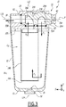
- Filter 10 is shown alone in figures 2 to 8 .
- This filter 10 comprises a cup 12, defining a reception volume V12, and a filter element 14 housed in the reception volume V12.
- the filter element 14 is a filter cartridge of rigid or partially rigid cylindrical shape.
- the filter element 14 comprises, for example, a rigid disc-shaped bottom 14A and a frame not shown, while a canvas 14B of the cylindrical cartridge is made of a flexible and porous material.
- the material of the fabric 14B can be natural or synthetic, depending on the nature of the liquid product to be filtered. It can, for example, be stainless steel, polymer or cellulose.
- the cup 12 is made of a material which takes into account the nature of the liquid product which must pass through the filter element.
- the cup is made of metal, preferably stainless steel. It has, for example, a fixed capacity of between one and two liters.
- the filter 10 further comprises a valve 20 integrated in a head 22.
- the cup is reversibly assembled with the head 22.
- the components 12 and 22 can be screwed together, snapped or assembled by a bayonet-type mechanism or with flanges.
- the filter element is, for its part, removably attached to the lower face 221 of the head 22, and is held by a mechanical fastening system, for example screw, clip, etc.
- the bucket 12 is in symmetry of revolution about a longitudinal axis L12 of the cup 12.
- the filter element 14 is in symmetry of revolution about a longitudinal axis L14 of this element.
- the longitudinal axes L12 and L14 are coincident and parallel to the Z axis.
- the longitudinal axes L12 and L14 are included in the section plane III of the figure 2 .
- the longitudinal axis L12 of the cup 12 and the longitudinal axis L14 of the filter element 14 are not the same.
- the cup 12 comprises a bottom 13 pierced with a purge orifice 31, preferably coaxial with the longitudinal axis L12.
- a purge orifice 31 is closed by a plug 32 or the like.
- the filter 10 further comprises a pipe 16 for admission of liquid product intended to be connected to the portion 54 and a pipe 18 for discharging liquid product intended to be connected to the portion 56.
- the pipes 16 and 18 have cylindrical sections and the longitudinal axes L16 and L18 of the pipes 16 and 18 are respectively parallel to the Y and X axes of the orthonormal frame.
- the longitudinal axes L16 and L18 of the pipes 16 and 18 are included in the section plane IV of the figure 2 .
- the valve 20 comprises at least one ball valve.
- the valve 20 is movable in rotation, by causing the ball to pivot about a pivot axis P parallel to the axis X, the pivot axis P corresponding to the intersection between the planes III and IV of the figure 2 .
- the pivot axis P is defined by the body 23 of the valve 20 which, in practice, consists of a part of the head 22.
- the valve 20 comprises two ball valves 24A and 24B integral with one another.
- the bushels 24A and 24B are formed by a single piece.
- Each ball 24A and 24B is a part with a spherical outer casing, partially hollowed out, such as a ball pierced by a duct 26A or 26B opening into two separate orifices specific to each valve 24A or 24B.
- the conduits 26A and 26B are bent, each preferably forming an angle of 90 °, and have circular sections of diameters substantially equal to those of the pipes 16 and 18.
- the diameters of the conduits 26A and 26B are smaller than those of the pipes 16 and 18.
- the bent conduits 26A and 26B each respectively comprise two rectilinear portions 25A, 27A and 25B, 27B and a respective right angle bend 28A and 28B.
- first plug 24A is crossed by the conduit 26A, formed by the rectilinear portions 25A and 27A connected to each other by the elbow 28A.
- second plug 24B is crossed by the duct 26B, formed by the rectilinear portions 25B and 27B connected to each other by the elbow 28B.
- the body 23 defines a housing accommodating the plugs 24A and 24B of the valve 20.
- the housing is formed of two spherical cavities 23A and 23B which open into one another and each respectively receive a ball valve 24A or 24B.
- the pipes 16 and 18 are formed by the body 23 of the head 22.
- the cavity 23A accommodating the first ball valve 24A is fluidly connected to the intake pipe 16 while the cavity 23B accommodating the second ball valve 24B is fluidly connected to the discharge tubing 18.
- the filter 10 also includes at least one air inlet port.
- the filter 10 here comprises two air inlet orifices 36A and 36 B, formed in a wall 232 of the body 23, this wall being parallel to the plane formed by the axes X and Z.
- the orifices 36A and 36B open out. respectively in the cavities 23A and 23B, each facing a ball valve 24A or 24B.
- the number of air inlet openings and / or their location may be different, provided that they fulfill their function, described below.
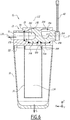
- At least one of the ball valves 24A or 24B is provided with a groove 34A or 34B for placing the receiving volume V12 in communication with the air inlet port 36, which is adjacent thereto, when the valve 20 is in its second position, as visible at the figure 8 .
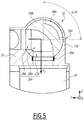
- each plug 24A and 24B includes its own groove, the groove 34A of the plug 24A being visible at figures 5 and 8 , while the two grooves 34A and 34B are visible at the figure 6 .
- the grooves 34A and 34B hollow out to a small depth the surfaces of the plugs 24A and 24B, so as not to open into the conduits 26A and 26B.
- the two grooves 34 are identical or almost identical to one another.
- each groove 34A and 34 B extends over 90 ° on the surface of the plug 24A or 24B on which it is formed on which it is formed.
- Seals 51A and 51B are arranged in the body 23 at the level of the junctions between the intake manifold 16 and the ball valves 24A and 24B.
- a seal 53 is disposed in the body 23, at the level of the junction between the discharge pipe 18 and the ball valve 24B.
- Seals 55A and 55B are arranged in the body 23 at the level of the junctions between the volume V12 and the plugs 24A and 24B.
- the joints 51A, 51B, 55A and 55B have a geometry adapted to the spherical profile of the plugs 24A and 24B.
- the seals are integral with the body 23 of the head 22; they are therefore not rotated during the pivoting of the plugs 24A and 24B.
- a manual control member formed here by a lever 40, is integral, in rotation about the pivot axis P, of the first valve 24A and makes it possible to actuate the valve 20.
- the valve 20 is configured to selectively take two distinct positions.
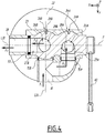
- valve 20 In its first position represented in figures 1 to 5 , the valve 20 connects the intake manifold 16 to the receiving volume V12, through the elbow duct 26A, and this receiving volume V12 to the discharge pipe 18, through the elbow duct 26B. In its second position shown in figures 6 to 8 , the valve 20 directly connects the intake pipe 16 to the discharge pipe 18, through the bent pipe 26B. The second position of the valve 20 makes it possible to isolate the receiving volume V12 from the two pipes 16 and 18. Thus, when the valve 20 is in its second position, the liquid product circulates between the inlet pipe 16 and the pipe d. 'discharge 18 without passing either into the cup 12 or through the filter element 14, this configuration corresponds to the "bypass".
- the arrows F1 and F2 here respectively indicate the directions and the direction of the flow entering the filter 10 through the intake pipe 16 and leaving through the discharge pipe 18.
- a rotation of amplitude equal to 90 ° carried out by manual actuation of the handle 40, allows the valve 20 to switch from its first position to its second position, and vice versa. Since the ball valves 24A and 24B are integral with one another, they are simultaneously pivoted about the pivot axis P when the lever 40 is actuated.
- the straight portion 25A In the first position of the valve 20, the straight portion 25A is parallel to the Y axis and connected with the intake manifold 16, the straight portion 27A is parallel to the Z axis, thus allowing the liquid product to flow. flow into volume V12 of cup 12, following a path represented by arrows F1 and F3 on the figures 3 to 5 .
- the product then passes through the filter element 14, as represented by the arrow F4 on the figure 3 , then passes through the second valve 24B following the arrow F5 before being discharged through the orifice 18 following the arrow F2.
- the straight portion 25B is then parallel to the Z axis and the straight portion 27B is parallel to the X axis and connected with the discharge pipe 18.
- the straight portion 27A is parallel to the Y axis and connected with the intake manifold 16
- the straight portion 25A is parallel to the Z axis and disposed opposite a wall 234 formed by the body 23, on the side of the head 22 opposite the cup 12.
- the liquid product is forced to pass directly through the conduit 26B of the second valve 24B, by following the arrows F1 and F2 visible in particular on the figure 7 .
- the straight portion 25B is here parallel to the Y axis and connected with the intake manifold 16, the straight portion 27B is here parallel to the X axis and connected with the discharge pipe 18.
- the straight portion 27B is constantly parallel to the axis X.
- the position of the handle 40 indicates the degree of opening or closing of the internal plug (s) 24A and 24B at the head 22.
- the valve 20 When the handle is oriented along the Y axis, therefore parallel to the axis L16, the valve 20 is in its first position, the liquid product then passes through pipe 26A, into cup 12 and through filter element 14, before being discharged through orifice 18 through pipe 26B of the second valve 24B.
- the lever 40 When the lever 40 is oriented parallel to the Z axis, therefore perpendicular to the axis L16, the valve 20 is in its second position, the liquid product circulates in the bypass formed by the bent pipe 26B.
- the grooves 34A and 34B create a passage between the air inlet openings 36A and 36B and the receiving volume V12, then making it possible to put the inside of the cup 12 at atmospheric pressure and to perform a purge. of the filter 10 through the drain hole 31 of the bottom 13, after having removed the plug 32, which is represented by the arrow F6 at the figure 6 .
- the valve 20 After having closed the orifice 31 with the button 32, the valve 20 is moved back to its first position, which makes the filter 10 operational again. So the change of filter element 14 can take place quickly and easily, without major disruption of the operation of the installation 1.
- conduits 26A and 26B are used in the two positions of the valve 20, they are permanently wetted by the liquid product. There is therefore no risk of deposits forming in these conduits, unlike a bypass pipe used occasionally. The filter change operation therefore takes place without revealing any retention zone where the product would not be renewed and where it could deteriorate.
- the inlet pipe of the filter 10 may be the pipe 18, while the discharge pipe is the pipe 16. This is for example the case of so-called "pocket” filters. .
- the direction of arrows F1 to F5 is then reversed; the arrows F1 and F2 are swapped, as are the arrows F3 and F5.
- the invention is not limited to the case where the liquid product is a coating product.
- the filter 10 can be used in particular to filter an oil, for example for an engine, a cleaning product, water leaving a well, or a more viscous product such as glue, paste, sealant, anti-gravel or soundproofing.
- valve 20 is motorized, in particular in order to be remotely controlled or robotized, which makes it possible to actuate the valve remotely.
- the plugs 24A and 24B are cylindrical plugs.
- the valve 20 comprises a single cylindrical or spherical valve, which is then advantageously multi-channel.
Landscapes
- Chemical & Material Sciences (AREA)
- Chemical Kinetics & Catalysis (AREA)
- Engineering & Computer Science (AREA)
- General Engineering & Computer Science (AREA)
- Mechanical Engineering (AREA)
- Filtration Of Liquid (AREA)
- Filtering Of Dispersed Particles In Gases (AREA)
- Loading And Unloading Of Fuel Tanks Or Ships (AREA)
- Details Of Reciprocating Pumps (AREA)
Claims (8)
- Filter (10) für flüssiges oder viskoses Produkt, dieser Filter umfassend ein Filterelement (14) und einen Becher (12), der ein Aufnahmevolumen (V12) definiert, das das Filterelement aufnimmt, der Filter (10) umfassend einen Einlassstutzen (16) für flüssiges oder viskoses Produkt und einen Auslassstutzen (18) für flüssiges oder viskoses Produkt, der Filter (10) umfassend ein Ventil (20), das konfiguriert ist, um Folgendes einzunehmen:- eine erste Position, in der das Ventil (20) den Einlassstutzen (16) mit dem Aufnahmevolumen (V12) und dieses Aufnahmevolumen (V12) mit dem Auslassstutzen (18) verbindet; und- eine zweite Position, in der das Ventil (20) den Einlassverteiler (16) mit dem Auslassverteiler (18) verbindet und das Aufnahmevolumen (V12) in Bezug auf die zwei Stutzen (16, 18) trenntdadurch gekennzeichnet, dass das Ventil (20) zwei zylindrische oder kugelförmige Stopfen (24A, 24B) umfasst, wovon ein erster zylindrischer oder kugelförmiger Stopfen (24A) eine erste Leitung (26A) umfasst, die den Einlassstutzen (16) mit dem Aufnahmevolumen (V12) verbindet, wenn das Ventil (20) in seiner ersten Position ist, und die ein totes Stück bildet, wenn das Ventil (20) in seiner zweiten Position ist, und einen zweiten zylindrischen oder kugelförmigen Stopfen (24B), der eine zweite Leitung (26B) umfasst, die das Aufnahmevolumen (V12) mit dem Auslassstutzen (18) verbindet, wenn das Ventil (20) in seiner ersten Position ist, und der den Einlassstutzen (16) mit der Auslassleitung (18) verbindet, wenn das Ventil (20) in seiner zweiten Position ist.
- Filter nach dem vorherigen Anspruch, dadurch gekennzeichnet, dass der Filter (10) mindestens eine Lufteinlassöffnung (36A, 36B) und eine Entlüftungsöffnung (31) umfasst.
- Filter nach Anspruch 2, dadurch gekennzeichnet, dass mindestens ein kugelförmiger Stopfen (24A, 24B) eine Nut (34A, 34B) aufweist, um das Aufnahmevolumen (V12) mit der Lufteinlassöffnung (36A, 36B) in Kommunikation zu bringen, wenn das Ventil (20) in seiner zweiten Position ist.
- Filter nach einem der vorherigen Ansprüche, dadurch gekennzeichnet, dass er ein Element (40) zur manuellen Steuerung der Position des Ventils (20) umfasst.
- Filter nach einem der vorherigen Ansprüche, dadurch gekennzeichnet, dass das Ventil (20) zwischen seiner ersten Position und seiner zweiten Position und umgekehrt durch eine Drehung, deren Amplitude vorzugsweise gleich 90° ist, um eine Schwenkachse (P), die durch einen Körper (23) des Ventils definiert ist, beweglich ist.
- Filter nach einem der vorherigen Ansprüche, dadurch gekennzeichnet, dass das Ventil (20) in einen Kopf (22) integriert ist, der abnehmbar an dem Becher (12) montiert ist.
- Filter nach dem vorherigen Anspruch, dadurch gekennzeichnet, dass das Filterelement (14) eine zylindrische Patrone ist, die abnehmbar auf dem Kopf (22) montiert ist.
- Sprühanlage mit einem Behälter (2), für ein flüssiges oder viskoses Produkt, eine Pumpe (4) und einer Sprühvorrichtung (6) umfasst, dadurch gekennzeichnet, dass die Anlage (1) einen Filter (10) für ein flüssiges oder viskoses Produkt nach einem der vorherigen Ansprüche umfasst.
Applications Claiming Priority (1)
| Application Number | Priority Date | Filing Date | Title |
|---|---|---|---|
| FR1900962A FR3092501B1 (fr) | 2019-01-31 | 2019-01-31 | Filtre pour produit liquide ou visqueux et installation de pulvérisation comprenant un tel filtre |
Publications (2)
| Publication Number | Publication Date |
|---|---|
| EP3689435A1 EP3689435A1 (de) | 2020-08-05 |
| EP3689435B1 true EP3689435B1 (de) | 2021-10-06 |
Family
ID=66867463
Family Applications (1)
| Application Number | Title | Priority Date | Filing Date |
|---|---|---|---|
| EP20154641.3A Active EP3689435B1 (de) | 2019-01-31 | 2020-01-30 | Filter für flüssiges oder viskoses produkt, und sprühanlage, die einen solchen filter umfasst |
Country Status (7)
| Country | Link |
|---|---|
| US (1) | US10974178B2 (de) |
| EP (1) | EP3689435B1 (de) |
| JP (1) | JP7477976B2 (de) |
| KR (1) | KR102944373B1 (de) |
| CN (1) | CN111495003B (de) |
| ES (1) | ES2901894T3 (de) |
| FR (1) | FR3092501B1 (de) |
Family Cites Families (15)
| Publication number | Priority date | Publication date | Assignee | Title |
|---|---|---|---|---|
| US2602697A (en) * | 1949-02-23 | 1952-07-08 | Paul F Otto | Mixer device |
| US2604446A (en) * | 1949-09-19 | 1952-07-22 | Bruner Corp | Water conditioning device |
| US3420375A (en) * | 1966-03-21 | 1969-01-07 | Marvel Eng Co | Filter with automatic bypass-shutoff |
| CA962915A (en) * | 1971-04-05 | 1975-02-18 | Sam Close | Valve for a filter |
| JPS5484444U (de) * | 1977-11-26 | 1979-06-15 | ||
| FR2472707A1 (fr) * | 1979-12-31 | 1981-07-03 | Ferodo Sa | Dispositif pour la commande de l'alimentation en liquide d'un appareil, notamment d'un echangeur de chaleur, en particulier pour vehicule automobile |
| JPS59150581U (ja) * | 1983-03-28 | 1984-10-08 | 天昇電気工業株式会社 | 簡易浄水器 |
| US5152321A (en) * | 1991-10-07 | 1992-10-06 | Ecowater Systems, Inc. | Bypass valve |
| DK90694A (da) * | 1994-08-03 | 1996-02-04 | Heco International A S | Filter, især magnetfilter, til kontinuert drift |
| US5931196A (en) * | 1998-04-29 | 1999-08-03 | United States Filter Corporation | Bypass valve |
| US6746600B2 (en) * | 2001-10-31 | 2004-06-08 | Arvin Technologies, Inc. | Fluid filter with integrated cooler |
| JP5052859B2 (ja) * | 2006-10-23 | 2012-10-17 | 株式会社日本技術開発センター | 浄水器用容器 |
| US8888998B2 (en) * | 2010-08-09 | 2014-11-18 | Paragon Water Systems, Inc. | Bypass valve for water filter system |
| CA2906568A1 (en) * | 2013-03-15 | 2014-09-25 | Mann+Hummel Purolater Filters Llc | Spherical contact ball joint style spool relief valve |
| IT201600119549A1 (it) * | 2016-11-25 | 2018-05-25 | Euroacque S R L | Dispositivo filtro defangatore |
-
2019
- 2019-01-31 FR FR1900962A patent/FR3092501B1/fr not_active Expired - Fee Related
-
2020
- 2020-01-24 JP JP2020009943A patent/JP7477976B2/ja active Active
- 2020-01-28 US US16/775,124 patent/US10974178B2/en active Active
- 2020-01-30 ES ES20154641T patent/ES2901894T3/es active Active
- 2020-01-30 KR KR1020200010871A patent/KR102944373B1/ko active Active
- 2020-01-30 EP EP20154641.3A patent/EP3689435B1/de active Active
- 2020-01-31 CN CN202010077668.1A patent/CN111495003B/zh active Active
Also Published As
| Publication number | Publication date |
|---|---|
| CN111495003A (zh) | 2020-08-07 |
| JP2020124703A (ja) | 2020-08-20 |
| KR102944373B1 (ko) | 2026-03-25 |
| ES2901894T3 (es) | 2022-03-24 |
| CN111495003B (zh) | 2023-04-28 |
| KR20200095407A (ko) | 2020-08-10 |
| FR3092501B1 (fr) | 2022-08-26 |
| US20200246734A1 (en) | 2020-08-06 |
| EP3689435A1 (de) | 2020-08-05 |
| FR3092501A1 (fr) | 2020-08-14 |
| JP7477976B2 (ja) | 2024-05-02 |
| US10974178B2 (en) | 2021-04-13 |
Similar Documents
| Publication | Publication Date | Title |
|---|---|---|
| WO2017064438A1 (fr) | Vanne fluidique a hysteresis | |
| EP3785802B1 (de) | Ventil, system zur auftragung eines beschichtungsprodukts, das ein solches ventil umfasst, und werkzeug für dessen montage und demontage | |
| FR2536458A1 (fr) | Moteur a combustion interne a moyens de lubrification simplifiee | |
| EP3689435B1 (de) | Filter für flüssiges oder viskoses produkt, und sprühanlage, die einen solchen filter umfasst | |
| EP3724473B1 (de) | Abschnitt einer flüssigkeitsabflussleitung für eine turbomaschine | |
| WO1987007352A1 (fr) | Vanne de distribution de liquide | |
| EP0289444B1 (de) | Filterapparat | |
| FR2957999A1 (fr) | Piston avec un conduit sous joint | |
| EP3177571B1 (de) | Wasserbehandlungsvorrichtung mit hoher kapazität | |
| FR3105938A1 (fr) | Vanne, système d’application de produit de revêtement comprenant une telle vanne et outil dédié de montage et démontage | |
| CA3049216A1 (fr) | Ensemble de production d'energie et procede de purge de l'eau contenue dans un reservoir d'aeronef associe | |
| CA3049218A1 (fr) | Systeme et necessaire de purge d'un reservoir et procedes de purge et de montage associes | |
| FR2893379A1 (fr) | Vanne coaxiale d'interception destinee a etre utilisee dans des installations d'air comprime | |
| EP2532405B1 (de) | Kraftstofffilter mit Wasserablasselement und Filterelement für einen solchen Filter | |
| EP1737315A2 (de) | Materialausgabevorrichtung mit drehverschluss | |
| FR2977805A1 (fr) | Unite de filtration de lubrifiant pour transmission de vehicule automobile | |
| EP3446192B1 (de) | Mischeinheit und mischarmatur mit solch einer mischeinheit | |
| FR2670270A1 (fr) | Poste de purge monobloc a robinets d'isolement incorpores. | |
| FR2843052A1 (fr) | Installation de peinture nettoyee par ecouvillon | |
| FR2560695A1 (fr) | Regulateur de pression, en particulier pour une installation de pulverisation d'un liquide de traitement | |
| FR2863731A1 (fr) | Cartouche thermostatique avec clapets anti-retour integres et installation la comportant | |
| EP3393965B1 (de) | Ausrüstung mit einem einsetzbaren koaxialventil zur übertragung eines fluid in ein reservoir und verfahren | |
| FR2844731A1 (fr) | Boitier de lavage pour nez de vidange d'un tank refroidisseur de lait | |
| FR2699425A1 (fr) | Dispositif pour injecter un gaz, notamment de l'air, dans un courant de liquide, en particulier dans une solution destinée à mousser. | |
| FR2757909A1 (fr) | Dispositif venturi et application d'un tel dispositif a une installation de dosage |
Legal Events
| Date | Code | Title | Description |
|---|---|---|---|
| PUAI | Public reference made under article 153(3) epc to a published international application that has entered the european phase |
Free format text: ORIGINAL CODE: 0009012 |
|
| STAA | Information on the status of an ep patent application or granted ep patent |
Free format text: STATUS: THE APPLICATION HAS BEEN PUBLISHED |
|
| AK | Designated contracting states |
Kind code of ref document: A1 Designated state(s): AL AT BE BG CH CY CZ DE DK EE ES FI FR GB GR HR HU IE IS IT LI LT LU LV MC MK MT NL NO PL PT RO RS SE SI SK SM TR |
|
| AX | Request for extension of the european patent |
Extension state: BA ME |
|
| STAA | Information on the status of an ep patent application or granted ep patent |
Free format text: STATUS: REQUEST FOR EXAMINATION WAS MADE |
|
| 17P | Request for examination filed |
Effective date: 20210111 |
|
| RBV | Designated contracting states (corrected) |
Designated state(s): AL AT BE BG CH CY CZ DE DK EE ES FI FR GB GR HR HU IE IS IT LI LT LU LV MC MK MT NL NO PL PT RO RS SE SI SK SM TR |
|
| GRAP | Despatch of communication of intention to grant a patent |
Free format text: ORIGINAL CODE: EPIDOSNIGR1 |
|
| STAA | Information on the status of an ep patent application or granted ep patent |
Free format text: STATUS: GRANT OF PATENT IS INTENDED |
|
| INTG | Intention to grant announced |
Effective date: 20210511 |
|
| GRAS | Grant fee paid |
Free format text: ORIGINAL CODE: EPIDOSNIGR3 |
|
| GRAA | (expected) grant |
Free format text: ORIGINAL CODE: 0009210 |
|
| STAA | Information on the status of an ep patent application or granted ep patent |
Free format text: STATUS: THE PATENT HAS BEEN GRANTED |
|
| AK | Designated contracting states |
Kind code of ref document: B1 Designated state(s): AL AT BE BG CH CY CZ DE DK EE ES FI FR GB GR HR HU IE IS IT LI LT LU LV MC MK MT NL NO PL PT RO RS SE SI SK SM TR |
|
| REG | Reference to a national code |
Ref country code: GB Ref legal event code: FG4D Free format text: NOT ENGLISH |
|
| REG | Reference to a national code |
Ref country code: CH Ref legal event code: EP Ref country code: AT Ref legal event code: REF Ref document number: 1435733 Country of ref document: AT Kind code of ref document: T Effective date: 20211015 |
|
| REG | Reference to a national code |
Ref country code: DE Ref legal event code: R096 Ref document number: 602020000655 Country of ref document: DE |
|
| REG | Reference to a national code |
Ref country code: IE Ref legal event code: FG4D Free format text: LANGUAGE OF EP DOCUMENT: FRENCH |
|
| REG | Reference to a national code |
Ref country code: LT Ref legal event code: MG9D |
|
| REG | Reference to a national code |
Ref country code: NL Ref legal event code: MP Effective date: 20211006 |
|
| REG | Reference to a national code |
Ref country code: AT Ref legal event code: MK05 Ref document number: 1435733 Country of ref document: AT Kind code of ref document: T Effective date: 20211006 |
|
| REG | Reference to a national code |
Ref country code: ES Ref legal event code: FG2A Ref document number: 2901894 Country of ref document: ES Kind code of ref document: T3 Effective date: 20220324 |
|
| PG25 | Lapsed in a contracting state [announced via postgrant information from national office to epo] |
Ref country code: RS Free format text: LAPSE BECAUSE OF FAILURE TO SUBMIT A TRANSLATION OF THE DESCRIPTION OR TO PAY THE FEE WITHIN THE PRESCRIBED TIME-LIMIT Effective date: 20211006 Ref country code: LT Free format text: LAPSE BECAUSE OF FAILURE TO SUBMIT A TRANSLATION OF THE DESCRIPTION OR TO PAY THE FEE WITHIN THE PRESCRIBED TIME-LIMIT Effective date: 20211006 Ref country code: FI Free format text: LAPSE BECAUSE OF FAILURE TO SUBMIT A TRANSLATION OF THE DESCRIPTION OR TO PAY THE FEE WITHIN THE PRESCRIBED TIME-LIMIT Effective date: 20211006 Ref country code: BG Free format text: LAPSE BECAUSE OF FAILURE TO SUBMIT A TRANSLATION OF THE DESCRIPTION OR TO PAY THE FEE WITHIN THE PRESCRIBED TIME-LIMIT Effective date: 20220106 Ref country code: AT Free format text: LAPSE BECAUSE OF FAILURE TO SUBMIT A TRANSLATION OF THE DESCRIPTION OR TO PAY THE FEE WITHIN THE PRESCRIBED TIME-LIMIT Effective date: 20211006 |
|
| PG25 | Lapsed in a contracting state [announced via postgrant information from national office to epo] |
Ref country code: IS Free format text: LAPSE BECAUSE OF FAILURE TO SUBMIT A TRANSLATION OF THE DESCRIPTION OR TO PAY THE FEE WITHIN THE PRESCRIBED TIME-LIMIT Effective date: 20220206 Ref country code: SE Free format text: LAPSE BECAUSE OF FAILURE TO SUBMIT A TRANSLATION OF THE DESCRIPTION OR TO PAY THE FEE WITHIN THE PRESCRIBED TIME-LIMIT Effective date: 20211006 Ref country code: PT Free format text: LAPSE BECAUSE OF FAILURE TO SUBMIT A TRANSLATION OF THE DESCRIPTION OR TO PAY THE FEE WITHIN THE PRESCRIBED TIME-LIMIT Effective date: 20220207 Ref country code: PL Free format text: LAPSE BECAUSE OF FAILURE TO SUBMIT A TRANSLATION OF THE DESCRIPTION OR TO PAY THE FEE WITHIN THE PRESCRIBED TIME-LIMIT Effective date: 20211006 Ref country code: NO Free format text: LAPSE BECAUSE OF FAILURE TO SUBMIT A TRANSLATION OF THE DESCRIPTION OR TO PAY THE FEE WITHIN THE PRESCRIBED TIME-LIMIT Effective date: 20220106 Ref country code: NL Free format text: LAPSE BECAUSE OF FAILURE TO SUBMIT A TRANSLATION OF THE DESCRIPTION OR TO PAY THE FEE WITHIN THE PRESCRIBED TIME-LIMIT Effective date: 20211006 Ref country code: LV Free format text: LAPSE BECAUSE OF FAILURE TO SUBMIT A TRANSLATION OF THE DESCRIPTION OR TO PAY THE FEE WITHIN THE PRESCRIBED TIME-LIMIT Effective date: 20211006 Ref country code: HR Free format text: LAPSE BECAUSE OF FAILURE TO SUBMIT A TRANSLATION OF THE DESCRIPTION OR TO PAY THE FEE WITHIN THE PRESCRIBED TIME-LIMIT Effective date: 20211006 Ref country code: GR Free format text: LAPSE BECAUSE OF FAILURE TO SUBMIT A TRANSLATION OF THE DESCRIPTION OR TO PAY THE FEE WITHIN THE PRESCRIBED TIME-LIMIT Effective date: 20220107 |
|
| REG | Reference to a national code |
Ref country code: DE Ref legal event code: R097 Ref document number: 602020000655 Country of ref document: DE |
|
| PG25 | Lapsed in a contracting state [announced via postgrant information from national office to epo] |
Ref country code: SM Free format text: LAPSE BECAUSE OF FAILURE TO SUBMIT A TRANSLATION OF THE DESCRIPTION OR TO PAY THE FEE WITHIN THE PRESCRIBED TIME-LIMIT Effective date: 20211006 Ref country code: SK Free format text: LAPSE BECAUSE OF FAILURE TO SUBMIT A TRANSLATION OF THE DESCRIPTION OR TO PAY THE FEE WITHIN THE PRESCRIBED TIME-LIMIT Effective date: 20211006 Ref country code: RO Free format text: LAPSE BECAUSE OF FAILURE TO SUBMIT A TRANSLATION OF THE DESCRIPTION OR TO PAY THE FEE WITHIN THE PRESCRIBED TIME-LIMIT Effective date: 20211006 Ref country code: EE Free format text: LAPSE BECAUSE OF FAILURE TO SUBMIT A TRANSLATION OF THE DESCRIPTION OR TO PAY THE FEE WITHIN THE PRESCRIBED TIME-LIMIT Effective date: 20211006 Ref country code: DK Free format text: LAPSE BECAUSE OF FAILURE TO SUBMIT A TRANSLATION OF THE DESCRIPTION OR TO PAY THE FEE WITHIN THE PRESCRIBED TIME-LIMIT Effective date: 20211006 Ref country code: CZ Free format text: LAPSE BECAUSE OF FAILURE TO SUBMIT A TRANSLATION OF THE DESCRIPTION OR TO PAY THE FEE WITHIN THE PRESCRIBED TIME-LIMIT Effective date: 20211006 |
|
| PLBE | No opposition filed within time limit |
Free format text: ORIGINAL CODE: 0009261 |
|
| STAA | Information on the status of an ep patent application or granted ep patent |
Free format text: STATUS: NO OPPOSITION FILED WITHIN TIME LIMIT |
|
| PG25 | Lapsed in a contracting state [announced via postgrant information from national office to epo] |
Ref country code: MC Free format text: LAPSE BECAUSE OF FAILURE TO SUBMIT A TRANSLATION OF THE DESCRIPTION OR TO PAY THE FEE WITHIN THE PRESCRIBED TIME-LIMIT Effective date: 20211006 |
|
| 26N | No opposition filed |
Effective date: 20220707 |
|
| REG | Reference to a national code |
Ref country code: BE Ref legal event code: MM Effective date: 20220131 |
|
| PG25 | Lapsed in a contracting state [announced via postgrant information from national office to epo] |
Ref country code: LU Free format text: LAPSE BECAUSE OF NON-PAYMENT OF DUE FEES Effective date: 20220130 Ref country code: AL Free format text: LAPSE BECAUSE OF FAILURE TO SUBMIT A TRANSLATION OF THE DESCRIPTION OR TO PAY THE FEE WITHIN THE PRESCRIBED TIME-LIMIT Effective date: 20211006 |
|
| PG25 | Lapsed in a contracting state [announced via postgrant information from national office to epo] |
Ref country code: SI Free format text: LAPSE BECAUSE OF FAILURE TO SUBMIT A TRANSLATION OF THE DESCRIPTION OR TO PAY THE FEE WITHIN THE PRESCRIBED TIME-LIMIT Effective date: 20211006 Ref country code: BE Free format text: LAPSE BECAUSE OF NON-PAYMENT OF DUE FEES Effective date: 20220131 |
|
| PG25 | Lapsed in a contracting state [announced via postgrant information from national office to epo] |
Ref country code: IE Free format text: LAPSE BECAUSE OF NON-PAYMENT OF DUE FEES Effective date: 20220130 |
|
| PG25 | Lapsed in a contracting state [announced via postgrant information from national office to epo] |
Ref country code: MK Free format text: LAPSE BECAUSE OF FAILURE TO SUBMIT A TRANSLATION OF THE DESCRIPTION OR TO PAY THE FEE WITHIN THE PRESCRIBED TIME-LIMIT Effective date: 20211006 Ref country code: CY Free format text: LAPSE BECAUSE OF FAILURE TO SUBMIT A TRANSLATION OF THE DESCRIPTION OR TO PAY THE FEE WITHIN THE PRESCRIBED TIME-LIMIT Effective date: 20211006 |
|
| PG25 | Lapsed in a contracting state [announced via postgrant information from national office to epo] |
Ref country code: HU Free format text: LAPSE BECAUSE OF FAILURE TO SUBMIT A TRANSLATION OF THE DESCRIPTION OR TO PAY THE FEE WITHIN THE PRESCRIBED TIME-LIMIT; INVALID AB INITIO Effective date: 20200130 |
|
| PG25 | Lapsed in a contracting state [announced via postgrant information from national office to epo] |
Ref country code: MT Free format text: LAPSE BECAUSE OF FAILURE TO SUBMIT A TRANSLATION OF THE DESCRIPTION OR TO PAY THE FEE WITHIN THE PRESCRIBED TIME-LIMIT Effective date: 20211006 |
|
| PGFP | Annual fee paid to national office [announced via postgrant information from national office to epo] |
Ref country code: CH Payment date: 20250201 Year of fee payment: 6 |
|
| REG | Reference to a national code |
Ref country code: CH Ref legal event code: R18 Free format text: ST27 STATUS EVENT CODE: U-0-0-R10-R18 (AS PROVIDED BY THE NATIONAL OFFICE) Effective date: 20260106 |
|
| PGFP | Annual fee paid to national office [announced via postgrant information from national office to epo] |
Ref country code: GB Payment date: 20260127 Year of fee payment: 7 |
|
| PGFP | Annual fee paid to national office [announced via postgrant information from national office to epo] |
Ref country code: ES Payment date: 20260209 Year of fee payment: 7 |
|
| PGFP | Annual fee paid to national office [announced via postgrant information from national office to epo] |
Ref country code: DE Payment date: 20260114 Year of fee payment: 7 |
|
| PGFP | Annual fee paid to national office [announced via postgrant information from national office to epo] |
Ref country code: IT Payment date: 20260107 Year of fee payment: 7 |
|
| PGFP | Annual fee paid to national office [announced via postgrant information from national office to epo] |
Ref country code: FR Payment date: 20260128 Year of fee payment: 7 |
|
| PGFP | Annual fee paid to national office [announced via postgrant information from national office to epo] |
Ref country code: TR Payment date: 20260126 Year of fee payment: 7 |