EP3178754B1 - Conteneur gonflable de transport d'un fluide biopharmaceutique et système et procédé mettant en oeuvre un tel conteneur - Google Patents
Conteneur gonflable de transport d'un fluide biopharmaceutique et système et procédé mettant en oeuvre un tel conteneur Download PDFInfo
- Publication number
- EP3178754B1 EP3178754B1 EP15306951.3A EP15306951A EP3178754B1 EP 3178754 B1 EP3178754 B1 EP 3178754B1 EP 15306951 A EP15306951 A EP 15306951A EP 3178754 B1 EP3178754 B1 EP 3178754B1
- Authority
- EP
- European Patent Office
- Prior art keywords
- container
- wall
- biopharmaceutical fluid
- internal cavity
- internal
- Prior art date
- Legal status (The legal status is an assumption and is not a legal conclusion. Google has not performed a legal analysis and makes no representation as to the accuracy of the status listed.)
- Active
Links
Images


Classifications
-
- B—PERFORMING OPERATIONS; TRANSPORTING
- B65—CONVEYING; PACKING; STORING; HANDLING THIN OR FILAMENTARY MATERIAL
- B65D—CONTAINERS FOR STORAGE OR TRANSPORT OF ARTICLES OR MATERIALS, e.g. BAGS, BARRELS, BOTTLES, BOXES, CANS, CARTONS, CRATES, DRUMS, JARS, TANKS, HOPPERS, FORWARDING CONTAINERS; ACCESSORIES, CLOSURES, OR FITTINGS THEREFOR; PACKAGING ELEMENTS; PACKAGES
- B65D81/00—Containers, packaging elements, or packages, for contents presenting particular transport or storage problems, or adapted to be used for non-packaging purposes after removal of contents
- B65D81/02—Containers, packaging elements, or packages, for contents presenting particular transport or storage problems, or adapted to be used for non-packaging purposes after removal of contents specially adapted to protect contents from mechanical damage
- B65D81/03—Wrappers or envelopes with shock-absorbing properties, e.g. bubble films
-
- A—HUMAN NECESSITIES
- A01—AGRICULTURE; FORESTRY; ANIMAL HUSBANDRY; HUNTING; TRAPPING; FISHING
- A01N—PRESERVATION OF BODIES OF HUMANS OR ANIMALS OR PLANTS OR PARTS THEREOF; BIOCIDES, e.g. AS DISINFECTANTS, AS PESTICIDES OR AS HERBICIDES; PEST REPELLANTS OR ATTRACTANTS; PLANT GROWTH REGULATORS
- A01N1/00—Preservation of bodies of humans or animals, or parts thereof
- A01N1/10—Preservation of living parts
- A01N1/14—Mechanical aspects of preservation; Apparatus or containers therefor
- A01N1/142—Apparatus
- A01N1/144—Apparatus for temperature control, e.g. refrigerators or freeze-drying apparatus
-
- A—HUMAN NECESSITIES
- A01—AGRICULTURE; FORESTRY; ANIMAL HUSBANDRY; HUNTING; TRAPPING; FISHING
- A01N—PRESERVATION OF BODIES OF HUMANS OR ANIMALS OR PLANTS OR PARTS THEREOF; BIOCIDES, e.g. AS DISINFECTANTS, AS PESTICIDES OR AS HERBICIDES; PEST REPELLANTS OR ATTRACTANTS; PLANT GROWTH REGULATORS
- A01N1/00—Preservation of bodies of humans or animals, or parts thereof
- A01N1/10—Preservation of living parts
- A01N1/14—Mechanical aspects of preservation; Apparatus or containers therefor
- A01N1/146—Non-refrigerated containers specially adapted for transporting or storing living parts whilst preserving
- A01N1/148—Non-refrigerated containers specially adapted for transporting or storing living parts whilst preserving with provisions specially adapted for transporting
-
- A—HUMAN NECESSITIES
- A61—MEDICAL OR VETERINARY SCIENCE; HYGIENE
- A61J—CONTAINERS SPECIALLY ADAPTED FOR MEDICAL OR PHARMACEUTICAL PURPOSES; DEVICES OR METHODS SPECIALLY ADAPTED FOR BRINGING PHARMACEUTICAL PRODUCTS INTO PARTICULAR PHYSICAL OR ADMINISTERING FORMS; DEVICES FOR ADMINISTERING FOOD OR MEDICINES ORALLY; BABY COMFORTERS; DEVICES FOR RECEIVING SPITTLE
- A61J1/00—Containers specially adapted for medical or pharmaceutical purposes
- A61J1/14—Details; Accessories therefor
- A61J1/1468—Containers characterised by specific material properties
-
- B—PERFORMING OPERATIONS; TRANSPORTING
- B01—PHYSICAL OR CHEMICAL PROCESSES OR APPARATUS IN GENERAL
- B01F—MIXING, e.g. DISSOLVING, EMULSIFYING OR DISPERSING
- B01F23/00—Mixing according to the phases to be mixed, e.g. dispersing or emulsifying
- B01F23/20—Mixing gases with liquids
- B01F23/23—Mixing gases with liquids by introducing gases into liquid media, e.g. for producing aerated liquids
- B01F23/231—Mixing gases with liquids by introducing gases into liquid media, e.g. for producing aerated liquids by bubbling
-
- B—PERFORMING OPERATIONS; TRANSPORTING
- B01—PHYSICAL OR CHEMICAL PROCESSES OR APPARATUS IN GENERAL
- B01F—MIXING, e.g. DISSOLVING, EMULSIFYING OR DISPERSING
- B01F23/00—Mixing according to the phases to be mixed, e.g. dispersing or emulsifying
- B01F23/20—Mixing gases with liquids
- B01F23/23—Mixing gases with liquids by introducing gases into liquid media, e.g. for producing aerated liquids
- B01F23/233—Mixing gases with liquids by introducing gases into liquid media, e.g. for producing aerated liquids using driven stirrers with completely immersed stirring elements
-
- B—PERFORMING OPERATIONS; TRANSPORTING
- B01—PHYSICAL OR CHEMICAL PROCESSES OR APPARATUS IN GENERAL
- B01F—MIXING, e.g. DISSOLVING, EMULSIFYING OR DISPERSING
- B01F27/00—Mixers with rotary stirring devices in fixed receptacles; Kneaders
- B01F27/05—Stirrers
- B01F27/11—Stirrers characterised by the configuration of the stirrers
- B01F27/113—Propeller-shaped stirrers for producing an axial flow, e.g. shaped like a ship or aircraft propeller
-
- B—PERFORMING OPERATIONS; TRANSPORTING
- B01—PHYSICAL OR CHEMICAL PROCESSES OR APPARATUS IN GENERAL
- B01F—MIXING, e.g. DISSOLVING, EMULSIFYING OR DISPERSING
- B01F35/00—Accessories for mixers; Auxiliary operations or auxiliary devices; Parts or details of general application
- B01F35/50—Mixing receptacles
- B01F35/513—Flexible receptacles, e.g. bags supported by rigid containers
Definitions
- the invention relates to an inflatable container for receiving and transporting a biopharmaceutical fluid.
- the invention relates also to a system for inflating such a container, and a method for receiving and transporting a biopharmaceutical fluid, in which such a system is implemented.
- the invention also relates to an inflatable container for storing a biopharmaceutical fluid.
- Biopharmaceutical fluid should be understood to mean a product derived from biotechnology (culture media, cell cultures, buffer solutions, artificial nutrition liquids, blood products and derivatives of blood products) or a pharmaceutical product or, more generally, a product intended to be used in the medical domain. Such a product is in liquid, paste or possibly powder form.
- the invention applies also to other products subject to similar requirements with regard to their packaging.
- containers made of rigid plastic material cannot have a great capacity, notably greater than 500 litres, because of resistance problems, and cannot be washed by autoclaving.
- plastic containers be combined with systems for cooling and/or heating the biopharmaceutical fluid.
- such containers take up a significant space even once emptied of biopharmaceutical fluid. Also, they require a lot of space in order to be stored between two uses.
- the document US 2010303387 describes an inflatable, reusable and foldable plastic structure for storage or transportation.
- a plurality of air chambers forms an exterior frame of the structure, while a flexible coating forms the interior.
- the flexible coating of such a structure is not rigid enough to effectively protect the content of the container, in particular a biopharmaceutical fluid during transport operations and in order to ensure that the container is kept stable once the latter is filled with the biopharmaceutical fluid.
- WO2014140494 relates to a device for receiving and then draining a high quantity of biopharmaceutical fluid under pressure.
- the device comprises an inner bag capable of and intended for receiving the biopharmaceutical fluid and an outer container in which the bag is placed, a compression chamber being formed between the container and the bag.
- the deformation capacities of the bag and the container are chosen such that, when a draining gas is injected into the compression chamber, the bag is compressed and the biopharmaceutical fluid is emptied.
- US2017217660 discloses an air packaging device comprising two or more layers of inflatable packaging bodies arranged in stack, and a receiving chamber for storing articles to be packaged formed by the inflatable packaging bodies.
- EP2921739 discloses a vibration-absorbing air sheath having a first and a second buffering wall and an accommodating space. The buffering walls are constructed by air columns.
- the invention relates to a container according to claim 1.
- the invention relates also to a system comprising a container according to the invention and an internal pouch made of plastic material, flexible and leak-tight, adapted to be arranged in the internal cavity of the container, the internal pouch being suited and intended to receive the biopharmaceutical fluid.
- the invention relates also to a system for inflating a container according to the invention, the system comprising the container and a device for inflating the container, the device comprising a source of pressurized inflation gas and an injection line for pressurized inflation gas, suitable for being associated by fluidic connection at the outlet with an injection orifice of the container.
- the invention relates also to a method for receiving and transporting biopharmaceutical fluid, in which:
- an internal pouch is introduced into the internal cavity of the container prior to the step of filling of the internal cavity with the biopharmaceutical fluid, so as to fill the internal pouch with the biopharmaceutical fluid.
- the subject of the invention is a container 1 for receiving and transporting a biopharmaceutical fluid 2 (said container 1 hereinafter being referred to as "container").
- the container 1 comprises a wall 3 delimiting an internal cavity 4.
- the internal cavity 4 of the container 1 is suited and intended to receive biopharmaceutical fluid 2.
- the qualifiers "internal” or “inner”, and “external” or “outer” when applied to the container 1 reflect the fact that the container 1 delimits the internal cavity 4 in which the biopharmaceutical fluid 2 is placed. It is therefore with reference to this situation that these qualifiers should be understood.
- the container 1 may take any form, notably cylindrical, parallelepipedal or other so as to form the internal cavity 4.
- the container 1 may notably be in the form of a tank.
- the wall 3 comprises a bottom wall 3a and a lateral peripheral wall 3c.
- the lateral peripheral wall 3c may be erected in four panels, two-by-two, at right angles or parallel to one another.
- the wall may also comprise a top wall 3b.
- the bottom wall 3a and, if appropriate, the top wall 3b are arranged horizontally or substantially horizontally while the lateral peripheral wall 3c is arranged vertically or substantially vertically, possibly slightly flared from the bottom wall 3a.
- the description is given in relation to this situation. It is also with reference to this situation that the words “horizontal”, “vertical”, “bottom”, “top” should be understood.
- the wall 3 comprises in particular an outer portion 29 and an inner portion 30 (the terms “inner” and “outer” having to be understood as explained previously).
- the inner portion 30 delimits more particularly the internal cavity 4 of the container 1.
- the outer 29 and inner 30 portions of the wall 3 may preferably be made from an advantageously flexible material.
- the wall 3, notably the outer portion 29 and/or the inner portion 30, comprises a number of layers superposed one on top of the other. Such superposed layers make it possible to obtain a good resistance of the wall 3, notably to impacts during transport operations.
- the outer portion 29 of the wall 3 comprises four layers 31a, 31b, 31c, and 31d of plastic material, for example made of polyvinyl chloride (PVC).
- PVC polyvinyl chloride
- this embodiment is not limiting, the outer portion 29 and/or the inner portion 30 being able to comprise two layers, three layers or more than four layers superposed one on top of the other.
- the outer portion 29 may also comprise an external non-slip coating 32, for example made of ethylene vinyl acetate (EVA).
- EVA ethylene vinyl acetate
- the non-slip coating 32 notably partially or completely covers the outer portion 29 of the bottom wall 3a.
- Such a coating 32 makes it possible to ensure that the container 1 is held well and has good stability, notably during the transportation thereof.
- the outer portion 29 and the inner portion 30 delimit between them an intermediate space 14.
- the wall 3 comprises a plurality of filaments 33 extending rectilinearly between the outer portion 29 and the inner portion 30 in the intermediate space 14.
- the filaments 33 are for example linked to or produced as part of the outer portion 29 and/or the inner portion 30.
- the filaments 33 extend more particularly transversely to the outer 29 and inner 30 portions.
- the filaments 33 may be made of an advantageously rigid plastic material, for example polyester. Such filaments 33 make it possible to stabilize and rigidify the wall 3 of the container 1, notably when the latter is in the inflated state as will be described hereinbelow.
- the wall 3 of the container 1 may be at least partly transparent or translucent so as to view through the internal cavity 4 and the biopharmaceutical fluid 2. Moreover, the wall 3 of the container 1 may also be at least partly, even totally, opaque to light or to ultraviolet rays, for example to ensure optimal conservation of the biopharmaceutical fluid 2, notably if the biopharmaceutical fluid 2 is a photosensitive product.
- the internal cavity 4 delimited by the wall 3 of the container 1 is a closed space.
- “Closed” should be understood to mean that the container 1 does not comprise any macroscopic opening making it possible for an operator to directly access the internal cavity 4 that it delimits.
- the container 1 then comprises a top wall 3b completely closing the internal cavity 4.
- the bottom wall 3a, the top wall 3b and the lateral peripheral wall 3c are then secured to one another so as to form a container 1 of a single piece.
- the internal cavity 4 may consequently be sterile, that is to say free of any external contamination.
- the container 1 is provided with at least one filling orifice 7, that is to say a passage for biopharmaceutical fluid 2, and at least one draining orifice 8, that is to say a passage for the biopharmaceutical fluid 2.
- the filling orifice 7 is more particularly situated in the top wall 3b.
- the draining orifice 8 is more particularly situated in the bottom wall 3a or in the bottom part of the lateral peripheral wall 3c.
- “Seal-tight link” should be understood to mean a structure that is already known such that the wall 3 of the container 1 and the tube 9, 11 fluidically connected with the orifice 7, 8, are associated with one another in such a way as to both not allow any passage at the link between them, notably for the biopharmaceutical fluid 2 or a gas or possible contaminants.
- the wall 3 of the container 1 and the tubes 9, 11 may notably form an indissociable secure whole or be linked together by coupling systems.
- Tube should be understood to mean a hollow structure of greater or lesser length or shortness, the term also including a simple port.
- the container 1 may comprise a single filling and draining orifice.
- a single tube serving as tube for filling and tube for emptying the chamber of biopharmaceutical fluid 6 is then associated by a leak-tight link to an orifice of the container 1.
- the container 1 may comprise more than two filling and draining orifices, and therefore more than two filling and/or draining tubes.
- the wall 3 may comprise an opening 6 making it possible to directly access the internal cavity 4 of the container 1.
- the top wall 3b may be partially or completely open.
- a containing plate 13 may be used to alternately close or open the opening 6 of the container 1.
- the containing plate 13 may be provided with gripping and handling members. If appropriate, elements are provided for rapidly locking the containing plate 13 in order to block the opening 6.
- the container 1 may also comprise a filling orifice 7 and/or a draining orifice 8 (not represented in Figure 2 ) as described previously.
- the container 1 is inflatable.
- the container 1 is in particular suited and intended to be inflated under pressure by an inflation gas G, in particular by air or by an inert gas.
- the container 1 may alternately be in a non-inflated state or in an inflated state.
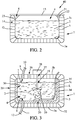
- the container 1 In the non-inflated state, the container 1 is flat, that is to say empty of pressurized inflation gas G. In this non-inflated state, the container 1 occupies a minimal space as represented in Figure 1B , and may for example be folded.
- the container 1 In the inflated state, the container 1 is deployed in volume as represented notably in Figure 1A .
- the container 1 then delimits the internal cavity 4 in order to contain the biopharmaceutical fluid 2.
- the peripheral lateral wall 3c then has, for example, a height H less than 1 metre, even equal to 70 centimetres.
- the bottom wall 3a then has a bottom surface area of less than 1 square metre, even equal to 0.83 square metre.
- the internal cavity 4 has sufficient volume to contain the biopharmaceutical fluid 2.
- the container 1, notably the peripheral lateral wall 3c is rigid or semi-rigid.
- "Rigid or semi-rigid” should be understood to mean that the container 1, notably the peripheral lateral wall 3c, is inflated by the pressurized gas G so as to have at least sufficient rigidity in order to support itself to contain the biopharmaceutical fluid 2.
- the container 1 has, in the inflated state, a peripheral lateral wall 3c that is solid enough to protect the biopharmaceutical fluid 2 with which the internal cavity 4 is filled.
- the wall 3 of the container 1 in the inflated state retains an elastic nature making it possible to ensure a damping function, for example in the event of impacts or turbulences during the operations of transporting the container 1.
- the containers that are already known, and notably those made of stainless steel that are traditionally used do not allow for such damping.
- the capacity for deformation of the inflatable container 1 between the non-inflated state and the inflated state stems firstly from the configuration of the container 1, typically so as to pass from an empty configuration to a volume configuration by virtue of the pressurized inflation gas G.
- This capacity for deformation may stem, secondly, from an intrinsic capacity for deformation of the wall 3 of the container 1, notably of the outer 29 and/or inner 30 portions, by virtue of the fact that they may exhibit a certain capacity for extension, notably elastic.
- the intermediate space 14 of the wall 3 forms and delimits a leak-tight inflation chamber.
- the wall 3 is provided with an injection orifice 15, that is to say a passage for injection of inflation gas G fluidically connected with the inflation chamber.
- An injection tube 16 is associated with the injection orifice 15 of the wall 3, by a leak-tight link having, at the opposite end, an inlet 17 for injection of inflation gas G into the inflation chamber.
- the injection orifice 17 or the injection tube 16 may be sealed, notably irreversibly, for example by welding.
- Leak-tight link should be understood here to mean a structure that is already known such that the wall 3 of the container 1 and the tube 16, fluidically connected with the orifice 15, are associated with one another, so as to both not allow any passage at the link between them for outside air or inflation gas G.
- the container 1 In the inflated state, the container 1 has a capacity of between 100 litres and 1000 litres, in particular between 200 and 500 litres, and it depends on the requirements and the applications.
- the wall 3 may be adapted to come directly into contact with the biopharmaceutical fluid 2.
- the inner portion 30 may be neutral to and/or biocompatible with the biopharmaceutical fluid 2 which fills the container 1. In other words, the quality of the biopharmaceutical fluid 2 is not affected by its coming into contact with the inner portion 30 of the container 1.
- the inner portion 30 may, to this end, be covered with or formed by low-density polyethylene (LDPE).
- LDPE low-density polyethylene
- the container 1 may also comprise an internal pouch 21, adapted to be interposed between the inner portion 30 of the container 1 and the biopharmaceutical fluid 2.
- An internal pouch 21 may notably be used and arranged in the internal cavity 4 of the container 1 when the latter comprises an opening 6 according to the second exemplary embodiment as described previously and as represented in Figure 2 .
- Such an internal pouch 21 is for example described in the patent FR 2781202 .
- the internal pouch 21 may be flexible and leak-tight.
- the internal pouch 21 is formed from a closed wall 22, made of plastic material. "Leak-tight" should be understood here to mean that the wall 22 of the internal pouch 21 does not allow any passage of biopharmaceutical fluid 2, of gas, or of possible contaminants.
- the internal pouch 21 is placed entirely in, that is to say inside of, the internal cavity 4 of the container 1.
- the internal pouch 21 preferably has a form complementing that of the internal cavity 4 of the container 1.
- the internal pouch 21 also has a parallelepipedal form in order to be shaped to and inserted easily in the internal cavity 4.
- the internal pouch 21, once filled with biopharmaceutical fluid shapes itself to the form of the internal cavity 4 because of the pressure exerted by the biopharmaceutical fluid 2 on its wall 22.
- the wall 22 of the internal pouch 21 may be simply positioned in the internal cavity 4 or may be fixed to the wall 3 of the container 1, for example on a common edge or a common lateral surface 23.
- the wall 22 of the internal pouch 21 may be fixed to the container 1 by any means.
- the internal pouch 21 may be fixed to the container 1 reversibly for example using self-gripping means.
- the internal pouch 21 may thus be detached from the container 1, for example once the container 1 has been emptied of the biopharmaceutical fluid 2.
- the internal pouch 21 may then be an element that is distinct and separate from the container 1.
- the invention then also relates to a system 40 comprising a container 1 and an internal pouch 21 distinct from the container 1.
- the internal pouch 21 may be fixed irreversibly, that is to say definitively, to the container 1. According to this variant, the internal pouch 21 may be fixed to the container 1 by gluing, by welding or by any other similar means.
- the internal pouch 21 may be provided with an orifice, that is to say a passage for filling with the biopharmaceutical fluid 2 and an orifice, that is to say a passage for emptying the biopharmaceutical fluid 2.
- a tube for filling the internal pouch 21 is associated with the filling orifice by leak-tight links having, at the opposite end, a filling inlet.
- a draining tube is associated with the draining orifice having, at the opposite end, a draining outlet.
- the internal pouch 21 may comprise a single orifice for filling and for draining.
- a single tube serving as tube for filling and tube for emptying the chamber of biopharmaceutical fluid 2 is then associated by a leak-tight link with the orifice of the internal pouch 21.
- the internal pouch 21 may comprise more than two filling and draining orifices, and therefore more than two filling and/or draining tubes.
- the filling tube and/or the draining tube may be formed in, respectively may pass through, the wall 3 of the container 1.
- the filling tube and/or the draining tube may pass through the opening 6 of the container 1 if appropriate.
- the internal pouch 21 is preferably at least partly, even totally, transparent or translucent so as to make it possible to view through, and in particular through the wall 22, the biopharmaceutical fluid 2. Moreover, the internal pouch 21 may also be at least partly, even totally, opaque to light or to ultraviolet rays for example to guarantee optimal conservation of the biopharmaceutical product 2, notably if the biopharmaceutical product 2 is a photosensitive product.
- the lateral peripheral wall 3c of the container 1 entirely surrounds the internal cavity 4.
- the lateral peripheral wall 3c of the container 1 is advantageously solid, that is to say without any holes or openings, that is to say also completely closed.
- the lateral peripheral wall 3c thus extends along the surface around the internal cavity 4.
- the lateral peripheral wall 3c allows for a better protection of the biopharmaceutical fluid 2 and of the internal pouch 21 if appropriate.
- there is otherwise a risk when the internal pouch 21 is filled with biopharmaceutical fluid 2, of the wall 22 of the internal pouch 21 being deformed at an opening of the lateral peripheral wall 3c, notably by virtue of the pressure of the biopharmaceutical fluid 2.
- This may have the consequence of creating an area of mechanical stress on the wall 22 that may ultimately lead to a degradation, even a tearing, of this wall 22 of the internal pouch 21.
- the container 1 may also comprise heating and/or cooling means intended to heat and/or cool the biopharmaceutical fluid 2 of the container 1.
- the wall 3 of the container 1, notably the inner portion 30, may be made of a material exhibiting a certain thermal conductivity, for example greater than that of stainless steel which is approximately 16 W -1 .m -1 .k -1 at 23 degrees Celsius, so as to improve the implementation of the heating and/or cooling means.
- the intermediate space 14 delimited by the wall 3 may comprise a heating and/or cooling means in the form of a chamber 34 adapted to contain a cooling and/or heating liquid L, as represented in Figure 3 .
- a heating and/or cooling means in the form of a chamber 34 adapted to contain a cooling and/or heating liquid L, as represented in Figure 3 .
- means for controlling the temperature of the biopharmaceutical fluid 2 in the container 1 and means for controlling the heating and/or cooling means.
- Such means for controlling the temperature are borne by one or more ports provided for this purpose.
- the container 1 may comprise mixing means 19.
- the mixing means 19 may for example take the form of one or more shafts fixed to the wall 3 of the container 1, suitable for being rotationally driven by a motor 38 situated outside the container 1 and for rotationally driving at least one mixing member 39.
- a mixing member 39 may for example take the form of a propeller having a hub supporting a number of blades.
- the container comprises an opening 37 in order to connect the shaft 19 to the motor 38.
- the container 1 may also comprise aeration means 20 suitable for delivering to the content a certain quantity of aeration gas.
- aeration means 20 thus make it possible to aerate the biopharmaceutical fluid 2 which is located in the internal cavity 4 of the container 1.
- the aeration means 20 may comprise means 35 for supplying aeration gas having at least one tubular element extending by fluidic connection from the outside of the container 2.
- the supply means 35 are advantageously fixed onto the inner portion 30 of the wall in order not to risk interaction or to be in contact with the mixing means 19 as appropriate.
- aeration gas discharge orifice 36 formed in the top part of the wall 3 of the container 1.
- Such an aeration gas discharge orifice 36 makes it possible to discharge from the container 2, to the outside, the gas which has not been mixed with the content of the container 2.
- sensors of pH, oxygen measurement, conductivity and/or biomass type via a port passing through the wall 3 of the container 1 by leak-tight link.
- at least one sensor passes through the wall 22 of the internal pouch 21 and is placed partially in the internal cavity 4 via such a port.
- the invention relates also to a system 24 for inflating a container 1.
- the system 24 comprises the container 1 and a device 25 for inflating the container 1.
- the inflation device 25 comprises a source 26 of pressurized inflation gas G and a line 27 for injecting pressurized inflation gas G, suitable for being associated by fluidic connection or associated by fluidic connection at the outlet with the injection orifice 15 for pressurized inflation gas G of the container 1.
- the device 25 also comprises a monitoring and control element 28.
- the monitoring and control element 28 may for example be a controller of pressure of the pressurized inflation gas G in the injection line 27, so as to order the injection of inflation gas G when that is desired and order the injection with the desired pressure.
- Such an element 28 may be a pressure gauge, an adjustable valve and/or a control line between them.
- the invention relates also to a method for receiving and transporting biopharmaceutical fluid 2.
- the container 1, notably the inflation chamber, is inflated with the inflation device 25.
- the injection line 27 for pressurized inflation gas G is associated by fluidic connection with the injection inlet 17 for pressurized inflation gas G of the container 1.
- the container 1 is then in the inflated state.
- the container 1 may then be dissociated from the inflation device 25.
- the internal pouch 21 is introduced into the internal cavity 4 of the container 1.
- the internal cavity 4 of the container 1 is filled with biopharmaceutical fluid 2, notably via the filling inlet 10 of the container or the filling inlet of the internal pouch 21, then the filling inlet 10 is brought to the closed state, the draining outlet 12 being also in the closed state.
- the container 1 may be loaded onto a ship, a truck, an aeroplane in order to transport the biopharmaceutical fluid 2.
- the container 1 is emptied of the biopharmaceutical fluid 2 by bringing the draining outlet 12 to the open state.
- the container 1 may thus be emptied of all of the biopharmaceutical fluid 2.
- the internal pouch 21 may be taken out of the container 1 if appropriate.
- the internal pouch 21 may be disposed of, the latter being disposable.
- the container is disposable.
- the container 1 is disposed of after its use, notably after having been emptied of the biopharmaceutical fluid 2.
- the method described above may be carried out partially, the steps described above being able to be carried out independently of one another.
Landscapes
- Life Sciences & Earth Sciences (AREA)
- Engineering & Computer Science (AREA)
- Chemical Kinetics & Catalysis (AREA)
- Chemical & Material Sciences (AREA)
- Health & Medical Sciences (AREA)
- General Health & Medical Sciences (AREA)
- Wood Science & Technology (AREA)
- Dentistry (AREA)
- Zoology (AREA)
- Environmental Sciences (AREA)
- Mechanical Engineering (AREA)
- Public Health (AREA)
- Veterinary Medicine (AREA)
- Animal Behavior & Ethology (AREA)
- Pharmacology & Pharmacy (AREA)
- Aviation & Aerospace Engineering (AREA)
- Packages (AREA)
- Physics & Mathematics (AREA)
- Thermal Sciences (AREA)
Claims (14)
- Conteneur (1) pour transporter un fluide biopharmaceutique (2), le conteneur (1) comprenant une paroi étanche aux fuites (3) ayant une partie externe (29) et une partie interne (30), la partie externe (29) et la partie interne (30) délimitant entre elles un espace intermédiaire (14) qui peut être gonflé sous pression avec un gaz de gonflage (G), l'espace intermédiaire (14) comprenant une pluralité de filaments rigides (33) s'étendant de manière rectiligne entre la partie externe (29) et la partie interne (30) dans l'espace intermédiaire (14) et transversalement par rapport aux parties externe et interne (29, 30), le conteneur (1) étant adapté pour être, de manière alternée, dans :- un état non gonflé dans lequel le conteneur (1) est dépourvu de gaz de gonflage sous pression (G),- un état gonflé dans lequel la paroi (3) du conteneur (1) est gonflée et délimite une cavité interne (4) adaptée pour contenir le fluide biopharmaceutique (2),la paroi (3) comprenant une paroi latérale périphérique (3c) autour de la cavité interne (4), la paroi latérale périphérique (3c) étant complètement rigide ou semi-rigide lorsque le conteneur (1) est à l'état gonflé afin de garantir une protection du fluide biopharmaceutique (2),
la partie externe (29) et/ou la partie interne (30) comprenant une pluralité de couches de matière plastique collées ensemble superposées les unes sur les autres. - Conteneur (1) selon la revendication 1, dans lequel la cavité interne (4) est complètement entourée par la paroi (3) afin de former une cavité interne (4) fermée et stérile.
- Conteneur (1) selon la revendication 1, dans lequel la paroi (3) comprend en outre une paroi supérieure (3b) qui est partiellement ou complètement ouverte afin de former une ouverture (6) émergeant dans la cavité interne (4).
- Conteneur (1) selon l'une quelconque des revendications précédentes, dans lequel la partie interne (30) est compatible avec et/ou neutre par rapport au fluide biopharmaceutique (2), le fluide biopharmaceutique (2) étant directement en contact avec la partie interne (30).
- Conteneur (1) selon l'une des revendications 1 à 3, dans lequel une poche interne (21) réalisée à partir de matière plastique, flexible et étanche aux fuites, est agencée dans la cavité interne (4), la poche interne (21) étant appropriée et prévue pour recevoir le fluide biopharmaceutique (2), dans lequel la poche interne (21) est fixée de manière réversible sur la partie interne (30), la poche interne (21) étant un élément distinct et séparé du conteneur (1).
- Conteneur (1) selon l'une des revendications 1 à 3, dans lequel une poche interne (21) réalisée à partir de matière plastique, flexible et étanche aux fuites, est agencée dans la cavité interne (4), la poche interne (21) étant appropriée et prévue pour recevoir le fluide biopharmaceutique (2), dans lequel la poche interne (21) est fixée, de manière irréversible, sur la partie interne (30) du conteneur (1) par soudage, collage ou similaire.
- Conteneur (1) selon l'une quelconque des revendications précédentes, comprenant au moins un orifice d'injection (15) pour le gaz de gonflage (G) raccordé, de manière fluidique, avec l'espace intermédiaire (14), un tube d'injection (16) étant associé avec l'orifice d'injection (15) par une liaison étanche aux fuites et ayant une entrée d'injection (17) opposée à l'orifice d'injection (15).
- Conteneur (1) selon l'une quelconque des revendications précédentes, dans lequel la cavité interne (4) du conteneur (1) a une capacité comprise entre 100 litres et 1000 litres, même entre 200 litres et 500 litres.
- Conteneur (1) selon l'une quelconque des revendications précédentes, comprenant un moyen pour chauffer et/ou refroidir (34) le fluide biopharmaceutique (2) destiné à être contenu par le conteneur (1), dans lequel de préférence l'espace intermédiaire (14) comprend une chambre (34) adaptée pour contenir un liquide de refroidissement et/ou de chauffage (L) permettant de chauffer et/ou de refroidir le fluide biopharmaceutique (2).
- Conteneur (1) selon l'une quelconque des revendications précédentes, comprenant un moyen pour mélanger (19) et/ou un moyen pour aérer (20) le fluide biopharmaceutique (2) qui sont fixés sur la paroi (3) du conteneur (1).
- Conteneur (1) selon l'une quelconque des revendications précédentes, dans lequel le conteneur comprend une paroi inférieure (3a) reliée à la paroi périphérique latérale (3c), la paroi périphérique latérale (3c) étant agencée verticalement et transversalement à la paroi inférieure (3a) de sorte que le conteneur (1), à l'état gonflé, se présente sous la forme d'un réservoir.
- Système (40) comprenant un conteneur (1) selon l'une quelconque des revendications précédentes et une poche interne (21) réalisée à partir de matière plastique, flexible et étanche aux fuites, adaptée pour être agencée dans la cavité interne (4) du conteneur (1), la poche interne (21) étant appropriée et prévue pour recevoir le fluide biopharmaceutique (2) .
- Système (24) pour gonfler un conteneur (1) selon l'une quelconque des revendications 1 à 11, le système (24) comprenant le récipient (1) et un dispositif (25) pour gonfler le conteneur (1), le dispositif de gonflage (25) comprenant une source (26) de gaz de gonflage sous pression (G) et une ligne d'injection (27) pour le gaz de gonflage sous pression (G), appropriée pour être associée, par raccordement fluidique, au niveau de la sortie, à un orifice d'injection (15) du conteneur (1).
- Procédé pour recevoir et transporter du fluide biopharmaceutique (2), dans lequel :- un système (24) selon la revendication 13, est prévu pour gonfler un conteneur (1) selon l'une quelconque des revendications 1 à 11, le conteneur (1) étant initialement à l'état non gonflé,- l'espace intermédiaire (14) de la paroi (3) du conteneur (2) est gonflé avec le dispositif de gonflage (25),- la cavité interne (4) du conteneur (1) est remplie avec le fluide biopharmaceutique (2) à un emplacement de remplissage, notamment via une entrée de remplissage (10),- le conteneur (1) est transporté de l'emplacement de remplissage à un emplacement d'utilisation du fluide biopharmaceutique (2),- à l'emplacement d'utilisation, le conteneur (1) est vidé du fluide biopharmaceutique (2) via une sortie de drainage (12),- le conteneur (1) est jeté, le conteneur (1) étant jetable.
Priority Applications (3)
| Application Number | Priority Date | Filing Date | Title |
|---|---|---|---|
| EP15306951.3A EP3178754B1 (fr) | 2015-12-07 | 2015-12-07 | Conteneur gonflable de transport d'un fluide biopharmaceutique et système et procédé mettant en oeuvre un tel conteneur |
| PCT/EP2016/079974 WO2017097793A1 (fr) | 2015-12-07 | 2016-12-07 | Contenant gonflable servant à transporter un fluide biopharmaceutique et système et procédé associés à un tel contenant |
| US16/060,131 US11008148B2 (en) | 2015-12-07 | 2016-12-07 | Inflatable container for transporting a biopharmaceutical fluid and system and method implementing such a container |
Applications Claiming Priority (1)
| Application Number | Priority Date | Filing Date | Title |
|---|---|---|---|
| EP15306951.3A EP3178754B1 (fr) | 2015-12-07 | 2015-12-07 | Conteneur gonflable de transport d'un fluide biopharmaceutique et système et procédé mettant en oeuvre un tel conteneur |
Publications (2)
| Publication Number | Publication Date |
|---|---|
| EP3178754A1 EP3178754A1 (fr) | 2017-06-14 |
| EP3178754B1 true EP3178754B1 (fr) | 2021-06-23 |
Family
ID=55027651
Family Applications (1)
| Application Number | Title | Priority Date | Filing Date |
|---|---|---|---|
| EP15306951.3A Active EP3178754B1 (fr) | 2015-12-07 | 2015-12-07 | Conteneur gonflable de transport d'un fluide biopharmaceutique et système et procédé mettant en oeuvre un tel conteneur |
Country Status (3)
| Country | Link |
|---|---|
| US (1) | US11008148B2 (fr) |
| EP (1) | EP3178754B1 (fr) |
| WO (1) | WO2017097793A1 (fr) |
Families Citing this family (1)
| Publication number | Priority date | Publication date | Assignee | Title |
|---|---|---|---|---|
| US11590055B2 (en) * | 2020-07-30 | 2023-02-28 | Sartorius Stedim North America | Storage/containment unit for flexible pouch filled with biopharmaceutical fluid, and method of assembling a freeze/thaw containment system, using a protecting body |
Citations (3)
| Publication number | Priority date | Publication date | Assignee | Title |
|---|---|---|---|---|
| US3044515A (en) * | 1959-04-27 | 1962-07-17 | Phillips Petroleum Co | Self-erecting collapsible containers |
| EP2921739A1 (fr) * | 2014-03-20 | 2015-09-23 | Air- Bag Packing Co., Ltd. | Gaine d'air antivibration à structure de fermeture d'extrémité améliorée |
| US20170217660A1 (en) * | 2014-09-29 | 2017-08-03 | Shanghai Air-Paq Composite Material Co., Ltd. | Multilayer Air Packaging Device and Staggered Laminated Air Packaging Device |
Family Cites Families (41)
| Publication number | Priority date | Publication date | Assignee | Title |
|---|---|---|---|---|
| US2751953A (en) * | 1953-10-01 | 1956-06-26 | Bruce F Grimm | Collapsible container |
| US3205106A (en) * | 1964-07-16 | 1965-09-07 | Goodyear Aerospace Corp | Method of increasing stiffness of an inflated structure |
| NL6816724A (fr) * | 1968-02-22 | 1969-08-26 | ||
| US3556186A (en) * | 1968-10-18 | 1971-01-19 | Gerard Besthorne | Inflatable bag |
| US3616126A (en) * | 1968-11-01 | 1971-10-26 | Minnesota Mining & Mfg | Compression energy absorbing structure |
| US3742994A (en) * | 1971-10-21 | 1973-07-03 | Colgate Palmolive Co | Inflatable container |
| US3838794A (en) * | 1972-07-10 | 1974-10-01 | H Markham | Package for storing and dispensing liquids |
| US4048994A (en) * | 1976-08-24 | 1977-09-20 | Lo Liu Ying P | Self-inflating liquid container for keeping I.V. fluid or blood plasma |
| EP0077189B1 (fr) * | 1981-10-09 | 1987-08-12 | Biofusion (Proprietary) Limited | Unité de perfusion |
| US4462331A (en) * | 1983-01-31 | 1984-07-31 | The United States Of America As Represented By The Secretary Of The Navy | Inflatable bottom construction for inflatable boat |
| US4675930A (en) * | 1987-05-21 | 1987-06-30 | Theracom Corporation | Support cushion |
| US4906502A (en) * | 1988-02-05 | 1990-03-06 | Robert C. Bogert | Pressurizable envelope and method |
| WO1989010315A1 (fr) * | 1988-04-30 | 1989-11-02 | Korfmacher Trading Gmbh | Tapis de stockage ou de support, notamment pour des applications d'emballage |
| FR2653098B1 (fr) * | 1989-10-16 | 1992-04-24 | Lepinoy Ind | Dispositif du type comportant une coque rigide enveloppante, delimitant un volume interne et au moins une chambre etanche occupant ledit volume interne. |
| US5152018A (en) * | 1989-12-15 | 1992-10-06 | Cascade Designs, Inc. | Batting filled self inflatable body |
| JPH04215927A (ja) * | 1990-05-04 | 1992-08-06 | Puff Pac Ind Inc | パッケージシステム |
| US5624035A (en) * | 1995-06-07 | 1997-04-29 | Inno Design, Inc. | Carrying case with inflatable sections |
| EP0755775B1 (fr) * | 1995-07-27 | 2001-06-13 | Zodiac International | Panneau sensiblement rigide thermiquement isolant et procédé pour sa fabrication |
| US5720728A (en) * | 1996-03-25 | 1998-02-24 | Mallinckrodt Medical, Inc. | Teardrop shaped pressurizing apparatus |
| FR2760717B1 (fr) * | 1997-03-17 | 2001-02-16 | Zodiac Int | Plancher gonflable, notamment pour embarcation gonflable |
| US5897012A (en) | 1997-04-04 | 1999-04-27 | Sortwell & Co. | Collapsible intermediate bulk container |
| US5833053A (en) * | 1997-04-04 | 1998-11-10 | Wood; James | Inflatable eyeglass case |
| US5941866A (en) * | 1997-07-25 | 1999-08-24 | Bracco Research Usa | Means to maintain configuration of flexible medical container |
| FR2781202B1 (fr) | 1998-07-16 | 2001-01-12 | Stedim Sa | Poches pour produits fluides bio-pharmaceutiques |
| DE19848533A1 (de) * | 1998-10-21 | 2000-04-27 | Ludger Sproll | Verpackungsbehälter |
| US6283296B1 (en) * | 1998-12-29 | 2001-09-04 | Air Packaging Technologies, Inc. | Quilted inflatable packaging device |
| KR20000059492A (ko) * | 1999-03-04 | 2000-10-05 | 채정수 | 침구용 매트리스, 그의 제조방법 및 제조장치 |
| US6176613B1 (en) * | 2000-05-04 | 2001-01-23 | Tzan-Kuo Chen | Packing bag with air cushion |
| US6460837B1 (en) * | 2000-12-04 | 2002-10-08 | Edward J. Ahern | Filament based energy absorbing system |
| US20030155268A1 (en) * | 2002-02-21 | 2003-08-21 | Lo-Pin Wang | Shock-absorbing bag |
| DE602004004051T2 (de) | 2003-09-04 | 2007-08-16 | Millipore Corp., Billerica | Stützsystem für beutel |
| US20050061409A1 (en) * | 2003-09-24 | 2005-03-24 | Ip Sing Chung | Carry bag having inflatable protective wall |
| US20090266722A1 (en) * | 2008-04-23 | 2009-10-29 | Eggs Overnight, Inc. | Reusable shipping container and systems thereof |
| US20080035519A1 (en) * | 2004-11-24 | 2008-02-14 | Swartz John R | Carry Device |
| JP2008539146A (ja) * | 2005-04-25 | 2008-11-13 | アドバンスド テクノロジー マテリアルズ,インコーポレイテッド | 化学試薬及び組成を保存・分配する装置及びプロセス |
| US8608191B2 (en) * | 2008-12-09 | 2013-12-17 | Dainese S.P.A. | Protection device including an inflatable member |
| US20100303387A1 (en) | 2009-05-29 | 2010-12-02 | Peter Dahlquist | Inflatable shipping container |
| US8636453B2 (en) | 2011-04-19 | 2014-01-28 | Meissner Filtration Products, Inc. | Inflatable dunnage |
| US20130092706A1 (en) | 2011-10-14 | 2013-04-18 | Grayling Industries, Inc | Pressurized liner |
| FR3003245B1 (fr) * | 2013-03-13 | 2015-03-20 | Sartorius Stedim Biotech | Reception, vidage et transfert sous pression d'une grande quantite de fluide biopharmaceutique en vue d'un traitement ulterieur. |
| CN107548285A (zh) * | 2015-03-11 | 2018-01-05 | 斯韦尔工业有限责任公司 | 漏针充气冷却器 |
-
2015
- 2015-12-07 EP EP15306951.3A patent/EP3178754B1/fr active Active
-
2016
- 2016-12-07 WO PCT/EP2016/079974 patent/WO2017097793A1/fr not_active Ceased
- 2016-12-07 US US16/060,131 patent/US11008148B2/en active Active
Patent Citations (3)
| Publication number | Priority date | Publication date | Assignee | Title |
|---|---|---|---|---|
| US3044515A (en) * | 1959-04-27 | 1962-07-17 | Phillips Petroleum Co | Self-erecting collapsible containers |
| EP2921739A1 (fr) * | 2014-03-20 | 2015-09-23 | Air- Bag Packing Co., Ltd. | Gaine d'air antivibration à structure de fermeture d'extrémité améliorée |
| US20170217660A1 (en) * | 2014-09-29 | 2017-08-03 | Shanghai Air-Paq Composite Material Co., Ltd. | Multilayer Air Packaging Device and Staggered Laminated Air Packaging Device |
Also Published As
| Publication number | Publication date |
|---|---|
| US11008148B2 (en) | 2021-05-18 |
| EP3178754A1 (fr) | 2017-06-14 |
| WO2017097793A1 (fr) | 2017-06-15 |
| US20180354700A1 (en) | 2018-12-13 |
Similar Documents
| Publication | Publication Date | Title |
|---|---|---|
| US10935298B2 (en) | Cryogenic container | |
| JP6122444B2 (ja) | ライナベースの搬出および分配システム | |
| US10532870B2 (en) | Device for conveying a bag comprising a biopharmaceutical fluid and systems and a method using same | |
| JP6877809B2 (ja) | 使い捨て容器、混合システム、および梱包 | |
| EP2516117B1 (fr) | Chaîne de fabrication jetable | |
| US20110151551A1 (en) | Bioreactors | |
| US20230313101A1 (en) | Disposable cell culture bag | |
| US12071282B2 (en) | System and method for packaging a bioprocessing bag and associated components, and packaging for a bioprocessing bag | |
| US20190307642A1 (en) | Pouch comprising a shape memory material to contain a biopharmaceutical fluid | |
| US20120199614A1 (en) | Systems and methods for use in storing biopharmaceutical materials | |
| US6543495B2 (en) | Multiple access container and methods for the transfer of fluent materials | |
| US11008148B2 (en) | Inflatable container for transporting a biopharmaceutical fluid and system and method implementing such a container | |
| CN107848687B (zh) | 用于存储、运输和/或处理生物液体的装置及处理经消毒或无菌液体的方法 | |
| EP3081286B1 (fr) | Système de conteneur et tube pour bioprocédé et méthode d'utilisation | |
| US11925599B2 (en) | Container for transporting a biopharmaceutical fluid comprising a shape memory material | |
| US12305152B2 (en) | Disposable containers and reaction systems | |
| WO2025230631A1 (fr) | Récipient de biotraitement flexible | |
| HK1162120B (en) | Cryogenic container |
Legal Events
| Date | Code | Title | Description |
|---|---|---|---|
| PUAI | Public reference made under article 153(3) epc to a published international application that has entered the european phase |
Free format text: ORIGINAL CODE: 0009012 |
|
| STAA | Information on the status of an ep patent application or granted ep patent |
Free format text: STATUS: THE APPLICATION HAS BEEN PUBLISHED |
|
| AK | Designated contracting states |
Kind code of ref document: A1 Designated state(s): AL AT BE BG CH CY CZ DE DK EE ES FI FR GB GR HR HU IE IS IT LI LT LU LV MC MK MT NL NO PL PT RO RS SE SI SK SM TR |
|
| AX | Request for extension of the european patent |
Extension state: BA ME |
|
| STAA | Information on the status of an ep patent application or granted ep patent |
Free format text: STATUS: REQUEST FOR EXAMINATION WAS MADE |
|
| 17P | Request for examination filed |
Effective date: 20171206 |
|
| RBV | Designated contracting states (corrected) |
Designated state(s): AL AT BE BG CH CY CZ DE DK EE ES FI FR GB GR HR HU IE IS IT LI LT LU LV MC MK MT NL NO PL PT RO RS SE SI SK SM TR |
|
| STAA | Information on the status of an ep patent application or granted ep patent |
Free format text: STATUS: EXAMINATION IS IN PROGRESS |
|
| 17Q | First examination report despatched |
Effective date: 20180405 |
|
| GRAP | Despatch of communication of intention to grant a patent |
Free format text: ORIGINAL CODE: EPIDOSNIGR1 |
|
| STAA | Information on the status of an ep patent application or granted ep patent |
Free format text: STATUS: GRANT OF PATENT IS INTENDED |
|
| INTG | Intention to grant announced |
Effective date: 20210310 |
|
| GRAS | Grant fee paid |
Free format text: ORIGINAL CODE: EPIDOSNIGR3 |
|
| GRAA | (expected) grant |
Free format text: ORIGINAL CODE: 0009210 |
|
| STAA | Information on the status of an ep patent application or granted ep patent |
Free format text: STATUS: THE PATENT HAS BEEN GRANTED |
|
| AK | Designated contracting states |
Kind code of ref document: B1 Designated state(s): AL AT BE BG CH CY CZ DE DK EE ES FI FR GB GR HR HU IE IS IT LI LT LU LV MC MK MT NL NO PL PT RO RS SE SI SK SM TR |
|
| REG | Reference to a national code |
Ref country code: GB Ref legal event code: FG4D |
|
| REG | Reference to a national code |
Ref country code: CH Ref legal event code: EP |
|
| REG | Reference to a national code |
Ref country code: DE Ref legal event code: R096 Ref document number: 602015070612 Country of ref document: DE Ref country code: AT Ref legal event code: REF Ref document number: 1404139 Country of ref document: AT Kind code of ref document: T Effective date: 20210715 |
|
| REG | Reference to a national code |
Ref country code: IE Ref legal event code: FG4D |
|
| REG | Reference to a national code |
Ref country code: LT Ref legal event code: MG9D |
|
| PG25 | Lapsed in a contracting state [announced via postgrant information from national office to epo] |
Ref country code: FI Free format text: LAPSE BECAUSE OF FAILURE TO SUBMIT A TRANSLATION OF THE DESCRIPTION OR TO PAY THE FEE WITHIN THE PRESCRIBED TIME-LIMIT Effective date: 20210623 Ref country code: LT Free format text: LAPSE BECAUSE OF FAILURE TO SUBMIT A TRANSLATION OF THE DESCRIPTION OR TO PAY THE FEE WITHIN THE PRESCRIBED TIME-LIMIT Effective date: 20210623 Ref country code: BG Free format text: LAPSE BECAUSE OF FAILURE TO SUBMIT A TRANSLATION OF THE DESCRIPTION OR TO PAY THE FEE WITHIN THE PRESCRIBED TIME-LIMIT Effective date: 20210923 Ref country code: HR Free format text: LAPSE BECAUSE OF FAILURE TO SUBMIT A TRANSLATION OF THE DESCRIPTION OR TO PAY THE FEE WITHIN THE PRESCRIBED TIME-LIMIT Effective date: 20210623 |
|
| REG | Reference to a national code |
Ref country code: AT Ref legal event code: MK05 Ref document number: 1404139 Country of ref document: AT Kind code of ref document: T Effective date: 20210623 |
|
| PG25 | Lapsed in a contracting state [announced via postgrant information from national office to epo] |
Ref country code: LV Free format text: LAPSE BECAUSE OF FAILURE TO SUBMIT A TRANSLATION OF THE DESCRIPTION OR TO PAY THE FEE WITHIN THE PRESCRIBED TIME-LIMIT Effective date: 20210623 Ref country code: GR Free format text: LAPSE BECAUSE OF FAILURE TO SUBMIT A TRANSLATION OF THE DESCRIPTION OR TO PAY THE FEE WITHIN THE PRESCRIBED TIME-LIMIT Effective date: 20210924 Ref country code: RS Free format text: LAPSE BECAUSE OF FAILURE TO SUBMIT A TRANSLATION OF THE DESCRIPTION OR TO PAY THE FEE WITHIN THE PRESCRIBED TIME-LIMIT Effective date: 20210623 Ref country code: SE Free format text: LAPSE BECAUSE OF FAILURE TO SUBMIT A TRANSLATION OF THE DESCRIPTION OR TO PAY THE FEE WITHIN THE PRESCRIBED TIME-LIMIT Effective date: 20210623 Ref country code: NO Free format text: LAPSE BECAUSE OF FAILURE TO SUBMIT A TRANSLATION OF THE DESCRIPTION OR TO PAY THE FEE WITHIN THE PRESCRIBED TIME-LIMIT Effective date: 20210923 |
|
| REG | Reference to a national code |
Ref country code: NL Ref legal event code: MP Effective date: 20210623 |
|
| PG25 | Lapsed in a contracting state [announced via postgrant information from national office to epo] |
Ref country code: SK Free format text: LAPSE BECAUSE OF FAILURE TO SUBMIT A TRANSLATION OF THE DESCRIPTION OR TO PAY THE FEE WITHIN THE PRESCRIBED TIME-LIMIT Effective date: 20210623 Ref country code: SM Free format text: LAPSE BECAUSE OF FAILURE TO SUBMIT A TRANSLATION OF THE DESCRIPTION OR TO PAY THE FEE WITHIN THE PRESCRIBED TIME-LIMIT Effective date: 20210623 Ref country code: CZ Free format text: LAPSE BECAUSE OF FAILURE TO SUBMIT A TRANSLATION OF THE DESCRIPTION OR TO PAY THE FEE WITHIN THE PRESCRIBED TIME-LIMIT Effective date: 20210623 Ref country code: EE Free format text: LAPSE BECAUSE OF FAILURE TO SUBMIT A TRANSLATION OF THE DESCRIPTION OR TO PAY THE FEE WITHIN THE PRESCRIBED TIME-LIMIT Effective date: 20210623 Ref country code: AT Free format text: LAPSE BECAUSE OF FAILURE TO SUBMIT A TRANSLATION OF THE DESCRIPTION OR TO PAY THE FEE WITHIN THE PRESCRIBED TIME-LIMIT Effective date: 20210623 Ref country code: ES Free format text: LAPSE BECAUSE OF FAILURE TO SUBMIT A TRANSLATION OF THE DESCRIPTION OR TO PAY THE FEE WITHIN THE PRESCRIBED TIME-LIMIT Effective date: 20210623 Ref country code: RO Free format text: LAPSE BECAUSE OF FAILURE TO SUBMIT A TRANSLATION OF THE DESCRIPTION OR TO PAY THE FEE WITHIN THE PRESCRIBED TIME-LIMIT Effective date: 20210623 Ref country code: PT Free format text: LAPSE BECAUSE OF FAILURE TO SUBMIT A TRANSLATION OF THE DESCRIPTION OR TO PAY THE FEE WITHIN THE PRESCRIBED TIME-LIMIT Effective date: 20211025 Ref country code: NL Free format text: LAPSE BECAUSE OF FAILURE TO SUBMIT A TRANSLATION OF THE DESCRIPTION OR TO PAY THE FEE WITHIN THE PRESCRIBED TIME-LIMIT Effective date: 20210623 |
|
| PG25 | Lapsed in a contracting state [announced via postgrant information from national office to epo] |
Ref country code: PL Free format text: LAPSE BECAUSE OF FAILURE TO SUBMIT A TRANSLATION OF THE DESCRIPTION OR TO PAY THE FEE WITHIN THE PRESCRIBED TIME-LIMIT Effective date: 20210623 |
|
| REG | Reference to a national code |
Ref country code: DE Ref legal event code: R097 Ref document number: 602015070612 Country of ref document: DE |
|
| PG25 | Lapsed in a contracting state [announced via postgrant information from national office to epo] |
Ref country code: DK Free format text: LAPSE BECAUSE OF FAILURE TO SUBMIT A TRANSLATION OF THE DESCRIPTION OR TO PAY THE FEE WITHIN THE PRESCRIBED TIME-LIMIT Effective date: 20210623 |
|
| PLBE | No opposition filed within time limit |
Free format text: ORIGINAL CODE: 0009261 |
|
| STAA | Information on the status of an ep patent application or granted ep patent |
Free format text: STATUS: NO OPPOSITION FILED WITHIN TIME LIMIT |
|
| 26N | No opposition filed |
Effective date: 20220324 |
|
| PG25 | Lapsed in a contracting state [announced via postgrant information from national office to epo] |
Ref country code: AL Free format text: LAPSE BECAUSE OF FAILURE TO SUBMIT A TRANSLATION OF THE DESCRIPTION OR TO PAY THE FEE WITHIN THE PRESCRIBED TIME-LIMIT Effective date: 20210623 |
|
| PG25 | Lapsed in a contracting state [announced via postgrant information from national office to epo] |
Ref country code: MC Free format text: LAPSE BECAUSE OF FAILURE TO SUBMIT A TRANSLATION OF THE DESCRIPTION OR TO PAY THE FEE WITHIN THE PRESCRIBED TIME-LIMIT Effective date: 20210623 Ref country code: IT Free format text: LAPSE BECAUSE OF FAILURE TO SUBMIT A TRANSLATION OF THE DESCRIPTION OR TO PAY THE FEE WITHIN THE PRESCRIBED TIME-LIMIT Effective date: 20210623 |
|
| REG | Reference to a national code |
Ref country code: CH Ref legal event code: PL |
|
| GBPC | Gb: european patent ceased through non-payment of renewal fee |
Effective date: 20211207 |
|
| REG | Reference to a national code |
Ref country code: BE Ref legal event code: MM Effective date: 20211231 |
|
| PG25 | Lapsed in a contracting state [announced via postgrant information from national office to epo] |
Ref country code: LU Free format text: LAPSE BECAUSE OF NON-PAYMENT OF DUE FEES Effective date: 20211207 Ref country code: IE Free format text: LAPSE BECAUSE OF NON-PAYMENT OF DUE FEES Effective date: 20211207 Ref country code: GB Free format text: LAPSE BECAUSE OF NON-PAYMENT OF DUE FEES Effective date: 20211207 |
|
| PG25 | Lapsed in a contracting state [announced via postgrant information from national office to epo] |
Ref country code: BE Free format text: LAPSE BECAUSE OF NON-PAYMENT OF DUE FEES Effective date: 20211231 |
|
| PG25 | Lapsed in a contracting state [announced via postgrant information from national office to epo] |
Ref country code: LI Free format text: LAPSE BECAUSE OF NON-PAYMENT OF DUE FEES Effective date: 20211231 Ref country code: CH Free format text: LAPSE BECAUSE OF NON-PAYMENT OF DUE FEES Effective date: 20211231 |
|
| PG25 | Lapsed in a contracting state [announced via postgrant information from national office to epo] |
Ref country code: HU Free format text: LAPSE BECAUSE OF FAILURE TO SUBMIT A TRANSLATION OF THE DESCRIPTION OR TO PAY THE FEE WITHIN THE PRESCRIBED TIME-LIMIT; INVALID AB INITIO Effective date: 20151207 |
|
| PG25 | Lapsed in a contracting state [announced via postgrant information from national office to epo] |
Ref country code: CY Free format text: LAPSE BECAUSE OF FAILURE TO SUBMIT A TRANSLATION OF THE DESCRIPTION OR TO PAY THE FEE WITHIN THE PRESCRIBED TIME-LIMIT Effective date: 20210623 |
|
| P01 | Opt-out of the competence of the unified patent court (upc) registered |
Effective date: 20230526 |
|
| PG25 | Lapsed in a contracting state [announced via postgrant information from national office to epo] |
Ref country code: MK Free format text: LAPSE BECAUSE OF FAILURE TO SUBMIT A TRANSLATION OF THE DESCRIPTION OR TO PAY THE FEE WITHIN THE PRESCRIBED TIME-LIMIT Effective date: 20210623 |
|
| PG25 | Lapsed in a contracting state [announced via postgrant information from national office to epo] |
Ref country code: TR Free format text: LAPSE BECAUSE OF FAILURE TO SUBMIT A TRANSLATION OF THE DESCRIPTION OR TO PAY THE FEE WITHIN THE PRESCRIBED TIME-LIMIT Effective date: 20210623 |
|
| PG25 | Lapsed in a contracting state [announced via postgrant information from national office to epo] |
Ref country code: MT Free format text: LAPSE BECAUSE OF FAILURE TO SUBMIT A TRANSLATION OF THE DESCRIPTION OR TO PAY THE FEE WITHIN THE PRESCRIBED TIME-LIMIT Effective date: 20210623 |
|
| REG | Reference to a national code |
Ref country code: DE Ref legal event code: R081 Ref document number: 602015070612 Country of ref document: DE Owner name: SARTORIUS STEDIM FMT, FR Free format text: FORMER OWNER: SARTORIUS STEDIM FMT SAS, AUBAGNE, FR Ref country code: DE Ref legal event code: R081 Ref document number: 602015070612 Country of ref document: DE Owner name: SARTORIUS STEDIM, FR Free format text: FORMER OWNER: SARTORIUS STEDIM FMT SAS, AUBAGNE, FR |
|
| REG | Reference to a national code |
Ref country code: DE Ref legal event code: R081 Ref document number: 602015070612 Country of ref document: DE Owner name: SARTORIUS STEDIM FMT, FR Free format text: FORMER OWNER: SARTORIUS STEDIM, AUBAGNE, FR |
|
| PGFP | Annual fee paid to national office [announced via postgrant information from national office to epo] |
Ref country code: FR Payment date: 20251218 Year of fee payment: 11 |
|
| PGFP | Annual fee paid to national office [announced via postgrant information from national office to epo] |
Ref country code: DE Payment date: 20251222 Year of fee payment: 11 |