EP3179955B1 - Commande robotisée de préhension à avantage mécanique - Google Patents
Commande robotisée de préhension à avantage mécanique Download PDFInfo
- Publication number
- EP3179955B1 EP3179955B1 EP15831995.4A EP15831995A EP3179955B1 EP 3179955 B1 EP3179955 B1 EP 3179955B1 EP 15831995 A EP15831995 A EP 15831995A EP 3179955 B1 EP3179955 B1 EP 3179955B1
- Authority
- EP
- European Patent Office
- Prior art keywords
- pair
- jaw
- end effector
- jaw members
- support shaft
- Prior art date
- Legal status (The legal status is an assumption and is not a legal conclusion. Google has not performed a legal analysis and makes no representation as to the accuracy of the status listed.)
- Active
Links
Images





Classifications
-
- A—HUMAN NECESSITIES
- A61—MEDICAL OR VETERINARY SCIENCE; HYGIENE
- A61B—DIAGNOSIS; SURGERY; IDENTIFICATION
- A61B17/00—Surgical instruments, devices or methods
- A61B17/28—Surgical forceps
- A61B17/29—Forceps for use in minimally invasive surgery
-
- A—HUMAN NECESSITIES
- A61—MEDICAL OR VETERINARY SCIENCE; HYGIENE
- A61B—DIAGNOSIS; SURGERY; IDENTIFICATION
- A61B34/00—Computer-aided surgery; Manipulators or robots specially adapted for use in surgery
- A61B34/70—Manipulators specially adapted for use in surgery
- A61B34/71—Manipulators operated by drive cable mechanisms
-
- A—HUMAN NECESSITIES
- A61—MEDICAL OR VETERINARY SCIENCE; HYGIENE
- A61B—DIAGNOSIS; SURGERY; IDENTIFICATION
- A61B34/00—Computer-aided surgery; Manipulators or robots specially adapted for use in surgery
- A61B34/30—Surgical robots
-
- A—HUMAN NECESSITIES
- A61—MEDICAL OR VETERINARY SCIENCE; HYGIENE
- A61B—DIAGNOSIS; SURGERY; IDENTIFICATION
- A61B34/00—Computer-aided surgery; Manipulators or robots specially adapted for use in surgery
- A61B34/30—Surgical robots
- A61B34/35—Surgical robots for telesurgery
-
- A—HUMAN NECESSITIES
- A61—MEDICAL OR VETERINARY SCIENCE; HYGIENE
- A61B—DIAGNOSIS; SURGERY; IDENTIFICATION
- A61B34/00—Computer-aided surgery; Manipulators or robots specially adapted for use in surgery
- A61B34/70—Manipulators specially adapted for use in surgery
- A61B34/74—Manipulators with manual electric input means
-
- A—HUMAN NECESSITIES
- A61—MEDICAL OR VETERINARY SCIENCE; HYGIENE
- A61B—DIAGNOSIS; SURGERY; IDENTIFICATION
- A61B90/00—Instruments, implements or accessories specially adapted for surgery or diagnosis and not covered by any of the groups A61B1/00 - A61B50/00, e.g. for luxation treatment or for protecting wound edges
- A61B90/36—Image-producing devices or illumination devices not otherwise provided for
- A61B90/37—Surgical systems with images on a monitor during operation
-
- A—HUMAN NECESSITIES
- A61—MEDICAL OR VETERINARY SCIENCE; HYGIENE
- A61B—DIAGNOSIS; SURGERY; IDENTIFICATION
- A61B17/00—Surgical instruments, devices or methods
- A61B2017/00367—Details of actuation of instruments, e.g. relations between pushing buttons, or the like, and activation of the tool, working tip, or the like
- A61B2017/00398—Details of actuation of instruments, e.g. relations between pushing buttons, or the like, and activation of the tool, working tip, or the like using powered actuators, e.g. stepper motors, solenoids
-
- A—HUMAN NECESSITIES
- A61—MEDICAL OR VETERINARY SCIENCE; HYGIENE
- A61B—DIAGNOSIS; SURGERY; IDENTIFICATION
- A61B17/00—Surgical instruments, devices or methods
- A61B17/28—Surgical forceps
- A61B17/29—Forceps for use in minimally invasive surgery
- A61B2017/2926—Details of heads or jaws
- A61B2017/2927—Details of heads or jaws the angular position of the head being adjustable with respect to the shaft
-
- A—HUMAN NECESSITIES
- A61—MEDICAL OR VETERINARY SCIENCE; HYGIENE
- A61B—DIAGNOSIS; SURGERY; IDENTIFICATION
- A61B17/00—Surgical instruments, devices or methods
- A61B17/28—Surgical forceps
- A61B17/29—Forceps for use in minimally invasive surgery
- A61B2017/2926—Details of heads or jaws
- A61B2017/2932—Transmission of forces to jaw members
- A61B2017/2933—Transmission of forces to jaw members camming or guiding means
- A61B2017/2936—Pins in guiding slots
-
- A—HUMAN NECESSITIES
- A61—MEDICAL OR VETERINARY SCIENCE; HYGIENE
- A61B—DIAGNOSIS; SURGERY; IDENTIFICATION
- A61B17/00—Surgical instruments, devices or methods
- A61B17/28—Surgical forceps
- A61B17/29—Forceps for use in minimally invasive surgery
- A61B2017/2926—Details of heads or jaws
- A61B2017/2932—Transmission of forces to jaw members
- A61B2017/2938—Independently actuatable jaw members, e.g. two actuating rods
-
- A—HUMAN NECESSITIES
- A61—MEDICAL OR VETERINARY SCIENCE; HYGIENE
- A61B—DIAGNOSIS; SURGERY; IDENTIFICATION
- A61B17/00—Surgical instruments, devices or methods
- A61B17/28—Surgical forceps
- A61B17/29—Forceps for use in minimally invasive surgery
- A61B2017/2926—Details of heads or jaws
- A61B2017/2932—Transmission of forces to jaw members
- A61B2017/2939—Details of linkages or pivot points
-
- A—HUMAN NECESSITIES
- A61—MEDICAL OR VETERINARY SCIENCE; HYGIENE
- A61B—DIAGNOSIS; SURGERY; IDENTIFICATION
- A61B34/00—Computer-aided surgery; Manipulators or robots specially adapted for use in surgery
- A61B34/30—Surgical robots
- A61B2034/305—Details of wrist mechanisms at distal ends of robotic arms
Definitions
- the present disclosure relates to robotics, and more specifically to robotic surgical devices and/or systems for performing surgical procedures.
- Robotic surgical systems have been used in minimally invasive medical procedures.
- Some robotic surgical systems included a console supporting a robot arm, and at least one end effector such as a forceps or a grasping tool that was mounted to the robot arm.
- the end effector was inserted into a small incision (via a cannula) or a natural orifice of a patient to position the end effector at a work site within the body of the patient.
- Cables extended from the robot console, through the robot arm, and connected to wrist and/or jaw assemblies of the end effector.
- the cables were actuated by motors that were controlled by a processing system with a user interface for a surgeon or clinician to be able to control the robotic surgical system including the robot arm, the wrist assembly and/or the jaw assembly.
- the wrist assembly had multiple degrees of freedom for movement of the jaw assembly using several cables.
- the wrist assembly provided the freedom for movement by allowing changes to pitch, yaw, or an opening and closing of the jaw assembly.
- end effectors such as grasping and cutting end effectors having smaller cross-sectional areas. These smaller cross-sectional areas reduced the total force that could be applied between the jaws of the end effector. Additionally, designing end effectors supporting multiple degrees of motion required several cables. Each additional cable that was needed further limited the ability to reduce the cross sectional areas of these end effectors.
- US 6,394,998 B1 provides surgical tools or instruments for use in minimally invasive telesurgical applications.
- the instruments typically include a base whereby the instrument is removably mountable on a robotically controlled articulated arm.
- An elongate shaft extends from the base.
- a working end of the shaft is disposed at an end of the shaft remote from the base.
- a wrist member is pivotally mounted on the working end.
- At least one end effector element mounting formation is pivotally mounted on an opposed end of the wrist member.
- a plurality of elongate elements, e.g., cables, extend from the end effector element mounting formation and the wrist member to cause selective angular displacement of the wrist member and end effector mounting formation in response to selective pulling of the elongate elements.
- An end effector of a surgical tool may include a housing having proximal and distal ends.
- the housing may define a longitudinal axis that extends through the proximal and distal ends.
- the end effector may include a jaw support shaft, a pair of jaw members, an articulation member, and a pair of cam pulleys.
- the jaw support shaft may define a pivot axis that extends therethrough.
- the pivot axis can be transverse to the longitudinal axis of the housing.
- the jaw support shaft may be mounted to the housing.
- the pair of jaw members may be supported on the jaw support shaft and may be pivotable about the pivot axis.
- Each of the pair of jaw members may define an arcuate slot therethrough.
- Each arcuate slot may be adapted to receive the jaw support shaft.
- the jaw support shaft may be adapted to slide along the arcuate slots of the pair of jaw members to enable the pair of jaw members to pivot about the pivot axis.
- the articulation member may define a slot therethrough.
- the slot may be adapted to receive the jaw support shaft to support the articulation member between the pair of jaw members.
- the articulation member may include a pair of articulation pins extending therefrom and coupled to the pair of jaw members. In some embodiments, at least a portion of at least one of the pair of articulation pins can be positioned proximally of the pivot axis. In embodiments, at least a portion of at least one of the pair of articulation pins may be positioned distally of the pivot axis.
- the articulation member may be rotatable about the jaw support shaft to articulate the pair of jaw members relative to the longitudinal axis. In some embodiments, the pivot axis of the jaw support shaft may be longitudinally offset from the pair of articulation pins.
- the pair of articulation pins may be adapted to couple to the pair of jaw members.
- Each jaw member of the pair of jaw members may define an articulation pin opening adapted to receive one of the pair of articulation pins to couple the articulation member to the pair of jaw members.
- the pair of jaw members may be adapted to articulate relative to the longitudinal axis of the housing to a yaw angle of about ninety degrees in response to rotation of the articulation member about the jaw support shaft.
- the pair of jaw members may be pivotable about the pivot axis while in an articulated position relative to the longitudinal axis.
- the pair of cam pulleys may be mounted to the housing and coupled to the pair of jaw members.
- the pair of cam pulleys may be rotatable about the pivot axis to pivot the pair of jaw members between open and closed conditions.
- the pair of jaw members may be adapted to pivot to a jaw angle of about sixty degrees in response to rotation of at least one of the pair of cam pulleys.
- Each cam pulley of the pair of cam pulleys can be coupled to at least one first cable and the articulation member can be coupled to at least one second cable.
- the at least one first cable and the at least one second cable may be coupled to at least one motor so that actuation of the at least one motor articulates and/or pivots the pair of jaw members.
- an end effector for use and connection to a robot arm of a robotic surgical system, wherein the end effector may be controlled by at least one cable extending from a motor of a control device of the robot surgical system may be provided.
- a method of actuating an end effector of a robotic surgical system may be provided.
- the method may include rotating a cam pulley secured to a pair of jaw members to open or close the pair of jaw members about a pivot axis; and rotating an articulation member positioned between the pair of jaw members to articulate the pair of jaw members relative to a longitudinal axis of the end effector with a pair of articulation pins that extends from the articulation member, wherein at least one of the pair of articulation pins may be at least partially longitudinally offset from the pivot axis.
- an end effector of a surgical tool includes a housing, a jaw support shaft, a pair of jaw members, and a pair of cam pulleys.
- Each of the pair of jaw members defines a support shaft slot therethrough and includes a pulley pin and a jaw pin extending therefrom.
- the support shaft slot of each of the pair of jaw members may be curvate.
- Each of the pair of jaw members defines a jaw pin slot adapted to receive an opposing one of the jaw pins of the pair of jaw members.
- the jaw pin slot may be curvate.
- the pair of cam pulleys are mounted to the jaw support shaft and coupled to the pair of jaw members.
- the pair of cam pulleys are rotatable about the pivot axis to pivot the pair of jaw members about the jaw support shaft.
- Each of the pair of cam pulleys includes a pulley pin slot.
- the pulley pin slot is adapted to receive the pulley pin of a respective one of the pair of jaw members.
- At least one cable may be secured to the pair of cam pulleys.
- the at least one cable may be movable to rotate at least one of the pair of cam pulleys to pivot at least one of the pair of jaw members about the pivot axis.
- At least one first cable may be coupled to a first one of the pair of cam pulleys and at least one second cable may be coupled to a second one of the pair of cam pulleys.
- the first one of the pair of cam pulleys and the second one of the pair of cam pulleys may be coupled to at least one motor so that actuation of the at least one motor effectuates at least one of: (1) an articulating movement or (2) a pivoting movement of the pair of jaw members.
- an end effector for use and connection to a robot arm of a robotic surgical system may be provided.
- the end effector may be controlled by at least one cable extending from at least one motor of a control device of the robot surgical system.
- the end effector may include a housing, a jaw support shaft, a pair of jaw members, and a pair of cam pulleys.
- the pair of cam pulleys may be rotatable about the pivot axis to effectuate at least one of: (1) an articulating movement or (2) a pivoting movement of the pair of jaw members about the jaw support shaft.
- the at least one cable may include at least one first cable that may be coupled to a first one of the pair of cam pulleys and at least one second cable that may be coupled to a second one of the pair of cam pulleys.
- the first one of the pair of cam pulleys and the second one of the pair of cam pulleys are coupled to the at least one motor.
- Robotically controlled end effectors in accordance with the present disclosure enable cable driven movement of compact jaw assemblies for increased mechanical advantage grasping.
- the end effectors described herein include an articulation member that provides bilateral articulation of the respective jaw assemblies up to approximately ninety degrees from a longitudinal axis of the end effector. At least one cam pulley of these end effectors can be rotated to position the jaw members thereof in an open condition so that the jaw members define a jaw angle up to approximately sixty degrees.
- distal refers to that portion of the end effector that is farther from the user
- proximal refers to that portion of the end effector that is closer to the user.
- a medical work station is shown generally as work station 1 and generally may include a plurality of robot arms 2, 3; a control device 4; and an operating console 5 coupled with control device 4.
- Operating console 5 may include a display device 6, which may be set up in particular to display three-dimensional images; and manual input devices 7, 8, by means of which a person (not shown), for example a surgeon, may be able to telemanipulate robot arms 2, 3 in a first operating mode, as known in principle to a person skilled in the art.
- Each of the robot arms 2, 3 may include a plurality of members, which are connected through joints, and an attaching device 9, 11, to which may be attached, for example, a surgical tool "ST" supporting an end effector 100, in accordance with any one of several embodiments disclosed herein, as will be described in greater detail below.
- Robot arms 2, 3 may be driven by electric drives (not shown) that are connected to control device 4.
- Control device 4 e.g., a computer
- Control device 4 may be set up to activate the drives, in particular by means of a computer program, in such a way that robot arms 2, 3, their attaching devices 9, 11 and thus the surgical tool (including end effector 100) execute a desired movement according to a movement defined by means of manual input devices 7, 8.
- Control device 4 may also be set up in such a way that it regulates the movement of robot arms 2, 3 and/or of the drives.
- Medical work station 1 may be configured for use on a patient 13 lying on a patient table 12 to be treated in a minimally invasive manner by means of end effector 100. Medical work station 1 may also include more than two robot arms 2, 3, the additional robot arms likewise being connected to control device 4 and being telemanipulatable by means of operating console 5. A medical instrument or surgical tool (including an end effector 100) may also be attached to the additional robot arm. Medical work station 1 may include a database 14, in particular coupled to with control device 4, in which are stored, for example, pre-operative data from living being 13 and/or anatomical atlases.
- Control device 4 may control a plurality of motors (Motor 1...n) with each motor configured to wind-up or let out a length of a cable “C" ( FIG. 1B ) extending through each robot arm to end effector 100 of the surgical tool. In use, as cables “C” are wound-up and let out, cables “C” effect operation and/or movement of each end effector 100 of the surgical tool. Control device 4 may coordinate the activation of the various motors (Motor 1...n) to coordinate a winding-up or letting out a length of a respective cable "C” in order to coordinate an operation and/or movement of a respective end effector.
- 1B shows a single cable "C" that is wound up or let out by a single motor
- two or more cables or two ends of a single cable may be wound up or let out by a single motor.
- two cables or cable ends may be coupled in opposite directions to a single motor so that as the motor may be activated in a first direction, one of the cables winds up while the other cable lets out.
- Other cable configurations may be used in different embodiments.
- end effector 100 may include a wrist assembly 110 and a jaw assembly 120 pivotally connected to wrist assembly 110.
- Wrist assembly 110 may include a wrist housing 112, in the form of a distally extending clevis, defining a first longitudinal axis "X1-X1.”
- Wrist housing 112 defines a first pivot axis "A-A” that is oriented orthogonal to first longitudinal axis "X1-X1.”
- first pivot axis "A-A" may extend through first longitudinal axis "X1-X1.”
- Wrist housing 112, being in the form of a clevis may include a pair of spaced apart, opposed upright supports 112a, 112b through which first pivot axis "A-A" extends.
- Each of opposed upright supports 112a, 112b defines a plurality of openings 112c.
- Wrist assembly 110 further may include a first support shaft 114a and a second support shaft 114b, each of which is secured within, and extends between, a longitudinally aligned pair of the plurality of openings 112c of opposed upright supports 112a, 112b.
- First support shaft 114a may be disposed at a location along the first longitudinal axis "X1-X1" that may be longitudinally spaced apart from second support shaft 114b.
- Each of support shaft 114a, 114b supports one or more cam pulleys 116.
- Each cam pulley 116 defines an opening 116a therethrough that receives one of the first and/or second support shafts 114a, 114b.
- cam pulleys 116 can be rotatably mounted to, or fixedly secured to, one of first and/or second support shafts 114a, 114b.
- first and/or second support shafts 114a, 114b can support any number of cam pulleys 116 having any suitable shape or dimension.
- one embodiment of jaw assembly 120 may include a jaw housing 130, an articulating member 140, a pair of jaw members 150, a pair of cam pulleys 160, and a jaw support shaft 170.
- Jaw housing 130 which may be in the form of a clevis, defines a longitudinal axis "X2-X2" that extends therethrough.
- Jaw housing 130 has a body 130a that defines an opening 132 therethrough adapted and dimensioned to receive second support shaft 114b to pivotally connect jaw assembly 120 to wrist assembly 110.
- body 130a may be positionable on second support shaft 114b between a pair of cam pulleys 116.
- Body 130a may include opposed upright supports 134, 136 that extend distally from body 130a.
- Opposed upright supports 134, 136 are spaced apart and include inner surfaces therebetween in the form of a saddle 138.
- the inner surfaces 138 may define a U-shaped opening 138a adapted to receive at least portions of articulating member 140, the pair of jaw members 150, the pair of cam pulleys 160, and jaw support shaft 170.
- Each of opposed upright supports 134, 136 defines a shaft opening 134a therethrough adapted and dimensioned to receive jaw support shaft 170 to enable support shaft 170 to support articulating member 140, the pair of jaw members 150, and the pair of cam pulleys 160.
- Shaft openings 134a of opposed upright supports 134, 136 can be longitudinally aligned with one another.
- the first longitudinal axis "X1-X1” may be parallel with the second longitudinal axis "X2-X2" (e.g., jaw assembly 120 may be in a longitudinally aligned orientation with respect to first longitudinal axis "X1-X1"), and second pivot axis "B-B" extends through first longitudinal axis "X1-X1.”
- articulation member 140 may be received in U-shaped opening 138a of saddle 138 and may include a body 142 that has a triangular configuration.
- body 142 can have any suitable shape and/or dimension.
- Body 142 may include a bottom surface 142a, a pair of side surfaces 142b that may be planar, and a top surface 142c that tapers distally to a peak 142d.
- An elongate slot 144 may be defined through body 142 between the pair of side surfaces 142b.
- Elongate slot 144 may include a proximal end 144a and a distal end 144b.
- a pair of articulation pins 146a, 146b extends from the pair of side surfaces 142b at a location adjacent proximal end 144a of elongate slot 144.
- Each articulation pin 146a, 146b of the pair of articulation pins 146a, 146b may be disposed in mirrored relation with the other of the pair of articulation pins 146a, 146b relative to elongate slot 144.
- Articulation pin 146a of the pair of articulation pins 146a, 146b can extend laterally outwardly in a direction opposite articulation pin 146b of the pair of articulation pins 146a, 146b.
- the pair of articulation pins 146a, 146b can be secured on articulation member 140 such that at least a portion of one or both of the pair of articulation pins 146a, 146b remains positioned proximal to a second pivot axis "B-B" (described in greater detail below) of jaw assembly 120 that may be aligned with a central long axis 170a of jaw support shaft 170 while jaw support shaft 170 may be positioned within elongate slot 144, including positions at both proximal and distal ends 144a, 144b of elongate slot 144.
- one or more cables “C,” using any known fastening technique, may be secured to pulleys 160 to enable rotatable movement of the pulleys 160 in clockwise and/or counterclockwise directions about second pivot axis "B-B” to facilitate bilateral articulation of jaw assembly 120 about wrist assembly 110 relative to first longitudinal axis "X1-X1" (described in greater detail below).
- a single cable “C” can be at least partially wrapped around (e.g., at least 180 degrees), and/or secured to, a single pulley 160 along channel 166.
- distal ends of a first pair of cables such as cables “C1” and “C2” can be secured to different sides of a pulley 160 at any suitable location to allow clockwise and counterclockwise rotation of the pulley 160 via the cables.
- Any of these cables “C,” including cables “C1” and “C2” have proximal ends that can extend through robot arm 2 or 3 and which can be operatively associated with a respective first motor and/or at least one second motor (not shown) of control device 4.
- the pair of jaw members 150 may include a first jaw member 150a and a second jaw member 150b.
- Each of the pair of jaw members 150 has a base portion 152 and a jaw portion 154 extending distally from base portion 152.
- An arcuate slot 156 may be defined through base portion 152 and may be adapted and dimensioned to receive jaw support shaft 170 therethrough.
- Arcuate slot 156 may be adapted and dimensioned to enable jaw support shaft 170 to slide between proximal and distal ends 156a, 156b of arcuate slot 156 as first and second jaw members 150a, 150b pivot about support shaft 170 relative to second pivot axis "B-B."
- An articulation pin opening 158a and a cam pin opening 158b are defined through each base portion 152.
- Jaw portion 154 can include a plurality of teeth 154a on a grasping surface thereof.
- the pair of cam pulleys 160 may include a first cam pulley 160a and a second cam pulley 160b, each of which can be substantially disc-shaped. Each of the pair of cam pulleys 160 defines a shaft opening 162 therethrough adapted and dimensioned to receive support shaft 170. A cam pin 164 extends from each of the pair of cam pulleys 160. Each cam pin 164 may be received in one of cam pin openings 158b of the pair of jaw members 150. Each of the pair of cam pulleys 160 defines one or more channels 166 in an outer surface thereof.
- the one or more channels 166 are adapted and dimensioned to be secured to one or more cables such as cables “C3” and/or “C4" to facilitate rotational movement of cam pulleys 160 and pivoting movement of jaw members 150 between open and closed conditions (described in greater detail below.)
- cables “C3” and “C4" can be wrapped around and/or secured to one of the pair of cam pulleys 160 using any suitable fastening technique such as those described above with respect to cables “C1” and “C2.”
- cables “C3” and “C4" have proximal ends that can extend through robot arm 2 or 3 and which can be operatively associated with a respective first motor and/or at least one second motor (not shown) of control device 4.
- any of the presently described cables “C,” including cables “C1,” “C2,” “C3,” and “C4,” can be at least partially wound around one or more of cam pulleys 116.
- Cam pulleys 116 can function as cable guides for any of the presently described cables “C.”
- control device 4 can activate one or more electric drives or motors connected thereto to rotate end effector 100 about first longitudinal axis "X1-X1" in either clockwise or counterclockwise directions to any suitable radial orientation (e.g., 360 degrees) as shown by a line designated " ⁇ " illustrated in FIG. 4 .
- any suitable radial orientation e.g., 360 degrees
- the proximal ends of the one or more cables wrapped around one of the pulleys 160a or 160b e.g.
- cables “C1” and “C4" or cables “C2” and “C3”) may be drawn in a proximal direction while the proximal ends of the other cables wrapped around the other of the pulleys 160b or 160a may be slackened.
- the direction of articulation about the first pivot axis "A-A” depends on the pulley 160a,b that is selected to have its proximal cable ends drawn in the proximal direction.
- Articulation about pivot axis "B-B” may be achieved by drawing the proximal ends of cables of each respective pulley 160a and 160b that rotate each of the pulleys 160a,b in the same direction (e.g. cables “C1” and “C2” or cables “C3” and “C4"), while letting out the other cable ends.
- Rotating each of the pulleys 160a,b causes jaw members 150 to rotate via cam pins 164 on the pulleys 160a,b and articulating pins 146 on the articulating member 140 interfacing with respective pin openings 158 on the base portion 152 of jaw members 150.
- the position of these pins 164 and 146 and pin openings 158 may be changes or altered in different embodiments.
- pin 164 may be affixed to base member 152 in a different location and a respective pin opening 158 may be provided on the pulley 160.
- the pair of articulation pins 146 while positioned in articulation pin openings 158a of the pair of jaw members 150, drives the pair of jaw members 150 therewith to articulate the pair of jaw members 150 relative to the first longitudinal axis "X1-X1."
- the individual jaw members 150a, 150b of the pair of jaw members 150 can be articulated in bilateral directions, namely, two opposed lateral directions. As illustrated by angle " ⁇ ," depicted in FIG.
- the pair of jaw members 150 can be articulated in some instances up to a boundary line "L" (e.g., maximum yaw angle), which can be up to about a 90 degree angle relative to the first longitudinal axis "X1-X1" in each of the bilateral directions (e.g., about 180 degrees in total).
- boundary line "L” can be coplanar with first pivot axis "A-A.”
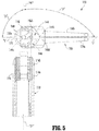
- first jaw member 150a can be pivoted separate and independent of second jaw member 150b, and vice versa. Additionally, and/or alternatively, first and second jaw members 150a, 150b can be simultaneously pivoted toward and/or away from one another as first and second jaw members 150a, 150b pivot between the closed and open conditions. In embodiments, first and second jaw members 150a, 150b can be pivoted up to a maximum jaw angle " ⁇ " of about 60 degrees, as depicted in FIG. 6 . As seen in FIGS. 4 , 6 , and 7 , as first and second jaw members 150a, 150b move between open and closed conditions, articulation member 140 slides along arcuate slot 156 between proximal and distal ends 156a, 156b thereof.
- jaw support shaft 170 may be disposed in proximal end 144a of elongate slot 144 and proximal ends of arcuate slots 156 of the pair of jaw members 150, while in one of the open conditions ( FIG. 6 and FIG. 7 ) jaw support shaft 170 may be disposed in distal end 144b of elongate slot 144 and distal ends of arcuate slots 156 of the pair of jaw members 150.
- pivoting movement of the pair of jaw members 150 to one of the open conditions thereof enables the pair of jaw members 150 and the articulation member 140 to axially translate along first longitudinal axis "X1-X1" in a proximal direction (toward wrist assembly 110) relative to line "L," jaw support shaft 170, and/or the pair of cam pulleys 160, and vice versa with regard to pivoting movement of the pair of jaw members 150 towards the closed condition.
- one or more components of end effector 100 can be simultaneously (and/or separately/independently), rotated, articulated, and/or pivoted.
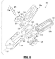
- jaw assembly 220 for connection to an end effector of robot arms 2, 3 and for manipulation by control device 4, in accordance with another embodiment of the present disclosure but not according to the invention, is generally designated as 220.
- Jaw assembly 220 may be substantially similar to jaw assembly 120 and thus will only be described in detail herein to the extent necessary to describe differences in construction and/or operation from those of jaw assembly 120.
- jaw assembly 220 may include a jaw housing 130, an articulating member 240, a pair of jaw members 250, a pair of cam pulleys 160, and a jaw support shaft 170.
- Articulating member 240 may include a pair of articulating pins 242 extending from opposed side surfaces thereof and defines an elongate slot 244 therethrough adapted and dimensioned to slidably receive jaw support shaft 170. As seen in FIG. 8 , each of the pair of articulating pins 242 may be positioned distally of elongate slot 244, and thus, distally of central long axis 170a of jaw support shaft 170, which as described above, may be aligned with second pivot axis "B-B" (see FIG. 2 ) when coupled to wrist assembly 110.
- the pair of jaw members 250 may include a first jaw member 250a and a second jaw member 250b. Each of the pair of jaw members 250 defines an arcuate slot 252 therethrough that may be adapted and dimensioned to receive jaw support shaft 170. Arcuate slot 252 may be adapted and dimensioned to enable jaw support shaft 170 to slide between proximal and distal ends of arcuate slot 252 as first and second jaw members 250a, 250b pivot about support shaft 170 relative to central long axis 170a of support shaft 170 (e.g., and second pivot axis "B-B" - see FIG. 2 ). An articulation pin opening 254 and a cam pin opening 256 are defined through each of the pair of jaw members 250.
- Each articulation pin opening 254 may be positioned on one of the pair of jaw members 250 to receive one of articulation pins 242 of articulation member 240 and enable articulation member 240 to articulate the pair of jaw members 250 relative to first longitudinal axis "X1-X1" similar to that described above with respect to articulation member 140.
- Each cam pin opening 256 may be positioned on one of the pair of jaw members 250 to receive one of cam pins 164 of cam pulleys 160 and enable cam pulleys 160 to pivot the pair of jaw members 250 between open and closed conditions similar to that described above with respect to the pair of jaw members 150.
- a jaw assembly for connection to an end effector of robot arms 2, 3 and for manipulation by control device 4, in accordance with an embodiment of the present invention may be generally designated as 320.
- Jaw assembly 320 may be substantially similar to jaw assemblies 120, 220 and thus will only be described in detail herein to the extent necessary to describe differences in construction and/or operation from those of jaw assemblies 120, 220.
- jaw assembly 320 includes a housing 330, a jaw support shaft 170, a pair of cam pulleys 340, and a pair of jaw members 350.
- the pair of cam pulleys 340 may include a first cam pulley 340a and a second cam pulley 340b. Each of the pair of cam pulleys 340 is mounted to the jaw support shaft 170 and has a body 342 defining a central bore 342a and a pulley pin slot 342b. The central bore 342 of each pulley 340 is adapted to receive the jaw support shaft 170 therethrough. The body 342 of each pulley 340 further defines a cable channel 344 that may be adapted to receive one or more cables therein, which may be at least partially wrapped around, and/or secured to/within, channel 344.
- first cable “C1” may be wrapped around first cam pulley 340a and a second cable “C2" may be wrapped around second cam pulley 340b.
- first cam pulley 340a may be wrapped around first cam pulley 340a and a second cable “C2" may be wrapped around second cam pulley 340b.
- two separate cables terminating on the pulley 340 may be used instead.
- the one or more cables may be movable (e.g. via a motor - see FIG. 1B ) to rotate or pivot one or both of the pair of cam pulleys 340a, 340b about jaw support shaft 170.
- the pair of jaw members 350 may include a first jaw member 350a and a second jaw member 350b.
- Each of the pair of jaw members 350 defines a support shaft slot 352 through a proximal portion thereof and includes a pulley pin 354 and a jaw pin 356 extending from the proximal portion on opposite side surfaces thereof.
- the support shaft slot 352 is adapted and dimensioned to receive jaw support shaft 170 and enable sliding movement of jaw support shaft 170 therein.
- support shaft slot 352 may be disposed off-center of a center of the proximal portion of one or both of the pair of jaw members 350.
- the support shaft slot 352 of one or both of the pair of jaw members 350 may be curvate and can include at least one nub 352a.
- Each of the pair of jaw members 350 defines a jaw pin slot 358 adapted to slidably receive an opposing one of the jaw pins 356 of the pair of jaw members 350.
- the jaw pin slot 358 can be curvate to provide a non-linear relationship between pulley angle (e.g., a rotational angle of one or both of the pair of pulleys) and jaw angle (e.g., a rotational angle of one or both of the pair of jaw members).
- one or more of slots 352 and/or 358 can be shaped to dictate a ratio and motion profile of one or both of the pair of jaw members 150 as one or both of the pair of cam pulleys 350 are actuated.
- One or more of slots 352 and/or 358 can have any suitable profile (e.g., elongate, circular, elliptical, c-shaped, s-shaped, etc.) to accommodate any suitable relationship (e.g., linear, non-linear) between pulley angle and jaw angle.
- the one or more cables are actuated to rotate one or both of the pair of cam pulleys 340 about jaw support shaft 170 such that jaw pins 356 slide in jaw pin slots 358 and at least one of the jaw members 350b slidingly pivots about jaw support shaft 170 via support shaft slot 352.
- movement (e.g., pivoting) of one or both of the pair of cam pulleys 340 imparts pivoting and/or articulating movement of the pair of jaw members 350 about jaw support shaft 170, depending upon the direction of rotation (e.g., clockwise/counterclockwise) and/or amount of rotational displacement of one or both of the pair of the pair of cam pulleys 350.
- the pair of jaw members 350 may be adapted to pivot between open and closed conditions similar to that described above with respect to the pair of jaw members 150.
- the first and second cam pulleys 350a, 350b can be rotated in the same and/or opposite directions with respect to one another to impart the pivoting and/or articulating movement of the pair of jaw members 350.
- the first and second cam pulleys 350a, 350b can be rotationally displaced at the same and/or different amounts to impart the pivoting and/or articulating movement of the pair of jaw members 350.
- support shaft slot 352 enable the pair of jaw members 350 to slidingly pivot/rotate about jaw support shaft 170 so that the first and second jaw members 350a, 350b approximate one another (e.g., toward the closed condition) in substantially parallel relation.
- the load distribution along tissue engaging surfaces 350c of the pair of jaw members 350 may vary in part depending on the shape of the support shaft slot 352 and the resultant angle and position of the pair of jaw members 350.
- any of the presently described jaw assemblies provide increased mechanical advantage with force multiplication features thereof (e.g., pins, slots, cables and/or combinations thereof) for improved grasping.
- multiplication of the pulley angle with respect to the jaw angle amplifies force at tips (e.g., distal ends) of the jaw members for an equivalent, or substantially equivalent, tension applied at a proximal end of one or more of the cables.
- This increased mechanical advantage enables a user to manipulate thick and heavy tissue by generating greater grasping force while minimizing tension in the cables and/or reducing mechanical stress on various components (e.g., cables, pulleys, etc.) of the end effector.
- force multiplication features enable the one or both of pair of jaw members to open by 40 degrees when one or more of the pulleys rotate by 80 degrees.
Landscapes
- Health & Medical Sciences (AREA)
- Life Sciences & Earth Sciences (AREA)
- Surgery (AREA)
- Engineering & Computer Science (AREA)
- Nuclear Medicine, Radiotherapy & Molecular Imaging (AREA)
- Animal Behavior & Ethology (AREA)
- Public Health (AREA)
- Heart & Thoracic Surgery (AREA)
- Medical Informatics (AREA)
- Molecular Biology (AREA)
- Veterinary Medicine (AREA)
- General Health & Medical Sciences (AREA)
- Biomedical Technology (AREA)
- Robotics (AREA)
- Gynecology & Obstetrics (AREA)
- Radiology & Medical Imaging (AREA)
- Oral & Maxillofacial Surgery (AREA)
- Pathology (AREA)
- Ophthalmology & Optometry (AREA)
- Manipulator (AREA)
- Surgical Instruments (AREA)
Claims (10)
- Effecteur terminal (320) d'un outil chirurgical comprenant :un boîtier (330) ayant des extrémités proximale et distale, le boîtier définissant un axe longitudinal qui s'étend à travers les extrémités proximale et distale ;un arbre de support de mâchoire (170) monté sur le boîtier et définissant un axe de pivotement qui s'étend à travers celui-ci ;une paire d'éléments de mâchoire (350) supportés sur l'arbre de support de mâchoire et pouvant pivoter autour de l'axe de pivotement, chacun de la paire d'éléments de mâchoire définissant une fente d'arbre de support (352) à travers celui-ci et comportant une broche de poulie (354) et une broche de mâchoire (356) s'étendant à partir de celui-ci, chacun de la paire d'éléments de mâchoire définissant une fente de broche de mâchoire (358) adaptée pour recevoir l'une opposée des broches de mâchoire de la paire d'éléments de mâchoire ;une paire de poulies à cames (340) montées sur l'arbre de support de mâchoire et accouplées à la paire d'éléments de mâchoire, la paire de poulies à cames pouvant tourner autour de l'axe de pivotement pour faire pivoter la paire d'éléments de support de mâchoire autour de l'arbre de support de mâchoire ;la fente d'arbre de support (352) est adaptée et dimensionnée pour recevoir l'arbre de support de mâchoire (170) et permettre un mouvement coulissant de l'arbre de support de mâchoire (170) à l'intérieur de celui-ci ;dans lequel chacune de la paire de poulies à cames comprend une fente de broche de poulie (342b), la fente de broche de poulie étant adaptée pour recevoir la broche de poulie d'un élément respectif de la paire d'éléments de mâchoire.
- Effecteur terminal selon la revendication 1, dans lequel la fente de broche de mâchoire est incurvée.
- Effecteur terminal selon la revendication 1 ou la revendication 2, dans lequel la fente d'arbre de support de chacun de la paire d'éléments de mâchoire est incurvée.
- Effecteur terminal selon la revendication 1, dans lequel l'effecteur terminal est un effecteur terminal de préhension et chaque élément de mâchoire comporte des dents (154a) disposées sur une surface de préhension.
- Effecteur terminal selon l'une quelconque des revendications précédentes, dans lequel au moins un câble (C1, C2) est fixé à la paire de poulies à cames, l'au moins un câble étant mobile pour faire tourner au moins l'une de la paire de poulies à cames afin de pivoter au niveau de au moins l'un de la paire d'éléments de mâchoire autour de l'axe de pivotement.
- Effecteur terminal selon l'une quelconque des revendications précédentes, dans lequel au moins un premier câble (C1) est accouplé à une première de la paire de poulies à cames (340a) et au moins un second câble (C2) est accouplé à un second câble parmi la paire de poulies à cames (340b), la première de la paire de poulies à cames et la seconde de la paire de poulies à cames étant accouplées à au moins un moteur de sorte que l'actionnement de l'au moins un moteur effectue : (1) un mouvement d'articulation et/ou (2) un mouvement de pivotement de la paire d'éléments de mâchoire.
- Effecteur terminal selon l'une quelconque des revendications précédentes, dans lequel l'axe de pivotement est transversal à l'axe longitudinal.
- Effecteur terminal selon la revendication 1 destiné à être utilisé et relié à un bras de robot d'un système chirurgical robotique, l'effecteur terminal étant commandé par au moins un câble (C1, C2) s'étendant à partir d'au moins un moteur d'un dispositif de commande du système chirurgical robotique.
- Effecteur terminal selon la revendication 8, dans lequel l'au moins un câble est fixé à la paire de poulies à cames, l'au moins un câble étant mobile pour faire tourner au moins l'une de la paire de poulies à cames afin de faire pivoter au moins l'une de la paire d'éléments de mâchoire autour de l'axe de pivotement.
- Effecteur terminal selon la revendication 8 ou 9, dans lequel l'au moins un câble comprend au moins un premier câble (C1) qui est accouplé à un premier (340a) de la paire de poulies à cames et au moins un second câble (C2) qui est accouplé à une seconde (340b) de la paire de poulies à cames, la première de la paire de poulies à cames et la seconde de la paire de poulies à cames étant accouplées à l'au moins un moteur.
Applications Claiming Priority (2)
| Application Number | Priority Date | Filing Date | Title |
|---|---|---|---|
| US201462036904P | 2014-08-13 | 2014-08-13 | |
| PCT/US2015/041442 WO2016025134A2 (fr) | 2014-08-13 | 2015-07-22 | Commande robotisée de préhension à avantage mécanique |
Publications (3)
| Publication Number | Publication Date |
|---|---|
| EP3179955A2 EP3179955A2 (fr) | 2017-06-21 |
| EP3179955A4 EP3179955A4 (fr) | 2018-04-18 |
| EP3179955B1 true EP3179955B1 (fr) | 2021-09-15 |
Family
ID=55304738
Family Applications (1)
| Application Number | Title | Priority Date | Filing Date |
|---|---|---|---|
| EP15831995.4A Active EP3179955B1 (fr) | 2014-08-13 | 2015-07-22 | Commande robotisée de préhension à avantage mécanique |
Country Status (7)
| Country | Link |
|---|---|
| US (2) | US10390853B2 (fr) |
| EP (1) | EP3179955B1 (fr) |
| JP (2) | JP6734259B2 (fr) |
| CN (2) | CN106659538B (fr) |
| AU (1) | AU2015302216B2 (fr) |
| CA (1) | CA2957750C (fr) |
| WO (1) | WO2016025134A2 (fr) |
Families Citing this family (25)
| Publication number | Priority date | Publication date | Assignee | Title |
|---|---|---|---|---|
| EP3179955B1 (fr) | 2014-08-13 | 2021-09-15 | Covidien LP | Commande robotisée de préhension à avantage mécanique |
| CN106572889B (zh) * | 2014-08-13 | 2019-09-06 | 柯惠Lp公司 | 机器人控制的具有机械优势的夹持 |
| AU2016282591B2 (en) * | 2015-06-23 | 2020-04-23 | Covidien Lp | Surgical end effectors with mechanical advantage |
| ITUB20154977A1 (it) | 2015-10-16 | 2017-04-16 | Medical Microinstruments S R L | Strumento medicale e metodo di fabbricazione di detto strumento medicale |
| JP6748729B2 (ja) * | 2016-10-20 | 2020-09-02 | オリンパス株式会社 | 揺動機構および把持具 |
| US10743948B2 (en) * | 2016-12-07 | 2020-08-18 | Ethicon Llc | Surgical tool wrists |
| EP3348213A1 (fr) * | 2017-01-13 | 2018-07-18 | Spinal Stabilization Technologies Ltd | Instruments chirurgicaux articulés tels que pinces-gouges |
| JP6811676B2 (ja) * | 2017-05-01 | 2021-01-13 | 株式会社メディカロイド | 駆動部材、駆動機構、および駆動機構の製造方法 |
| US11364067B2 (en) * | 2017-10-06 | 2022-06-21 | Cilag Gmbh International | Electrical isolation of electrosurgical instruments |
| US10779839B2 (en) * | 2018-02-08 | 2020-09-22 | Ethicon Llc | Surgical clip applier with parallel closure jaws |
| US11317962B2 (en) * | 2018-05-04 | 2022-05-03 | Ethicon Llc | Dual axle robotic end effector |
| CN112218596B (zh) | 2018-06-07 | 2025-05-16 | 奥瑞斯健康公司 | 具有高力器械的机器人医疗系统 |
| US11304704B2 (en) * | 2018-08-22 | 2022-04-19 | Covidien Lp | Surgical clip applier and ligation clips |
| US11147566B2 (en) | 2018-10-01 | 2021-10-19 | Covidien Lp | Endoscopic surgical clip applier |
| EP4110221A1 (fr) | 2020-02-26 | 2023-01-04 | Covidien LP | Instrument chirurgical robotique comprenant des codeurs linéaires pour mesurer un déplacement de câble |
| US11896333B2 (en) * | 2020-08-19 | 2024-02-13 | Covidien Lp | Robotic surgical instrument |
| CN112545612B (zh) * | 2020-12-04 | 2022-11-01 | 哈尔滨工业大学 | 一种单孔手术机械臂的钳头机构 |
| CA3203061A1 (fr) * | 2020-12-22 | 2022-06-30 | Peter Francis | Pointe pour instrument chirurgical et procedes associes |
| US12035993B2 (en) * | 2021-01-21 | 2024-07-16 | Cilag Gmbh International | Multi-function actuation and articulation end effectors |
| GB2603929B (en) * | 2021-02-19 | 2023-06-14 | Prec Robotics Limited | An actuation mechanism |
| DK181495B1 (en) * | 2021-05-10 | 2024-03-12 | Flexlogical Aps | End effector for minimally invasive surgery |
| US12279842B2 (en) | 2021-11-03 | 2025-04-22 | Cilag Gmbh International | Surgical tool end effectors with distal wedge slot constraint |
| US12285230B2 (en) * | 2021-11-03 | 2025-04-29 | Cilag Gmbh International | Surgical tool end effectors with alignment arms |
| WO2024079670A1 (fr) * | 2022-10-12 | 2024-04-18 | Multi-Scale Medical Robotics Center Limited | Effecteur pour systèmes robotiques |
| ES2988236B2 (es) * | 2023-11-27 | 2025-06-10 | Servocad Microtronics S L | Cabezal para un instrumento quirúrgico laparoscópico |
Family Cites Families (231)
| Publication number | Priority date | Publication date | Assignee | Title |
|---|---|---|---|---|
| US5207114A (en) * | 1988-04-21 | 1993-05-04 | Massachusetts Institute Of Technology | Compact cable transmission with cable differential |
| US5762458A (en) | 1996-02-20 | 1998-06-09 | Computer Motion, Inc. | Method and apparatus for performing minimally invasive cardiac procedures |
| US5382253A (en) | 1993-03-05 | 1995-01-17 | Unisurge, Inc. | Clip applier tool |
| US5507773A (en) | 1994-02-18 | 1996-04-16 | Ethicon Endo-Surgery | Cable-actuated jaw assembly for surgical instruments |
| US5569299A (en) | 1995-03-01 | 1996-10-29 | Symbiosis Corporation | Endoscopic urological biopsy forceps |
| US5710870A (en) | 1995-09-07 | 1998-01-20 | California Institute Of Technology | Decoupled six degree-of-freedom robot manipulator |
| US5855583A (en) | 1996-02-20 | 1999-01-05 | Computer Motion, Inc. | Method and apparatus for performing minimally invasive cardiac procedures |
| US5792135A (en) | 1996-05-20 | 1998-08-11 | Intuitive Surgical, Inc. | Articulated surgical instrument for performing minimally invasive surgery with enhanced dexterity and sensitivity |
| US6364888B1 (en) | 1996-09-09 | 2002-04-02 | Intuitive Surgical, Inc. | Alignment of master and slave in a minimally invasive surgical apparatus |
| US6132441A (en) | 1996-11-22 | 2000-10-17 | Computer Motion, Inc. | Rigidly-linked articulating wrist with decoupled motion transmission |
| US8182469B2 (en) | 1997-11-21 | 2012-05-22 | Intuitive Surgical Operations, Inc. | Surgical accessory clamp and method |
| US8529582B2 (en) | 1996-12-12 | 2013-09-10 | Intuitive Surgical Operations, Inc. | Instrument interface of a robotic surgical system |
| US6331181B1 (en) | 1998-12-08 | 2001-12-18 | Intuitive Surgical, Inc. | Surgical robotic tools, data architecture, and use |
| US7699855B2 (en) | 1996-12-12 | 2010-04-20 | Intuitive Surgical Operations, Inc. | Sterile surgical adaptor |
| US7666191B2 (en) | 1996-12-12 | 2010-02-23 | Intuitive Surgical, Inc. | Robotic surgical system with sterile surgical adaptor |
| US7727244B2 (en) | 1997-11-21 | 2010-06-01 | Intuitive Surgical Operation, Inc. | Sterile surgical drape |
| US6132368A (en) | 1996-12-12 | 2000-10-17 | Intuitive Surgical, Inc. | Multi-component telepresence system and method |
| US8206406B2 (en) | 1996-12-12 | 2012-06-26 | Intuitive Surgical Operations, Inc. | Disposable sterile surgical adaptor |
| US6019780A (en) * | 1996-12-17 | 2000-02-01 | Tnco, Inc. | Dual pin and groove pivot for micro-instrument |
| US6714839B2 (en) | 1998-12-08 | 2004-03-30 | Intuitive Surgical, Inc. | Master having redundant degrees of freedom |
| US6554844B2 (en) | 1998-02-24 | 2003-04-29 | Endovia Medical, Inc. | Surgical instrument |
| US6246200B1 (en) | 1998-08-04 | 2001-06-12 | Intuitive Surgical, Inc. | Manipulator positioning linkage for robotic surgery |
| US8600551B2 (en) | 1998-11-20 | 2013-12-03 | Intuitive Surgical Operations, Inc. | Medical robotic system with operatively couplable simulator unit for surgeon training |
| US6951535B2 (en) | 2002-01-16 | 2005-10-04 | Intuitive Surgical, Inc. | Tele-medicine system that transmits an entire state of a subsystem |
| US6459926B1 (en) | 1998-11-20 | 2002-10-01 | Intuitive Surgical, Inc. | Repositioning and reorientation of master/slave relationship in minimally invasive telesurgery |
| US6659939B2 (en) | 1998-11-20 | 2003-12-09 | Intuitive Surgical, Inc. | Cooperative minimally invasive telesurgical system |
| US7125403B2 (en) | 1998-12-08 | 2006-10-24 | Intuitive Surgical | In vivo accessories for minimally invasive robotic surgery |
| US6493608B1 (en) | 1999-04-07 | 2002-12-10 | Intuitive Surgical, Inc. | Aspects of a control system of a minimally invasive surgical apparatus |
| US6799065B1 (en) | 1998-12-08 | 2004-09-28 | Intuitive Surgical, Inc. | Image shifting apparatus and method for a telerobotic system |
| US6770081B1 (en) | 2000-01-07 | 2004-08-03 | Intuitive Surgical, Inc. | In vivo accessories for minimally invasive robotic surgery and methods |
| US6394998B1 (en) * | 1999-01-22 | 2002-05-28 | Intuitive Surgical, Inc. | Surgical tools for use in minimally invasive telesurgical applications |
| US8944070B2 (en) | 1999-04-07 | 2015-02-03 | Intuitive Surgical Operations, Inc. | Non-force reflecting method for providing tool force information to a user of a telesurgical system |
| US6594552B1 (en) | 1999-04-07 | 2003-07-15 | Intuitive Surgical, Inc. | Grip strength with tactile feedback for robotic surgery |
| US6424885B1 (en) | 1999-04-07 | 2002-07-23 | Intuitive Surgical, Inc. | Camera referenced control in a minimally invasive surgical apparatus |
| US6565554B1 (en) | 1999-04-07 | 2003-05-20 | Intuitive Surgical, Inc. | Friction compensation in a minimally invasive surgical apparatus |
| US6793652B1 (en) | 1999-06-02 | 2004-09-21 | Power Medical Interventions, Inc. | Electro-mechanical surgical device |
| US6716233B1 (en) | 1999-06-02 | 2004-04-06 | Power Medical Interventions, Inc. | Electromechanical driver and remote surgical instrument attachment having computer assisted control capabilities |
| US7695485B2 (en) | 2001-11-30 | 2010-04-13 | Power Medical Interventions, Llc | Surgical device |
| US6315184B1 (en) | 1999-06-02 | 2001-11-13 | Powermed, Inc. | Stapling device for use with an electromechanical driver device for use with anastomosing, stapling, and resecting instruments |
| US8004229B2 (en) | 2005-05-19 | 2011-08-23 | Intuitive Surgical Operations, Inc. | Software center and highly configurable robotic systems for surgery and other uses |
| US7594912B2 (en) | 2004-09-30 | 2009-09-29 | Intuitive Surgical, Inc. | Offset remote center manipulator for robotic surgery |
| US10188471B2 (en) | 1999-09-17 | 2019-01-29 | Intuitive Surgical Operations, Inc. | Tele-operative surgical systems and methods of control at joint limits using inverse kinematics |
| US8768516B2 (en) | 2009-06-30 | 2014-07-01 | Intuitive Surgical Operations, Inc. | Control of medical robotic system manipulator about kinematic singularities |
| US6312435B1 (en) | 1999-10-08 | 2001-11-06 | Intuitive Surgical, Inc. | Surgical instrument with extended reach for use in minimally invasive surgery |
| US6206903B1 (en) | 1999-10-08 | 2001-03-27 | Intuitive Surgical, Inc. | Surgical tool with mechanical advantage |
| US6491691B1 (en) | 1999-10-08 | 2002-12-10 | Intuitive Surgical, Inc. | Minimally invasive surgical hook apparatus and method for using same |
| US6645196B1 (en) | 2000-06-16 | 2003-11-11 | Intuitive Surgical, Inc. | Guided tool change |
| US6746443B1 (en) | 2000-07-27 | 2004-06-08 | Intuitive Surgical Inc. | Roll-pitch-roll surgical tool |
| US6902560B1 (en) * | 2000-07-27 | 2005-06-07 | Intuitive Surgical, Inc. | Roll-pitch-roll surgical tool |
| JP4014792B2 (ja) | 2000-09-29 | 2007-11-28 | 株式会社東芝 | マニピュレータ |
| US6840938B1 (en) | 2000-12-29 | 2005-01-11 | Intuitive Surgical, Inc. | Bipolar cauterizing instrument |
| US20030135204A1 (en) | 2001-02-15 | 2003-07-17 | Endo Via Medical, Inc. | Robotically controlled medical instrument with a flexible section |
| US7699835B2 (en) | 2001-02-15 | 2010-04-20 | Hansen Medical, Inc. | Robotically controlled surgical instruments |
| DE60218240T2 (de) | 2001-04-18 | 2007-11-22 | Olympus Corporation | Chirurgisches Instrument |
| US6994708B2 (en) | 2001-04-19 | 2006-02-07 | Intuitive Surgical | Robotic tool with monopolar electro-surgical scissors |
| US7824401B2 (en) | 2004-10-08 | 2010-11-02 | Intuitive Surgical Operations, Inc. | Robotic tool with wristed monopolar electrosurgical end effectors |
| US8398634B2 (en) | 2002-04-18 | 2013-03-19 | Intuitive Surgical Operations, Inc. | Wristed robotic surgical tool for pluggable end-effectors |
| US6783524B2 (en) | 2001-04-19 | 2004-08-31 | Intuitive Surgical, Inc. | Robotic surgical tool with ultrasound cauterizing and cutting instrument |
| US7607440B2 (en) | 2001-06-07 | 2009-10-27 | Intuitive Surgical, Inc. | Methods and apparatus for surgical planning |
| US6817974B2 (en) | 2001-06-29 | 2004-11-16 | Intuitive Surgical, Inc. | Surgical tool having positively positionable tendon-actuated multi-disk wrist joint |
| ATE547992T1 (de) | 2001-06-29 | 2012-03-15 | Intuitive Surgical Operations | Gelenkmechanismus fuer plattformverbindung |
| US6676684B1 (en) | 2001-09-04 | 2004-01-13 | Intuitive Surgical, Inc. | Roll-pitch-roll-yaw surgical tool |
| US6728599B2 (en) | 2001-09-07 | 2004-04-27 | Computer Motion, Inc. | Modularity system for computer assisted surgery |
| AU2002365604A1 (en) | 2001-12-04 | 2003-06-17 | Power Medical Interventions Inc. | System and method for calibrating a surgical instrument |
| US6839612B2 (en) | 2001-12-07 | 2005-01-04 | Institute Surgical, Inc. | Microwrist system for surgical procedures |
| US6793653B2 (en) | 2001-12-08 | 2004-09-21 | Computer Motion, Inc. | Multifunctional handle for a medical robotic system |
| JP3912251B2 (ja) | 2002-10-02 | 2007-05-09 | 株式会社日立製作所 | マニピュレータ |
| US7386365B2 (en) | 2004-05-04 | 2008-06-10 | Intuitive Surgical, Inc. | Tool grip calibration for robotic surgery |
| EP3498213A3 (fr) | 2002-12-06 | 2019-07-03 | Intuitive Surgical Operations, Inc. | Poignée fléxible pour outil chirurgical |
| US8882657B2 (en) | 2003-03-07 | 2014-11-11 | Intuitive Surgical Operations, Inc. | Instrument having radio frequency identification systems and methods for use |
| US7105000B2 (en) | 2003-03-25 | 2006-09-12 | Ethicon Endo-Surgery, Inc. | Surgical jaw assembly with increased mechanical advantage |
| US7410483B2 (en) | 2003-05-23 | 2008-08-12 | Novare Surgical Systems, Inc. | Hand-actuated device for remote manipulation of a grasping tool |
| US9002518B2 (en) | 2003-06-30 | 2015-04-07 | Intuitive Surgical Operations, Inc. | Maximum torque driving of robotic surgical tools in robotic surgical systems |
| US20050165429A1 (en) | 2004-01-23 | 2005-07-28 | Peter Douglas | Surgical clamp possessing a combined parallel and scissor style clamp head |
| US7379790B2 (en) | 2004-05-04 | 2008-05-27 | Intuitive Surgical, Inc. | Tool memory-based software upgrades for robotic surgery |
| EP1750608B1 (fr) | 2004-06-02 | 2012-10-03 | Medtronic, Inc. | Dispositif d'ablation comprenant des machoires |
| US7947034B2 (en) | 2004-07-30 | 2011-05-24 | Tyco Healthcare Group Lp | Flexible shaft extender and method of using same |
| JP4373879B2 (ja) | 2004-08-26 | 2009-11-25 | 株式会社日立製作所 | 手術器具 |
| US9261172B2 (en) | 2004-09-30 | 2016-02-16 | Intuitive Surgical Operations, Inc. | Multi-ply strap drive trains for surgical robotic arms |
| US7628792B2 (en) | 2004-10-08 | 2009-12-08 | Covidien Ag | Bilateral foot jaws |
| US8876820B2 (en) | 2004-10-20 | 2014-11-04 | Atricure, Inc. | Surgical clamp |
| JP4287354B2 (ja) | 2004-10-25 | 2009-07-01 | 株式会社日立製作所 | 手術器具 |
| US9700334B2 (en) | 2004-11-23 | 2017-07-11 | Intuitive Surgical Operations, Inc. | Articulating mechanisms and link systems with torque transmission in remote manipulation of instruments and tools |
| US8465474B2 (en) | 2009-05-19 | 2013-06-18 | Intuitive Surgical Operations, Inc. | Cleaning of a surgical instrument force sensor |
| US8496647B2 (en) | 2007-12-18 | 2013-07-30 | Intuitive Surgical Operations, Inc. | Ribbed force sensor |
| US8147503B2 (en) | 2007-09-30 | 2012-04-03 | Intuitive Surgical Operations Inc. | Methods of locating and tracking robotic instruments in robotic surgical systems |
| US8108072B2 (en) | 2007-09-30 | 2012-01-31 | Intuitive Surgical Operations, Inc. | Methods and systems for robotic instrument tool tracking with adaptive fusion of kinematics information and image information |
| US8398541B2 (en) | 2006-06-06 | 2013-03-19 | Intuitive Surgical Operations, Inc. | Interactive user interfaces for robotic minimally invasive surgical systems |
| EP3395508A1 (fr) | 2005-06-30 | 2018-10-31 | Intuitive Surgical Operations Inc. | Indicateur pour communication d'état d'outil en téléchirurgie robotique multibras |
| US8273076B2 (en) | 2005-06-30 | 2012-09-25 | Intuitive Surgical Operations, Inc. | Indicator for tool state and communication in multi-arm robotic telesurgery |
| US8079950B2 (en) | 2005-09-29 | 2011-12-20 | Intuitive Surgical Operations, Inc. | Autofocus and/or autoscaling in telesurgery |
| CA2561034C (fr) | 2005-09-30 | 2014-12-09 | Sherwood Services Ag | Catheter endoscopique flexible avec un effecteur terminal pouvant coaguler et couper les tissus |
| US7819859B2 (en) | 2005-12-20 | 2010-10-26 | Intuitive Surgical Operations, Inc. | Control system for reducing internally generated frictional and inertial resistance to manual positioning of a surgical manipulator |
| US7689320B2 (en) | 2005-12-20 | 2010-03-30 | Intuitive Surgical Operations, Inc. | Robotic surgical system with joint motion controller adapted to reduce instrument tip vibrations |
| WO2007111749A2 (fr) | 2005-12-20 | 2007-10-04 | Intuitive Surgical, Inc. | Procede de manipulation d'une commande par un operateur depassant une limite d'un etat d'un dispositif medical dans un systeme medical robotique |
| ATE547059T1 (de) | 2005-12-20 | 2012-03-15 | Intuitive Surgical Operations | Instrumentenschnittstelle eines roboter- chirurgiesystems |
| US8182470B2 (en) | 2005-12-20 | 2012-05-22 | Intuitive Surgical Operations, Inc. | Telescoping insertion axis of a robotic surgical system |
| US7762825B2 (en) | 2005-12-20 | 2010-07-27 | Intuitive Surgical Operations, Inc. | Electro-mechanical interfaces to mount robotic surgical arms |
| US7453227B2 (en) | 2005-12-20 | 2008-11-18 | Intuitive Surgical, Inc. | Medical robotic system with sliding mode control |
| US7741802B2 (en) | 2005-12-20 | 2010-06-22 | Intuitive Surgical Operations, Inc. | Medical robotic system with programmably controlled constraints on error dynamics |
| US8054752B2 (en) | 2005-12-22 | 2011-11-08 | Intuitive Surgical Operations, Inc. | Synchronous data communication |
| US7757028B2 (en) | 2005-12-22 | 2010-07-13 | Intuitive Surgical Operations, Inc. | Multi-priority messaging |
| US7756036B2 (en) | 2005-12-22 | 2010-07-13 | Intuitive Surgical Operations, Inc. | Synchronous data communication |
| US8628518B2 (en) | 2005-12-30 | 2014-01-14 | Intuitive Surgical Operations, Inc. | Wireless force sensor on a distal portion of a surgical instrument and method |
| US7930065B2 (en) | 2005-12-30 | 2011-04-19 | Intuitive Surgical Operations, Inc. | Robotic surgery system including position sensors using fiber bragg gratings |
| US7907166B2 (en) | 2005-12-30 | 2011-03-15 | Intuitive Surgical Operations, Inc. | Stereo telestration for robotic surgery |
| US7835823B2 (en) | 2006-01-05 | 2010-11-16 | Intuitive Surgical Operations, Inc. | Method for tracking and reporting usage events to determine when preventive maintenance is due for a medical robotic system |
| US8597182B2 (en) | 2006-04-28 | 2013-12-03 | Intuitive Surgical Operations, Inc. | Robotic endoscopic retractor for use in minimally invasive surgery |
| EP2038712B2 (fr) | 2006-06-13 | 2019-08-28 | Intuitive Surgical Operations, Inc. | Système de commande configuré pour compenser des caractéristiques de liaison d'actionneur au joint non idéales dans un système robotique médical |
| US8597280B2 (en) | 2006-06-13 | 2013-12-03 | Intuitive Surgical Operations, Inc. | Surgical instrument actuator |
| US20080064927A1 (en) | 2006-06-13 | 2008-03-13 | Intuitive Surgical, Inc. | Minimally invasrive surgery guide tube |
| US9718190B2 (en) | 2006-06-29 | 2017-08-01 | Intuitive Surgical Operations, Inc. | Tool position and identification indicator displayed in a boundary area of a computer display screen |
| US20090192523A1 (en) | 2006-06-29 | 2009-07-30 | Intuitive Surgical, Inc. | Synthetic representation of a surgical instrument |
| US10008017B2 (en) | 2006-06-29 | 2018-06-26 | Intuitive Surgical Operations, Inc. | Rendering tool information as graphic overlays on displayed images of tools |
| US8151661B2 (en) | 2006-06-30 | 2012-04-10 | Intuituve Surgical Operations, Inc. | Compact capstan |
| US7391173B2 (en) | 2006-06-30 | 2008-06-24 | Intuitive Surgical, Inc | Mechanically decoupled capstan drive |
| WO2008045333A2 (fr) | 2006-10-05 | 2008-04-17 | Tyco Healthcare Group Lp | Dispositifs de suture endoscopique souples |
| US7736254B2 (en) | 2006-10-12 | 2010-06-15 | Intuitive Surgical Operations, Inc. | Compact cable tension tender device |
| US7935130B2 (en) | 2006-11-16 | 2011-05-03 | Intuitive Surgical Operations, Inc. | Two-piece end-effectors for robotic surgical tools |
| US9226648B2 (en) | 2006-12-21 | 2016-01-05 | Intuitive Surgical Operations, Inc. | Off-axis visualization systems |
| US9084623B2 (en) | 2009-08-15 | 2015-07-21 | Intuitive Surgical Operations, Inc. | Controller assisted reconfiguration of an articulated instrument during movement into and out of an entry guide |
| US8903546B2 (en) | 2009-08-15 | 2014-12-02 | Intuitive Surgical Operations, Inc. | Smooth control of an articulated instrument across areas with different work space conditions |
| US9138129B2 (en) | 2007-06-13 | 2015-09-22 | Intuitive Surgical Operations, Inc. | Method and system for moving a plurality of articulated instruments in tandem back towards an entry guide |
| US8620473B2 (en) | 2007-06-13 | 2013-12-31 | Intuitive Surgical Operations, Inc. | Medical robotic system with coupled control modes |
| US9096033B2 (en) | 2007-06-13 | 2015-08-04 | Intuitive Surgical Operations, Inc. | Surgical system instrument sterile adapter |
| JP2009028156A (ja) | 2007-07-25 | 2009-02-12 | Terumo Corp | 医療用マニピュレータ及びその洗浄方法 |
| US8262655B2 (en) | 2007-11-21 | 2012-09-11 | Ethicon Endo-Surgery, Inc. | Bipolar forceps |
| US8224484B2 (en) | 2007-09-30 | 2012-07-17 | Intuitive Surgical Operations, Inc. | Methods of user interface with alternate tool mode for robotic surgical tools |
| US8012170B2 (en) | 2009-04-27 | 2011-09-06 | Tyco Healthcare Group Lp | Device and method for controlling compression of tissue |
| KR100911248B1 (ko) * | 2007-10-17 | 2009-08-07 | 국립암센터 | 소구경 복강경 수술기구 |
| JP5128904B2 (ja) | 2007-10-31 | 2013-01-23 | 株式会社東芝 | マニピュレータ |
| US8561473B2 (en) | 2007-12-18 | 2013-10-22 | Intuitive Surgical Operations, Inc. | Force sensor temperature compensation |
| US8808164B2 (en) | 2008-03-28 | 2014-08-19 | Intuitive Surgical Operations, Inc. | Controlling a robotic surgical tool with a display monitor |
| US8155479B2 (en) | 2008-03-28 | 2012-04-10 | Intuitive Surgical Operations Inc. | Automated panning and digital zooming for robotic surgical systems |
| US7843158B2 (en) | 2008-03-31 | 2010-11-30 | Intuitive Surgical Operations, Inc. | Medical robotic system adapted to inhibit motions resulting in excessive end effector forces |
| US7886743B2 (en) | 2008-03-31 | 2011-02-15 | Intuitive Surgical Operations, Inc. | Sterile drape interface for robotic surgical instrument |
| US9895813B2 (en) | 2008-03-31 | 2018-02-20 | Intuitive Surgical Operations, Inc. | Force and torque sensing in a surgical robot setup arm |
| US8568443B1 (en) | 2008-05-21 | 2013-10-29 | Encision, Inc. | Surgical grapser tool and actuation mechanism |
| EP2300724A1 (fr) | 2008-06-27 | 2011-03-30 | Allegiance Corporation | Élément flexible de type poignée et procédés de fabrication et d'utilisation de celui-ci |
| US9265567B2 (en) | 2008-06-30 | 2016-02-23 | Intuitive Surgical Operations, Inc. | Vessel sealing instrument with stepped jaw |
| US8540748B2 (en) | 2008-07-07 | 2013-09-24 | Intuitive Surgical Operations, Inc. | Surgical instrument wrist |
| US9204923B2 (en) | 2008-07-16 | 2015-12-08 | Intuitive Surgical Operations, Inc. | Medical instrument electronically energized using drive cables |
| US8821480B2 (en) | 2008-07-16 | 2014-09-02 | Intuitive Surgical Operations, Inc. | Four-cable wrist with solid surface cable channels |
| JP2010075242A (ja) | 2008-09-24 | 2010-04-08 | Terumo Corp | 医療用マニピュレータ |
| US8315720B2 (en) | 2008-09-26 | 2012-11-20 | Intuitive Surgical Operations, Inc. | Method for graphically providing continuous change of state directions to a user of a medical robotic system |
| US9687986B2 (en) | 2008-11-11 | 2017-06-27 | Intuitive Surgical Operations, Inc. | Robotic linkage |
| US8161838B2 (en) | 2008-12-22 | 2012-04-24 | Intuitive Surgical Operations, Inc. | Method and apparatus for reducing at least one friction force opposing an axial force exerted through an actuator element |
| US8335590B2 (en) | 2008-12-23 | 2012-12-18 | Intuitive Surgical Operations, Inc. | System and method for adjusting an image capturing device attribute using an unused degree-of-freedom of a master control device |
| US8245594B2 (en) | 2008-12-23 | 2012-08-21 | Intuitive Surgical Operations, Inc. | Roll joint and method for a surgical apparatus |
| US8374723B2 (en) | 2008-12-31 | 2013-02-12 | Intuitive Surgical Operations, Inc. | Obtaining force information in a minimally invasive surgical procedure |
| US8594841B2 (en) | 2008-12-31 | 2013-11-26 | Intuitive Surgical Operations, Inc. | Visual force feedback in a minimally invasive surgical procedure |
| US8523900B2 (en) | 2009-02-03 | 2013-09-03 | Terumo Kabushiki Kaisha | Medical manipulator |
| US8858547B2 (en) | 2009-03-05 | 2014-10-14 | Intuitive Surgical Operations, Inc. | Cut and seal instrument |
| US8418073B2 (en) | 2009-03-09 | 2013-04-09 | Intuitive Surgical Operations, Inc. | User interfaces for electrosurgical tools in robotic surgical systems |
| US8120301B2 (en) | 2009-03-09 | 2012-02-21 | Intuitive Surgical Operations, Inc. | Ergonomic surgeon control console in robotic surgical systems |
| US8423182B2 (en) | 2009-03-09 | 2013-04-16 | Intuitive Surgical Operations, Inc. | Adaptable integrated energy control system for electrosurgical tools in robotic surgical systems |
| JP2010220786A (ja) | 2009-03-24 | 2010-10-07 | Waseda Univ | 手術用マニピュレータ及び手術用マニピュレータシステム |
| US8690909B2 (en) | 2009-05-22 | 2014-04-08 | Charles R. Slater | Endoscopic instrument with bi-laterally widened cam-slot at end effector |
| US8333780B1 (en) | 2009-06-05 | 2012-12-18 | Okay Industries, Inc. | Surgical tool and method of operation |
| US8423186B2 (en) | 2009-06-30 | 2013-04-16 | Intuitive Surgical Operations, Inc. | Ratcheting for master alignment of a teleoperated minimally-invasive surgical instrument |
| CN201544225U (zh) * | 2009-11-03 | 2010-08-11 | 昆山市工业技术研究院有限责任公司 | 一种用于辅助外科手术的电动锁紧支架 |
| EP2594222B1 (fr) | 2009-11-13 | 2018-10-03 | Intuitive Surgical Operations, Inc. | Outil chirurgical doté d'une poignée compacte |
| US20110118708A1 (en) | 2009-11-13 | 2011-05-19 | Intuitive Surgical Operations, Inc. | Double universal joint |
| KR102077004B1 (ko) | 2009-11-13 | 2020-02-13 | 인튜어티브 서지컬 오퍼레이션즈 인코포레이티드 | 여분의 닫힘 메커니즘을 구비한 단부 작동기 |
| US8668638B2 (en) | 2010-02-11 | 2014-03-11 | Intuitive Surgical Operations, Inc. | Method and system for automatically maintaining an operator selected roll orientation at a distal tip of a robotic endoscope |
| US8623044B2 (en) | 2010-04-12 | 2014-01-07 | Ethicon Endo-Surgery, Inc. | Cable actuated end-effector for a surgical instrument |
| US10265118B2 (en) * | 2010-05-04 | 2019-04-23 | Covidien Lp | Pinion blade drive mechanism for a laparoscopic vessel dissector |
| US8394120B2 (en) | 2010-05-04 | 2013-03-12 | Jacek Krzyzanowski | End effector assembly with increased clamping force for a surgical instrument |
| US8644988B2 (en) | 2010-05-14 | 2014-02-04 | Intuitive Surgical Operations, Inc. | Drive force control in medical instrument providing position measurements |
| US9019345B2 (en) | 2010-07-02 | 2015-04-28 | Intuitive Surgical Operations, Inc. | Imaging mode blooming suppression |
| EP2590586B1 (fr) | 2010-07-09 | 2014-08-06 | Intuitive Surgical Operations, Inc. | Couverture d'outil électrochirurgical |
| US8663270B2 (en) | 2010-07-23 | 2014-03-04 | Conmed Corporation | Jaw movement mechanism and method for a surgical tool |
| JP5835906B2 (ja) | 2010-09-30 | 2015-12-24 | オリンパス株式会社 | 屈曲関節機構並びにその屈曲関節機構を有する術具及びその屈曲関節機構を有するマニピュレータ |
| DE102010043584A1 (de) | 2010-11-08 | 2012-05-10 | Kuka Laboratories Gmbh | Medizinscher Arbeitsplatz |
| CN105748152B (zh) | 2010-11-15 | 2018-06-26 | 直观外科手术操作公司 | 在手术仪器中去耦仪器轴滚动和末端执行器促动 |
| US9241766B2 (en) | 2010-12-22 | 2016-01-26 | Intuitive Surgical Operations, Inc. | Alternate instrument removal |
| CN102028548B (zh) * | 2011-01-14 | 2012-03-07 | 哈尔滨工业大学 | 腹腔微创手术机器人用夹钳式手术器械 |
| US9393017B2 (en) | 2011-02-15 | 2016-07-19 | Intuitive Surgical Operations, Inc. | Methods and systems for detecting staple cartridge misfire or failure |
| EP2675365B1 (fr) | 2011-02-15 | 2018-04-25 | Intuitive Surgical Operations, Inc. | Systèmes de détection d'échec de serrage ou de déclenchement |
| EP2675367B1 (fr) | 2011-02-15 | 2018-03-07 | Intuitive Surgical Operations, Inc. | Systèmes d'indication d'une prédiction de clampage |
| EP2675366B1 (fr) | 2011-02-15 | 2018-04-04 | Intuitive Surgical Operations, Inc. | Indicateur de l'emplacement de la lame dans une agrafeuse ou un instrument de suture de vaisseaux |
| JP6518403B2 (ja) | 2011-02-18 | 2019-05-22 | インテュイティブ サージカル オペレーションズ, インコーポレイテッド | 融合及び切断用外科用器具とこれに関連する方法 |
| US9259277B2 (en) | 2011-05-13 | 2016-02-16 | Intuitive Surgical Operations, Inc. | Instrument actuation interface |
| CN103607968B (zh) | 2011-05-31 | 2017-07-04 | 直观外科手术操作公司 | 机器人外科器械末端执行器的主动控制 |
| WO2012166817A2 (fr) | 2011-05-31 | 2012-12-06 | Intuitive Surgical Operations, Inc. | Instrument chirurgical ayant une seule entrée d'entraînement pour deux mécanismes d'effecteur terminal |
| EP2734121A2 (fr) * | 2011-07-11 | 2014-05-28 | Agile Endosurgery, Inc. | Outil chirurgique articule |
| US9314307B2 (en) | 2011-10-21 | 2016-04-19 | Intuitive Surgical Operations, Inc. | Grip force control for robotic surgical instrument end effector |
| US8912746B2 (en) | 2011-10-26 | 2014-12-16 | Intuitive Surgical Operations, Inc. | Surgical instrument motor pack latch |
| CN102499759B (zh) * | 2011-10-31 | 2013-11-20 | 上海交通大学 | 多自由度单创孔腹腔微创手术机器人灵巧手 |
| US9503713B2 (en) | 2011-11-02 | 2016-11-22 | Intuitive Surgical Operations, Inc. | Method and system for stereo gaze tracking |
| EP2773277B1 (fr) | 2011-11-04 | 2016-03-02 | Titan Medical Inc. | Appareil de commande d'un ensemble effecteur terminal |
| JP5856817B2 (ja) | 2011-11-16 | 2016-02-10 | オリンパス株式会社 | 医療用処置具およびこれを備えるマニピュレータ |
| WO2013073523A1 (fr) | 2011-11-16 | 2013-05-23 | オリンパスメディカルシステムズ株式会社 | Instrument médical |
| US9144456B2 (en) | 2012-04-09 | 2015-09-29 | Intuitive Surgical Operations, Inc. | Surgical instrument control |
| US9301798B2 (en) | 2012-07-19 | 2016-04-05 | Covidien Lp | Surgical forceps including reposable end effector assemblies |
| CN107961076B (zh) | 2012-08-15 | 2020-07-07 | 直观外科手术操作公司 | 使用者启动的手术安装平台的断开式离合 |
| JP6255403B2 (ja) | 2012-08-15 | 2017-12-27 | インテュイティブ サージカル オペレーションズ, インコーポレイテッド | 関節推定及び制御におけるファントム自由度 |
| EP3789164B1 (fr) | 2012-08-15 | 2024-07-31 | Intuitive Surgical Operations, Inc. | Plateforme de montage chirurgicale mobile commandée par le mouvement manuel de bras robotiques |
| KR102335797B1 (ko) | 2012-09-17 | 2021-12-07 | 인튜어티브 서지컬 오퍼레이션즈 인코포레이티드 | 원격조작 수술 기구 기능들에 입력 장치들을 할당하는 방법 및 시스템 |
| CN110279427B (zh) | 2012-12-10 | 2024-01-16 | 直观外科手术操作公司 | 图像采集装置和可操纵装置活动臂受控运动过程中的碰撞避免 |
| CN104902826B (zh) | 2012-12-31 | 2017-10-27 | 直观外科手术操作公司 | 具有增大的刀间隙的外科手术钉仓 |
| EP3670112B1 (fr) | 2013-02-15 | 2025-10-29 | Intuitive Surgical Operations, Inc. | Systèmes et procédés de synchronisation de n uds d'un système robotique |
| US10507066B2 (en) | 2013-02-15 | 2019-12-17 | Intuitive Surgical Operations, Inc. | Providing information of tools by filtering image areas adjacent to or on displayed images of the tools |
| US9839481B2 (en) | 2013-03-07 | 2017-12-12 | Intuitive Surgical Operations, Inc. | Hybrid manual and robotic interventional instruments and methods of use |
| US9948852B2 (en) | 2013-03-15 | 2018-04-17 | Intuitive Surgical Operations, Inc. | Intelligent manual adjustment of an image control element |
| CN105050531B (zh) | 2013-03-15 | 2018-02-13 | 直观外科手术操作公司 | 具有操控界面的外科患者侧手推车 |
| US9615883B2 (en) | 2013-05-15 | 2017-04-11 | Intuitive Surgical Operations, Inc. | Surgical patient side cart with suspension system |
| EP2996620B1 (fr) | 2013-05-15 | 2020-09-16 | Intuitive Surgical Operations, Inc. | Mécanisme de transmission de force pour instrument chirurgical téléopéré |
| CN105431103B (zh) | 2013-08-09 | 2018-08-17 | 直观外科手术操作公司 | 具有用于控制容纳在远侧的多个马达的远程电流控制器的医疗机器人系统 |
| US9446517B2 (en) | 2013-10-17 | 2016-09-20 | Intuitive Surgical Operations, Inc. | Fault reaction, fault isolation, and graceful degradation in a robotic system |
| EP3834752B1 (fr) | 2013-12-11 | 2024-03-13 | Covidien LP | Ensembles poignet et mâchoire pour des systèmes chirurgicaux robotisés |
| EP4184483B1 (fr) | 2013-12-20 | 2024-09-11 | Intuitive Surgical Operations, Inc. | Système simulateur pour apprentissage de procédure médicale |
| WO2015142786A1 (fr) | 2014-03-17 | 2015-09-24 | Intuitive Surgical Operations, Inc. | Ressort à force constante avec polarisation active |
| JP6548662B2 (ja) | 2014-03-17 | 2019-07-24 | インテュイティブ サージカル オペレーションズ, インコーポレイテッド | 処置中再始動の間の器具制御入力位置/向きの回復 |
| EP4049611B1 (fr) | 2014-03-17 | 2023-12-13 | Intuitive Surgical Operations, Inc. | Drap chirurgical et systèmes comprenant un drap chirurgical et capteur de fixation |
| KR102356213B1 (ko) | 2014-03-17 | 2022-01-28 | 인튜어티브 서지컬 오퍼레이션즈 인코포레이티드 | 원격조정 의료 장치를 위한 안내 설정 |
| CN106102636B (zh) | 2014-03-17 | 2020-04-07 | 直观外科手术操作公司 | 在模式转变中抑制振动的命令整形 |
| EP3119316B1 (fr) | 2014-03-17 | 2020-05-27 | Intuitive Surgical Operations, Inc. | Drapeau sterile avec adaptateur sterile comprenant une référence de montage pour un instrument chirurgical |
| WO2015142955A1 (fr) | 2014-03-17 | 2015-09-24 | Intuitive Surgical Operations, Inc. | Structure automatique avec positions des bras prédéfinies dans un système médical commandé à distance |
| US9918800B2 (en) | 2014-03-17 | 2018-03-20 | Intuitive Surgical Operations, Inc. | Surgical system with obstacle indication system |
| KR102677390B1 (ko) | 2014-03-17 | 2024-06-24 | 인튜어티브 서지컬 오퍼레이션즈 인코포레이티드 | 진동 감소 장치를 가진 바퀴부착 카트, 그리고 관련 시스템 및 방법 |
| CN106102549B (zh) | 2014-03-17 | 2018-12-04 | 直观外科手术操作公司 | 用于控制成像器械定向的系统和方法 |
| JP6644699B2 (ja) | 2014-03-19 | 2020-02-12 | インテュイティブ サージカル オペレーションズ, インコーポレイテッド | 視線追跡を使用する医療装置、システム、及び方法 |
| EP3179955B1 (fr) | 2014-08-13 | 2021-09-15 | Covidien LP | Commande robotisée de préhension à avantage mécanique |
| US10033308B2 (en) | 2015-03-17 | 2018-07-24 | Intuitive Surgical Operations, Inc. | Systems and methods for motor torque compensation |
| CN112274250B (zh) | 2015-03-17 | 2024-12-31 | 直观外科手术操作公司 | 用于在远程操作医疗系统中呈现器械的屏幕识别的系统和方法 |
| CN113397709B (zh) | 2015-06-10 | 2024-09-20 | 直观外科手术操作公司 | 当错开时的主从取向映射 |
| WO2016201313A1 (fr) | 2015-06-11 | 2016-12-15 | Intuitive Surgical Operations, Inc. | Systèmes et procédés de mise en prise d'instrument |
| KR20180068336A (ko) | 2015-11-12 | 2018-06-21 | 인튜어티브 서지컬 오퍼레이션즈 인코포레이티드 | 훈련 또는 보조 기능들을 갖는 수술 시스템 |
| EP3373831B1 (fr) | 2015-11-13 | 2024-01-03 | Intuitive Surgical Operations, Inc. | Agrafeuse push-pull avec poignet à deux degrés de liberté |
| US9949798B2 (en) | 2016-01-06 | 2018-04-24 | Ethicon Endo-Surgery, Llc | Methods, systems, and devices for controlling movement of a robotic surgical system |
-
2015
- 2015-07-22 EP EP15831995.4A patent/EP3179955B1/fr active Active
- 2015-07-22 CA CA2957750A patent/CA2957750C/fr active Active
- 2015-07-22 US US15/502,297 patent/US10390853B2/en not_active Expired - Fee Related
- 2015-07-22 AU AU2015302216A patent/AU2015302216B2/en not_active Ceased
- 2015-07-22 CN CN201580043430.4A patent/CN106659538B/zh not_active Expired - Fee Related
- 2015-07-22 WO PCT/US2015/041442 patent/WO2016025134A2/fr not_active Ceased
- 2015-07-22 JP JP2017507394A patent/JP6734259B2/ja not_active Expired - Fee Related
- 2015-07-22 CN CN201910294632.6A patent/CN110063791B/zh not_active Expired - Fee Related
-
2019
- 2019-08-21 US US16/546,734 patent/US11957371B2/en active Active
-
2020
- 2020-03-13 JP JP2020044017A patent/JP2020096991A/ja active Pending
Also Published As
| Publication number | Publication date |
|---|---|
| CN106659538A (zh) | 2017-05-10 |
| WO2016025134A2 (fr) | 2016-02-18 |
| EP3179955A2 (fr) | 2017-06-21 |
| AU2015302216A1 (en) | 2017-02-23 |
| JP2017523853A (ja) | 2017-08-24 |
| WO2016025134A3 (fr) | 2016-07-07 |
| CN110063791B (zh) | 2022-04-15 |
| US11957371B2 (en) | 2024-04-16 |
| US10390853B2 (en) | 2019-08-27 |
| CA2957750C (fr) | 2023-04-04 |
| US20170224367A1 (en) | 2017-08-10 |
| CN106659538B (zh) | 2019-05-10 |
| JP2020096991A (ja) | 2020-06-25 |
| CA2957750A1 (fr) | 2016-02-18 |
| JP6734259B2 (ja) | 2020-08-05 |
| EP3179955A4 (fr) | 2018-04-18 |
| AU2015302216B2 (en) | 2019-09-26 |
| CN110063791A (zh) | 2019-07-30 |
| US20190374241A1 (en) | 2019-12-12 |
Similar Documents
| Publication | Publication Date | Title |
|---|---|---|
| EP3179955B1 (fr) | Commande robotisée de préhension à avantage mécanique | |
| EP3179952B1 (fr) | Préhension à avantage mécanique commandée par robot | |
| US11618171B2 (en) | Wrist and jaw assemblies for robotic surgical systems | |
| EP3461450B1 (fr) | Poignet d'essieu de puissance pour outil chirurgical robotisé | |
| CN111356413B (zh) | 具有张力带的医疗工具 | |
| EP3340897B1 (fr) | Instrument chirurgical doté d'une force d'actionnement accrue |
Legal Events
| Date | Code | Title | Description |
|---|---|---|---|
| STAA | Information on the status of an ep patent application or granted ep patent |
Free format text: STATUS: THE INTERNATIONAL PUBLICATION HAS BEEN MADE |
|
| PUAI | Public reference made under article 153(3) epc to a published international application that has entered the european phase |
Free format text: ORIGINAL CODE: 0009012 |
|
| STAA | Information on the status of an ep patent application or granted ep patent |
Free format text: STATUS: REQUEST FOR EXAMINATION WAS MADE |
|
| 17P | Request for examination filed |
Effective date: 20170310 |
|
| AK | Designated contracting states |
Kind code of ref document: A2 Designated state(s): AL AT BE BG CH CY CZ DE DK EE ES FI FR GB GR HR HU IE IS IT LI LT LU LV MC MK MT NL NO PL PT RO RS SE SI SK SM TR |
|
| AX | Request for extension of the european patent |
Extension state: BA ME |
|
| DAV | Request for validation of the european patent (deleted) | ||
| DAX | Request for extension of the european patent (deleted) | ||
| A4 | Supplementary search report drawn up and despatched |
Effective date: 20180319 |
|
| RIC1 | Information provided on ipc code assigned before grant |
Ipc: A61B 17/00 20060101ALN20180313BHEP Ipc: A61B 17/29 20060101ALI20180313BHEP Ipc: A61B 34/30 20160101AFI20180313BHEP Ipc: A61B 34/00 20160101ALI20180313BHEP |
|
| GRAP | Despatch of communication of intention to grant a patent |
Free format text: ORIGINAL CODE: EPIDOSNIGR1 |
|
| STAA | Information on the status of an ep patent application or granted ep patent |
Free format text: STATUS: GRANT OF PATENT IS INTENDED |
|
| RIC1 | Information provided on ipc code assigned before grant |
Ipc: A61B 17/00 20060101ALN20210325BHEP Ipc: A61B 34/00 20160101ALI20210325BHEP Ipc: A61B 17/29 20060101ALI20210325BHEP Ipc: A61B 34/30 20160101AFI20210325BHEP |
|
| RIC1 | Information provided on ipc code assigned before grant |
Ipc: A61B 17/00 20060101ALN20210329BHEP Ipc: A61B 34/00 20160101ALI20210329BHEP Ipc: A61B 17/29 20060101ALI20210329BHEP Ipc: A61B 34/30 20160101AFI20210329BHEP |
|
| INTG | Intention to grant announced |
Effective date: 20210414 |
|
| GRAS | Grant fee paid |
Free format text: ORIGINAL CODE: EPIDOSNIGR3 |
|
| GRAA | (expected) grant |
Free format text: ORIGINAL CODE: 0009210 |
|
| STAA | Information on the status of an ep patent application or granted ep patent |
Free format text: STATUS: THE PATENT HAS BEEN GRANTED |
|
| AK | Designated contracting states |
Kind code of ref document: B1 Designated state(s): AL AT BE BG CH CY CZ DE DK EE ES FI FR GB GR HR HU IE IS IT LI LT LU LV MC MK MT NL NO PL PT RO RS SE SI SK SM TR |
|
| REG | Reference to a national code |
Ref country code: GB Ref legal event code: FG4D Ref country code: CH Ref legal event code: EP |
|
| REG | Reference to a national code |
Ref country code: DE Ref legal event code: R096 Ref document number: 602015073385 Country of ref document: DE |
|
| REG | Reference to a national code |
Ref country code: IE Ref legal event code: FG4D |
|
| REG | Reference to a national code |
Ref country code: AT Ref legal event code: REF Ref document number: 1429923 Country of ref document: AT Kind code of ref document: T Effective date: 20211015 |
|
| REG | Reference to a national code |
Ref country code: LT Ref legal event code: MG9D |
|
| REG | Reference to a national code |
Ref country code: NL Ref legal event code: MP Effective date: 20210915 |
|
| PG25 | Lapsed in a contracting state [announced via postgrant information from national office to epo] |
Ref country code: RS Free format text: LAPSE BECAUSE OF FAILURE TO SUBMIT A TRANSLATION OF THE DESCRIPTION OR TO PAY THE FEE WITHIN THE PRESCRIBED TIME-LIMIT Effective date: 20210915 Ref country code: SE Free format text: LAPSE BECAUSE OF FAILURE TO SUBMIT A TRANSLATION OF THE DESCRIPTION OR TO PAY THE FEE WITHIN THE PRESCRIBED TIME-LIMIT Effective date: 20210915 Ref country code: HR Free format text: LAPSE BECAUSE OF FAILURE TO SUBMIT A TRANSLATION OF THE DESCRIPTION OR TO PAY THE FEE WITHIN THE PRESCRIBED TIME-LIMIT Effective date: 20210915 Ref country code: NO Free format text: LAPSE BECAUSE OF FAILURE TO SUBMIT A TRANSLATION OF THE DESCRIPTION OR TO PAY THE FEE WITHIN THE PRESCRIBED TIME-LIMIT Effective date: 20211215 Ref country code: FI Free format text: LAPSE BECAUSE OF FAILURE TO SUBMIT A TRANSLATION OF THE DESCRIPTION OR TO PAY THE FEE WITHIN THE PRESCRIBED TIME-LIMIT Effective date: 20210915 Ref country code: BG Free format text: LAPSE BECAUSE OF FAILURE TO SUBMIT A TRANSLATION OF THE DESCRIPTION OR TO PAY THE FEE WITHIN THE PRESCRIBED TIME-LIMIT Effective date: 20211215 Ref country code: LT Free format text: LAPSE BECAUSE OF FAILURE TO SUBMIT A TRANSLATION OF THE DESCRIPTION OR TO PAY THE FEE WITHIN THE PRESCRIBED TIME-LIMIT Effective date: 20210915 |
|
| REG | Reference to a national code |
Ref country code: AT Ref legal event code: MK05 Ref document number: 1429923 Country of ref document: AT Kind code of ref document: T Effective date: 20210915 |
|
| PG25 | Lapsed in a contracting state [announced via postgrant information from national office to epo] |
Ref country code: LV Free format text: LAPSE BECAUSE OF FAILURE TO SUBMIT A TRANSLATION OF THE DESCRIPTION OR TO PAY THE FEE WITHIN THE PRESCRIBED TIME-LIMIT Effective date: 20210915 Ref country code: GR Free format text: LAPSE BECAUSE OF FAILURE TO SUBMIT A TRANSLATION OF THE DESCRIPTION OR TO PAY THE FEE WITHIN THE PRESCRIBED TIME-LIMIT Effective date: 20211216 |
|
| PG25 | Lapsed in a contracting state [announced via postgrant information from national office to epo] |
Ref country code: AT Free format text: LAPSE BECAUSE OF FAILURE TO SUBMIT A TRANSLATION OF THE DESCRIPTION OR TO PAY THE FEE WITHIN THE PRESCRIBED TIME-LIMIT Effective date: 20210915 |
|
| PG25 | Lapsed in a contracting state [announced via postgrant information from national office to epo] |
Ref country code: IS Free format text: LAPSE BECAUSE OF FAILURE TO SUBMIT A TRANSLATION OF THE DESCRIPTION OR TO PAY THE FEE WITHIN THE PRESCRIBED TIME-LIMIT Effective date: 20220115 Ref country code: SM Free format text: LAPSE BECAUSE OF FAILURE TO SUBMIT A TRANSLATION OF THE DESCRIPTION OR TO PAY THE FEE WITHIN THE PRESCRIBED TIME-LIMIT Effective date: 20210915 Ref country code: SK Free format text: LAPSE BECAUSE OF FAILURE TO SUBMIT A TRANSLATION OF THE DESCRIPTION OR TO PAY THE FEE WITHIN THE PRESCRIBED TIME-LIMIT Effective date: 20210915 Ref country code: RO Free format text: LAPSE BECAUSE OF FAILURE TO SUBMIT A TRANSLATION OF THE DESCRIPTION OR TO PAY THE FEE WITHIN THE PRESCRIBED TIME-LIMIT Effective date: 20210915 Ref country code: PT Free format text: LAPSE BECAUSE OF FAILURE TO SUBMIT A TRANSLATION OF THE DESCRIPTION OR TO PAY THE FEE WITHIN THE PRESCRIBED TIME-LIMIT Effective date: 20220117 Ref country code: PL Free format text: LAPSE BECAUSE OF FAILURE TO SUBMIT A TRANSLATION OF THE DESCRIPTION OR TO PAY THE FEE WITHIN THE PRESCRIBED TIME-LIMIT Effective date: 20210915 Ref country code: NL Free format text: LAPSE BECAUSE OF FAILURE TO SUBMIT A TRANSLATION OF THE DESCRIPTION OR TO PAY THE FEE WITHIN THE PRESCRIBED TIME-LIMIT Effective date: 20210915 Ref country code: ES Free format text: LAPSE BECAUSE OF FAILURE TO SUBMIT A TRANSLATION OF THE DESCRIPTION OR TO PAY THE FEE WITHIN THE PRESCRIBED TIME-LIMIT Effective date: 20210915 Ref country code: EE Free format text: LAPSE BECAUSE OF FAILURE TO SUBMIT A TRANSLATION OF THE DESCRIPTION OR TO PAY THE FEE WITHIN THE PRESCRIBED TIME-LIMIT Effective date: 20210915 Ref country code: CZ Free format text: LAPSE BECAUSE OF FAILURE TO SUBMIT A TRANSLATION OF THE DESCRIPTION OR TO PAY THE FEE WITHIN THE PRESCRIBED TIME-LIMIT Effective date: 20210915 Ref country code: AL Free format text: LAPSE BECAUSE OF FAILURE TO SUBMIT A TRANSLATION OF THE DESCRIPTION OR TO PAY THE FEE WITHIN THE PRESCRIBED TIME-LIMIT Effective date: 20210915 |
|
| REG | Reference to a national code |
Ref country code: DE Ref legal event code: R097 Ref document number: 602015073385 Country of ref document: DE |
|
| PLBE | No opposition filed within time limit |
Free format text: ORIGINAL CODE: 0009261 |
|
| STAA | Information on the status of an ep patent application or granted ep patent |
Free format text: STATUS: NO OPPOSITION FILED WITHIN TIME LIMIT |
|
| PG25 | Lapsed in a contracting state [announced via postgrant information from national office to epo] |
Ref country code: DK Free format text: LAPSE BECAUSE OF FAILURE TO SUBMIT A TRANSLATION OF THE DESCRIPTION OR TO PAY THE FEE WITHIN THE PRESCRIBED TIME-LIMIT Effective date: 20210915 |
|
| 26N | No opposition filed |
Effective date: 20220616 |
|
| PG25 | Lapsed in a contracting state [announced via postgrant information from national office to epo] |
Ref country code: SI Free format text: LAPSE BECAUSE OF FAILURE TO SUBMIT A TRANSLATION OF THE DESCRIPTION OR TO PAY THE FEE WITHIN THE PRESCRIBED TIME-LIMIT Effective date: 20210915 |
|
| PG25 | Lapsed in a contracting state [announced via postgrant information from national office to epo] |
Ref country code: IT Free format text: LAPSE BECAUSE OF FAILURE TO SUBMIT A TRANSLATION OF THE DESCRIPTION OR TO PAY THE FEE WITHIN THE PRESCRIBED TIME-LIMIT Effective date: 20210915 |
|
| PG25 | Lapsed in a contracting state [announced via postgrant information from national office to epo] |
Ref country code: MC Free format text: LAPSE BECAUSE OF FAILURE TO SUBMIT A TRANSLATION OF THE DESCRIPTION OR TO PAY THE FEE WITHIN THE PRESCRIBED TIME-LIMIT Effective date: 20210915 |
|
| REG | Reference to a national code |
Ref country code: CH Ref legal event code: PL |
|
| REG | Reference to a national code |
Ref country code: BE Ref legal event code: MM Effective date: 20220731 |
|
| PG25 | Lapsed in a contracting state [announced via postgrant information from national office to epo] |
Ref country code: LU Free format text: LAPSE BECAUSE OF NON-PAYMENT OF DUE FEES Effective date: 20220722 Ref country code: LI Free format text: LAPSE BECAUSE OF NON-PAYMENT OF DUE FEES Effective date: 20220731 Ref country code: FR Free format text: LAPSE BECAUSE OF NON-PAYMENT OF DUE FEES Effective date: 20220731 Ref country code: CH Free format text: LAPSE BECAUSE OF NON-PAYMENT OF DUE FEES Effective date: 20220731 |
|
| PG25 | Lapsed in a contracting state [announced via postgrant information from national office to epo] |
Ref country code: BE Free format text: LAPSE BECAUSE OF NON-PAYMENT OF DUE FEES Effective date: 20220731 |
|
| PG25 | Lapsed in a contracting state [announced via postgrant information from national office to epo] |
Ref country code: IE Free format text: LAPSE BECAUSE OF NON-PAYMENT OF DUE FEES Effective date: 20220722 |
|
| PG25 | Lapsed in a contracting state [announced via postgrant information from national office to epo] |
Ref country code: HU Free format text: LAPSE BECAUSE OF FAILURE TO SUBMIT A TRANSLATION OF THE DESCRIPTION OR TO PAY THE FEE WITHIN THE PRESCRIBED TIME-LIMIT; INVALID AB INITIO Effective date: 20150722 |
|
| PG25 | Lapsed in a contracting state [announced via postgrant information from national office to epo] |
Ref country code: MK Free format text: LAPSE BECAUSE OF FAILURE TO SUBMIT A TRANSLATION OF THE DESCRIPTION OR TO PAY THE FEE WITHIN THE PRESCRIBED TIME-LIMIT Effective date: 20210915 Ref country code: CY Free format text: LAPSE BECAUSE OF FAILURE TO SUBMIT A TRANSLATION OF THE DESCRIPTION OR TO PAY THE FEE WITHIN THE PRESCRIBED TIME-LIMIT Effective date: 20210915 |
|
| PG25 | Lapsed in a contracting state [announced via postgrant information from national office to epo] |
Ref country code: TR Free format text: LAPSE BECAUSE OF FAILURE TO SUBMIT A TRANSLATION OF THE DESCRIPTION OR TO PAY THE FEE WITHIN THE PRESCRIBED TIME-LIMIT Effective date: 20210915 |
|
| PG25 | Lapsed in a contracting state [announced via postgrant information from national office to epo] |
Ref country code: MT Free format text: LAPSE BECAUSE OF FAILURE TO SUBMIT A TRANSLATION OF THE DESCRIPTION OR TO PAY THE FEE WITHIN THE PRESCRIBED TIME-LIMIT Effective date: 20210915 |
|
| PGFP | Annual fee paid to national office [announced via postgrant information from national office to epo] |
Ref country code: GB Payment date: 20250619 Year of fee payment: 11 |
|
| PGFP | Annual fee paid to national office [announced via postgrant information from national office to epo] |
Ref country code: DE Payment date: 20250620 Year of fee payment: 11 |