EP3181507A2 - Dispositif de sécurité pour éviter les mouvements incontrôlés de charges - Google Patents
Dispositif de sécurité pour éviter les mouvements incontrôlés de charges Download PDFInfo
- Publication number
- EP3181507A2 EP3181507A2 EP16002679.5A EP16002679A EP3181507A2 EP 3181507 A2 EP3181507 A2 EP 3181507A2 EP 16002679 A EP16002679 A EP 16002679A EP 3181507 A2 EP3181507 A2 EP 3181507A2
- Authority
- EP
- European Patent Office
- Prior art keywords
- securing
- movement
- force
- securing element
- guide element
- Prior art date
- Legal status (The legal status is an assumption and is not a legal conclusion. Google has not performed a legal analysis and makes no representation as to the accuracy of the status listed.)
- Pending
Links
Images



Classifications
-
- B—PERFORMING OPERATIONS; TRANSPORTING
- B66—HOISTING; LIFTING; HAULING
- B66C—CRANES; LOAD-ENGAGING ELEMENTS OR DEVICES FOR CRANES, CAPSTANS, WINCHES, OR TACKLES
- B66C15/00—Safety gear
-
- B—PERFORMING OPERATIONS; TRANSPORTING
- B66—HOISTING; LIFTING; HAULING
- B66B—ELEVATORS; ESCALATORS OR MOVING WALKWAYS
- B66B5/00—Applications of checking, fault-correcting, or safety devices in elevators
- B66B5/02—Applications of checking, fault-correcting, or safety devices in elevators responsive to abnormal operating conditions
- B66B5/12—Applications of checking, fault-correcting, or safety devices in elevators responsive to abnormal operating conditions in case of rope or cable slack
-
- B—PERFORMING OPERATIONS; TRANSPORTING
- B66—HOISTING; LIFTING; HAULING
- B66B—ELEVATORS; ESCALATORS OR MOVING WALKWAYS
- B66B5/00—Applications of checking, fault-correcting, or safety devices in elevators
- B66B5/02—Applications of checking, fault-correcting, or safety devices in elevators responsive to abnormal operating conditions
- B66B5/16—Braking or catch devices operating between cars, cages, or skips and fixed guide elements or surfaces in hoistway or well
- B66B5/18—Braking or catch devices operating between cars, cages, or skips and fixed guide elements or surfaces in hoistway or well and applying frictional retarding forces
-
- B—PERFORMING OPERATIONS; TRANSPORTING
- B66—HOISTING; LIFTING; HAULING
- B66C—CRANES; LOAD-ENGAGING ELEMENTS OR DEVICES FOR CRANES, CAPSTANS, WINCHES, OR TACKLES
- B66C15/00—Safety gear
- B66C15/02—Safety gear for retaining load-engaging elements in the event of rope or cable breakage
-
- B—PERFORMING OPERATIONS; TRANSPORTING
- B66—HOISTING; LIFTING; HAULING
- B66D—CAPSTANS; WINCHES; TACKLES, e.g. PULLEY BLOCKS; HOISTS
- B66D5/00—Braking or detent devices characterised by application to lifting or hoisting gear, e.g. for controlling the lowering of loads
- B66D5/02—Crane, lift hoist, or winch brakes operating on drums, barrels, or ropes
- B66D5/16—Crane, lift hoist, or winch brakes operating on drums, barrels, or ropes for action on ropes or cables
Definitions
- the invention relates to a securing device for securing a movement device provided for moving a movement against uncontrolled movements of the load in the event of deviation from at least one intended operating condition of the movement means, wherein the securing means comprises a securing element, the deviation from the at least one operating condition provided, in particular a deviation an intended size of a force acting on the securing means triggers an emergency stop locking by actuation of the securing element.
- safety devices are known from the prior art, which are either provided with locking means and thus can only stop at predetermined rest stops, or damaged at a stop or even destroyed, so that they can not be used without a repair.
- Such known safety devices thus have the disadvantages that they due to the Stop grid immediately upon occurrence of a trigger event or because of a required repair, the load can not be moved for the time being and also incur costs for the repair.
- the invention is therefore based on the object by suitable measures to improve the reliability of safety devices of the type mentioned so that it stops as soon as possible when an emergency stop event occurs and this is damaged as little as possible.
- the securing element surrounds the guide element and is arranged such that the securing element at least substantially free in the intended direction of movement of the movement at least a certain intended use condition of movement relative to Guide element is arranged and along a longitudinal axis of the intended direction of movement together with a housing or support of the securing device is movable, and means are provided, due to which a deviation from the at least one use condition, the securing element with respect to a longitudinal axis of the intended direction of movement performs a tilting movement through which the securing element is tilted or tilted in abutment against the guide element is arranged.
- the object is also achieved by a movement device according to claims 13 to 15.
- a securing device By the tilting movement of the securing element and a tilting of the securing element against the guide element, it is possible with a securing device according to the invention to stop a relative movement between the securing device and the guide element practically immediately after occurrence of the deviation from at least one of the known operating conditions.
- the support of the securing device can be fastened to the object to be moved and thus also carries out in relation to the guide element the longitudinal movement to be stopped when an emergency stop situation occurs. Since the the Braking action triggering action is a canting of an object on a surface of another object, in contrast to previously known solutions, the securing device can be stopped not only in certain positions but at any point along the guide element, at least along a certain portion of the guide member.
- the guide element has, at least in the region or portion along which the securing element as long as it is not triggered parallel to the guide element is movable, preferably a flat surface, possibly without projections and without undercuts.
- a very fast and almost delay-free stop contributes to the inventive solution also that the time required for the deceleration process by the fuse element is very short.
- Already tilting movements with a few angular degrees can cause the desired tilting between the securing element and the guide element.
- the tilting can lead to an extremely fast stopping process.
- the securing element is made contact-free by the guide element, for example by the action of a force on the securing element, and for deceleration of the load the securing element is brought into abutment against the guiding element by the tilting movement or . becomes.
- a particular advantage of safety devices according to the invention can be that, in the event of an emergency stop release, the safety device is not destroyed.
- the fuse element nor the guide element are not damaged in this case, at least for suitable material pairings so that they could not be used.
- suitable materials are in particular, but not exclusively, metallic materials, as are customary in mechanical engineering.
- the safety device according to the invention may for this purpose preferably be designed such that after triggering an emergency stop, this only a provision of the fuse element is required to its initial position, for example, by the fact that the load or other process force acting on the fuse element again as intended.
- the securing element may be annular, wherein the guide element is located within the recess of the ring shape of the securing element.
- the recess of the securing element and the guide element in preferred embodiments of the invention have at least approximately the same geometric cross-sectional shapes with different sizes and thus different sized cross-sectional areas.
- a distance between the guide element and the securing element in its untriggered position, in which there is no contact between the two and no braking or stopping action is achieved, may be selected so that it is as low as possible, so as quickly as possible when the fuse element is triggered Braking effect occurs.
- a height of the preferably annular securing element can be in a preferred embodiment of the invention only as large as is required for reasons of strength, so that at the expected forces and loads due to braking the fuse element does not fail and if possible not plastically deformed.
- the securing element may be in preferred embodiments, a structurally simple ring or a component having a different geometric shape, which has a recess for the arrangement of the guide element within this recess.
- the geometric shape of the securing element should preferably allow the securing element, when triggered on two opposite sides of the securing element associated with the guide element, to come into contact therewith, thereby achieving the clamping action.
- the securing element can be loaded with a process or application force derived from the load to be moved or a counterbalance to the load in order to provide the securing element without contact with the guide element by the action of the process force and thereby release the load to be able to move.
- a process or application force derived from the load to be moved or a counterbalance to the load in order to provide the securing element without contact with the guide element by the action of the process force and thereby release the load to be able to move.
- the tilting movement of the securing element can be triggered and thereby the contact of the securing element can be generated with the guide element.
- Such an omission or reduction of a physical quantity which leads to a triggering of the safety device can be understood in the sense of the present invention as actuation of the safety device.
- a preferred development of the invention can provide, upon the action of the process force with a predetermined amount, an alignment of a recess of the securing element which runs concentrically to a longitudinal axis of the guide element. If the securing element is designed as a ring, then this can thereby be aligned at least substantially orthogonally to the orientation of the longitudinal axis of the guide element. In case of a deviation of the size of the deployment force of an intended size, the securing element tilted against the guide element and tilted against this.
- the ring is thereby transferred into an orientation deviating from an orthogonal orientation, and points of a boundary surface of the recess of the ring are brought into abutment against at least two points of the circumferential surface of the guide element which are at least approximately diametrically opposite one another.
- a particularly preferred application of the securing device according to the invention are lifting doors, windows, blinds or the like.
- a failure of a moving device of, for example, a heavy lifting door can seriously injure or even kill a person.
- a lifting door or the like can be locked automatically by means of a securing device according to the invention immediately after the occurrence of a triggering reason, the advantages of the invention are particularly evident here.
- it is also particularly advantageous for these applications that neither for triggering the locking of the safety device nor for the locking itself necessarily the supply of energy is required. Since the actuation of the safety device is preferably triggered by a reduction or elimination of a process force, for example a weight force, which is associated with the application and acts on the safety device, a particularly high functional reliability results.
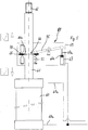
- Fig. 1 shows a possible basic structure of a movement device 1 according to the invention, as it may be provided in connection with a vertically movable up and down load.
- the load is a guided in not shown rails lifting door, which can be moved to open and close a door opening up and down.
- the embodiment of Fig. 1 it is not limited to lifting doors, it can be used in principle together with any movable load, in which it is possible to arrange along the intended direction of movement of the load extending guide element 3.
- both the load and the securing element is vertically movable up and down, in other embodiments of the invention may also be provided deviating movement directions.
- guide elements can also be provided with an orientation which does not run parallel to the intended direction of movement of the load.
- the guide element 3 is formed as a longitudinally extended in the vertical direction and thus extending parallel to the intended direction of movement rod.
- the cross section of the rod provided as a guide element 3 is in the case of the embodiment of Fig. 1 a circular cross-section 4 ( Fig. 1 b) ,
- other symmetrical or asymmetrical cross-sectional shapes may be provided for the guide element 3 instead of a circular cross-section 4.
- the guide element 3 along the intended movement of a securing element with respect to size and shape constant cross-sectional shape.
- the securing element discussed in more detail below is guided on, or relative to, the guide element 3.
- the load namely, here the lifting door, also guided with respect to their movement on the guide element 3.
- the securing element and the load may each have their own guide elements, which are each associated only with the load or only the securing element.
- a ring with its circular recess 6 is pushed onto the guide element in the illustrated embodiment, ie a recess 6 whose geometric cross-sectional shape corresponds to the cross-sectional shape of the guide element 3.
- the size of the surface of the recess 6 differs from the size of the cross-sectional area of the guide element 3.
- the surface of the recess 6 is larger than the cross-sectional area 4.
- the securing element 5 is part of a movement device 1 belonging to the securing device 8, which has a housing 9.
- the housing 9 of the securing device 8 has the function of a support for receiving components of the securing device and is provided for longitudinal movement along the fixed guide element 3 as a function of the movement of the load, here the Hubee.
- the housing 9 can therefore be arranged on the Hubte and thus moves together with the Hubee.
- the securing element 5 is arranged within the housing 9 and here tiltably mounted at a point 10 of its ring by means of suitable bearing means 11.
- the force of a spring 13 acts on the securing element 5 a.
- the spring force is at least substantially parallel aligned with the intended direction of movement and acts against one of the annular surfaces 5a, 5b, here against the bottom 5a. Also substantially diametrically opposite the bearing point 10 acts from the load to be moved at least indirectly derived process force on the ring.
- the process force can be derived from one of the weight of the load completely or at least only partially corresponding weight of a counterweight 2 to the weight of the lifting door, which is transmitted to the securing device 8 via a cable or chain 14 or other stop means.
- the counterweight or balance weight 2 to be applied to the movement of the lifting door force or the force that moves the lower at a lowering of the lift door down, at least reduced or even at least approximately canceled.
- This arrangement may be provided except for lifting doors in any other arbitrary load in which one or more loads to be secured against their weight and / or moved.
- the weight of the counterweight 2 acts on a pivotally mounted lever 16, which in turn presses on the ring 5.
- the applied by the lever 16 to the ring process force acts with respect to the Einwirkstelle the spring 13, on the other side of the ring on the latter.
- the ring is brought into its release position or neutral position, in which the ring 5 has no contact with the guide element.
- the movement of the lever 16 or the securing element 5 is limited, for example, by means of a stop with which the movement of the ring 5 is stopped due to the process force transmitted to it at a certain position of the ring, in particular independently of the process force still acting on the ring.
- this position can advantageously be the neutral position in which the longitudinal axis 3b of the recess runs coaxially with the longitudinal axis 3b of the guide element 3 and thus the boundary surface of the recess has no contact with the guide element.
- the process force counteracts in particular the spring force of the spring 13.
- any other means may be provided instead of a spring 13 be with which a biasing force for the fuse element can be generated and exercised.
- the size of the spring force and the possible spring travel are chosen so that it moves at a greatly reduced, especially in the absence of acting on the securing element 5, process force, the fuse element from its neutral position.
- This caused by the spring 13 movement is in the exemplary embodiment, a tilting movement of the securing element 5 about its bearing point 10, through which the securing element is made obliquely with respect to the longitudinal axis 3b of the guide element 3 and on two opposite sides of the guide element in abutment against the guide element. 3 arrives.
- the process force can be changed mainly by the chain or the rope (stopper) 14 breaks, to which the load and the counterweight 2 is attached, as shown schematically in FIG Fig. 2a is shown. It is also conceivable that the counterweight sits on an obstacle or strikes against such and thus can no longer act with its full weight on the securing device 8. If the weight of the counterweight 2 wholly or partially fails, so there is a preponderance of the spring force on the fuse element and this leads to a tilting or pivoting movement of the securing element 5. In the illustrated embodiment, a tilting movement takes place around the bearing point 10, wherein in the illustration of Fig. 2a the tilting axis is aligned perpendicular to the plane of the drawing.
- the annular securing element 5 comes with points of its boundary surface 6a of the recess 6 against locations of the peripheral surface 3a of the guide element 3.
- One of these points is located in the region of the bearing point 10, the other point is in the region of contact of the spring 13 with the securing element 5.
- the fuse element 5 Due to the tilted with respect to the longitudinal axis of the guide member 3 and its original position arrangement, the fuse element 5 is applied a location of its peripheral surface, especially with a region of the lower edge of the boundary surface 6a and on the especially with a region of the upper edge of the boundary surface 6a of the recess 6 at.
- the securing element 5 is tilted against the guide element 3 and immediately after the omission or sufficiently large reduction of the process force makes longitudinal movement of the securing element 5 and thus also of the housing 9 parallel to the longitudinal course of the guide element 3 impossible. Since the housing 9 of the securing device is attached to the lifting door, the lifting door is stopped.
- Fig. 3a, 3b is a pneumatic or hydraulic drive 30 shown with the moving piston 31 exercised a function and / or a load not shown in detail can be moved.
- the housing 39 of a further embodiment of a securing device 38 according to the invention is also attached.
- the securing device 38 may, except for the manner of initiation of the process force according to the embodiment of Fig. 1 be educated.
- Fig. 3 is used as a process force or load derived from the pressure means of the cylinder 32 force, which is also introduced to the movement of the piston 31 in the pressure cylinder 32.
- a single-acting further cylinder 37 is provided.
- the piston 37a Due to the pressure load of the piston 37a with the pressure medium, the piston 37a is extended to a certain position out of the cylinder 37. In this position, the piston 37a is pressure-loaded with a certain force and thereby presses on a pivotally mounted lever 45 on one side of the securing element 35. Again, the force acting on the securing element 35 by the process force is determined so that it counteracts the spring force set acting spring 43 cancels and transfers the retaining ring against the spring force in the neutral position or holds in this. As shown by Fig. 3a The lever 45 generates a torque about the bearing 40. By a stop, not shown, either for the locking ring or the lever, a movement of the ring is stopped in its neutral position.
- Fig. 4a is the moving device off Fig. 3a shown in a state in which an unexpected pressure drop occurs in the cylinder 32 and in the pressure medium supply.
- the spring 43 pushes the securing element 35 into a position tilted about the bearing point 40, in which points of edge regions of the boundary surfaces 36a abut against the guide element 33.
- the tilting of the boundary wall 36a of the recess 36 with the lateral surface of the guide member 33 abruptly stops the longitudinal movement of the fuse element 35 and thus also the housing 39 of the securing device.
- FIG. 5 . 6 an embodiment of a movement device according to the invention with a securing device is shown, in which the securing device is in turn arranged on a guide element.
- the moving device is similar to that of the Fig. 4a and 4b educated.
- the following is therefore mainly due to the differences from the embodiment according to the invention according to the Fig. 4a and 4b received.
- the essential difference is that in the embodiment according to the invention according to the Figures 5 and 6 as a guide element, an element is used, with the same time the drive movement for the load is generated.
- This operating principle is independent of the application specifically shown here with a pressure cylinder and the concrete design of the securing device provided here and can also be used together with other drive types.
- the pressure cylinder 60 When using the movement device, the pressure cylinder 60 is supplied via the pressure line 60a with a pressure medium. Due to the variable pressure, a position of the piston or its piston rod 61 can be changed in its axial direction. In an unforeseen pressure drop due to the common pressure medium supply this pressure drop also takes place in the pressure cylinder 67 of the securing device 68. The pressure drop thus leads to an uncontrolled retraction movement of the piston 61 into the pressure cylinder 60. If necessary, the load driven by the pressure cylinder 60 may no longer be moved or held as intended and cause damage and injury even by uncontrolled movements.
- the process force provided by the force of the piston 67a of the cylinder 67 is at least reduced or it falls completely off.
- the piston 67a can be retracted into the cylinder 67 and the lever 75 pivoted due to the force of a spring 67b.
- the at least reduced force (or torque) now exerted by the piston 67a results in at least a lower load on the securing element 65 by the lever 75 or in a complete cancellation of the load on the securing element 65 caused by the lever 75
- Lever 75 still presses against the securing element 65
- the force of the lever 75 counteracting spring force causes the Power of the lever 75 is neutralized
- the securing member moves from its neutral position and is brought into abutment against the guide member due to a pivoting or tilting movement about its bearing point 70.
- the ring 65 is thereby released by the lever 75 and arranged on the piston rod 61 securing device is thereby triggered.
- the securing element 65 is thus transferred from its neutral position to its tilted position, in which the securing element is clamped against the guide element and thereby the housing 69 or carrier of the securing device on the guide element, here the piston rod 61, locked and blocked.
Landscapes
- Engineering & Computer Science (AREA)
- Mechanical Engineering (AREA)
- Operating, Guiding And Securing Of Roll- Type Closing Members (AREA)
- Manipulator (AREA)
Applications Claiming Priority (1)
| Application Number | Priority Date | Filing Date | Title |
|---|---|---|---|
| DE102015016351.5A DE102015016351A1 (de) | 2015-12-17 | 2015-12-17 | Sicherheitseinrichtung zur Vermeidung unkotrollierter Bewegungen von Lasten |
Publications (2)
| Publication Number | Publication Date |
|---|---|
| EP3181507A2 true EP3181507A2 (fr) | 2017-06-21 |
| EP3181507A3 EP3181507A3 (fr) | 2017-07-05 |
Family
ID=57867966
Family Applications (1)
| Application Number | Title | Priority Date | Filing Date |
|---|---|---|---|
| EP16002679.5A Pending EP3181507A3 (fr) | 2015-12-17 | 2016-12-16 | Dispositif de sécurité pour éviter les mouvements incontrôlés de charges |
Country Status (2)
| Country | Link |
|---|---|
| EP (1) | EP3181507A3 (fr) |
| DE (1) | DE102015016351A1 (fr) |
Cited By (1)
| Publication number | Priority date | Publication date | Assignee | Title |
|---|---|---|---|---|
| CN118619109A (zh) * | 2024-08-14 | 2024-09-10 | 邹平天晟金属科技有限公司 | 一种压铸模具辅助吊装设备 |
Citations (2)
| Publication number | Priority date | Publication date | Assignee | Title |
|---|---|---|---|---|
| US4072254A (en) * | 1976-07-07 | 1978-02-07 | P.C. Cox (Mastic Appliances) Limited | Dispensing guns |
| DE3814275A1 (de) * | 1987-04-28 | 1988-12-01 | Novoferm Stahlbauwerk Neumayer | Fallbremse |
Family Cites Families (5)
| Publication number | Priority date | Publication date | Assignee | Title |
|---|---|---|---|---|
| DE1406200A1 (de) * | 1962-08-16 | 1968-10-03 | Loedige Alois Dipl Ing | Feinstregel-Fangbremse |
| FR2319571A1 (fr) * | 1975-07-30 | 1977-02-25 | Tractel Sa | Dispositif anti-chute automatique a rupture de charge |
| DE4313335C2 (de) * | 1993-04-23 | 1997-01-09 | Matthias Schum | Schlitten mit Fallbremse |
| JPH08282806A (ja) * | 1995-04-14 | 1996-10-29 | Toyota Autom Loom Works Ltd | 自動倉庫用スタッカクレーン |
| CN1235791C (zh) * | 2001-01-18 | 2006-01-11 | 普卢姆塔茨有限公司 | 用于电梯或悬荷的紧急制动和减震装置 |
-
2015
- 2015-12-17 DE DE102015016351.5A patent/DE102015016351A1/de active Pending
-
2016
- 2016-12-16 EP EP16002679.5A patent/EP3181507A3/fr active Pending
Patent Citations (2)
| Publication number | Priority date | Publication date | Assignee | Title |
|---|---|---|---|---|
| US4072254A (en) * | 1976-07-07 | 1978-02-07 | P.C. Cox (Mastic Appliances) Limited | Dispensing guns |
| DE3814275A1 (de) * | 1987-04-28 | 1988-12-01 | Novoferm Stahlbauwerk Neumayer | Fallbremse |
Cited By (1)
| Publication number | Priority date | Publication date | Assignee | Title |
|---|---|---|---|---|
| CN118619109A (zh) * | 2024-08-14 | 2024-09-10 | 邹平天晟金属科技有限公司 | 一种压铸模具辅助吊装设备 |
Also Published As
| Publication number | Publication date |
|---|---|
| DE102015016351A1 (de) | 2017-08-10 |
| EP3181507A3 (fr) | 2017-07-05 |
Similar Documents
| Publication | Publication Date | Title |
|---|---|---|
| EP3526427B1 (fr) | Dispositif de sécurité anti-chute pour les personnes | |
| DE102004010987B4 (de) | Sicherungseinheit | |
| EP3538468B1 (fr) | Frein à câble, cabine d'ascenseur et ascenseur | |
| EP4026962B1 (fr) | Supports de coffrage, dispositif de support de coffrage et procédé de décoffrage d'un agencement de coffrage | |
| EP3468908B1 (fr) | Dispositif de levage avec dispositif d'arrêt | |
| EP2019076A1 (fr) | Table élévatrice à pietements articulés | |
| EP3470355A1 (fr) | Dispositif tampon pour une cabine d'ascenseur ainsi qu'agencement du dispositif tampon et ascenseur | |
| WO2021122385A1 (fr) | Frein de sécurité pour un ascenseur | |
| EP4359256B1 (fr) | Dispositif de verrouillage de conteneur et procédé de verrouillage de conteneur | |
| EP3748112B1 (fr) | Protection contre les chutes pour une porte relevable, en particulier porte relevable de protection de machine | |
| EP3181507A2 (fr) | Dispositif de sécurité pour éviter les mouvements incontrôlés de charges | |
| EP2706032B1 (fr) | Dispositif de réception de charge, en particulier moufle inférieure pour un appareil de levage | |
| EP2310151B1 (fr) | Laminoir comportant un dispositif de déplacement | |
| EP0568858B1 (fr) | Dispositif de verrouillage d'un piston commandé par pression, en particulier pour la commande d'une barre antirenversement d'un véhicule | |
| EP2848854B1 (fr) | Dispositif de blocage d'un élément de construction mobile | |
| DE102018105102A1 (de) | Fangzylinder sowie Lasthebemittel mit einem Fangzylinder | |
| DE69304940T2 (de) | Selbsttätig schliessendes Bodentor | |
| WO2018091294A1 (fr) | Installation d'extraction par puits pourvue de dispositif de freinage d'envoi aux molettes | |
| WO2007065488A1 (fr) | Dispositif et procede pour le declenchement d'un dispositif antichute | |
| DE202019102262U1 (de) | Abschaltpuffer für ein Hebezeug, insbesondere Kettenzug, und Hebezeug hiermit | |
| EP3666719A1 (fr) | Dispositif automatique de blocage anti-déroulement | |
| EP1957739B1 (fr) | Dispositif de protection d'arête | |
| EP3277554B1 (fr) | Accumulateur d'énergie pour siège de télésiège | |
| DE29519425U1 (de) | Hubvorrichtung für Fahrzeuge | |
| DE102010045931B4 (de) | Doppeltes mechanisches Bremselement für Linearführungen |
Legal Events
| Date | Code | Title | Description |
|---|---|---|---|
| PUAI | Public reference made under article 153(3) epc to a published international application that has entered the european phase |
Free format text: ORIGINAL CODE: 0009012 |
|
| STAA | Information on the status of an ep patent application or granted ep patent |
Free format text: STATUS: THE APPLICATION HAS BEEN PUBLISHED |
|
| PUAL | Search report despatched |
Free format text: ORIGINAL CODE: 0009013 |
|
| AK | Designated contracting states |
Kind code of ref document: A2 Designated state(s): AL AT BE BG CH CY CZ DE DK EE ES FI FR GB GR HR HU IE IS IT LI LT LU LV MC MK MT NL NO PL PT RO RS SE SI SK SM TR |
|
| AX | Request for extension of the european patent |
Extension state: BA ME |
|
| AK | Designated contracting states |
Kind code of ref document: A3 Designated state(s): AL AT BE BG CH CY CZ DE DK EE ES FI FR GB GR HR HU IE IS IT LI LT LU LV MC MK MT NL NO PL PT RO RS SE SI SK SM TR |
|
| AX | Request for extension of the european patent |
Extension state: BA ME |
|
| RIC1 | Information provided on ipc code assigned before grant |
Ipc: B66B 5/18 20060101ALI20170531BHEP Ipc: B66B 5/12 20060101ALI20170531BHEP Ipc: B66C 15/02 20060101ALI20170531BHEP Ipc: B66D 5/16 20060101ALI20170531BHEP Ipc: B66C 15/00 20060101AFI20170531BHEP |
|
| STAA | Information on the status of an ep patent application or granted ep patent |
Free format text: STATUS: REQUEST FOR EXAMINATION WAS MADE |
|
| 17P | Request for examination filed |
Effective date: 20171229 |
|
| RBV | Designated contracting states (corrected) |
Designated state(s): AL AT BE BG CH CY CZ DE DK EE ES FI FR GB GR HR HU IE IS IT LI LT LU LV MC MK MT NL NO PL PT RO RS SE SI SK SM TR |
|
| R17P | Request for examination filed (corrected) |
Effective date: 20171229 |
|
| RIN1 | Information on inventor provided before grant (corrected) |
Inventor name: RISCH, KARL HEINZ Inventor name: BOEHNLEIN, ANDREAS |
|
| STAA | Information on the status of an ep patent application or granted ep patent |
Free format text: STATUS: EXAMINATION IS IN PROGRESS |
|
| 17Q | First examination report despatched |
Effective date: 20210702 |