EP3748112B1 - Protection contre les chutes pour une porte relevable, en particulier porte relevable de protection de machine - Google Patents
Protection contre les chutes pour une porte relevable, en particulier porte relevable de protection de machine Download PDFInfo
- Publication number
- EP3748112B1 EP3748112B1 EP20175158.3A EP20175158A EP3748112B1 EP 3748112 B1 EP3748112 B1 EP 3748112B1 EP 20175158 A EP20175158 A EP 20175158A EP 3748112 B1 EP3748112 B1 EP 3748112B1
- Authority
- EP
- European Patent Office
- Prior art keywords
- gate
- carrier
- stop element
- stop
- latch
- Prior art date
- Legal status (The legal status is an assumption and is not a legal conclusion. Google has not performed a legal analysis and makes no representation as to the accuracy of the status listed.)
- Active
Links
Images




Classifications
-
- E—FIXED CONSTRUCTIONS
- E05—LOCKS; KEYS; WINDOW OR DOOR FITTINGS; SAFES
- E05D—HINGES OR SUSPENSION DEVICES FOR DOORS, WINDOWS OR WINGS
- E05D13/00—Accessories for sliding or lifting wings, e.g. pulleys, safety catches
- E05D13/003—Anti-dropping devices
- E05D13/006—Anti-dropping devices fixed to the wing, i.e. safety catches
-
- E—FIXED CONSTRUCTIONS
- E06—DOORS, WINDOWS, SHUTTERS, OR ROLLER BLINDS IN GENERAL; LADDERS
- E06B—FIXED OR MOVABLE CLOSURES FOR OPENINGS IN BUILDINGS, VEHICLES, FENCES OR LIKE ENCLOSURES IN GENERAL, e.g. DOORS, WINDOWS, BLINDS, GATES
- E06B9/00—Screening or protective devices for wall or similar openings, with or without operating or securing mechanisms; Closures of similar construction
- E06B9/56—Operating, guiding or securing devices or arrangements for roll-type closures; Spring drums; Tape drums; Counterweighting arrangements therefor
- E06B9/80—Safety measures against dropping or unauthorised opening; Braking or immobilising devices; Devices for limiting unrolling
- E06B9/82—Safety measures against dropping or unauthorised opening; Braking or immobilising devices; Devices for limiting unrolling automatic
- E06B9/84—Safety measures against dropping or unauthorised opening; Braking or immobilising devices; Devices for limiting unrolling automatic against dropping
-
- E—FIXED CONSTRUCTIONS
- E05—LOCKS; KEYS; WINDOW OR DOOR FITTINGS; SAFES
- E05Y—INDEXING SCHEME ASSOCIATED WITH SUBCLASSES E05D AND E05F, RELATING TO CONSTRUCTION ELEMENTS, ELECTRIC CONTROL, POWER SUPPLY, POWER SIGNAL OR TRANSMISSION, USER INTERFACES, MOUNTING OR COUPLING, DETAILS, ACCESSORIES, AUXILIARY OPERATIONS NOT OTHERWISE PROVIDED FOR, APPLICATION THEREOF
- E05Y2999/00—Subject-matter not otherwise provided for in this subclass
Definitions
- the present invention relates to fall protection for a lifting gate, in particular a machine protection lifting gate, and a lifting gate, in particular a machine protection lifting gate, with such a fall protection.
- Elevating gates of which the present invention is particularly concerned, are used in industry as part of a safety fencing around a work area, such as a robotic work station, to provide access to the otherwise fenced work area.
- a lifting gate can also be part of an intermediate subdivision of such a work area and must be moved up and down frequently and quickly, particularly in this application.
- a fall protection for the overhead door is provided for this purpose, which mechanically locks the overhead door against downward movement by providing a pneumatically or hydraulically actuated bolt that can be brought into a bolt-eyelet connection.
- the latch is actively actuated to bring it into its locked position within the eyelet.
- the bolt is actuated in order to remove it from the eyelet and thus release the mechanical locking. Due to the active control, conventional fall protection systems are complex and require a lot of maintenance.
- EP 0 721 043 A1 discloses a monitoring device for a support cable of a door leaf with an electric catch device connected to the support cable and a mechanical catch device which are connected in series in such a way that first the electric catch device and then the mechanical catch device responds.
- JPH0740994 U discloses a locking device for preventing vertical movement of the roller shutter in an upward direction, which comprises an end slat movable in a vertical direction for joint movement with the roller shutter and a support element which is stationary in the vertical direction and which can be brought into a mechanically locked engagement blocking vertical movement of the end slat ; wherein the locking device also has at least one pawl which is connected at least indirectly to the end lamella in an articulated manner and which can be pivoted into mechanically locking engagement with the support element, and a stop element is mounted in a resilient manner on the end lamella, the end lamella having a pin in which the pawl is guided in that it is pivoted in the direction of the support element when the stop element deflects, with the stop element being assigned a stop in a predetermined vertical end position, against which the stop element strikes during a vertical movement of the end plate.
- the present invention is based on the object of specifying a fall protection for a lifting gate, wherein the fall protection does not require an active control, can be produced inexpensively, is advantageously low-maintenance or maintenance-free and works reliably.
- a fall protection according to the invention for a lifting gate in particular a machine protection lifting gate of the type explained at the outset, has at least one mechanical locking device which comprises a gate carrier that can be moved in a vertical direction for joint movement with the lifting gate and a support element that is stationary in the vertical direction, with the gate carrier and the support element in a mechanically locked engagement blocking a vertical movement, in particular a downward movement, of the gate carrier.
- the locking device comprises at least one pawl which is connected at least indirectly to the door carrier in an articulated manner and which can be pivoted into the mechanically locked engagement with the support element.
- a stop element is mounted in a resilient manner on the gate carrier, which has a guide in which the pawl is guided in such a way that, when the Stop element is pivoted in the direction of the support element.
- the stop element In a predetermined vertical end position, in particular in a predetermined upper position, the stop element is assigned a stop against which the stop element strikes during a vertical movement, in particular an upward movement, of the gate carrier.
- the fall protection is provided at the upper end of the lifting gate in order to prevent an undesired movement of the gate carrier and thus of the lifting gate in a vertical downward movement.
- it can also be used at a lower end of the lifting gate to prevent a vertical movement of the gate carrier or the lifting gate in an upward direction when a robot arm strikes from below.
- the anti-fall device prevents the gate carrier or lifting gate from moving downwards.
- the support element includes a bolt and the pawl includes a mouth, wherein the mouth can be hung on the bolt by pivoting the pawl.
- the support element comprises a corresponding mouth or a recess and the pawl has a bolt which can be hung in the mouth or the recess.
- Other embodiments are possible.
- the guide includes a link with which a link block connected to the pawl is in engagement.
- the pawl is rotatably connected at least indirectly to the door support about a horizontal axis of rotation.
- a pivoting movement can also be considered, in which the pawl executes a combined rotating and sliding movement.
- the stop is mounted so that it can be displaced in the vertical direction against a spring force. In this way, tolerances when approaching the end position of the gate carrier or the lifting gate can be compensated for if, for example, a drive device does not move the lifting gate exactly into the desired end position.
- the stop element In order to safely intercept an impact of a robot arm from above on the gate carrier without the risk of the gate carrier being released from its mechanical locking with the support element, the stop element preferably completely covers the gate carrier on its upper side. In the case of protection against the gate carrier being displaced upwards, the stop element would preferably completely cover the underside of the gate carrier.
- the stop element can be mounted on the gate carrier, for example, by means of at least one compression spring or with a multiplicity of compression springs.
- a lifting gate according to the invention has at least one gate field and at least one drive device for moving the gate field up and down in a vertical direction.
- the goal field is connected to the goal support of a fall protection device according to the invention.
- the goal carrier is formed by the goal field itself.
- the goal field can have several segments that can be moved one behind the other. Each segment that is comparatively lower is advantageously positioned on the side of the goal field above it that faces away from the work area or danger area in which, for example, a robot is standing, in order to prevent, for example, a robot arm from above falling onto a segment that is not covered by the stop element beats. As a rule, it can be sufficient to secure only the top goal area with a fall protection device according to the invention.
- the drive device is advantageously connected vertically below the stop element and separately from the stop element on the door panel and/or on the door carrier.
- the drive device can, for example, comprise a chain drive or a belt drive, which is connected to the door field and/or to the door carrier.
- a chain drive or a belt drive which is connected to the door field and/or to the door carrier.
- other drive devices can also be considered.
- the fall protection according to the invention advantageously does not require an external control and advantageously works purely mechanically.
- Various springs that work together are advantageously matched to one another in terms of spring force. If, for example, the stop is slidably mounted against the force of at least one spring, this spring or spring combination has in particular a greater spring force than the spring or spring combination with which the stop element is supported on the door carrier.
- the spring force of the spring/spring combination assigned to the stop is twice the spring force that is made available by the at least one spring or spring combination with which the stop element is mounted on the door carrier.
- the stop itself can be designed, for example, in the form of a rubber buffer.
- the stop element strikes the stop first and is moved relative to the gate support as the gate support continues to be moved.
- the pawl connected to the gate carrier is pivoted due to the guide provided on the stop element, so that it moves in the direction of the support element for its mechanical locking and is finally locked with the support element.
- a body for example a robot arm
- strikes the stop element from above a force is thereby exerted on the stop element, which pushes it in the direction of the gate carrier.
- a further or increasing locking force is exerted on the pawl, which pushes it in the direction of the support element. A movement of the pawl out of the mechanical locking with the support element is reliably avoided.
- a drive force of the drive device acts on the lifting door or the door support, in the sense of a vertical movement, in particular downward movement, of the lifting door or door support
- the door support is removed from the stop element, which initially presses against the stop with the spring force of the spring/spring combination between the door support and the stop element is depressed and remains there, and the guide pivots the latch back out of its locking engagement with the support member.
- the mechanical locking between the pawl and the support element is canceled and the gate carrier or the lifting gate can be moved, in particular downwards, as desired.
- a spring-loaded stop allows the gate support or the lifting gate to move by a predetermined further distance in the direction of the stop, even if the stop element has already hit the stop and has moved relatively in the direction of the gate carrier so that the pawl locks with the support element can be, because then the stop yields elastically due to its resilient suspension.
- this does not disturb the secure locking between the pawl and the support element and damage to the drive device, for example a chain drive or belt drive, is prevented.
- the risk of the stop element or the stop being damaged is also minimized.
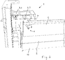
- a fall protection according to the invention with a mechanical locking device 1 is shown, which comprises a gate carrier 2 that can be moved in a vertical direction Z and a support element 3 that is stationary in the vertical direction Z.
- the gate carrier 2 can be brought into a mechanically locked engagement with the support element 3 .
- the locking device 1 also includes a pawl 4 which is connected to the gate carrier 2 and which can be pivoted into the mechanically locked engagement with the support element 3 .
- the pawl 4 comprises a bolt 4.2 which can be hooked into a mouth 3.2 or a recess in the support element 3.
- a stop element 5 is resiliently mounted on the gate support 2 and has a guide 6 in which the pawl 4 is guided in such a way that it is pivoted in the direction of the support element 3 when the stop element 5 is compressed in the direction of the gate support 2 .
- the guide 6 comprises a connecting link 6.1, with which a sliding block 8 connected to the pawl 4 engages in order to force the pivoting movement of the pawl 4 when the stop element 5 is moved towards the door carrier 2.
- the gate carrier 2 is mounted slidably in two lateral gate guides 13, which is located in the Extend in the vertical direction Z.
- a stop 7 is provided at the upper end of the lateral door guides 13, against which the stop element 5 strikes when the lifting door 10 or the door carrier 2 moves into its upper end position.
- the stop element 5 first hits the stop 7 and is thereby stopped in its movement in the vertical direction Z, whereas the door carrier 2, which is driven, is moved further up in the vertical direction Z.
- the stop element 5 springs against the force of the at least one compression spring 9, with which it is mounted on the gate carrier 2, in the direction of the gate carrier 2.
- link 6.1 forces link block 8 outwards in a direction transverse to vertical direction Z.
- the pawl 4 is pivoted outwards in the direction of the support element 3 and is brought with its bolt 4.2 into an area above the mouth 3.2 in the support element 3 or is inserted directly into the mouth 3.2.
- the drive device not shown here is switched off and the lifting gate 10 or the gate carrier 2 is in its upper end position.
- the lifting gate 10 or the gate carrier 2 is held in the upper end position by the drive device because the drive device has a corresponding self-locking mechanism.
- this self-locking is not large enough to support a comparatively large downward force that is exerted on the lifting gate 10 .
- Such a comparatively large force can be exerted, for example, by a robot arm hitting the gate carrier 2 or the stop element 5 from above, and without the fall protection, the lifting gate 10 would be knocked down.
- a drive device acts on the gate carrier 2 and exerts a downward force on it in the vertical direction Z
- the gate carrier 2 moves downwards and the compression spring 9 springs out, as a result of which the stop element 5 is initially still held on the stop 7, so that the Gate carrier 2 removed from stop element 5.
- This moves the sliding block 8 in the link 6.1 inwards and the pawl 4 is removed from its position with the bolt 4.2 above or in the mouth 3.2 and pivoted inwards, so that the gate carrier 2 then moves downwards together with the stop element 5 can be.
- the pawl 4 is connected to the gate carrier 2 in an articulated manner about the axis of rotation Y, so that it executes a pure rotational movement.
- another bearing could also be provided.
- the stop 7 is formed by a component that is resiliently mounted in the vertical direction Z, here a rubber buffer. If the stop element 5 strikes the stop 7 and is then deflected against the compression spring 9, the stop compression spring 7.1 allows the stop 7 to yield or be displaced in the vertical direction Z, in order to avoid damage, if a drive device moves the door carrier 2 further upwards to prevent the drive device or the mechanical locking device 1.
- the stop compression spring 7.1 has a greater spring force than the compression spring 9 in order to ensure that the compression spring 9 compresses first before the compression stop spring 7.1 compresses.
- a lifting gate 10 is shown as an example, which comprises, for example, several gate fields 11 that can be pushed one behind the other.
- a drive device 12 for example in the form of a belt drive or chain drive, acts on the lifting gate 10.
- Components of the mechanical locking device 1 are also shown as examples.
Landscapes
- Engineering & Computer Science (AREA)
- Structural Engineering (AREA)
- Architecture (AREA)
- Civil Engineering (AREA)
- Mechanical Engineering (AREA)
- Refuge Islands, Traffic Blockers, Or Guard Fence (AREA)
- Devices For Checking Fares Or Tickets At Control Points (AREA)
- Forklifts And Lifting Vehicles (AREA)
- Jib Cranes (AREA)
- Power-Operated Mechanisms For Wings (AREA)
Claims (11)
- Sécurité antichute pour une porte relevable (10), en particulier une porte relevable pour la protection d'une machine, avec un dispositif de verrouillage mécanique (1) qui comporte un support de porte (2) mobile dans un sens vertical (Z) pour se déplacer en même temps que la porte relevable (10) et un élément d'appui (3) fixe dans le sens vertical (Z), qui peuvent se mettre en prise l'un dans l'autre pour réaliser un verrouillage mécanique et bloquer le mouvement vertical du support de porte (2), dans laquelle le dispositif de verrouillage (1) comporte en outre au moins une targette (4) reliée au moins indirectement au support de porte (2), qui peut basculer en prise avec l'élément de support (3) pour réaliser le verrouillage mécanique, et un élément de butée (5) est supporté sur le support de porte (2) avec possibilité de recul élastique et possède un guide (6) dans lequel la targette (4) est guidée de telle façon que, lors d'un recul élastique de l'élément de butée (5), elle pivote en direction de l'élément d'appui (3), l'élément de butée (5) étant associé, dans sa position de fin de course verticale définie, à une butée (7) sur laquelle l'élément de butée (5) bute lors d'un déplacement vertical du support de porte (2).
- Sécurité antichute selon la revendication 1, caractérisée en ce que l'élément d'appui (3) comporte un boulon (3.1) et la targette (4) comporte un mors (4.1) qui peut être accroché sur le boulon (3.1) par le pivotement de la targette (4).
- Sécurité antichute selon la revendication 1, caractérisée en ce que l'élément d'appui (3) comporte un mors (3.2) ou une découpe et la targette (4) comporte un boulon (4.2) qui peut être accroché dans le mors (3.2) par le pivotement de la targette (4).
- Sécurité antichute selon l'une des revendications 1 à 3, caractérisée en ce que le guide (6) comporte une coulisse (6.1) avec laquelle un coulisseau (8) relié à la targette (4) est en prise.
- Sécurité antichute selon l'une des revendications 1 à 4, caractérisée en ce que la targette (4) est raccordée au moins indirectement au support de porte (2) avec possibilité de rotation autour d'un axe de rotation horizontal (Y).
- Sécurité antichute selon l'une des revendications 1 à 5, caractérisée en ce que la butée (7) est supportée avec possibilité de translation dans le sens vertical (Z) contre une force de ressort.
- Sécurité antichute selon l'une des revendications 1 à 6, caractérisée en ce que l'élément de butée (5) recouvre complètement le support de porte (2) sur sa face supérieure.
- Sécurité antichute selon l'une des revendications 1 à 7, caractérisée en ce que l'élément de butée (5) est supporté sur le support de porte (2) au moyen d'au moins un ressort de compression (9), en particulier de plusieurs ressorts de compression (9).
- Porte relevable (10) avec au moins un tablier de porte (11) et un dispositif d'entraînement (12) pour lever et abaisser le tablier de porte (11) dans un sens vertical (Z), caractérisée en ce qu'elle comporte une sécurité antichute selon l'une des revendications 1 à 8, dont le support de porte (2) est relié au tablier de porte (11) ou formé par celui-ci.
- Porte relevable (10) selon la revendication 9, caractérisée en ce que le dispositif d'entraînement (12) est raccordé verticalement au tablier de porte (11) et/ou au support de porte (2) en dessous de l'élément de butée (5) et découplé de l'élément de butée (5).
- Porte relevable (10) selon l'une des revendications 9 ou 10, caractérisée en ce que le dispositif d'entraînement (12) comprend un entraînement à chaîne ou à courroie qui est relié au tablier de porte (11) et/ou au support de porte (2).
Applications Claiming Priority (1)
| Application Number | Priority Date | Filing Date | Title |
|---|---|---|---|
| DE102019208180.0A DE102019208180B3 (de) | 2019-06-05 | 2019-06-05 | Absturzsicherung für ein Hubtor, insbesondere Maschinenschutzhubtor |
Publications (2)
| Publication Number | Publication Date |
|---|---|
| EP3748112A1 EP3748112A1 (fr) | 2020-12-09 |
| EP3748112B1 true EP3748112B1 (fr) | 2022-10-19 |
Family
ID=70740487
Family Applications (1)
| Application Number | Title | Priority Date | Filing Date |
|---|---|---|---|
| EP20175158.3A Active EP3748112B1 (fr) | 2019-06-05 | 2020-05-18 | Protection contre les chutes pour une porte relevable, en particulier porte relevable de protection de machine |
Country Status (4)
| Country | Link |
|---|---|
| EP (1) | EP3748112B1 (fr) |
| DE (1) | DE102019208180B3 (fr) |
| ES (1) | ES2932617T3 (fr) |
| HU (1) | HUE060755T2 (fr) |
Families Citing this family (2)
| Publication number | Priority date | Publication date | Assignee | Title |
|---|---|---|---|---|
| US12410647B2 (en) * | 2022-10-11 | 2025-09-09 | Clopay Corporation | Door stop mechanism |
| US12392184B2 (en) * | 2022-10-11 | 2025-08-19 | Cornellcookson, Llc | Sectional door braking system |
Citations (1)
| Publication number | Priority date | Publication date | Assignee | Title |
|---|---|---|---|---|
| JPS5661693U (fr) * | 1979-10-16 | 1981-05-25 |
Family Cites Families (4)
| Publication number | Priority date | Publication date | Assignee | Title |
|---|---|---|---|---|
| DE341009C (fr) * | ||||
| DE4024666C2 (de) * | 1990-06-01 | 1994-02-03 | Niemetz Torbau Und Metallbau | Sektionaltor |
| JP2554234Y2 (ja) * | 1993-12-27 | 1997-11-17 | 三和シヤッター工業株式会社 | 建築用電動シヤツターにおける障害物検知装置 |
| DK0721043T3 (da) * | 1995-01-05 | 1999-10-25 | Marantec Antrieb Steuerung | Indretning til overvågning af et træktov af en portflade |
-
2019
- 2019-06-05 DE DE102019208180.0A patent/DE102019208180B3/de not_active Expired - Fee Related
-
2020
- 2020-05-18 EP EP20175158.3A patent/EP3748112B1/fr active Active
- 2020-05-18 ES ES20175158T patent/ES2932617T3/es active Active
- 2020-05-18 HU HUE20175158A patent/HUE060755T2/hu unknown
Patent Citations (1)
| Publication number | Priority date | Publication date | Assignee | Title |
|---|---|---|---|---|
| JPS5661693U (fr) * | 1979-10-16 | 1981-05-25 |
Also Published As
| Publication number | Publication date |
|---|---|
| HUE060755T2 (hu) | 2023-04-28 |
| ES2932617T3 (es) | 2023-01-23 |
| DE102019208180B3 (de) | 2020-08-20 |
| EP3748112A1 (fr) | 2020-12-09 |
Similar Documents
| Publication | Publication Date | Title |
|---|---|---|
| EP1541518B1 (fr) | Dispositif d'entraînement de porte pour ascenseur | |
| EP2399826B1 (fr) | Dispositif de fixation pour la fixation au moins partielle d'un premier et d'un second colis | |
| EP3417134B1 (fr) | Ensemble ferrure pour le raccordement d'un battant coulissant et basculant | |
| WO2017036795A1 (fr) | Dispositif de positionnement de deux portes coulissantes et meuble | |
| EP0151427B1 (fr) | Appareil de contrôle pour ressort d'équilibrage | |
| DE202015006895U1 (de) | Aufstellbares Klappenscharnier | |
| DE3710237A1 (de) | Fangvorrichtung fuer nach oben oeffnende tore | |
| EP3748112A1 (fr) | Protection contre les chutes pour une porte relevable, en particulier porte relevable de protection de machine | |
| DE202010005519U1 (de) | Verschluss für Weichenstellvorrichtungen | |
| DE102007032059A1 (de) | Sicherheitsverriegelungssystem für mechanische Manipulatoren | |
| EP0279929A2 (fr) | Dispositif antichute | |
| EP0556632B1 (fr) | Porte roulante horizontale | |
| EP2843169A1 (fr) | Système de support pour une porte coulissante et porte coulissante | |
| EP3106738B1 (fr) | Dispositif destine a deplacer et a arreter une porte | |
| EP2848854B1 (fr) | Dispositif de blocage d'un élément de construction mobile | |
| EP0921970B1 (fr) | Véhicule avec un système pour fixer un objet | |
| DE202015004325U1 (de) | Verriegelungseinrichtung für ein oder mehrere Bugklappen, insbesondere für Schienenfahrzeuge | |
| DE202019102262U1 (de) | Abschaltpuffer für ein Hebezeug, insbesondere Kettenzug, und Hebezeug hiermit | |
| DE9214278U1 (de) | Sicherungsvorrichtung für Tore o.dgl. | |
| EP4230892B1 (fr) | Pont d'embarquement | |
| DE10339506B4 (de) | Hubtor | |
| EP1957739B1 (fr) | Dispositif de protection d'arête | |
| DE102010009064B4 (de) | Verriegelungsanordnung | |
| EP3181507A2 (fr) | Dispositif de sécurité pour éviter les mouvements incontrôlés de charges | |
| EP1497522B1 (fr) | Porte en plusieurs sections et dispositif de guidage associe |
Legal Events
| Date | Code | Title | Description |
|---|---|---|---|
| PUAI | Public reference made under article 153(3) epc to a published international application that has entered the european phase |
Free format text: ORIGINAL CODE: 0009012 |
|
| STAA | Information on the status of an ep patent application or granted ep patent |
Free format text: STATUS: THE APPLICATION HAS BEEN PUBLISHED |
|
| AK | Designated contracting states |
Kind code of ref document: A1 Designated state(s): AL AT BE BG CH CY CZ DE DK EE ES FI FR GB GR HR HU IE IS IT LI LT LU LV MC MK MT NL NO PL PT RO RS SE SI SK SM TR |
|
| AX | Request for extension of the european patent |
Extension state: BA ME |
|
| STAA | Information on the status of an ep patent application or granted ep patent |
Free format text: STATUS: REQUEST FOR EXAMINATION WAS MADE |
|
| 17P | Request for examination filed |
Effective date: 20210126 |
|
| RBV | Designated contracting states (corrected) |
Designated state(s): AL AT BE BG CH CY CZ DE DK EE ES FI FR GB GR HR HU IE IS IT LI LT LU LV MC MK MT NL NO PL PT RO RS SE SI SK SM TR |
|
| GRAP | Despatch of communication of intention to grant a patent |
Free format text: ORIGINAL CODE: EPIDOSNIGR1 |
|
| STAA | Information on the status of an ep patent application or granted ep patent |
Free format text: STATUS: GRANT OF PATENT IS INTENDED |
|
| INTG | Intention to grant announced |
Effective date: 20220111 |
|
| GRAJ | Information related to disapproval of communication of intention to grant by the applicant or resumption of examination proceedings by the epo deleted |
Free format text: ORIGINAL CODE: EPIDOSDIGR1 |
|
| STAA | Information on the status of an ep patent application or granted ep patent |
Free format text: STATUS: REQUEST FOR EXAMINATION WAS MADE |
|
| GRAP | Despatch of communication of intention to grant a patent |
Free format text: ORIGINAL CODE: EPIDOSNIGR1 |
|
| STAA | Information on the status of an ep patent application or granted ep patent |
Free format text: STATUS: GRANT OF PATENT IS INTENDED |
|
| INTC | Intention to grant announced (deleted) | ||
| INTG | Intention to grant announced |
Effective date: 20220506 |
|
| GRAS | Grant fee paid |
Free format text: ORIGINAL CODE: EPIDOSNIGR3 |
|
| GRAA | (expected) grant |
Free format text: ORIGINAL CODE: 0009210 |
|
| STAA | Information on the status of an ep patent application or granted ep patent |
Free format text: STATUS: THE PATENT HAS BEEN GRANTED |
|
| AK | Designated contracting states |
Kind code of ref document: B1 Designated state(s): AL AT BE BG CH CY CZ DE DK EE ES FI FR GB GR HR HU IE IS IT LI LT LU LV MC MK MT NL NO PL PT RO RS SE SI SK SM TR |
|
| REG | Reference to a national code |
Ref country code: GB Ref legal event code: FG4D Free format text: NOT ENGLISH |
|
| REG | Reference to a national code |
Ref country code: CH Ref legal event code: EP |
|
| REG | Reference to a national code |
Ref country code: DE Ref legal event code: R096 Ref document number: 502020001854 Country of ref document: DE |
|
| REG | Reference to a national code |
Ref country code: IE Ref legal event code: FG4D Free format text: LANGUAGE OF EP DOCUMENT: GERMAN |
|
| REG | Reference to a national code |
Ref country code: AT Ref legal event code: REF Ref document number: 1525639 Country of ref document: AT Kind code of ref document: T Effective date: 20221115 |
|
| REG | Reference to a national code |
Ref country code: ES Ref legal event code: FG2A Ref document number: 2932617 Country of ref document: ES Kind code of ref document: T3 Effective date: 20230123 |
|
| REG | Reference to a national code |
Ref country code: SK Ref legal event code: T3 Ref document number: E 40894 Country of ref document: SK |
|
| REG | Reference to a national code |
Ref country code: LT Ref legal event code: MG9D |
|
| REG | Reference to a national code |
Ref country code: NL Ref legal event code: MP Effective date: 20221019 |
|
| PG25 | Lapsed in a contracting state [announced via postgrant information from national office to epo] |
Ref country code: NL Free format text: LAPSE BECAUSE OF FAILURE TO SUBMIT A TRANSLATION OF THE DESCRIPTION OR TO PAY THE FEE WITHIN THE PRESCRIBED TIME-LIMIT Effective date: 20221019 |
|
| PG25 | Lapsed in a contracting state [announced via postgrant information from national office to epo] |
Ref country code: SE Free format text: LAPSE BECAUSE OF FAILURE TO SUBMIT A TRANSLATION OF THE DESCRIPTION OR TO PAY THE FEE WITHIN THE PRESCRIBED TIME-LIMIT Effective date: 20221019 Ref country code: PT Free format text: LAPSE BECAUSE OF FAILURE TO SUBMIT A TRANSLATION OF THE DESCRIPTION OR TO PAY THE FEE WITHIN THE PRESCRIBED TIME-LIMIT Effective date: 20230220 Ref country code: NO Free format text: LAPSE BECAUSE OF FAILURE TO SUBMIT A TRANSLATION OF THE DESCRIPTION OR TO PAY THE FEE WITHIN THE PRESCRIBED TIME-LIMIT Effective date: 20230119 Ref country code: LT Free format text: LAPSE BECAUSE OF FAILURE TO SUBMIT A TRANSLATION OF THE DESCRIPTION OR TO PAY THE FEE WITHIN THE PRESCRIBED TIME-LIMIT Effective date: 20221019 Ref country code: FI Free format text: LAPSE BECAUSE OF FAILURE TO SUBMIT A TRANSLATION OF THE DESCRIPTION OR TO PAY THE FEE WITHIN THE PRESCRIBED TIME-LIMIT Effective date: 20221019 |
|
| REG | Reference to a national code |
Ref country code: HU Ref legal event code: AG4A Ref document number: E060755 Country of ref document: HU |
|
| PG25 | Lapsed in a contracting state [announced via postgrant information from national office to epo] |
Ref country code: RS Free format text: LAPSE BECAUSE OF FAILURE TO SUBMIT A TRANSLATION OF THE DESCRIPTION OR TO PAY THE FEE WITHIN THE PRESCRIBED TIME-LIMIT Effective date: 20221019 Ref country code: PL Free format text: LAPSE BECAUSE OF FAILURE TO SUBMIT A TRANSLATION OF THE DESCRIPTION OR TO PAY THE FEE WITHIN THE PRESCRIBED TIME-LIMIT Effective date: 20221019 Ref country code: LV Free format text: LAPSE BECAUSE OF FAILURE TO SUBMIT A TRANSLATION OF THE DESCRIPTION OR TO PAY THE FEE WITHIN THE PRESCRIBED TIME-LIMIT Effective date: 20221019 Ref country code: IS Free format text: LAPSE BECAUSE OF FAILURE TO SUBMIT A TRANSLATION OF THE DESCRIPTION OR TO PAY THE FEE WITHIN THE PRESCRIBED TIME-LIMIT Effective date: 20230219 Ref country code: HR Free format text: LAPSE BECAUSE OF FAILURE TO SUBMIT A TRANSLATION OF THE DESCRIPTION OR TO PAY THE FEE WITHIN THE PRESCRIBED TIME-LIMIT Effective date: 20221019 Ref country code: GR Free format text: LAPSE BECAUSE OF FAILURE TO SUBMIT A TRANSLATION OF THE DESCRIPTION OR TO PAY THE FEE WITHIN THE PRESCRIBED TIME-LIMIT Effective date: 20230120 |
|
| REG | Reference to a national code |
Ref country code: DE Ref legal event code: R097 Ref document number: 502020001854 Country of ref document: DE |
|
| PG25 | Lapsed in a contracting state [announced via postgrant information from national office to epo] |
Ref country code: SM Free format text: LAPSE BECAUSE OF FAILURE TO SUBMIT A TRANSLATION OF THE DESCRIPTION OR TO PAY THE FEE WITHIN THE PRESCRIBED TIME-LIMIT Effective date: 20221019 Ref country code: RO Free format text: LAPSE BECAUSE OF FAILURE TO SUBMIT A TRANSLATION OF THE DESCRIPTION OR TO PAY THE FEE WITHIN THE PRESCRIBED TIME-LIMIT Effective date: 20221019 Ref country code: EE Free format text: LAPSE BECAUSE OF FAILURE TO SUBMIT A TRANSLATION OF THE DESCRIPTION OR TO PAY THE FEE WITHIN THE PRESCRIBED TIME-LIMIT Effective date: 20221019 Ref country code: DK Free format text: LAPSE BECAUSE OF FAILURE TO SUBMIT A TRANSLATION OF THE DESCRIPTION OR TO PAY THE FEE WITHIN THE PRESCRIBED TIME-LIMIT Effective date: 20221019 |
|
| PLBE | No opposition filed within time limit |
Free format text: ORIGINAL CODE: 0009261 |
|
| STAA | Information on the status of an ep patent application or granted ep patent |
Free format text: STATUS: NO OPPOSITION FILED WITHIN TIME LIMIT |
|
| PG25 | Lapsed in a contracting state [announced via postgrant information from national office to epo] |
Ref country code: AL Free format text: LAPSE BECAUSE OF FAILURE TO SUBMIT A TRANSLATION OF THE DESCRIPTION OR TO PAY THE FEE WITHIN THE PRESCRIBED TIME-LIMIT Effective date: 20221019 |
|
| 26N | No opposition filed |
Effective date: 20230720 |
|
| PG25 | Lapsed in a contracting state [announced via postgrant information from national office to epo] |
Ref country code: SI Free format text: LAPSE BECAUSE OF FAILURE TO SUBMIT A TRANSLATION OF THE DESCRIPTION OR TO PAY THE FEE WITHIN THE PRESCRIBED TIME-LIMIT Effective date: 20221019 |
|
| P01 | Opt-out of the competence of the unified patent court (upc) registered |
Effective date: 20231117 |
|
| REG | Reference to a national code |
Ref country code: CH Ref legal event code: PL |
|
| PG25 | Lapsed in a contracting state [announced via postgrant information from national office to epo] |
Ref country code: MC Free format text: LAPSE BECAUSE OF FAILURE TO SUBMIT A TRANSLATION OF THE DESCRIPTION OR TO PAY THE FEE WITHIN THE PRESCRIBED TIME-LIMIT Effective date: 20221019 |
|
| REG | Reference to a national code |
Ref country code: BE Ref legal event code: MM Effective date: 20230531 |
|
| PG25 | Lapsed in a contracting state [announced via postgrant information from national office to epo] |
Ref country code: MC Free format text: LAPSE BECAUSE OF FAILURE TO SUBMIT A TRANSLATION OF THE DESCRIPTION OR TO PAY THE FEE WITHIN THE PRESCRIBED TIME-LIMIT Effective date: 20221019 Ref country code: LU Free format text: LAPSE BECAUSE OF NON-PAYMENT OF DUE FEES Effective date: 20230518 Ref country code: LI Free format text: LAPSE BECAUSE OF NON-PAYMENT OF DUE FEES Effective date: 20230531 Ref country code: CH Free format text: LAPSE BECAUSE OF NON-PAYMENT OF DUE FEES Effective date: 20230531 |
|
| REG | Reference to a national code |
Ref country code: IE Ref legal event code: MM4A |
|
| PG25 | Lapsed in a contracting state [announced via postgrant information from national office to epo] |
Ref country code: IE Free format text: LAPSE BECAUSE OF NON-PAYMENT OF DUE FEES Effective date: 20230518 |
|
| PG25 | Lapsed in a contracting state [announced via postgrant information from national office to epo] |
Ref country code: IE Free format text: LAPSE BECAUSE OF NON-PAYMENT OF DUE FEES Effective date: 20230518 |
|
| PG25 | Lapsed in a contracting state [announced via postgrant information from national office to epo] |
Ref country code: IT Free format text: LAPSE BECAUSE OF FAILURE TO SUBMIT A TRANSLATION OF THE DESCRIPTION OR TO PAY THE FEE WITHIN THE PRESCRIBED TIME-LIMIT Effective date: 20221019 Ref country code: BE Free format text: LAPSE BECAUSE OF NON-PAYMENT OF DUE FEES Effective date: 20230531 |
|
| PG25 | Lapsed in a contracting state [announced via postgrant information from national office to epo] |
Ref country code: BG Free format text: LAPSE BECAUSE OF FAILURE TO SUBMIT A TRANSLATION OF THE DESCRIPTION OR TO PAY THE FEE WITHIN THE PRESCRIBED TIME-LIMIT Effective date: 20221019 |
|
| PG25 | Lapsed in a contracting state [announced via postgrant information from national office to epo] |
Ref country code: BG Free format text: LAPSE BECAUSE OF FAILURE TO SUBMIT A TRANSLATION OF THE DESCRIPTION OR TO PAY THE FEE WITHIN THE PRESCRIBED TIME-LIMIT Effective date: 20221019 |
|
| GBPC | Gb: european patent ceased through non-payment of renewal fee |
Effective date: 20240518 |
|
| PG25 | Lapsed in a contracting state [announced via postgrant information from national office to epo] |
Ref country code: GB Free format text: LAPSE BECAUSE OF NON-PAYMENT OF DUE FEES Effective date: 20240518 |
|
| PG25 | Lapsed in a contracting state [announced via postgrant information from national office to epo] |
Ref country code: CY Free format text: LAPSE BECAUSE OF FAILURE TO SUBMIT A TRANSLATION OF THE DESCRIPTION OR TO PAY THE FEE WITHIN THE PRESCRIBED TIME-LIMIT; INVALID AB INITIO Effective date: 20200518 |
|
| PG25 | Lapsed in a contracting state [announced via postgrant information from national office to epo] |
Ref country code: TR Free format text: LAPSE BECAUSE OF FAILURE TO SUBMIT A TRANSLATION OF THE DESCRIPTION OR TO PAY THE FEE WITHIN THE PRESCRIBED TIME-LIMIT Effective date: 20221019 |
|
| PGFP | Annual fee paid to national office [announced via postgrant information from national office to epo] |
Ref country code: HU Payment date: 20260424 Year of fee payment: 7 |
|
| PGFP | Annual fee paid to national office [announced via postgrant information from national office to epo] |
Ref country code: ES Payment date: 20260601 Year of fee payment: 7 |
|
| PGFP | Annual fee paid to national office [announced via postgrant information from national office to epo] |
Ref country code: DE Payment date: 20260615 Year of fee payment: 7 |
|
| PGFP | Annual fee paid to national office [announced via postgrant information from national office to epo] |
Ref country code: AT Payment date: 20260520 Year of fee payment: 7 |
|
| PGFP | Annual fee paid to national office [announced via postgrant information from national office to epo] |
Ref country code: CZ Payment date: 20260423 Year of fee payment: 7 |
|
| PGFP | Annual fee paid to national office [announced via postgrant information from national office to epo] |
Ref country code: FR Payment date: 20260528 Year of fee payment: 7 |
|
| PGFP | Annual fee paid to national office [announced via postgrant information from national office to epo] |
Ref country code: SK Payment date: 20260424 Year of fee payment: 7 |