EP3182102B1 - System und verfahren zum prüfen von turbinenschaufeln - Google Patents
System und verfahren zum prüfen von turbinenschaufeln Download PDFInfo
- Publication number
- EP3182102B1 EP3182102B1 EP16203161.1A EP16203161A EP3182102B1 EP 3182102 B1 EP3182102 B1 EP 3182102B1 EP 16203161 A EP16203161 A EP 16203161A EP 3182102 B1 EP3182102 B1 EP 3182102B1
- Authority
- EP
- European Patent Office
- Prior art keywords
- rotor blades
- scanner
- rotor
- neighboring pairs
- side face
- Prior art date
- Legal status (The legal status is an assumption and is not a legal conclusion. Google has not performed a legal analysis and makes no representation as to the accuracy of the status listed.)
- Active
Links
Images


Classifications
-
- F—MECHANICAL ENGINEERING; LIGHTING; HEATING; WEAPONS; BLASTING
- F01—MACHINES OR ENGINES IN GENERAL; ENGINE PLANTS IN GENERAL; STEAM ENGINES
- F01D—NON-POSITIVE DISPLACEMENT MACHINES OR ENGINES, e.g. STEAM TURBINES
- F01D21/00—Shutting-down of machines or engines, e.g. in emergency; Regulating, controlling, or safety means not otherwise provided for
- F01D21/003—Arrangements for testing or measuring
-
- G—PHYSICS
- G01—MEASURING; TESTING
- G01N—INVESTIGATING OR ANALYSING MATERIALS BY DETERMINING THEIR CHEMICAL OR PHYSICAL PROPERTIES
- G01N21/00—Investigating or analysing materials by the use of optical means, i.e. using sub-millimetre waves, infrared, visible or ultraviolet light
- G01N21/84—Systems specially adapted for particular applications
- G01N21/88—Investigating the presence of flaws or contamination
- G01N21/8806—Specially adapted optical and illumination features
-
- G—PHYSICS
- G01—MEASURING; TESTING
- G01N—INVESTIGATING OR ANALYSING MATERIALS BY DETERMINING THEIR CHEMICAL OR PHYSICAL PROPERTIES
- G01N21/00—Investigating or analysing materials by the use of optical means, i.e. using sub-millimetre waves, infrared, visible or ultraviolet light
- G01N21/84—Systems specially adapted for particular applications
- G01N21/88—Investigating the presence of flaws or contamination
- G01N21/95—Investigating the presence of flaws or contamination characterised by the material or shape of the object to be examined
- G01N21/9515—Objects of complex shape, e.g. examined with use of a surface follower device
-
- F—MECHANICAL ENGINEERING; LIGHTING; HEATING; WEAPONS; BLASTING
- F01—MACHINES OR ENGINES IN GENERAL; ENGINE PLANTS IN GENERAL; STEAM ENGINES
- F01D—NON-POSITIVE DISPLACEMENT MACHINES OR ENGINES, e.g. STEAM TURBINES
- F01D21/00—Shutting-down of machines or engines, e.g. in emergency; Regulating, controlling, or safety means not otherwise provided for
- F01D21/10—Shutting-down of machines or engines, e.g. in emergency; Regulating, controlling, or safety means not otherwise provided for responsive to unwanted deposits on blades, in working-fluid conduits or the like
-
- F—MECHANICAL ENGINEERING; LIGHTING; HEATING; WEAPONS; BLASTING
- F01—MACHINES OR ENGINES IN GENERAL; ENGINE PLANTS IN GENERAL; STEAM ENGINES
- F01D—NON-POSITIVE DISPLACEMENT MACHINES OR ENGINES, e.g. STEAM TURBINES
- F01D5/00—Blades; Blade-carrying members; Heating, heat-insulating, cooling or antivibration means on the blades or the members
- F01D5/005—Repairing methods or devices
-
- G—PHYSICS
- G01—MEASURING; TESTING
- G01M—TESTING STATIC OR DYNAMIC BALANCE OF MACHINES OR STRUCTURES; TESTING OF STRUCTURES OR APPARATUS, NOT OTHERWISE PROVIDED FOR
- G01M15/00—Testing of engines
- G01M15/14—Testing gas-turbine engines or jet-propulsion engines
-
- F—MECHANICAL ENGINEERING; LIGHTING; HEATING; WEAPONS; BLASTING
- F05—INDEXING SCHEMES RELATING TO ENGINES OR PUMPS IN VARIOUS SUBCLASSES OF CLASSES F01-F04
- F05D—INDEXING SCHEME FOR ASPECTS RELATING TO NON-POSITIVE-DISPLACEMENT MACHINES OR ENGINES, GAS-TURBINES OR JET-PROPULSION PLANTS
- F05D2220/00—Application
- F05D2220/30—Application in turbines
- F05D2220/32—Application in turbines in gas turbines
-
- F—MECHANICAL ENGINEERING; LIGHTING; HEATING; WEAPONS; BLASTING
- F05—INDEXING SCHEMES RELATING TO ENGINES OR PUMPS IN VARIOUS SUBCLASSES OF CLASSES F01-F04
- F05D—INDEXING SCHEME FOR ASPECTS RELATING TO NON-POSITIVE-DISPLACEMENT MACHINES OR ENGINES, GAS-TURBINES OR JET-PROPULSION PLANTS
- F05D2230/00—Manufacture
- F05D2230/72—Maintenance
-
- F—MECHANICAL ENGINEERING; LIGHTING; HEATING; WEAPONS; BLASTING
- F05—INDEXING SCHEMES RELATING TO ENGINES OR PUMPS IN VARIOUS SUBCLASSES OF CLASSES F01-F04
- F05D—INDEXING SCHEME FOR ASPECTS RELATING TO NON-POSITIVE-DISPLACEMENT MACHINES OR ENGINES, GAS-TURBINES OR JET-PROPULSION PLANTS
- F05D2230/00—Manufacture
- F05D2230/80—Repairing, retrofitting or upgrading methods
-
- F—MECHANICAL ENGINEERING; LIGHTING; HEATING; WEAPONS; BLASTING
- F05—INDEXING SCHEMES RELATING TO ENGINES OR PUMPS IN VARIOUS SUBCLASSES OF CLASSES F01-F04
- F05D—INDEXING SCHEME FOR ASPECTS RELATING TO NON-POSITIVE-DISPLACEMENT MACHINES OR ENGINES, GAS-TURBINES OR JET-PROPULSION PLANTS
- F05D2240/00—Components
- F05D2240/20—Rotors
- F05D2240/24—Rotors for turbines
-
- F—MECHANICAL ENGINEERING; LIGHTING; HEATING; WEAPONS; BLASTING
- F05—INDEXING SCHEMES RELATING TO ENGINES OR PUMPS IN VARIOUS SUBCLASSES OF CLASSES F01-F04
- F05D—INDEXING SCHEME FOR ASPECTS RELATING TO NON-POSITIVE-DISPLACEMENT MACHINES OR ENGINES, GAS-TURBINES OR JET-PROPULSION PLANTS
- F05D2240/00—Components
- F05D2240/20—Rotors
- F05D2240/30—Characteristics of rotor blades, i.e. of any element transforming dynamic fluid energy to or from rotational energy and being attached to a rotor
-
- F—MECHANICAL ENGINEERING; LIGHTING; HEATING; WEAPONS; BLASTING
- F05—INDEXING SCHEMES RELATING TO ENGINES OR PUMPS IN VARIOUS SUBCLASSES OF CLASSES F01-F04
- F05D—INDEXING SCHEME FOR ASPECTS RELATING TO NON-POSITIVE-DISPLACEMENT MACHINES OR ENGINES, GAS-TURBINES OR JET-PROPULSION PLANTS
- F05D2260/00—Function
- F05D2260/80—Diagnostics
-
- F—MECHANICAL ENGINEERING; LIGHTING; HEATING; WEAPONS; BLASTING
- F05—INDEXING SCHEMES RELATING TO ENGINES OR PUMPS IN VARIOUS SUBCLASSES OF CLASSES F01-F04
- F05D—INDEXING SCHEME FOR ASPECTS RELATING TO NON-POSITIVE-DISPLACEMENT MACHINES OR ENGINES, GAS-TURBINES OR JET-PROPULSION PLANTS
- F05D2270/00—Control
- F05D2270/70—Type of control algorithm
- F05D2270/708—Type of control algorithm with comparison tables
-
- F—MECHANICAL ENGINEERING; LIGHTING; HEATING; WEAPONS; BLASTING
- F05—INDEXING SCHEMES RELATING TO ENGINES OR PUMPS IN VARIOUS SUBCLASSES OF CLASSES F01-F04
- F05D—INDEXING SCHEME FOR ASPECTS RELATING TO NON-POSITIVE-DISPLACEMENT MACHINES OR ENGINES, GAS-TURBINES OR JET-PROPULSION PLANTS
- F05D2270/00—Control
- F05D2270/80—Devices generating input signals, e.g. transducers, sensors, cameras or strain gauges
- F05D2270/804—Optical devices
- F05D2270/8041—Cameras
-
- G—PHYSICS
- G01—MEASURING; TESTING
- G01N—INVESTIGATING OR ANALYSING MATERIALS BY DETERMINING THEIR CHEMICAL OR PHYSICAL PROPERTIES
- G01N2201/00—Features of devices classified in G01N21/00
- G01N2201/06—Illumination; Optics
- G01N2201/061—Sources
-
- G—PHYSICS
- G01—MEASURING; TESTING
- G01N—INVESTIGATING OR ANALYSING MATERIALS BY DETERMINING THEIR CHEMICAL OR PHYSICAL PROPERTIES
- G01N2201/00—Features of devices classified in G01N21/00
- G01N2201/06—Illumination; Optics
- G01N2201/061—Sources
- G01N2201/06113—Coherent sources; lasers
-
- G—PHYSICS
- G01—MEASURING; TESTING
- G01N—INVESTIGATING OR ANALYSING MATERIALS BY DETERMINING THEIR CHEMICAL OR PHYSICAL PROPERTIES
- G01N2201/00—Features of devices classified in G01N21/00
- G01N2201/10—Scanning
- G01N2201/101—Scanning measuring head
Definitions
- the present application relates to systems and methods for performing an inspection of turbine rotor blades. More particularly, but not by way of limitation, the present application relates to a technique for inspecting turbine rotor blade surfaces for any irregularities, defects, or other types of flaws on the blade surface.
- combustion or gas turbine engines include a compressor, combustor, and turbine.
- the compressor and turbine sections generally include rows of blades that are axially stacked in stages. Each stage includes a row of circumferentially-spaced stator blades, which are fixed, and a row of the rotor blades, which rotate about a central turbine axis.
- the compressor rotor blades rotate about the central axis, and, acting in concert with the stator blades, compress a flow of air.
- the supply of compressed air then is used in the combustor to combust a supply of fuel.
- the resulting flow of hot expanding gases from the combustion i.e., the working fluid, is expanded through the turbine section of the engine.
- the flow of working fluid through the turbine induces the rotor blades to rotate.
- the rotor blades are connected to a central shaft such that the rotation of the rotor blades rotates the shaft.
- the shaft may further be connected to the rotor blades within the compressor.
- the energy contained in the fuel thus, may be converted into the mechanical energy of the rotating shaft, which, for example, may be used to rotate the rotor blades of the compressor, such that the supply of compressed air needed for combustion is produced, as well as, the coils of a generator so to generate electrical power.
- an apparatus for inspection of a surface of a component includes a probing device which is coupled to a traversing device and has at least one probe carrier to which at least one inspection mechanism is fitted.
- the inspection mechanism is an image pick-up unit. All image pickup units are aimed at one single blade.
- EP 2 363 575 A2 discloses an inspection system to inspect internal components of a compressor of a gas turbine engine.
- the inspection system includes an image recording assembly having one or more image recording devices, light sources, storage devices, and power supplies.
- a major component of this inspection typically includes a visual inventory of the surfaces of each blade, looking for signs of damage, including deformations, tears, rips, holes, cracks, and any other defects.
- This inspection is performed manually for each surface of each blade, introducing a high amount of error and variability in the process of maintaining blades.
- it requires an enormous investment in both time and labor resources.
- the arduous conventional inspection process combined with the probability of errors during such inspections, collectively contribute to more frequent and longer engine downtimes and an increased risk of failure events. As will be appreciated, these issues add significant cost to the operation and maintenance of gas turbines. Systems and methods that improve aspects of the inspection process relating to gas turbine blades would be demanded in the marketplace.
- an inspection system including an assembly having a movable arm and, mounted on the movable arm, a scanner.
- a row of rotor blades may be positioned near the assembly for inspection.
- the row of rotor blades include a plurality of the rotor blades circumferentially spaced about a center axis. At least one of the row of rotor blades and the assembly is movable relative to the other so as to index the row of rotor blades relative to the assembly.
- the system further comprises a rotor disc having an outer periphery on which the rotor blades of the row of the rotor blades are mounted.
- Each of the rotor blades includes an airfoil defined between a concave pressure side face and a laterally opposed convex suction side face, the pressure side face and the suction side face extending axially between opposite leading and trailing edges and radially between an outboard tip and a platform of a root configured for mounting the rotor blade to the rotor disc.
- the surfaces for inspection comprise at least one of: the pressure side face of the airfoil; the suction side face of the airfoil; the outboard tip of the airfoil; and the platform.
- the row of the rotor blades includes multiple neighboring pairs of the rotor blades. A gap is formed between the airfoils of each of the neighboring pairs of the rotor blades.
- the gap is defined: circumferentially between the pressure side face and the suction side face of neighboring pairs of rotor blades; radially between the platforms of the neighboring pairs of the rotor blades and a reference plane connecting the outboard tips of the neighboring pairs of the rotor blades; and axially between a reference plane connecting the leading edges of the neighboring pairs of the rotor blades and a reference plane connecting the trailing edges of the neighboring pairs of the rotor blades.
- the movable arm is configured for controllably moving the scanner between an indexing position and a scanning position.
- the indexing position comprises a position outside of any of the gaps formed between the neighboring pairs of the rotor blades.
- the scanning position comprises a position inside one of the gaps formed between the neighboring pairs of the rotor blades.
- the scanner is attached to the moveable arm.
- the scanner comprises a plurality of scanners aimed in a plurality of directions for simultaneously scanning a plurality of the surfaces of the rotor blades with one of the gaps while the scanner is in the scanning position.
- the multiple ones of the surfaces that are simultaneously scanned while the scanner is in the scanning position include the pressure side of a first rotor blade of one of the neighboring pairs of rotor blades and a suction side of a second rotor blade of the one of the neighboring pairs of rotor blades.
- the present application further describes a method for inspecting surfaces of rotor blades that are mounted on a rotor disc, according to claim 9.
- forward and aft refer to directions relative to the orientation of the gas turbine. That is, “forward” refers to the forward or compressor end of the engine, and “aft” or “aftward” refers to the aft or turbine end of the engine. It will be appreciated that each of these terms may be used to indicate movement or relative position within the engine.
- downstream and upstream are used to indicate position within a specified conduit relative to the general direction of flow moving through it. (It will be appreciated that these terms reference a direction relative to an expected flow during normal operation, which should be plainly apparent to anyone of ordinary skill in the art.)
- downstream refers to the direction in which the fluid is flowing through the specified conduit, while “upstream” refers to the direction opposite that.
- the primary flow of working fluid through a gas turbine which begins as air moving through the compressor and then becomes combustion gases within the combustor and beyond, may be described as beginning at an upstream location toward an upstream or forward end of the compressor and terminating at a downstream location toward a downstream or aft end of the turbine.
- rotor blade without further specificity, is a reference to the rotating blades of either the compressor or the turbine, which include both compressor rotor blades and turbine rotor blades.
- stator blade without further specificity, is a reference to the stationary blades of either the compressor or the turbine, which include both compressor stator blades and turbine stator blades.
- blades will be used herein to refer to either type of blade.
- blades is inclusive to all type of turbine engine blades, including compressor rotor blades, compressor stator blades, turbine rotor blades, and turbine stator blades.
- the descriptive or standalone term “blade surface” may reference any type of turbine or compressor blade, and may include any or all portions of the blade, including the suction side face, pressure side face, blade tip, blade shroud, platform, root, and shank.
- the first component resides further from the central axis than the second component, the first component will be described herein as being either “radially outward” or “outboard” of the second component.
- the term “axial” refers to movement or position parallel to an axis.
- the term “circumferential” refers to movement or position around an axis.
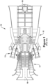
- Figures 1 through 3 illustrate an exemplary gas turbine in which embodiments of the present application may be used. It will be understood by those skilled in the art that the present invention is not limited to this type of usage. As stated, the present invention may be used in gas turbines, such as the engines used in power generation and airplanes, steam turbine engines, and other types of rotary engines. The examples provided are not meant to be limiting to the type of the turbine engine.
- Figure 1 is a schematic representation of a gas turbine 10. In general, gas turbines operate by extracting energy from a pressurized flow of hot gas produced by the combustion of a fuel in a stream of compressed air.
- gas turbine 10 may be configured with an axial compressor 11 that is mechanically coupled by a common shaft or rotor to a downstream turbine section or turbine 12, and a combustor 13 positioned between the compressor 11 and the turbine 12. As illustrated in Figure 1 , the gas turbine may be formed about a common central axis 19.
- Figure 2 illustrates a view of an exemplary multi-staged axial compressor 11 that may be used in the gas turbine of Figure 1 .
- the compressor 11 may have a plurality of stages, each of which include a row of compressor rotor blades 14 and a row of compressor stator blades 15.
- a first stage may include a row of compressor rotor blades 14, which rotate about a central shaft, followed by a row of compressor stator blades 15, which remain stationary during operation.
- Figure 3 illustrates a partial view of an exemplary turbine section or turbine 12 that may be used in the gas turbine of Figure 1 .
- the turbine 12 also may include a plurality of stages. Three exemplary stages are illustrated, but more or less may be present.
- Each stage may include a plurality of turbine nozzles or stator blades 17, which remain stationary during operation, followed by a plurality of turbine buckets or rotor blades 16, which rotate about the shaft during operation.
- the turbine stator blades 17 generally are circumferentially spaced one from the other and fixed about the axis of rotation to an outer casing.
- the turbine rotor blades 16 may be mounted on a turbine wheel or rotor disc (not shown) for rotation about the shaft (not shown). It will be appreciated that the turbine stator blades 17 and turbine rotor blades 16 lie in the hot gas path or working fluid flowpath through the turbine 12. The direction of flow of the combustion gases or working fluid within the working fluid flowpath is indicated by the arrow.
- the rotation of compressor rotor blades 14 within the axial compressor 11 may compress a flow of air.
- energy may be released when the compressed air is mixed with a fuel and ignited.
- the resulting flow of hot gases or working fluid from the combustor 13 is then directed over the turbine rotor blades 16, which induces the rotation of the turbine rotor blades 16 about the shaft.
- the energy of the flow of working fluid is transformed into the mechanical energy of the rotating blades and, given the connection between the rotor blades and the shaft, the rotating shaft.
- the mechanical energy of the may then be used to drive the rotation of the compressor rotor blades 14, such that the necessary supply of compressed air is produced, and also, for example, a generator to produce electricity.
- Figure 4 provides views of an exemplary compressor rotor blade 14 on which aspects of the present invention may be practiced. It will be appreciated that the present invention may be used on other types of blades, within both the turbine and the compressor, and that the exemplary blade of Figure 4 is provided primarily to illustrate and describe basic blade structure and related subcomponents.
- the rotor blade 14 may include a root 21 by which it attaches to a rotor disc.
- the root 21 may include a dovetail 22 configured for mounting in a corresponding dovetail slot in the perimeter of a rotor disc.
- the root 21 may further include a shank 23 that extends between the dovetail 22 and a platform 24.
- the platform 24, as shown, is disposed at the junction of the root 21 and an airfoil 25 that extends from it.
- the airfoil 25 may be configured to define a portion of the inboard boundary of the flowpath through the compressor 11. It will be appreciated that the airfoil 25 is the active component of the rotor blade 14 that interacts with the flow of working fluid through the compressor 11.
- the blade of this example is a compressor rotor blade 14, it will be appreciated that, unless otherwise stated, the present invention also may be applied to other types of blades within the gas turbine 10, including turbine rotor blades 16.
- the airfoil 25 of the rotor blade 14 may include a concave pressure side face 26 and a circumferentially or laterally opposite convex suction side face 27 extending axially between opposite leading and trailing edges 28, 29 respectively.
- the side faces 26 and 27 also extend in the radial direction from the platform 24 to an outboard tip 31 of the airfoil 25.
- Figure 5 shows an illustration of an exemplary inspection system 39 for inspecting surfaces of blades used in gas turbine engines.
- the system 39 includes a row 45 of rotor blades, only three of which are included in the illustration.
- the row 45 will be discussed as being a row of compressor rotor blades 14, though turbine rotor blades 16 also may be positioned and scanned in the same manner.
- the row 45 of rotor blades 14 may be in a dissembled condition relative to the turbine engine as a whole, though, the rotor blades 14 within the row 45 remains in an assembled condition with respect to the rotor disc 40.
- the rotor blades 14 making up the row 45 remain attached to the rotor disc 40.
- the rotor disc 40 is engaging by a gear mechanism 47.
- the gear mechanism 47 per the provided arrow, may controllably rotate the row 45 about a central axis.
- the rotor disc 40 may be rotated in a predetermined manner so to desirably index the rotor blades 14 mounted thereon past the inspection system 39.
- the rotor disc 40 being rotated is removed or disengaged from the shaft of the gas turbine engine and mounted upon the gear mechanism 47.
- the rotor disc 40 remains mounted on the engine's shaft and is rotated while on the shaft.
- the shaft may be considered part of the gear mechanism 47.
- the gear mechanism 47 may operate by rotating the rotor disc 40 via rotating the shaft on which the rotor disc 40 is mounted.
- the row 45 includes a gap 46 formed between each pair of neighboring rotor blades 14.
- Each of these gaps 46 is circumferentially defined between the pressure side face 26 of one of the neighboring rotor blades 14 and the suction side face 27 of the other.
- Radially, the gap 46 is defined between by the abutting platforms 24 of the neighboring rotor blades 14 and a reference plane formed between the outboard tips 31 of the neighboring blades. As will be understood, this reference plane may be designated the outboard mouth 48 of the gap 46.
- the gap 46 is described as being defined between a reference plane connecting the leading edges 28 of the neighboring rotor blades 14 and an opposing reference plane connecting the trailing edges of the neighboring rotor blades 14.
- the system 39 includes a scanner 41 attached to a movable arm 42.
- the scanner 41 may be connected to an end of a movable arm or arm 42, as illustrated.
- the opposing end of the arm 42 may connect to a stationary or movable base 55.
- the moveable arm 42 is configured as a retracting arm.
- the system may further include a computer 50 that electronically communicates with the scanner 41 and controls the movement of the arm 42.
- the movable arm 42 is configured for controllably moving the scanner 41 between an indexing position and a scanning position.
- the indexing position is one that is outside of the gaps 46 formed between one of the neighboring pairs of the rotor blades 14, whereas the scanning position is a positon that is inside one of the gaps 46 formed between the neighboring pairs of rotor blades 14.
- the scanning position is intended for performing the scans, while the indexing position is for removing the scanner 41 and arm 42 assembly from the gaps 46 to so allow relative movement between the assembly and the row of rotor blades 14 without damaging the scanner 41.
- the scanner 41 may project light 43 onto a blade surface within the gap 46 and may detect the projection of the light 43 on the blade surface within the gap 46.
- the scanner 41 may be configured for scanning the blade surface for surface defects and other characteristics, such as blade surface tears, rips, holes, cracks, pits, creep, and deformities.
- the scanner 41 includes opposed or differently aimed scanners that are configured to scan two different blade surfaces simultaneously. That is to say, the scanner 41 is configured such that it simultaneously scans the pressure side 26 of one of the neighboring blades 14 and the suction side of the other of the neighboring blade 14 that form the gap 46.
- the scanner 41 may be rotatably mounted to the movable arm 42.
- the light 43 projected by the scanner 41 may be used to profile in detail the scanned surface of the rotor blade 14, which may be used to detection of any flaws or defects that have formed thereon.
- the light 43 of the scanner 41 may be a form of structured light that changes its shape from an original array of pixels to a distorted array of pixels upon being projected onto the blade surface.
- the light 43 projected by the scanner 41 may be laser light.
- the light 43 projected by the scanner 41 may be visible light.
- the scanner 41 may further include a proximity sensor to recognize the position of the scanner 41 with respect to one of the blade surfaces within the gap 46.
- the proximity sensor may aid in positioning the scanner 41 within the gap 46 for accurate surface scans therein.
- the proximity sensor may comprise any conventional proximity sensor that, for example, emits an electromagnetic field and detects changes to the field resulting from surrounding objects inside the electromagnetic field.
- the proximity sensor may use sensing circuitry to detect these changes in the emitted electromagnetic field and transmit them to other parts of the system 39.
- the proximity sensor may comprise one or a plurality of proximity sensors including infrared, eddy current, capacitive, photoelectric, or inductive proximity sensors.
- the arm 42 may be configured to provide a mechanism for facilitating changes in position of the scanner 41 and to stand as a connecting structure between the scanner 41 and the base 55.
- the scanner 41 may attach to the arm 42 at any position thereon.
- the arm 42 may retract and extend, telescopically or otherwise, to predetermined lengths that place the sensor 41 alternatively within the gap 46 and outside of it.
- the arm 42 may include a desired pitch or angle to allow proper capture of the many types of blade surface that may be scanned during the scanning process.
- the arm 42 may include one or a plurality of joints along its length for improved maneuverability and flexibility in positioning.
- the indexing of the row of the rotor blades 14 by the gear mechanism 47 may include an intermittent rotation in which rotating periods alternate with stationary periods.
- the movable arm 42 may be configured to operate relative to the timing of the intermittent rotation such that the scanner 41 maintains the indexing position during the rotating periods and maintains the scanning position during the stationary periods.
- the base 55 may be attached to the arm 42 containing the scanner 41 and may be connected to a computer 50 through a cable or other means such as would allow wireless connection.
- the base 55 may adjust its position or height to allow for the arm 42 to position the scanner 41 properly along the blade surface. According to certain preferred embodiments, the base 55 may also be able to rotate along different axes as desired.
- the computer 50 may be connected to the base 55 via a cable or other means such as would allow wireless connection, and the computer 50 may perform analysis of the input from the scanner 41 that was received from the blade surface. The computer 50 may then calculate the differences between the input from the scanner 41 and a predetermined ideal blade surface. The computer 50 may then compare the differences between the input from the scanner 42 and the predetermined blade surface profile using predetermined thresholds for the differences.
- the computer 50 may ultimately make determinations as to whether the blade surface requires repair, and may recommend which repairs may be needed.
- the computer 50 may connect to a monitor 52 via a cable and may display an image 53, such as a three-dimensional image, of the scanned blade surface.
- the computer 50 may mark on each image 53 the areas in need of repair and may generate a report based on predetermined parameters that may describe, for example but not limited to, predicted changes in efficiency, performance, or other selected metrics that may occur after pursuing the recommended repair regimen for the blade surface.
- the computer 50 may create an output file that may contain inspected images of the blade surface in need of repair. This process may be repeated for every blade surface on the turbine to capture every surface in need of repair into one master output file or in any number of output files.
- the row 45 of the rotor blades may remain stationary while the device comprises a movable base 55 to which one or a plurality of arms 42 are attached, wherein the base 55 rotates itself around the turbine and scans the surfaces of each blade with the arm 42 and scanner 41 assembly.
- the base 55 may have multiple arms 42 each with include the scanner 41 that perform the same functions to read a plurality of blade surfaces at a plurality of locations or within a plurality of gaps 46 along the row 45 of rotor blades 14.
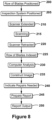
- Figure 8 is a flow diagram pursuant to an exemplary embodiment of a method for blade surface inspection in accordance with the present invention.
- the method in Figure 8 is presented in a specific order as an example only, and as such, the order of various parts of the method can be interchanged, omitted, and/or repeated without deviating from the invention.
- a row 45 of rotor blades 14 to be inspected may be engaged by the gear mechanism 47, which is configured to rotate the blades 14 at a predetermined rate about a central axis.
- the rotor disc 40 holding the rotor blades 14 may be engaged to the gear mechanism 47 and controllably rotated at predetermined timed increments.
- a device or inspection system 39 assembly may be desirably positioned near the row 45 of rotor blades 14.
- the inspection system 39 may include a base 55 and, extending from the base 55, an arm 42 and scanner 41 assembly. Further, the scanner 41 may be positioned at an indexing position, which is one outboard of the outboard mouth 48 of one of the gaps 46 that, as described, is formed between a neighboring pair of rotor blades 14.
- the arm 42 may be used to extend the scanner 41 to a scanning position, which is one in which the scanner 41 resides inside of the gap 46 formed between the neighboring rotor blades 14.
- the scanner 46 may move through the outboard mouth 48 of the gap 46, which, as stated, is formed as a reference plane connecting the outboard tips 31 of the airfoils 25 of the neighboring rotor blades 14.
- the scanner 41 may scan one or more blade surfaces on the neighboring rotor blades 14 for surface characteristics.
- the scanner 41 may be moved to a third position to scan other blade surfaces. Once the scanning is complete, at step 220, the scanner 41 may be retracted or be returned to the indexing position. Then, at a step 225, the row 45 of rotor blades 14 may be rotated or indexed such that, on complete, the scanner 41 will reside in the indexing position relative to a different one of the gaps 46 formed between the rotor blades 14.
- the method may be configured to accommodate the inspection system 39 having multiple arms 42 and scanners 41, as well as configurations in which the row 45 of rotor blades 14 remain stationary and the inspection system rotates about the row 45 of rotor blades 14.
- the computer 50 may analyze the input received from the scanner 41.
- the computer 30, for example, may calculate the differences between the input from the scanner, i.e., the scan results, and a predetermined ideal blade surface.
- the computer 50 may compare the differences between the input from the scanner and the predetermined ideal blade surface to predetermined thresholds.
- the computer 50 may construct and output a three-dimensional image 53 of the blade surface on a monitor 52 operably connected to the computer 50.
- the computer may indicate the areas of the blade surface that have been determined to require repair.
- the computer 50 may then create a report based on predetermined parameters that may describe, for example, predicted changes in efficiency, performance, or other metrics that may occur after pursuing the recommended repair of a blade surface.
- the computer 50 may output the report to an operator pursuant to conventional means.
Landscapes
- Engineering & Computer Science (AREA)
- General Engineering & Computer Science (AREA)
- Mechanical Engineering (AREA)
- General Physics & Mathematics (AREA)
- Chemical & Material Sciences (AREA)
- Physics & Mathematics (AREA)
- Analytical Chemistry (AREA)
- General Health & Medical Sciences (AREA)
- Immunology (AREA)
- Pathology (AREA)
- Biochemistry (AREA)
- Life Sciences & Earth Sciences (AREA)
- Health & Medical Sciences (AREA)
- Combustion & Propulsion (AREA)
- Structures Of Non-Positive Displacement Pumps (AREA)
- Turbine Rotor Nozzle Sealing (AREA)
- Investigating Materials By The Use Of Optical Means Adapted For Particular Applications (AREA)
Claims (11)
- Überprüfungssystem (39), umfassend:eine Anordnung, umfassend einen beweglichen Arm (42) und, auf dem beweglichen Arm (42) montiert, einen Scanner (41); undeine Reihe (45) von Rotorschaufeln (14, 16), die nahe der Anordnung für die Überprüfung positioniert sind, wobei die Reihe (45) mindestens eine Vielzahl der Rotorschaufeln (14, 16) einschließt, die um eine Mittelachse (19) in Umfangsrichtung beabstandet sind;wobei mindestens eine der Reihe (45) der Rotorschaufeln (14, 16) und der Anordnung relativ zueinander beweglich ist, um die Reihe (45) der Rotorschaufeln (14, 16) relativ zu der Anordnung zu indexieren,das System ferner umfassend eine Rotorscheibe (40), die einen Außenumfang aufweist, an dem die Rotorschaufeln (14, 16) der Reihe (45) der Rotorschaufeln (14, 16) montiert sind;wobei jede der Rotorschaufeln (14, 16) ein Schaufelblatt (25) einschließt, das zwischen einer konkaven Druckseitenfläche (26) und einer lateral gegenüberliegenden konvexen Saugseitenfläche (27) definiert ist, wobei sich die Druckseitenfläche (26) und die Saugseitenfläche (27) axial zwischen gegenüberliegenden Vorder- (28) und Hinterkanten (29) und radial zwischen einer Außenbordspitze (31) und einer Plattform (24) eines Fußes (21), der zum Montieren der Rotorschaufel (14, 16) auf die Rotorscheibe (40) konfiguriert ist, erstrecken; undwobei die Oberflächen für die Überprüfung mindestens eines umfassen von: der Druckseitenfläche (26) des Schaufelblatts (25), der Saugseitenfläche (27) des Schaufelblatts (25), der Außenbordspitze (31) des Schaufelblatts (25) und der Plattform (24);wobei die Reihe (45) der Rotorschaufeln (14, 16) vielfache benachbarte Paare der Rotorschaufeln (14, 16) einschließt; undwobei ein Spalt (46) zwischen den Schaufelblättern (25) jedes der benachbarten Paare der Rotorschaufeln (14, 16) ausgebildet ist, wobei der Spalt (46) definiert ist:in Umfangsrichtung zwischen der Druckseitenfläche (26) und der Saugseitenfläche (27) benachbarter Paare von Rotorschaufeln (14, 16);radial zwischen den Plattformen (24) der benachbarten Paare der Rotorschaufeln (14, 16) und einer Referenzebene, die Außenbordspitzen (31) der benachbarten Paare der Rotorschaufeln (14, 16) verbindet; undaxial zwischen einer Referenzebene, die die Vorderkanten (28) der benachbarten Paare der Rotorschaufeln (14, 16) verbindet, und einer Referenzebene, die die Hinterkanten (29) der benachbarten Paare der Rotorschaufeln (14, 16) verbindet; undwobei der bewegliche Arm (42) konfiguriert ist, um den Scanner (41) zwischen einer Indexierungsposition und einer Abtastposition steuerbar zu bewegen;wobei die Indexierungsposition eine Position außerhalb einem beliebigen der Spalte (46) umfasst, die zwischen den benachbarten Paaren der Rotorschaufeln (14, 16) ausgebildet sind;wobei die Abtastposition eine Position innerhalb einem der Spalte (46) umfasst, die zwischen den benachbarten Paaren der Rotorschaufeln (14, 16) ausgebildet sind;wobei der Scanner (41) an dem beweglichen Arm (42) angebracht ist;wobei der Scanner (41) eine Vielzahl von Abtastern umfasst, die in eine Vielzahl von Richtungen zum gleichzeitigen Abtasten einer Vielzahl der Oberflächen der Rotorschaufeln (14, 16) mit einem der Spalte (46) gerichtet sind, während der Scanner (41) in der Abtastposition ist; undwobei die vielfachen der Oberflächen, die gleichzeitig abgetastet werden, während der Scanner (41) in der Abtastposition ist, die Druckseite (26) einer ersten Rotorschaufel (14, 16) eines der benachbarten Paare von Rotorschaufeln (14, 16) und eine Saugseite (27) einer zweiten Rotorschaufel (14, 16) des einen der benachbarten Paare von Rotorschaufeln (14, 16) einschließen.
- System (39) nach Anspruch 1, ferner umfassend einen Getriebemechanismus (47), der mit der Rotorscheibe (40) verbunden ist, um die Reihe (45) der Rotorschaufeln (14, 16) um die Mittelachse herum zu drehen;
wobei die Anordnung eine stationäre Basis (55) umfasst, an der der bewegliche Arm (42) angebracht ist und wobei das Indexieren der Reihe (45) der Rotorschaufeln (14, 16) relativ zu der Anordnung das Drehen der Rotorscheibe (40) über den Getriebemechanismus (47) umfasst. - System (39) nach Anspruch 2, wobei die Außenbordspitzen (31) der Schaufelblätter (25) von jedem der benachbarten Paare der Rotorschaufeln (14, 16) eine Außenbordmündung (48) des Spalts (46) definieren;wobei beim Bewegen des Scanners (41) zwischen der Indexierungsposition in die Abtastposition, der bewegliche Arm (42) den Scanner (41) durch die Außenbordmündung (48) des Spalts (46) durchläuft; undwobei der Getriebemechanismus (47) eine Welle umfasst, auf der die Rotorscheibe (40) montiert ist, die Welle umfassend eine Mittelwelle eines Gasturbinentriebwerks (10), auf der die Rotorscheibe (40) während des Betriebs montiert ist.
- System (39) nach Anspruch 2, wobei die Oberflächeneigenschaften mindestens eines von einem Riss, einem Schlitz, einem Loch, einem Sprung, einer Vertiefung, einer Kriechdehnung und einer Verformung einschließen; undder bewegliche arm (42) einen einziehbaren Arm (42) umfasst,wobei der Getriebemechanismus (47) eine Welle umfasst, auf der die Rotorscheibe (40) montiert ist, die Welle umfassend eine separate Welle als eine Mittelwelle eines Gasturbinentriebwerks (10), auf der die Rotorscheibe (40) während des Betriebs montiert ist.
- System (39) nach Anspruch 2, wobei der Scanner (41) eine Lichtquelle umfasst, die Lichtquelle umfassend mindestens eines von: einer strukturierten Lichtquelle, einer Laserlichtquelle und einer sichtbaren Lichtquelle.
- System (39) nach Anspruch 5, wobei der Scanner (41) ferner einen Näherungssensor umfasst, der mindestens eines von einem Infrarot-Näherungssensor, einem Wirbelstrom-Näherungssensor, einem kapazitiven Näherungssensor, einem photoelektrischen Näherungssensor und einem induktiven Näherungssensor einschließt; und
wobei der Näherungssensor konfiguriert ist, um beim Positionieren des Scanners (41) zu unterstützen, durch Bewegen zwischen der Indexierungsposition und der Abtastposition. - System (39) nach Anspruch 2, wobei das Indexieren der Reihe (45) der Rotorschaufeln (14, 16) durch den Getriebemechanismus (47) eine intermittierende Drehung umfasst, in der sich Drehperioden mit stationären Perioden abwechseln; und
wobei der bewegliche Arm (42) konfiguriert ist, um relativ zu der intermittierenden 5 Drehung zu arbeiten, derart, dass der Scanner (41) in der Indexierungsposition während der Drehperioden und an der Abtastposition während der stationären Perioden positioniert ist. - System (39) nach einem der vorstehenden Ansprüche, ferner umfassend einen Computer (50), der mit der Anordnung wirkverbunden ist, wobei der Computer konfiguriert ist zum:Analysieren von Eingabe bezüglich der Oberflächeneigenschaften der Oberflächen, wie durch den Scanner (41) gescannt;Berechnen von Unterschieden zwischen der Eingabe von dem Scanner (41) und einer Referenzschaufeloberfläche; undVergleichen der Unterschiede zwischen der Eingabe von dem Scanner (41) und der Referenz 15-Schaufeloberfläche mit vorbestimmten Schwellenwerten.
- Verfahren zum Prüfen von Oberflächen von Rotorschaufeln (14, 16), die auf einer Rotorscheibe (40) für eine Oberflächeneigenschaft montiert sind, das Verfahren umfassend die Schritte:Positionieren einer Anordnung, die einen Scanner (41) einschließt, der auf einem beweglichen Arm (42) nahe der Rotorschaufeln (14, 16) montiert ist;Drehen der Rotorscheibe (40), um die Rotorschaufeln (14, 16) relativ zu der Anordnung zu indexieren;steuerbares Bewegen des Scanners (41) über den beweglichen Arm (42) zwischen einer Indexierungsposition und einer Abtastposition, wobei:die Indexierungsposition eine Position außerhalb von Spalten (46) umfasst, die zwischen den benachbarten Paaren der Rotorschaufeln (14, 16) ausgebildet sind;wobei die Abtastposition eine Position innerhalb einem der Spalte (46) umfasst, die zwischen benachbarten Paaren von Rotorschaufeln (14, 16) ausgebildet sind; das Verfahren ferner umfassend:Abtasten der Oberflächen der Rotorschaufeln (14, 16), wenn der Scanner (41) die Abtastposition beibehält;wobei jede der Rotorschaufeln (14, 16) ein Schaufelblatt (25) einschließt, das zwischen einer konkaven Druckseitenfläche (26) und einer lateral gegenüberliegenden konvexen Saugseitenfläche (27) definiert ist, wobei sich die Druckseitenfläche (26) und die Saugseitenfläche (27) axial zwischen gegenüberliegenden Vorder- (28) und Hinterkanten (29) und radial zwischen einer Außenbordspitze (31) und einer Plattform (24) eines Fußes (21), der zum Montieren der Rotorschaufel (14, 16) auf die Rotorscheibe (40) konfiguriert ist, erstrecken;wobei die Oberflächen für die Überprüfung mindestens eines umfassen von: der Druckseitenfläche (26) des Schaufelblatts (25); der Saugseitenfläche (27) des Schaufelblatts (25); der Außenbordspitze (31) des Schaufelblatts (25); und der Plattform (24); undwobei das Abtasten der Oberflächen der Rotorschaufeln (14, 16) ein gleichzeitiges Abtasten einer Vielzahl der Oberflächen der Rotorschaufeln (14, 16) mit einem der Spalte (46) gerichtet sind, während der Scanner (41) in der Abtastposition ist, wobei die vielfachen der Oberflächen, die gleichzeitig abgetastet werden, während der Scanner (41) in der Abtastposition ist, die Druckseite (26) einer ersten Rotorschaufel (14, 16) eines der benachbarten Paare von Rotorschaufeln (14, 16) und eine Saugseite (27) einer zweiten Rotorschaufel (14, 16) des einen der benachbarten Paare von Rotorschaufeln (14, 16) einschließen.
- Verfahren nach Anspruch 9, wobei die Rotorschaufeln (14, 16) vielfache benachbarte Paare der Rotorschaufeln (14, 16) einschließen; und
wobei der Spalt (46) zwischen den Schaufelblättern (25) jedes der benachbarten Paare der Rotorschaufeln (14, 16) ausgebildet ist, wobei der Spalt (46) definiert ist:in Umfangsrichtung zwischen der Druckseitenfläche (26) und der Saugseitenfläche (27) der benachbarten Paare der Rotorschaufeln (14, 16);radial zwischen den Plattformen (24) der benachbarten Paare der Rotorschaufeln (14, 16) und einer Referenzebene, die Außenbordspitzen (31) der benachbarten Paare der Rotorschaufeln (14, 16) verbindet; und axial zwischen einer Referenzebene, die die Vorderkanten (28) der benachbarten Paare der Rotorschaufeln (14, 16) verbindet, und einer Referenzebene, die die Hinterkanten (29) benachbarter Paare von Rotorschaufeln (14, 16) verbindet; undwobei beim steuerbaren Bewegen des Scanners (41) zwischen der Indexierungsposition und der Abtastposition der bewegliche Arm (42) den Scanner (41) durch die Referenzebene durchläuft, die die Außenbordspitzen (31) der benachbarten Paare der Rotorschaufeln (14, 16) verbindet. - Verfahren nach dem vorstehenden Anspruch, wobei der Scanner (41) ferner eine strukturierte Lichtquelle umfasst;wobei das Drehen der Rotorscheibe (40) eine intermittierende Drehung umfasst, in der sich Drehperioden mit stationären Perioden abwechseln; undwobei das steuerbare Bewegen des Scanners (41) über den beweglichen Arm (42) zwischen der Indexierungsposition und der Abtastposition einschließt: Zeittaktung der Bewegung gemäß der intermittierenden Drehung, derart, dass der Scanner (41) die Indexierungsposition während der Drehperioden und die Abtastposition während der stationären Perioden umfasst.
Applications Claiming Priority (1)
| Application Number | Priority Date | Filing Date | Title |
|---|---|---|---|
| US14/974,210 US9733195B2 (en) | 2015-12-18 | 2015-12-18 | System and method for inspecting turbine blades |
Publications (2)
| Publication Number | Publication Date |
|---|---|
| EP3182102A1 EP3182102A1 (de) | 2017-06-21 |
| EP3182102B1 true EP3182102B1 (de) | 2024-01-24 |
Family
ID=57539142
Family Applications (1)
| Application Number | Title | Priority Date | Filing Date |
|---|---|---|---|
| EP16203161.1A Active EP3182102B1 (de) | 2015-12-18 | 2016-12-09 | System und verfahren zum prüfen von turbinenschaufeln |
Country Status (4)
| Country | Link |
|---|---|
| US (1) | US9733195B2 (de) |
| EP (1) | EP3182102B1 (de) |
| JP (1) | JP6812225B2 (de) |
| CN (1) | CN107035432A (de) |
Families Citing this family (39)
| Publication number | Priority date | Publication date | Assignee | Title |
|---|---|---|---|---|
| US10730185B2 (en) | 2018-04-10 | 2020-08-04 | General Electric Company | Systems and methods for inspecting, cleaning, and/or repairing one or more blades attached to a rotor of a gas turbine engine using a robotic system |
| US12194620B2 (en) | 2018-10-15 | 2025-01-14 | Oliver Crisipin Robotics Limited | Selectively flexible extension tool |
| US11707819B2 (en) | 2018-10-15 | 2023-07-25 | General Electric Company | Selectively flexible extension tool |
| CN109209988B (zh) * | 2018-11-22 | 2024-04-12 | 无锡市海星船舶动力有限公司 | 具有叶片均匀分布检测功能的压缩机叶轮 |
| US11103964B2 (en) * | 2018-12-06 | 2021-08-31 | General Electric Company | Service apparatus for use with rotary machines |
| US11702955B2 (en) | 2019-01-14 | 2023-07-18 | General Electric Company | Component repair system and method |
| US12405187B2 (en) | 2019-10-04 | 2025-09-02 | General Electric Company | Insertion apparatus for use with rotary machines |
| US11170495B2 (en) * | 2019-10-21 | 2021-11-09 | The Boeing Company | Scanning apparatus and method of scanning |
| US11752622B2 (en) | 2020-01-23 | 2023-09-12 | General Electric Company | Extension tool having a plurality of links |
| US11692650B2 (en) | 2020-01-23 | 2023-07-04 | General Electric Company | Selectively flexible extension tool |
| US11613003B2 (en) | 2020-01-24 | 2023-03-28 | General Electric Company | Line assembly for an extension tool having a plurality of links |
| US10866196B1 (en) * | 2020-02-17 | 2020-12-15 | General Electric Company | Systems and methods for use in performing maintenance on a turbine rotor |
| US11371437B2 (en) | 2020-03-10 | 2022-06-28 | Oliver Crispin Robotics Limited | Insertion tool |
| US12091981B2 (en) * | 2020-06-11 | 2024-09-17 | General Electric Company | Insertion tool and method |
| CN112858327A (zh) * | 2020-12-31 | 2021-05-28 | 常州市智鸿机械有限公司 | 一种自动汽轮机叶片检测装置 |
| US12416800B2 (en) | 2021-01-08 | 2025-09-16 | General Electric Company | Insertion tool |
| US12504616B2 (en) | 2021-01-08 | 2025-12-23 | General Electric Company | Insertion tool |
| US11654547B2 (en) | 2021-03-31 | 2023-05-23 | General Electric Company | Extension tool |
| JP7499211B2 (ja) * | 2021-04-30 | 2024-06-13 | 三菱電機プラントエンジニアリング株式会社 | 発電機点検装置、発電機点検方法、および発電機点検プログラム |
| IT202100012590A1 (it) | 2021-05-17 | 2022-11-17 | Nuovo Pignone Tecnologie Srl | Apparato e metodo per ispezionare automaticamente componenti di macchina |
| CN113418709B (zh) * | 2021-08-24 | 2022-01-25 | 中国航发上海商用航空发动机制造有限责任公司 | 一种机匣包容试验装置及其设计方法 |
| US20230305156A1 (en) * | 2022-03-23 | 2023-09-28 | Raytheon Technologies Corporation | Dual scanner inspection systems and methods |
| US20230304476A1 (en) * | 2022-03-23 | 2023-09-28 | Raytheon Technologies Corporation | Feedback inspection systems and methods |
| US12468869B2 (en) | 2022-03-23 | 2025-11-11 | Rtx Corporation | Inspection systems and methods with airfoil sheaths |
| US12163897B2 (en) * | 2022-03-23 | 2024-12-10 | Rtx Corporation | Multi-stage inspection systems and methods |
| US11860060B2 (en) | 2022-04-05 | 2024-01-02 | Rtx Corporation | Integrally bladed rotor analysis and repair systems and methods |
| US20230315069A1 (en) * | 2022-04-05 | 2023-10-05 | Raytheon Technologies Corporation | Inspection data management systems and methods |
| US12318877B2 (en) * | 2022-04-05 | 2025-06-03 | Rtx Corporation | Blend approach based inspection and analysis systems and methods |
| US12523979B2 (en) | 2022-04-05 | 2026-01-13 | Rtx Corporation | Method of repairing a stack of integrally bladed rotors |
| US20230315937A1 (en) * | 2022-04-05 | 2023-10-05 | Raytheon Technologies Corporation | Partial repair systems and methods for integrally bladed rotors |
| US12037918B2 (en) * | 2022-04-05 | 2024-07-16 | Rtx Corporation | Systems and methods for parameterization of inspected bladed rotor analysis |
| US12410711B2 (en) | 2022-04-05 | 2025-09-09 | Rtx Corporation | Bladed rotor inspection, analysis and repair systems and methods |
| US12044632B2 (en) | 2022-05-13 | 2024-07-23 | Rtx Corporation | Airfoil tip cleaning and assessment systems and methods |
| US12442634B2 (en) * | 2022-05-13 | 2025-10-14 | Rtx Corporation | Visual and/or dimensional tip inspection systems and methods |
| US11725517B1 (en) | 2022-05-13 | 2023-08-15 | Raytheon Technologies Corporation | Airfoil tip cleaning and assessment systems and methods |
| US12394179B2 (en) | 2022-07-29 | 2025-08-19 | Rtx Corporation | Performing vane classification for turbine engines using structured light three-dimensional (3D) scans |
| US12163438B2 (en) | 2022-08-11 | 2024-12-10 | Rtx Corporation | Detection of gas turbine engine blade abnormalities based on light reflections |
| CN120020516B (zh) * | 2023-11-17 | 2025-11-25 | 中国航发商用航空发动机有限责任公司 | 磁控变桨距联调装置、开式转子发动机和涡轮螺旋桨发动机试验件 |
| CN117538260A (zh) * | 2023-12-12 | 2024-02-09 | 广东省科学院佛山产业技术研究院有限公司 | 一种用于高速风机的外形检测装置 |
Citations (1)
| Publication number | Priority date | Publication date | Assignee | Title |
|---|---|---|---|---|
| EP2363575A2 (de) * | 2010-02-26 | 2011-09-07 | General Electric Company | System und Verfahren zur Überprüfung von Leitschaufeln |
Family Cites Families (18)
| Publication number | Priority date | Publication date | Assignee | Title |
|---|---|---|---|---|
| US4501095A (en) * | 1983-06-07 | 1985-02-26 | United Technologies Corporation | Method and apparatus for grinding turbine engine rotor assemblies using dynamic optical measurement system |
| JPH11214484A (ja) * | 1998-01-27 | 1999-08-06 | Nikon Corp | 基板検出装置 |
| US6341936B1 (en) | 2000-04-21 | 2002-01-29 | General Electric Company | FOD inspection of laser shock peened gas turbine engine airfoils |
| US7152832B2 (en) * | 2001-04-23 | 2006-12-26 | Wochnick Patrick A | Pipe support apparatus |
| GB0210990D0 (en) | 2002-05-14 | 2002-06-19 | Rolls Royce Plc | Method of generating an inspection program and method of generating a visual display |
| US6932570B2 (en) * | 2002-05-23 | 2005-08-23 | General Electric Company | Methods and apparatus for extending gas turbine engine airfoils useful life |
| US6912446B2 (en) | 2002-10-23 | 2005-06-28 | General Electric Company | Systems and methods for automated sensing and machining for repairing airfoils of blades |
| US7365862B2 (en) | 2005-10-24 | 2008-04-29 | General Electric Company | Methods and apparatus for inspecting an object |
| JP4869699B2 (ja) * | 2005-12-13 | 2012-02-08 | オリンパス株式会社 | 内視鏡装置 |
| DE102008005554A1 (de) | 2008-01-22 | 2009-07-23 | Rolls-Royce Deutschland Ltd & Co Kg | Vorrichtung und Verfahren zur Untersuchung der Oberfläche eines Bauteils |
| US8791998B2 (en) * | 2009-07-31 | 2014-07-29 | Olympus Corporation | Image processing apparatus and method for displaying images |
| US7966856B1 (en) * | 2009-12-15 | 2011-06-28 | General Electric Company | Robotic peening apparatus |
| US8899115B2 (en) * | 2011-04-20 | 2014-12-02 | United Technologies Corporation | Method and system for locating a laser vibrometer during non-contact scanning |
| US9154743B2 (en) * | 2012-01-31 | 2015-10-06 | Siemens Energy, Inc. | System and method for optical inspection of off-line industrial gas turbines and other power generation machinery while in turning gear mode |
| EP2662535A1 (de) * | 2012-05-07 | 2013-11-13 | Siemens Aktiengesellschaft | Rotor für eine Dampfturbine und zugehörige Dampfturbine |
| EP2888577B1 (de) * | 2012-08-23 | 2017-05-31 | Siemens Energy, Inc. | System und verfahren zur visuellen inspektion und 3d-weisslichtabtastung von industriellen offline -gasturbinen und anderen stromerzeugungsmaschinen |
| JP6180221B2 (ja) * | 2013-08-01 | 2017-08-16 | オリンパス株式会社 | ブレード検査装置 |
| US20150176413A1 (en) * | 2013-12-20 | 2015-06-25 | General Electric Company | Snubber configurations for turbine rotor blades |
-
2015
- 2015-12-18 US US14/974,210 patent/US9733195B2/en active Active
-
2016
- 2016-12-09 EP EP16203161.1A patent/EP3182102B1/de active Active
- 2016-12-09 JP JP2016238974A patent/JP6812225B2/ja active Active
- 2016-12-16 CN CN201611166428.9A patent/CN107035432A/zh active Pending
Patent Citations (1)
| Publication number | Priority date | Publication date | Assignee | Title |
|---|---|---|---|---|
| EP2363575A2 (de) * | 2010-02-26 | 2011-09-07 | General Electric Company | System und Verfahren zur Überprüfung von Leitschaufeln |
Also Published As
| Publication number | Publication date |
|---|---|
| JP2017125843A (ja) | 2017-07-20 |
| US9733195B2 (en) | 2017-08-15 |
| EP3182102A1 (de) | 2017-06-21 |
| US20170176342A1 (en) | 2017-06-22 |
| CN107035432A (zh) | 2017-08-11 |
| JP6812225B2 (ja) | 2021-01-13 |
Similar Documents
| Publication | Publication Date | Title |
|---|---|---|
| EP3182102B1 (de) | System und verfahren zum prüfen von turbinenschaufeln | |
| EP2597273B1 (de) | Vorrichtung und Verfahren zur Inspektion einer Turbomaschine | |
| EP3623788B1 (de) | Automatisiertes notrangordnungssystem | |
| US6886422B2 (en) | Methods and apparatus for inspecting components | |
| EP3168591A1 (de) | Systeme und verfahren zur überwachung von komponenten | |
| US20250060206A1 (en) | Feedback inspection systems and methods | |
| EP4249731A1 (de) | Mehrstufige inspektionssysteme und -verfahren | |
| US20230314341A1 (en) | Data transfer systems and methods for analysis inputs | |
| EP4269753A1 (de) | Inspektionssysteme und -verfahren zur abdichtung von oberflächen | |
| US12410711B2 (en) | Bladed rotor inspection, analysis and repair systems and methods | |
| US20230315949A1 (en) | Systems and methods for structural analysis for inspected bladed rotors | |
| US20230315951A1 (en) | Systems and methods for inspected bladed rotor analysis | |
| EP4249900A1 (de) | Feedback-inspektionssysteme und -verfahren | |
| US20230315937A1 (en) | Partial repair systems and methods for integrally bladed rotors | |
| US12468869B2 (en) | Inspection systems and methods with airfoil sheaths | |
| US20230305156A1 (en) | Dual scanner inspection systems and methods | |
| EP4667923A1 (de) | Inspektionssystem zur erkennung von oberflächenrissen mittels wirbelstromthermografie | |
| US20230315069A1 (en) | Inspection data management systems and methods |
Legal Events
| Date | Code | Title | Description |
|---|---|---|---|
| PUAI | Public reference made under article 153(3) epc to a published international application that has entered the european phase |
Free format text: ORIGINAL CODE: 0009012 |
|
| STAA | Information on the status of an ep patent application or granted ep patent |
Free format text: STATUS: THE APPLICATION HAS BEEN PUBLISHED |
|
| AK | Designated contracting states |
Kind code of ref document: A1 Designated state(s): AL AT BE BG CH CY CZ DE DK EE ES FI FR GB GR HR HU IE IS IT LI LT LU LV MC MK MT NL NO PL PT RO RS SE SI SK SM TR |
|
| AX | Request for extension of the european patent |
Extension state: BA ME |
|
| STAA | Information on the status of an ep patent application or granted ep patent |
Free format text: STATUS: REQUEST FOR EXAMINATION WAS MADE |
|
| 17P | Request for examination filed |
Effective date: 20171221 |
|
| RBV | Designated contracting states (corrected) |
Designated state(s): AL AT BE BG CH CY CZ DE DK EE ES FI FR GB GR HR HU IE IS IT LI LT LU LV MC MK MT NL NO PL PT RO RS SE SI SK SM TR |
|
| STAA | Information on the status of an ep patent application or granted ep patent |
Free format text: STATUS: EXAMINATION IS IN PROGRESS |
|
| 17Q | First examination report despatched |
Effective date: 20200313 |
|
| GRAP | Despatch of communication of intention to grant a patent |
Free format text: ORIGINAL CODE: EPIDOSNIGR1 |
|
| STAA | Information on the status of an ep patent application or granted ep patent |
Free format text: STATUS: GRANT OF PATENT IS INTENDED |
|
| INTG | Intention to grant announced |
Effective date: 20230907 |
|
| GRAS | Grant fee paid |
Free format text: ORIGINAL CODE: EPIDOSNIGR3 |
|
| RAP1 | Party data changed (applicant data changed or rights of an application transferred) |
Owner name: GENERAL ELECTRIC TECHNOLOGY GMBH |
|
| GRAA | (expected) grant |
Free format text: ORIGINAL CODE: 0009210 |
|
| STAA | Information on the status of an ep patent application or granted ep patent |
Free format text: STATUS: THE PATENT HAS BEEN GRANTED |
|
| AK | Designated contracting states |
Kind code of ref document: B1 Designated state(s): AL AT BE BG CH CY CZ DE DK EE ES FI FR GB GR HR HU IE IS IT LI LT LU LV MC MK MT NL NO PL PT RO RS SE SI SK SM TR |
|
| REG | Reference to a national code |
Ref country code: GB Ref legal event code: FG4D |
|
| REG | Reference to a national code |
Ref country code: CH Ref legal event code: EP |
|
| REG | Reference to a national code |
Ref country code: IE Ref legal event code: FG4D |
|
| REG | Reference to a national code |
Ref country code: DE Ref legal event code: R096 Ref document number: 602016085455 Country of ref document: DE |
|
| REG | Reference to a national code |
Ref country code: LT Ref legal event code: MG9D |
|
| REG | Reference to a national code |
Ref country code: NL Ref legal event code: MP Effective date: 20240124 |
|
| PG25 | Lapsed in a contracting state [announced via postgrant information from national office to epo] |
Ref country code: NL Free format text: LAPSE BECAUSE OF FAILURE TO SUBMIT A TRANSLATION OF THE DESCRIPTION OR TO PAY THE FEE WITHIN THE PRESCRIBED TIME-LIMIT Effective date: 20240124 |
|
| PG25 | Lapsed in a contracting state [announced via postgrant information from national office to epo] |
Ref country code: NL Free format text: LAPSE BECAUSE OF FAILURE TO SUBMIT A TRANSLATION OF THE DESCRIPTION OR TO PAY THE FEE WITHIN THE PRESCRIBED TIME-LIMIT Effective date: 20240124 |
|
| PG25 | Lapsed in a contracting state [announced via postgrant information from national office to epo] |
Ref country code: IS Free format text: LAPSE BECAUSE OF FAILURE TO SUBMIT A TRANSLATION OF THE DESCRIPTION OR TO PAY THE FEE WITHIN THE PRESCRIBED TIME-LIMIT Effective date: 20240524 |
|
| PG25 | Lapsed in a contracting state [announced via postgrant information from national office to epo] |
Ref country code: LT Free format text: LAPSE BECAUSE OF FAILURE TO SUBMIT A TRANSLATION OF THE DESCRIPTION OR TO PAY THE FEE WITHIN THE PRESCRIBED TIME-LIMIT Effective date: 20240124 |
|
| PG25 | Lapsed in a contracting state [announced via postgrant information from national office to epo] |
Ref country code: GR Free format text: LAPSE BECAUSE OF FAILURE TO SUBMIT A TRANSLATION OF THE DESCRIPTION OR TO PAY THE FEE WITHIN THE PRESCRIBED TIME-LIMIT Effective date: 20240425 |
|
| REG | Reference to a national code |
Ref country code: AT Ref legal event code: MK05 Ref document number: 1652540 Country of ref document: AT Kind code of ref document: T Effective date: 20240124 |
|
| PG25 | Lapsed in a contracting state [announced via postgrant information from national office to epo] |
Ref country code: RS Free format text: LAPSE BECAUSE OF FAILURE TO SUBMIT A TRANSLATION OF THE DESCRIPTION OR TO PAY THE FEE WITHIN THE PRESCRIBED TIME-LIMIT Effective date: 20240424 Ref country code: HR Free format text: LAPSE BECAUSE OF FAILURE TO SUBMIT A TRANSLATION OF THE DESCRIPTION OR TO PAY THE FEE WITHIN THE PRESCRIBED TIME-LIMIT Effective date: 20240124 |
|
| PG25 | Lapsed in a contracting state [announced via postgrant information from national office to epo] |
Ref country code: ES Free format text: LAPSE BECAUSE OF FAILURE TO SUBMIT A TRANSLATION OF THE DESCRIPTION OR TO PAY THE FEE WITHIN THE PRESCRIBED TIME-LIMIT Effective date: 20240124 |
|
| PG25 | Lapsed in a contracting state [announced via postgrant information from national office to epo] |
Ref country code: AT Free format text: LAPSE BECAUSE OF FAILURE TO SUBMIT A TRANSLATION OF THE DESCRIPTION OR TO PAY THE FEE WITHIN THE PRESCRIBED TIME-LIMIT Effective date: 20240124 |
|
| PG25 | Lapsed in a contracting state [announced via postgrant information from national office to epo] |
Ref country code: RS Free format text: LAPSE BECAUSE OF FAILURE TO SUBMIT A TRANSLATION OF THE DESCRIPTION OR TO PAY THE FEE WITHIN THE PRESCRIBED TIME-LIMIT Effective date: 20240424 Ref country code: NO Free format text: LAPSE BECAUSE OF FAILURE TO SUBMIT A TRANSLATION OF THE DESCRIPTION OR TO PAY THE FEE WITHIN THE PRESCRIBED TIME-LIMIT Effective date: 20240424 Ref country code: LT Free format text: LAPSE BECAUSE OF FAILURE TO SUBMIT A TRANSLATION OF THE DESCRIPTION OR TO PAY THE FEE WITHIN THE PRESCRIBED TIME-LIMIT Effective date: 20240124 Ref country code: IS Free format text: LAPSE BECAUSE OF FAILURE TO SUBMIT A TRANSLATION OF THE DESCRIPTION OR TO PAY THE FEE WITHIN THE PRESCRIBED TIME-LIMIT Effective date: 20240524 Ref country code: HR Free format text: LAPSE BECAUSE OF FAILURE TO SUBMIT A TRANSLATION OF THE DESCRIPTION OR TO PAY THE FEE WITHIN THE PRESCRIBED TIME-LIMIT Effective date: 20240124 Ref country code: GR Free format text: LAPSE BECAUSE OF FAILURE TO SUBMIT A TRANSLATION OF THE DESCRIPTION OR TO PAY THE FEE WITHIN THE PRESCRIBED TIME-LIMIT Effective date: 20240425 Ref country code: FI Free format text: LAPSE BECAUSE OF FAILURE TO SUBMIT A TRANSLATION OF THE DESCRIPTION OR TO PAY THE FEE WITHIN THE PRESCRIBED TIME-LIMIT Effective date: 20240124 Ref country code: ES Free format text: LAPSE BECAUSE OF FAILURE TO SUBMIT A TRANSLATION OF THE DESCRIPTION OR TO PAY THE FEE WITHIN THE PRESCRIBED TIME-LIMIT Effective date: 20240124 Ref country code: BG Free format text: LAPSE BECAUSE OF FAILURE TO SUBMIT A TRANSLATION OF THE DESCRIPTION OR TO PAY THE FEE WITHIN THE PRESCRIBED TIME-LIMIT Effective date: 20240124 Ref country code: AT Free format text: LAPSE BECAUSE OF FAILURE TO SUBMIT A TRANSLATION OF THE DESCRIPTION OR TO PAY THE FEE WITHIN THE PRESCRIBED TIME-LIMIT Effective date: 20240124 |
|
| PG25 | Lapsed in a contracting state [announced via postgrant information from national office to epo] |
Ref country code: PT Free format text: LAPSE BECAUSE OF FAILURE TO SUBMIT A TRANSLATION OF THE DESCRIPTION OR TO PAY THE FEE WITHIN THE PRESCRIBED TIME-LIMIT Effective date: 20240524 Ref country code: PL Free format text: LAPSE BECAUSE OF FAILURE TO SUBMIT A TRANSLATION OF THE DESCRIPTION OR TO PAY THE FEE WITHIN THE PRESCRIBED TIME-LIMIT Effective date: 20240124 |
|
| PG25 | Lapsed in a contracting state [announced via postgrant information from national office to epo] |
Ref country code: SE Free format text: LAPSE BECAUSE OF FAILURE TO SUBMIT A TRANSLATION OF THE DESCRIPTION OR TO PAY THE FEE WITHIN THE PRESCRIBED TIME-LIMIT Effective date: 20240124 Ref country code: PT Free format text: LAPSE BECAUSE OF FAILURE TO SUBMIT A TRANSLATION OF THE DESCRIPTION OR TO PAY THE FEE WITHIN THE PRESCRIBED TIME-LIMIT Effective date: 20240524 Ref country code: PL Free format text: LAPSE BECAUSE OF FAILURE TO SUBMIT A TRANSLATION OF THE DESCRIPTION OR TO PAY THE FEE WITHIN THE PRESCRIBED TIME-LIMIT Effective date: 20240124 Ref country code: LV Free format text: LAPSE BECAUSE OF FAILURE TO SUBMIT A TRANSLATION OF THE DESCRIPTION OR TO PAY THE FEE WITHIN THE PRESCRIBED TIME-LIMIT Effective date: 20240124 |
|
| PG25 | Lapsed in a contracting state [announced via postgrant information from national office to epo] |
Ref country code: DK Free format text: LAPSE BECAUSE OF FAILURE TO SUBMIT A TRANSLATION OF THE DESCRIPTION OR TO PAY THE FEE WITHIN THE PRESCRIBED TIME-LIMIT Effective date: 20240124 |
|
| PG25 | Lapsed in a contracting state [announced via postgrant information from national office to epo] |
Ref country code: SM Free format text: LAPSE BECAUSE OF FAILURE TO SUBMIT A TRANSLATION OF THE DESCRIPTION OR TO PAY THE FEE WITHIN THE PRESCRIBED TIME-LIMIT Effective date: 20240124 |
|
| PG25 | Lapsed in a contracting state [announced via postgrant information from national office to epo] |
Ref country code: EE Free format text: LAPSE BECAUSE OF FAILURE TO SUBMIT A TRANSLATION OF THE DESCRIPTION OR TO PAY THE FEE WITHIN THE PRESCRIBED TIME-LIMIT Effective date: 20240124 Ref country code: CZ Free format text: LAPSE BECAUSE OF FAILURE TO SUBMIT A TRANSLATION OF THE DESCRIPTION OR TO PAY THE FEE WITHIN THE PRESCRIBED TIME-LIMIT Effective date: 20240124 |
|
| REG | Reference to a national code |
Ref country code: DE Ref legal event code: R097 Ref document number: 602016085455 Country of ref document: DE |
|
| PG25 | Lapsed in a contracting state [announced via postgrant information from national office to epo] |
Ref country code: SK Free format text: LAPSE BECAUSE OF FAILURE TO SUBMIT A TRANSLATION OF THE DESCRIPTION OR TO PAY THE FEE WITHIN THE PRESCRIBED TIME-LIMIT Effective date: 20240124 |
|
| PG25 | Lapsed in a contracting state [announced via postgrant information from national office to epo] |
Ref country code: SM Free format text: LAPSE BECAUSE OF FAILURE TO SUBMIT A TRANSLATION OF THE DESCRIPTION OR TO PAY THE FEE WITHIN THE PRESCRIBED TIME-LIMIT Effective date: 20240124 Ref country code: SK Free format text: LAPSE BECAUSE OF FAILURE TO SUBMIT A TRANSLATION OF THE DESCRIPTION OR TO PAY THE FEE WITHIN THE PRESCRIBED TIME-LIMIT Effective date: 20240124 Ref country code: RO Free format text: LAPSE BECAUSE OF FAILURE TO SUBMIT A TRANSLATION OF THE DESCRIPTION OR TO PAY THE FEE WITHIN THE PRESCRIBED TIME-LIMIT Effective date: 20240124 Ref country code: EE Free format text: LAPSE BECAUSE OF FAILURE TO SUBMIT A TRANSLATION OF THE DESCRIPTION OR TO PAY THE FEE WITHIN THE PRESCRIBED TIME-LIMIT Effective date: 20240124 Ref country code: DK Free format text: LAPSE BECAUSE OF FAILURE TO SUBMIT A TRANSLATION OF THE DESCRIPTION OR TO PAY THE FEE WITHIN THE PRESCRIBED TIME-LIMIT Effective date: 20240124 Ref country code: CZ Free format text: LAPSE BECAUSE OF FAILURE TO SUBMIT A TRANSLATION OF THE DESCRIPTION OR TO PAY THE FEE WITHIN THE PRESCRIBED TIME-LIMIT Effective date: 20240124 |
|
| PLBE | No opposition filed within time limit |
Free format text: ORIGINAL CODE: 0009261 |
|
| STAA | Information on the status of an ep patent application or granted ep patent |
Free format text: STATUS: NO OPPOSITION FILED WITHIN TIME LIMIT |
|
| PG25 | Lapsed in a contracting state [announced via postgrant information from national office to epo] |
Ref country code: IT Free format text: LAPSE BECAUSE OF FAILURE TO SUBMIT A TRANSLATION OF THE DESCRIPTION OR TO PAY THE FEE WITHIN THE PRESCRIBED TIME-LIMIT Effective date: 20240124 |
|
| PG25 | Lapsed in a contracting state [announced via postgrant information from national office to epo] |
Ref country code: IT Free format text: LAPSE BECAUSE OF FAILURE TO SUBMIT A TRANSLATION OF THE DESCRIPTION OR TO PAY THE FEE WITHIN THE PRESCRIBED TIME-LIMIT Effective date: 20240124 |
|
| 26N | No opposition filed |
Effective date: 20241025 |
|
| PG25 | Lapsed in a contracting state [announced via postgrant information from national office to epo] |
Ref country code: SI Free format text: LAPSE BECAUSE OF FAILURE TO SUBMIT A TRANSLATION OF THE DESCRIPTION OR TO PAY THE FEE WITHIN THE PRESCRIBED TIME-LIMIT Effective date: 20240124 |
|
| PG25 | Lapsed in a contracting state [announced via postgrant information from national office to epo] |
Ref country code: MC Free format text: LAPSE BECAUSE OF FAILURE TO SUBMIT A TRANSLATION OF THE DESCRIPTION OR TO PAY THE FEE WITHIN THE PRESCRIBED TIME-LIMIT Effective date: 20240124 |
|
| REG | Reference to a national code |
Ref country code: CH Ref legal event code: PL |
|
| PG25 | Lapsed in a contracting state [announced via postgrant information from national office to epo] |
Ref country code: LU Free format text: LAPSE BECAUSE OF NON-PAYMENT OF DUE FEES Effective date: 20241209 |
|
| REG | Reference to a national code |
Ref country code: BE Ref legal event code: MM Effective date: 20241231 |
|
| PG25 | Lapsed in a contracting state [announced via postgrant information from national office to epo] |
Ref country code: BE Free format text: LAPSE BECAUSE OF NON-PAYMENT OF DUE FEES Effective date: 20241231 |
|
| PG25 | Lapsed in a contracting state [announced via postgrant information from national office to epo] |
Ref country code: CH Free format text: LAPSE BECAUSE OF NON-PAYMENT OF DUE FEES Effective date: 20241231 |
|
| PG25 | Lapsed in a contracting state [announced via postgrant information from national office to epo] |
Ref country code: IE Free format text: LAPSE BECAUSE OF NON-PAYMENT OF DUE FEES Effective date: 20241209 |
|
| PGFP | Annual fee paid to national office [announced via postgrant information from national office to epo] |
Ref country code: DE Payment date: 20251126 Year of fee payment: 10 |
|
| PGFP | Annual fee paid to national office [announced via postgrant information from national office to epo] |
Ref country code: GB Payment date: 20251119 Year of fee payment: 10 |
|
| PGFP | Annual fee paid to national office [announced via postgrant information from national office to epo] |
Ref country code: FR Payment date: 20251119 Year of fee payment: 10 |