EP3182143A1 - Rogowski-stromsensor, schutz- und messvorrichtung, und elektrischer schutzschalter mit solcher messvorrichtung - Google Patents
Rogowski-stromsensor, schutz- und messvorrichtung, und elektrischer schutzschalter mit solcher messvorrichtung Download PDFInfo
- Publication number
- EP3182143A1 EP3182143A1 EP16199248.2A EP16199248A EP3182143A1 EP 3182143 A1 EP3182143 A1 EP 3182143A1 EP 16199248 A EP16199248 A EP 16199248A EP 3182143 A1 EP3182143 A1 EP 3182143A1
- Authority
- EP
- European Patent Office
- Prior art keywords
- support
- current
- measuring sensor
- sensor according
- sensor
- Prior art date
- Legal status (The legal status is an assumption and is not a legal conclusion. Google has not performed a legal analysis and makes no representation as to the accuracy of the status listed.)
- Granted
Links
Images


Classifications
-
- H—ELECTRICITY
- H02—GENERATION; CONVERSION OR DISTRIBUTION OF ELECTRIC POWER
- H02H—EMERGENCY PROTECTIVE CIRCUIT ARRANGEMENTS
- H02H3/00—Emergency protective circuit arrangements for automatic disconnection directly responsive to an undesired change from normal electric working condition with or without subsequent reconnection ; integrated protection
- H02H3/08—Emergency protective circuit arrangements for automatic disconnection directly responsive to an undesired change from normal electric working condition with or without subsequent reconnection ; integrated protection responsive to excess current
-
- G—PHYSICS
- G01—MEASURING; TESTING
- G01R—MEASURING ELECTRIC VARIABLES; MEASURING MAGNETIC VARIABLES
- G01R15/00—Details of measuring arrangements of the types provided for in groups G01R17/00 - G01R29/00, G01R33/00 - G01R33/26 or G01R35/00
- G01R15/14—Adaptations providing voltage or current isolation, e.g. for high-voltage or high-current networks
- G01R15/18—Adaptations providing voltage or current isolation, e.g. for high-voltage or high-current networks using inductive devices, e.g. transformers
- G01R15/181—Adaptations providing voltage or current isolation, e.g. for high-voltage or high-current networks using inductive devices, e.g. transformers using coils without a magnetic core, e.g. Rogowski coils
-
- G—PHYSICS
- G01—MEASURING; TESTING
- G01R—MEASURING ELECTRIC VARIABLES; MEASURING MAGNETIC VARIABLES
- G01R15/00—Details of measuring arrangements of the types provided for in groups G01R17/00 - G01R29/00, G01R33/00 - G01R33/26 or G01R35/00
- G01R15/14—Adaptations providing voltage or current isolation, e.g. for high-voltage or high-current networks
- G01R15/18—Adaptations providing voltage or current isolation, e.g. for high-voltage or high-current networks using inductive devices, e.g. transformers
-
- G—PHYSICS
- G01—MEASURING; TESTING
- G01R—MEASURING ELECTRIC VARIABLES; MEASURING MAGNETIC VARIABLES
- G01R19/00—Arrangements for measuring currents or voltages or for indicating presence or sign thereof
-
- H—ELECTRICITY
- H01—ELECTRIC ELEMENTS
- H01H—ELECTRIC SWITCHES; RELAYS; SELECTORS; EMERGENCY PROTECTIVE DEVICES
- H01H71/00—Details of the protective switches or relays covered by groups H01H73/00 - H01H83/00
- H01H71/06—Distinguishing marks, e.g. colour coding
-
- H—ELECTRICITY
- H02—GENERATION; CONVERSION OR DISTRIBUTION OF ELECTRIC POWER
- H02H—EMERGENCY PROTECTIVE CIRCUIT ARRANGEMENTS
- H02H1/00—Details of emergency protective circuit arrangements
- H02H1/0007—Details of emergency protective circuit arrangements concerning the detecting means
Definitions
- the present invention relates to a Rogowski toroidal current measuring sensor comprising a support of non-magnetic material and a secondary winding wound on said support for providing an electrical signal representative of a current flowing in a conductor passing through the interior of the toroid.
- the invention also relates to an electrical measuring and protection device and an electric circuit breaker comprising such a sensor.
- Rogowski tori are generally known in the field of power circuit breakers equipped with electronic trip units. They are used for the quality of their linearity and great dynamic measurement since it does not include a magnetic circuit that can be saturated. Thus, the accuracy is directly related to the regularity of the winding and the section of the sensor.
- Rogowski core sensors used in circuit breakers are described in the patent applications. EP2667205A1 and US2014132249A1 .
- the patent US5982265 shows another Rogowski torus sensor with oval section.
- the voltage delivered by the toroid is a function of the total surface of the turns and the accuracy of the tension is directly related to the dimensional variations of the support of the turns.
- Rogowski torus winding supports are generally made with flexible plastic tubes or by molding a rigid plastic part.
- the object of the invention is a very precise Rogowski core sensor that can be manufactured in series and is insensitive to temperature variations, as well as a protection device and a circuit breaker comprising such a sensor.
- a Rogowski toroid current measurement sensor comprising a support made of non-magnetic material and a secondary winding wound hard said support to provide an electrical signal representative of a current flowing in a conductor passing through the interior of the toroid
- said support is made essentially of molded rigid plastic material and comprises at least one outer recess distributed over the length or the circumference of the body of the support, said recess comprising at least two grooves separated by a partition.
- said support has a section having a quadrilateral shape with rounded corners, an inner face, an outer face, and two side faces.
- At least one of the faces of the support comprises said recess comprising at least two grooves separated by a partition.
- at least one of the two lateral faces of the support comprises at least two grooves separated by a partition.
- the two lateral faces of the support comprise at least two grooves separated by a partition.
- said section of the toroid support has a substantially trapezoidal shape with rounded corners.
- the inner face and the outer face of the trapezoidal shaped support form a right angle more or less 8 to 20 degrees with respect to the lateral faces.
- the support comprises reinforcements distributed along the grooves to maintain the partition.
- the support consists of amorphous resin with a glass transition temperature greater than 200 ° C.
- said resin is loaded with beads or glass fibers smaller than 200 .mu.m in size.
- said resin is loaded between 20 and 50%.
- An electrical measurement and protection device for a circuit breaker comprising a processing unit for receiving signals representative of electric current according to the invention comprises a measuring sensor as defined above connected to the processing unit to provide a signal for current representative of a current flowing in an electrical conductor.
- An electric circuit breaker comprising at least one main contact for cutting a current in an electric circuit, a mechanism for controlling the opening of said electrical contact and a measuring and protection device supplying a control signal to said control mechanism comprises a measurement sensor as defined above connected to a processing unit of said measuring and protection device.
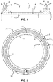
- the figure 1 represents a sectional view of a torus support 1 according to a first embodiment of the invention.
- the support is made of non-magnetic materials such as molded rigid plastic.
- a secondary winding 5 will be wound on a carrier to provide an electrical output signal from the Rogowski sensor.
- the winding covers the entire circumference of the support, however to show the structure of the support a single turn 6 is shown on the figure 1 .
- Said support 1 comprises at least one outer recess distributed over the length or the circumference of the support body.
- Said recess 2 comprises at least two grooves 3 separated by a partition 4.
- the height of the partition 4 contributes to the definition of the section of the support and prevents the winding wire is crushed in the groove during handling of the torus.
- Said grooves are in particular empty spaces used to locate the withdrawal of the plastic material during the molding operation in an area that does not affect the section of the turns.
- the grooves eliminate the shrinkage effect of the plastic material after molding. With this recess, the dimensional variations between the molding phase and the finished product phase are very small.
- the shape of the section may be oval, round but preferably with four faces corresponding to the sides of a quadrilateral. This form facilitates the handling of the torus by an operator when mounting the sensor in its protective housing and prevents crushing of the winding wire of the secondary winding.
- the corners of the quadrilateral are rounded to facilitate the winding of the wire on the support.
- the support section having a quadrilateral shape with rounded corners, said support has an inner face 7, an outer face 8, and two side faces 9 and 10 of the sensor.
- At least one of the faces of the support of the sensor comprises said recess comprising at least two grooves 3 separated by a partition 4.
- at least one of the two lateral faces of the sensor support has at least two grooves separated by a partition.
- the grooves are on the lateral face 9.
- the two lateral faces 9 and 10 of the sensor support comprise at least two grooves 3 separated by a partition 4.
- the figure 3 shows a sectional view of a torus support according to a second embodiment of the invention having grooves on the two lateral faces 9 and 10.
- figures 4 and 5 represent perspective views of the support according to the second embodiment of the invention.
- the support also comprises a stud 12 provided to maintain the terminations of the secondary winding 5 when it is wound on the support 1.
- said section of the support 1 in the form of quadrilateral has a substantially trapezoidal shape with rounded corners.
- the particular trapezoidal shape makes it possible to optimize the surface of the turn taking into account the implantation of the torus in a circuit breaker.
- the side faces 9 and 10 are preferably parallel.
- the inner face and the outer face of the trapezoidal shaped support form a right angle A or B of 90 degrees plus or minus 8 to 20 degrees with respect to the lateral faces 9 and 10.
- the section of the trapezoidal toroid support with an angle between 5 ° and 20 ° allows to obtain the largest possible turn surface given mechanical stresses.
- the view from above of the support represented on the figure 2 shows the two grooves 3 and the partition 4 present along the support of the torus on one of the lateral faces 9.
- the support comprises reinforcements 11 distributed along the grooves 3 to maintain the partition 4.
- a sensor according to the invention has preferably a support consisting of an amorphous resin with a glass transition temperature (Tg) greater than 200 ° C.
- Tg glass transition temperature
- the amorphous feature substantially reduces mold shrinkage and promotes better dimensional control of the molded part.
- CLTE Linear Thermal Expansion Coefficient of Thermal Expansion in English
- said support resin is loaded with beads or glass fibers smaller than 200 .mu.m.
- the charge or reinforcement of the material makes it possible to reduce the coefficient of linear thermal expansion CLTE to reach a value close to that of the copper used for the winding of the secondary winding.
- the beads or glass fibers will be ultra-short of the order of 50 .mu.m to 100 .mu.m. They will thus make it possible to obtain a linear coefficient of thermal expansion CLTE quasi isotropic of the part whatever the direction.
- said resin is loaded between 20 and 50%, with a particular preference around 30%.
- the figure 6 represents a diagram of an electric circuit breaker 20 comprising a sensor 20 according to one embodiment of the invention associated with a measuring and protection device.
- the electric circuit breaker 20 comprises at least one main contact 13 for cutting a current I in an electric circuit, a mechanism 14 for controlling the opening of said electrical contact 13 and a measurement and protection device for providing a control signal D auditing.
- control mechanism 14 The circuit breaker also comprises electrical power terminals 16 for connecting external electrical conductors and conductors 17 of internal connections between the main contact 13 and the terminals 16.
- At least one current sensor 21 as described above is arranged around a primary conductor 17 of the circuit breaker such as a connecting conductor 17 between a terminal 16 and a main contact 13.
- the current sensor 21 is connected to a processing unit 18 of the measuring and protection device 15 to provide representative signals Ie of an electric current flowing in the primary conductor I.
- the processing unit receives signals representative of electric current of the sensor 21, performs the processing of the current signals, performs the protection functions and signaling and if necessary provided a signal or a trip command D to the mechanism 14 to open the contacts 13 of the circuit breaker.
- the sensor 21 has a support 1 according to the second embodiment of the invention with recesses on the side faces 9 and 10. Each recess comprising two grooves 3 and a partition 4.
- the secondary winding 5 is connected to an input of the processing unit 18 to provide the current measurement signal Ie.
- the processing unit can also receive a voltage measurement signal Ve from the primary conductor 17. In this case the processing unit can also process and calculate the energy and / or the electrical power with a very high voltage. high accuracy.
- each protected pole comprises a current sensor as defined above.
- the measuring and protection device 15 comprising the sensor 21 and the processing unit 18 may be an electronic trip unit for a circuit breaker but also a relay or a module for protecting and / or measuring power and / or electrical energy. .
Landscapes
- Physics & Mathematics (AREA)
- General Physics & Mathematics (AREA)
- Engineering & Computer Science (AREA)
- Power Engineering (AREA)
- Measuring Instrument Details And Bridges, And Automatic Balancing Devices (AREA)
- Distribution Board (AREA)
- Transformers For Measuring Instruments (AREA)
Applications Claiming Priority (1)
| Application Number | Priority Date | Filing Date | Title |
|---|---|---|---|
| FR1562390A FR3045159B1 (fr) | 2015-12-15 | 2015-12-15 | Capteur de mesure de courant de type tore de rogowski, dispositif de mesure et de protection et disjoncteur electrique comportant un tel capteur |
Publications (2)
| Publication Number | Publication Date |
|---|---|
| EP3182143A1 true EP3182143A1 (de) | 2017-06-21 |
| EP3182143B1 EP3182143B1 (de) | 2020-01-01 |
Family
ID=55182463
Family Applications (1)
| Application Number | Title | Priority Date | Filing Date |
|---|---|---|---|
| EP16199248.2A Active EP3182143B1 (de) | 2015-12-15 | 2016-11-17 | Rogowski-stromsensor, schutz- und messvorrichtung, und elektrischer schutzschalter mit solcher messvorrichtung |
Country Status (8)
| Country | Link |
|---|---|
| US (1) | US10333289B2 (de) |
| EP (1) | EP3182143B1 (de) |
| CN (1) | CN107015045B (de) |
| AU (1) | AU2016273859B2 (de) |
| BR (1) | BR102016028917B1 (de) |
| ES (1) | ES2775473T3 (de) |
| FR (1) | FR3045159B1 (de) |
| RU (1) | RU2756486C2 (de) |
Families Citing this family (3)
| Publication number | Priority date | Publication date | Assignee | Title |
|---|---|---|---|---|
| US20190310289A1 (en) * | 2018-04-06 | 2019-10-10 | Eaton Intelligent Power Limited | Temperature stable rogowski coil |
| CN111175558A (zh) * | 2019-09-10 | 2020-05-19 | 上海嘉益电器设备有限公司 | 一种罗氏线圈传感器及其绕制方法 |
| US12571818B2 (en) | 2023-03-31 | 2026-03-10 | Schneider Electric USA, Inc. | PCB trace current sensor for energy measurement |
Citations (6)
| Publication number | Priority date | Publication date | Assignee | Title |
|---|---|---|---|---|
| US4264675A (en) * | 1978-01-12 | 1981-04-28 | Liautaud James P | High tolerance coil assembly |
| US5982265A (en) | 1995-02-09 | 1999-11-09 | Siemens Aktiengesellschaft | Current-detection coil for a current transformer |
| US20060176140A1 (en) * | 2005-02-04 | 2006-08-10 | James Kesler | Precision rogowski coil and method for manufacturing same |
| US20080007249A1 (en) * | 2006-07-06 | 2008-01-10 | Wilkerson Donovan E | Precision, temperature-compensated, shielded current measurement device |
| EP2667205A1 (de) | 2012-05-21 | 2013-11-27 | Schneider Electric Industries SAS | Mischstromsensor und Montageverfahren dieses Sensors |
| US20140132249A1 (en) | 2012-11-15 | 2014-05-15 | Schneider Electric Industries Sas | Mixed current sensor and method for fitting said sensor |
Family Cites Families (13)
| Publication number | Priority date | Publication date | Assignee | Title |
|---|---|---|---|---|
| SE417544B (sv) * | 1977-11-11 | 1981-03-23 | Saab Scania Ab | Synkroniseringsanordning for vexllada |
| JPH04279639A (ja) * | 1991-03-06 | 1992-10-05 | Nitto Denko Corp | 多孔質体 |
| FR2692074B1 (fr) * | 1992-06-05 | 1994-07-22 | Alsthom Gec | Bobine de rogowski. |
| US6133876A (en) * | 1998-03-23 | 2000-10-17 | Time Domain Corporation | System and method for position determination by impulse radio |
| FR2837619B1 (fr) * | 2002-03-22 | 2004-06-25 | Schneider Electric Ind Sa | Appareillage electrique de coupure limiteur ultrarapide |
| CN2636250Y (zh) * | 2003-04-16 | 2004-08-25 | 大连理工大学 | 一种新型印刷电路板罗氏线圈电流传感器 |
| CN101273418B (zh) * | 2005-09-30 | 2011-11-09 | 古河电气工业株式会社 | 多层绝缘电线和使用了该多层绝缘电线的变压器 |
| US20080000724A1 (en) * | 2006-06-29 | 2008-01-03 | Stlaske William G | Drain Valve |
| FR2912512B3 (fr) * | 2006-12-06 | 2009-05-29 | Mario Berton | Dispositif de mesure de grandeurs electriques pour lignes de transport d'energie. |
| US9461486B2 (en) * | 2011-07-02 | 2016-10-04 | Leonid Rozenboim | Accumulator battery monitoring over power circuit |
| RU109866U1 (ru) * | 2011-07-19 | 2011-10-27 | Закрытое акционерное общество "Инженерно-технический центр "Континуум" | Катушка роговского |
| DE102012201995A1 (de) * | 2012-02-10 | 2013-08-14 | Siemens Aktiengesellschaft | Schaltgerät, insbesondere Leistungsschalter |
| CN204302377U (zh) * | 2014-12-24 | 2015-04-29 | 常熟开关制造有限公司(原常熟开关厂) | 一种电流测量装置及智能断路器 |
-
2015
- 2015-12-15 FR FR1562390A patent/FR3045159B1/fr active Active
-
2016
- 2016-11-17 EP EP16199248.2A patent/EP3182143B1/de active Active
- 2016-11-17 ES ES16199248T patent/ES2775473T3/es active Active
- 2016-11-22 US US15/358,719 patent/US10333289B2/en active Active
- 2016-12-09 BR BR102016028917-3A patent/BR102016028917B1/pt active IP Right Grant
- 2016-12-13 AU AU2016273859A patent/AU2016273859B2/en active Active
- 2016-12-14 RU RU2016149103A patent/RU2756486C2/ru active
- 2016-12-14 CN CN201611151778.8A patent/CN107015045B/zh active Active
Patent Citations (6)
| Publication number | Priority date | Publication date | Assignee | Title |
|---|---|---|---|---|
| US4264675A (en) * | 1978-01-12 | 1981-04-28 | Liautaud James P | High tolerance coil assembly |
| US5982265A (en) | 1995-02-09 | 1999-11-09 | Siemens Aktiengesellschaft | Current-detection coil for a current transformer |
| US20060176140A1 (en) * | 2005-02-04 | 2006-08-10 | James Kesler | Precision rogowski coil and method for manufacturing same |
| US20080007249A1 (en) * | 2006-07-06 | 2008-01-10 | Wilkerson Donovan E | Precision, temperature-compensated, shielded current measurement device |
| EP2667205A1 (de) | 2012-05-21 | 2013-11-27 | Schneider Electric Industries SAS | Mischstromsensor und Montageverfahren dieses Sensors |
| US20140132249A1 (en) | 2012-11-15 | 2014-05-15 | Schneider Electric Industries Sas | Mixed current sensor and method for fitting said sensor |
Also Published As
| Publication number | Publication date |
|---|---|
| CN107015045A (zh) | 2017-08-04 |
| RU2016149103A (ru) | 2018-06-19 |
| ES2775473T3 (es) | 2020-07-27 |
| RU2016149103A3 (de) | 2020-04-10 |
| AU2016273859B2 (en) | 2018-04-26 |
| AU2016273859A1 (en) | 2017-06-29 |
| US20170170645A1 (en) | 2017-06-15 |
| FR3045159B1 (fr) | 2018-10-19 |
| CN107015045B (zh) | 2021-07-02 |
| BR102016028917B1 (pt) | 2022-11-29 |
| RU2756486C2 (ru) | 2021-09-30 |
| US10333289B2 (en) | 2019-06-25 |
| FR3045159A1 (fr) | 2017-06-16 |
| BR102016028917A2 (pt) | 2017-06-20 |
| EP3182143B1 (de) | 2020-01-01 |
Similar Documents
| Publication | Publication Date | Title |
|---|---|---|
| EP3182143B1 (de) | Rogowski-stromsensor, schutz- und messvorrichtung, und elektrischer schutzschalter mit solcher messvorrichtung | |
| Hu et al. | Broadly tunable one-way terahertz plasmonic waveguide based on nonreciprocal surface magneto plasmons | |
| EP2573872B1 (de) | Linsenantenne, die eine dielektrische, beugende Komponente umfasst, die in der Lage ist, eine Hyperfrequenzwellenfront zu formen | |
| US10326036B2 (en) | Device with a quantum well layer | |
| EP2995916B1 (de) | Oberflächen-mikrobearbeiteter infrarotsensor unter verwendung eines hoch temperaturstabilen interferometrischen absorbers | |
| Kearney et al. | Al/SiO x/Al single and multiband metamaterial absorbers for terahertz sensor applications | |
| FR3055416A1 (fr) | Capteur de mesure de courant de type tore de rogowski, dispositif de mesure et disjoncteur electrique comportant un tel capteur, et procede de bobinage d'un tel capteur | |
| FR2984009A1 (fr) | Dispositif mecanique de commutation electrique integre | |
| EP1445618A1 (de) | Vorrichtung zur Messung des fliessenden elektrischen Stromes | |
| EP2937703B1 (de) | Vorrichtung zum Messen mindestens einer elektrischen Größe eines Stroms, der in einem Elektrogerät fließen soll, und Einheit, die eine solche Vorrichtung umfasst | |
| Yon et al. | Latest improvements in microbolometer thin film packaging: paving the way for low-cost consumer applications | |
| EP2942609A1 (de) | Bolometer und Verfahren zum Messen elektromagnetischer Strahlung | |
| EP3278128B1 (de) | Isolierter gleichstrom- und spannungssensor mit geringem übersprechen | |
| EP2463885B1 (de) | Elektrischer Schutzschalter mit Strombegrenzer | |
| EP4343808A1 (de) | Nichtelektrische vorrichtung zum ersetzen eines stromsensors in einer schaltkammer eines lasttrennschalters sowie lasttrennschalter mit einer solchen nicht-elektrischen vorrichtung | |
| FR2926393A1 (fr) | Bloc de transformation d'un declencheur electronique a double passage | |
| EP4113564A1 (de) | Pyrotechnische sicherungseinheit für ein luftfahrzeug und luftfahrzeug mit einer solchen einheit | |
| Watai et al. | Terahertz metamaterial to demonstrate extremely wide range of effective refractive indices in the 0.3-THz band | |
| EP3218915A1 (de) | Elektromagnetischer aktuator und schutzschalter mit einem derartigen aktuator | |
| WO2016139403A1 (fr) | Structure antennaire omnidirectionnelle large bande | |
| EP3161850B1 (de) | Thermisch-magnetischer auslösungsmechanismus | |
| EP2256854A1 (de) | Flexible Multimembran-Wandvorrichtung für Filter und Multiplexer mit Wärmeausgleichstechnologie | |
| FR2931595A1 (fr) | Procede de dimensionnement d'un cable et de son fusible | |
| FR2991098A1 (fr) | Declencheur magnetique a seuil de declenchement ajustable, appareil de coupure de courant mettant en oeuvre le declencheur, et procede d'ajustement du seuil. | |
| Hokmabadi et al. | Polarization controllable THz stereometamaterial absorber |
Legal Events
| Date | Code | Title | Description |
|---|---|---|---|
| PUAI | Public reference made under article 153(3) epc to a published international application that has entered the european phase |
Free format text: ORIGINAL CODE: 0009012 |
|
| STAA | Information on the status of an ep patent application or granted ep patent |
Free format text: STATUS: THE APPLICATION HAS BEEN PUBLISHED |
|
| AK | Designated contracting states |
Kind code of ref document: A1 Designated state(s): AL AT BE BG CH CY CZ DE DK EE ES FI FR GB GR HR HU IE IS IT LI LT LU LV MC MK MT NL NO PL PT RO RS SE SI SK SM TR |
|
| AX | Request for extension of the european patent |
Extension state: BA ME |
|
| STAA | Information on the status of an ep patent application or granted ep patent |
Free format text: STATUS: REQUEST FOR EXAMINATION WAS MADE |
|
| 17P | Request for examination filed |
Effective date: 20170629 |
|
| RBV | Designated contracting states (corrected) |
Designated state(s): AL AT BE BG CH CY CZ DE DK EE ES FI FR GB GR HR HU IE IS IT LI LT LU LV MC MK MT NL NO PL PT RO RS SE SI SK SM TR |
|
| RIC1 | Information provided on ipc code assigned before grant |
Ipc: H02H 1/00 20060101ALI20190213BHEP Ipc: H02H 3/08 20060101ALI20190213BHEP Ipc: G01R 15/18 20060101AFI20190213BHEP |
|
| GRAP | Despatch of communication of intention to grant a patent |
Free format text: ORIGINAL CODE: EPIDOSNIGR1 |
|
| STAA | Information on the status of an ep patent application or granted ep patent |
Free format text: STATUS: GRANT OF PATENT IS INTENDED |
|
| INTG | Intention to grant announced |
Effective date: 20190325 |
|
| GRAS | Grant fee paid |
Free format text: ORIGINAL CODE: EPIDOSNIGR3 |
|
| GRAA | (expected) grant |
Free format text: ORIGINAL CODE: 0009210 |
|
| STAA | Information on the status of an ep patent application or granted ep patent |
Free format text: STATUS: THE PATENT HAS BEEN GRANTED |
|
| AK | Designated contracting states |
Kind code of ref document: B1 Designated state(s): AL AT BE BG CH CY CZ DE DK EE ES FI FR GB GR HR HU IE IS IT LI LT LU LV MC MK MT NL NO PL PT RO RS SE SI SK SM TR |
|
| REG | Reference to a national code |
Ref country code: GB Ref legal event code: FG4D Free format text: NOT ENGLISH |
|
| REG | Reference to a national code |
Ref country code: CH Ref legal event code: EP Ref country code: AT Ref legal event code: REF Ref document number: 1220446 Country of ref document: AT Kind code of ref document: T Effective date: 20200115 |
|
| REG | Reference to a national code |
Ref country code: DE Ref legal event code: R096 Ref document number: 602016027220 Country of ref document: DE |
|
| REG | Reference to a national code |
Ref country code: IE Ref legal event code: FG4D Free format text: LANGUAGE OF EP DOCUMENT: FRENCH |
|
| REG | Reference to a national code |
Ref country code: NL Ref legal event code: MP Effective date: 20200101 |
|
| REG | Reference to a national code |
Ref country code: LT Ref legal event code: MG4D |
|
| REG | Reference to a national code |
Ref country code: ES Ref legal event code: FG2A Ref document number: 2775473 Country of ref document: ES Kind code of ref document: T3 Effective date: 20200727 |
|
| PG25 | Lapsed in a contracting state [announced via postgrant information from national office to epo] |
Ref country code: FI Free format text: LAPSE BECAUSE OF FAILURE TO SUBMIT A TRANSLATION OF THE DESCRIPTION OR TO PAY THE FEE WITHIN THE PRESCRIBED TIME-LIMIT Effective date: 20200101 Ref country code: NO Free format text: LAPSE BECAUSE OF FAILURE TO SUBMIT A TRANSLATION OF THE DESCRIPTION OR TO PAY THE FEE WITHIN THE PRESCRIBED TIME-LIMIT Effective date: 20200401 Ref country code: NL Free format text: LAPSE BECAUSE OF FAILURE TO SUBMIT A TRANSLATION OF THE DESCRIPTION OR TO PAY THE FEE WITHIN THE PRESCRIBED TIME-LIMIT Effective date: 20200101 Ref country code: CZ Free format text: LAPSE BECAUSE OF FAILURE TO SUBMIT A TRANSLATION OF THE DESCRIPTION OR TO PAY THE FEE WITHIN THE PRESCRIBED TIME-LIMIT Effective date: 20200101 Ref country code: PT Free format text: LAPSE BECAUSE OF FAILURE TO SUBMIT A TRANSLATION OF THE DESCRIPTION OR TO PAY THE FEE WITHIN THE PRESCRIBED TIME-LIMIT Effective date: 20200527 Ref country code: LT Free format text: LAPSE BECAUSE OF FAILURE TO SUBMIT A TRANSLATION OF THE DESCRIPTION OR TO PAY THE FEE WITHIN THE PRESCRIBED TIME-LIMIT Effective date: 20200101 Ref country code: RS Free format text: LAPSE BECAUSE OF FAILURE TO SUBMIT A TRANSLATION OF THE DESCRIPTION OR TO PAY THE FEE WITHIN THE PRESCRIBED TIME-LIMIT Effective date: 20200101 |
|
| PG25 | Lapsed in a contracting state [announced via postgrant information from national office to epo] |
Ref country code: HR Free format text: LAPSE BECAUSE OF FAILURE TO SUBMIT A TRANSLATION OF THE DESCRIPTION OR TO PAY THE FEE WITHIN THE PRESCRIBED TIME-LIMIT Effective date: 20200101 Ref country code: LV Free format text: LAPSE BECAUSE OF FAILURE TO SUBMIT A TRANSLATION OF THE DESCRIPTION OR TO PAY THE FEE WITHIN THE PRESCRIBED TIME-LIMIT Effective date: 20200101 Ref country code: SE Free format text: LAPSE BECAUSE OF FAILURE TO SUBMIT A TRANSLATION OF THE DESCRIPTION OR TO PAY THE FEE WITHIN THE PRESCRIBED TIME-LIMIT Effective date: 20200101 Ref country code: GR Free format text: LAPSE BECAUSE OF FAILURE TO SUBMIT A TRANSLATION OF THE DESCRIPTION OR TO PAY THE FEE WITHIN THE PRESCRIBED TIME-LIMIT Effective date: 20200402 Ref country code: IS Free format text: LAPSE BECAUSE OF FAILURE TO SUBMIT A TRANSLATION OF THE DESCRIPTION OR TO PAY THE FEE WITHIN THE PRESCRIBED TIME-LIMIT Effective date: 20200501 Ref country code: BG Free format text: LAPSE BECAUSE OF FAILURE TO SUBMIT A TRANSLATION OF THE DESCRIPTION OR TO PAY THE FEE WITHIN THE PRESCRIBED TIME-LIMIT Effective date: 20200401 |
|
| REG | Reference to a national code |
Ref country code: DE Ref legal event code: R097 Ref document number: 602016027220 Country of ref document: DE |
|
| PG25 | Lapsed in a contracting state [announced via postgrant information from national office to epo] |
Ref country code: RO Free format text: LAPSE BECAUSE OF FAILURE TO SUBMIT A TRANSLATION OF THE DESCRIPTION OR TO PAY THE FEE WITHIN THE PRESCRIBED TIME-LIMIT Effective date: 20200101 Ref country code: DK Free format text: LAPSE BECAUSE OF FAILURE TO SUBMIT A TRANSLATION OF THE DESCRIPTION OR TO PAY THE FEE WITHIN THE PRESCRIBED TIME-LIMIT Effective date: 20200101 Ref country code: SM Free format text: LAPSE BECAUSE OF FAILURE TO SUBMIT A TRANSLATION OF THE DESCRIPTION OR TO PAY THE FEE WITHIN THE PRESCRIBED TIME-LIMIT Effective date: 20200101 Ref country code: EE Free format text: LAPSE BECAUSE OF FAILURE TO SUBMIT A TRANSLATION OF THE DESCRIPTION OR TO PAY THE FEE WITHIN THE PRESCRIBED TIME-LIMIT Effective date: 20200101 Ref country code: SK Free format text: LAPSE BECAUSE OF FAILURE TO SUBMIT A TRANSLATION OF THE DESCRIPTION OR TO PAY THE FEE WITHIN THE PRESCRIBED TIME-LIMIT Effective date: 20200101 |
|
| PLBE | No opposition filed within time limit |
Free format text: ORIGINAL CODE: 0009261 |
|
| STAA | Information on the status of an ep patent application or granted ep patent |
Free format text: STATUS: NO OPPOSITION FILED WITHIN TIME LIMIT |
|
| REG | Reference to a national code |
Ref country code: AT Ref legal event code: MK05 Ref document number: 1220446 Country of ref document: AT Kind code of ref document: T Effective date: 20200101 |
|
| 26N | No opposition filed |
Effective date: 20201002 |
|
| PG25 | Lapsed in a contracting state [announced via postgrant information from national office to epo] |
Ref country code: AT Free format text: LAPSE BECAUSE OF FAILURE TO SUBMIT A TRANSLATION OF THE DESCRIPTION OR TO PAY THE FEE WITHIN THE PRESCRIBED TIME-LIMIT Effective date: 20200101 |
|
| PG25 | Lapsed in a contracting state [announced via postgrant information from national office to epo] |
Ref country code: PL Free format text: LAPSE BECAUSE OF FAILURE TO SUBMIT A TRANSLATION OF THE DESCRIPTION OR TO PAY THE FEE WITHIN THE PRESCRIBED TIME-LIMIT Effective date: 20200101 Ref country code: SI Free format text: LAPSE BECAUSE OF FAILURE TO SUBMIT A TRANSLATION OF THE DESCRIPTION OR TO PAY THE FEE WITHIN THE PRESCRIBED TIME-LIMIT Effective date: 20200101 |
|
| PG25 | Lapsed in a contracting state [announced via postgrant information from national office to epo] |
Ref country code: MC Free format text: LAPSE BECAUSE OF FAILURE TO SUBMIT A TRANSLATION OF THE DESCRIPTION OR TO PAY THE FEE WITHIN THE PRESCRIBED TIME-LIMIT Effective date: 20200101 |
|
| REG | Reference to a national code |
Ref country code: CH Ref legal event code: PL |
|
| PG25 | Lapsed in a contracting state [announced via postgrant information from national office to epo] |
Ref country code: LU Free format text: LAPSE BECAUSE OF NON-PAYMENT OF DUE FEES Effective date: 20201117 |
|
| REG | Reference to a national code |
Ref country code: BE Ref legal event code: MM Effective date: 20201130 |
|
| PG25 | Lapsed in a contracting state [announced via postgrant information from national office to epo] |
Ref country code: CH Free format text: LAPSE BECAUSE OF NON-PAYMENT OF DUE FEES Effective date: 20201130 Ref country code: LI Free format text: LAPSE BECAUSE OF NON-PAYMENT OF DUE FEES Effective date: 20201130 |
|
| PG25 | Lapsed in a contracting state [announced via postgrant information from national office to epo] |
Ref country code: IE Free format text: LAPSE BECAUSE OF NON-PAYMENT OF DUE FEES Effective date: 20201117 |
|
| PG25 | Lapsed in a contracting state [announced via postgrant information from national office to epo] |
Ref country code: TR Free format text: LAPSE BECAUSE OF FAILURE TO SUBMIT A TRANSLATION OF THE DESCRIPTION OR TO PAY THE FEE WITHIN THE PRESCRIBED TIME-LIMIT Effective date: 20200101 Ref country code: MT Free format text: LAPSE BECAUSE OF FAILURE TO SUBMIT A TRANSLATION OF THE DESCRIPTION OR TO PAY THE FEE WITHIN THE PRESCRIBED TIME-LIMIT Effective date: 20200101 Ref country code: CY Free format text: LAPSE BECAUSE OF FAILURE TO SUBMIT A TRANSLATION OF THE DESCRIPTION OR TO PAY THE FEE WITHIN THE PRESCRIBED TIME-LIMIT Effective date: 20200101 |
|
| PG25 | Lapsed in a contracting state [announced via postgrant information from national office to epo] |
Ref country code: MK Free format text: LAPSE BECAUSE OF FAILURE TO SUBMIT A TRANSLATION OF THE DESCRIPTION OR TO PAY THE FEE WITHIN THE PRESCRIBED TIME-LIMIT Effective date: 20200101 Ref country code: AL Free format text: LAPSE BECAUSE OF FAILURE TO SUBMIT A TRANSLATION OF THE DESCRIPTION OR TO PAY THE FEE WITHIN THE PRESCRIBED TIME-LIMIT Effective date: 20200101 |
|
| PG25 | Lapsed in a contracting state [announced via postgrant information from national office to epo] |
Ref country code: BE Free format text: LAPSE BECAUSE OF NON-PAYMENT OF DUE FEES Effective date: 20201130 |
|
| PGFP | Annual fee paid to national office [announced via postgrant information from national office to epo] |
Ref country code: DE Payment date: 20251126 Year of fee payment: 10 |
|
| PGFP | Annual fee paid to national office [announced via postgrant information from national office to epo] |
Ref country code: GB Payment date: 20251125 Year of fee payment: 10 |
|
| PGFP | Annual fee paid to national office [announced via postgrant information from national office to epo] |
Ref country code: IT Payment date: 20251218 Year of fee payment: 10 |
|
| PGFP | Annual fee paid to national office [announced via postgrant information from national office to epo] |
Ref country code: FR Payment date: 20251124 Year of fee payment: 10 |
|
| PGFP | Annual fee paid to national office [announced via postgrant information from national office to epo] |
Ref country code: ES Payment date: 20251211 Year of fee payment: 10 |