EP3182146B1 - Elektronische vorrichtung, system und verfahren für isolierungswiderstandsmessungen mit funktionen zur selbstdiagnose und diagnose von isolierungsverlust bezüglich der erdung einer unter spannung stehenden, elektrischen vorrichtung - Google Patents
Elektronische vorrichtung, system und verfahren für isolierungswiderstandsmessungen mit funktionen zur selbstdiagnose und diagnose von isolierungsverlust bezüglich der erdung einer unter spannung stehenden, elektrischen vorrichtung Download PDFInfo
- Publication number
- EP3182146B1 EP3182146B1 EP16203868.1A EP16203868A EP3182146B1 EP 3182146 B1 EP3182146 B1 EP 3182146B1 EP 16203868 A EP16203868 A EP 16203868A EP 3182146 B1 EP3182146 B1 EP 3182146B1
- Authority
- EP
- European Patent Office
- Prior art keywords
- minus
- plus
- detection voltage
- value
- resistance
- Prior art date
- Legal status (The legal status is an assumption and is not a legal conclusion. Google has not performed a legal analysis and makes no representation as to the accuracy of the status listed.)
- Active
Links
Images



Classifications
-
- G—PHYSICS
- G01—MEASURING; TESTING
- G01R—MEASURING ELECTRIC VARIABLES; MEASURING MAGNETIC VARIABLES
- G01R27/00—Arrangements for measuring resistance, reactance, impedance, or electric characteristics derived therefrom
- G01R27/02—Measuring real or complex resistance, reactance, impedance, or other two-pole characteristics derived therefrom, e.g. time constant
- G01R27/16—Measuring impedance of element or network through which a current is passing from another source, e.g. cable, power line
- G01R27/18—Measuring resistance to earth, i.e. line to ground
-
- G—PHYSICS
- G01—MEASURING; TESTING
- G01R—MEASURING ELECTRIC VARIABLES; MEASURING MAGNETIC VARIABLES
- G01R31/00—Arrangements for testing electric properties; Arrangements for locating electric faults; Arrangements for electrical testing characterised by what is being tested not provided for elsewhere
- G01R31/50—Testing of electric apparatus, lines, cables or components for short-circuits, continuity, leakage current or incorrect line connections
- G01R31/52—Testing for short-circuits, leakage current or ground faults
-
- G—PHYSICS
- G01—MEASURING; TESTING
- G01R—MEASURING ELECTRIC VARIABLES; MEASURING MAGNETIC VARIABLES
- G01R19/00—Arrangements for measuring currents or voltages or for indicating presence or sign thereof
- G01R19/165—Indicating that current or voltage is either above or below a predetermined value or within or outside a predetermined range of values
- G01R19/16566—Circuits and arrangements for comparing voltage or current with one or several thresholds and for indicating the result not covered by subgroups G01R19/16504, G01R19/16528, G01R19/16533
-
- G—PHYSICS
- G01—MEASURING; TESTING
- G01R—MEASURING ELECTRIC VARIABLES; MEASURING MAGNETIC VARIABLES
- G01R27/00—Arrangements for measuring resistance, reactance, impedance, or electric characteristics derived therefrom
- G01R27/02—Measuring real or complex resistance, reactance, impedance, or other two-pole characteristics derived therefrom, e.g. time constant
- G01R27/26—Measuring inductance or capacitance; Measuring quality factor, e.g. by using the resonance method; Measuring loss factor; Measuring dielectric constants ; Measuring impedance or related variables
- G01R27/2688—Measuring quality factor or dielectric loss, e.g. loss angle, or power factor
- G01R27/2694—Measuring dielectric loss, e.g. loss angle, loss factor or power factor
-
- G—PHYSICS
- G01—MEASURING; TESTING
- G01R—MEASURING ELECTRIC VARIABLES; MEASURING MAGNETIC VARIABLES
- G01R31/00—Arrangements for testing electric properties; Arrangements for locating electric faults; Arrangements for electrical testing characterised by what is being tested not provided for elsewhere
- G01R31/005—Testing of electric installations on transport means
- G01R31/006—Testing of electric installations on transport means on road vehicles, e.g. automobiles or trucks
-
- G—PHYSICS
- G01—MEASURING; TESTING
- G01R—MEASURING ELECTRIC VARIABLES; MEASURING MAGNETIC VARIABLES
- G01R31/00—Arrangements for testing electric properties; Arrangements for locating electric faults; Arrangements for electrical testing characterised by what is being tested not provided for elsewhere
- G01R31/12—Testing dielectric strength or breakdown voltage ; Testing or monitoring effectiveness or level of insulation, e.g. of a cable or of an apparatus, for example using partial discharge measurements; Electrostatic testing
-
- G—PHYSICS
- G01—MEASURING; TESTING
- G01R—MEASURING ELECTRIC VARIABLES; MEASURING MAGNETIC VARIABLES
- G01R31/00—Arrangements for testing electric properties; Arrangements for locating electric faults; Arrangements for electrical testing characterised by what is being tested not provided for elsewhere
- G01R31/36—Arrangements for testing, measuring or monitoring the electrical condition of accumulators or electric batteries, e.g. capacity or state of charge [SoC]
- G01R31/382—Arrangements for monitoring battery or accumulator variables, e.g. SoC
-
- G—PHYSICS
- G01—MEASURING; TESTING
- G01N—INVESTIGATING OR ANALYSING MATERIALS BY DETERMINING THEIR CHEMICAL OR PHYSICAL PROPERTIES
- G01N1/00—Sampling; Preparing specimens for investigation
-
- G—PHYSICS
- G01—MEASURING; TESTING
- G01N—INVESTIGATING OR ANALYSING MATERIALS BY DETERMINING THEIR CHEMICAL OR PHYSICAL PROPERTIES
- G01N2201/00—Features of devices classified in G01N21/00
-
- G—PHYSICS
- G07—CHECKING-DEVICES
- G07C—TIME OR ATTENDANCE REGISTERS; REGISTERING OR INDICATING THE WORKING OF MACHINES; GENERATING RANDOM NUMBERS; VOTING OR LOTTERY APPARATUS; ARRANGEMENTS, SYSTEMS OR APPARATUS FOR CHECKING NOT PROVIDED FOR ELSEWHERE
- G07C5/00—Registering or indicating the working of vehicles
- G07C5/08—Registering or indicating performance data other than driving, working, idle, or waiting time, with or without registering driving, working, idle or waiting time
- G07C5/0808—Diagnosing performance data
-
- H—ELECTRICITY
- H01—ELECTRIC ELEMENTS
- H01G—CAPACITORS; CAPACITORS, RECTIFIERS, DETECTORS, SWITCHING DEVICES, LIGHT-SENSITIVE OR TEMPERATURE-SENSITIVE DEVICES OF THE ELECTROLYTIC TYPE
- H01G2/00—Details of capacitors not covered by a single one of groups H01G4/00-H01G11/00
Definitions
- the present invention relates to a device, a system and a method for measuring the insulation resistance of an energized electrical apparatus with respect to ground, and therefore also for a diagnosis of insulation loss of such an apparatus.
- the present invention also relates to a self-diagnosis method of the above device.
- insulation loss of the battery voltage with respect to the earth or to a generic reference or safety ground is one of the faults which may occur most frequently.
- a drastic decrease of the insulation resistance is generated between the high-voltage circuit and the vehicle body.
- Such a decrease in the insulation resistance can be diagnosed by means of an electronic circuit, also of known type, which is capable of detecting the insulation resistance.
- the desired functionality of automatically performing the insulation resistance measurement poses the significant technical problem of succeeding in discriminating whether, with respect to an anomalous measurement of the insulation resistance, this is due to a fault of insulation loss of the battery with respect to the ground or to a fault of the insulation resistance measurement circuit itself.
- the need is strongly felt for the insulation resistance measurement circuit or system to have effective self-diagnosis functionalities adapted to avoid that a fault in the circuit may compromise the correct detection of the insulation loss. Additionally, there is an ever-increasing need for accuracy in the measurement of insulation resistance in order to provide accurate information to the battery management system and to render the subsequent safety and protection procedures more timely and effective.
- the device for measuring the insulation resistance of the present invention provides a solution both to the problem of the accurate measurement of the insulation resistance and to the problem of the self-diagnosis of the device itself, without resorting to costly redundant measurement circuits.
- the device of the invention provides a "dynamic" type measurement (and not a “static” type measurement, as in known solutions) based on a particular switching technique capable of detecting deterioration or breakdown problems of the device itself in a more effective manner.
- the aforesaid device, system, measurement method and self-diagnosis method may be mainly employed within the "automotive" scope, for example in motion systems for an electric traction or hybrid vehicle with a class B battery (from 60 V DC to 1500 V DC).
- a system according to the invention employing the aforesaid device, is defined in claim 7.
- a method for measuring an insulation resistance according to the invention is defined in claim 13.
- a method for diagnosing an insulation loss employing the aforesaid measurement method is defined in claim 17.
- a self-diagnosis method of a device according to the invention is defined in claim 18.
- an electronic device 1 for the diagnosis of the insulation loss with respect to a ground 3, of an energized electrical apparatus 2 having a negative terminal 21 and a positive terminal 22, through the measurement of the insulation resistance RI minus referring to the negative terminal 21, that is present between the negative terminal 21 and ground 3 of apparatus 2, and of the insulation resistance RI plus referring to the positive terminal 22, that is present between the positive terminal 22 and ground 3 of apparatus 2.
- insulation resistances RI minus and RI plus are parasitic resistances: indeed, under ideal conditions, the insulation resistances between terminals of the energized electrical apparatus 2 and ground 3 should be virtually infinite value resistances.
- the energized electrical apparatus 2 with which the device is associated is, in a preferred application example, a battery 2 for electric or hybrid motor, in the automotive field.
- a battery 2 for electric or hybrid motor in the automotive field.
- such an apparatus may be any other system (such as for example, an inverter, again in the automotive field, or an electric apparatus used in any other field) which is energized with respect to earth or to a generic reference or safety ground.
- Device 1 comprises a first device terminal 11 and a second device terminal 12, adapted to be connected to the negative 21 and positive 22 terminals, respectively, of the energized electrical apparatus 2. Moreover, device 1 comprises a first resistance-switch group 13, a second resistance-switch group 14, a first measurement circuit 15, arranged between the first device terminal 11 and the ground 3 in parallel to the first resistance-switch group 13, and a second measurement circuit 16, arranged between the second device terminal 12 and the ground 3 in parallel to the second resistance-switch group 14.
- the first resistance-switch group 13 comprises a first sample resistance RS minus adapted to be connected or disconnected in a controlled manner between the first device terminal 11 and the ground 3 by means of a first sample resistance input switch S minus .
- the second resistance-switch group 14 comprises a second sample resistance RS plus adapted to be connected or disconnected in a controlled manner between the second device terminal 12 and the ground 3 by means of a second sample resistance input switch S plus .
- the first measurement circuit 15 in turn comprises a first detection circuit 150, a first charge modulation circuit 151 and a first partition resistor RB minus connected between the first device terminal 11 and the first detection circuit 150, so that the first partition resistor RB minus and the first detection circuit 150 are arranged mutually in series.
- the first detection circuit 150 comprises at least a first resistor R2 and a first capacitor C1 arranged mutually in parallel, so that at the ends of the first capacitor C1, when the first device terminal 11 is connected to the energized electrical apparatus 2, after a transient required for the measurement to reach a first steady state, there is a first detection voltage VC minus depending on the negative voltage V minus of the energized electrical apparatus 2.
- the first detection circuit 150 further comprises a first voltage meter U minus .
- the first charge modulation circuit 151 is arranged in parallel to the first detection circuit 150 and comprises a first modulation resistance R1 and a first modulation switch SW1, which is arranged in series with the first modulation resistance R1 and is adapted to be controlled by means of a first driving signal V SW-minus , so that when the first device terminal 11 is connected to the energized electrical apparatus 2, the first capacitor C1 is partially discharged and recharged during each closing and opening period of the first modulation switch SW1, respectively, so that the first detection voltage VC minus oscillates between a first detection voltage maximum value VC minus-MAX and a first detection voltage minimum value VC minus-MIN , around a first detection voltage intermediate value VC minus representative of the negative voltage V minus of the energized electrical apparatus 2.
- the second measurement circuit 16 in turn comprises a second detection circuit 160, a second charge modulation circuit 161 and a second partition resistor RB plus connected between the second device terminal 12 and the second detection circuit 160 so that the second partition resistor RB plus and the second detection circuit 160 are arranged mutually in series.
- the second detection circuit 160 comprises at least a second resistor R6 and a second capacitor C2 arranged mutually in parallel, so that at the ends of the second capacitor C2, when the second device terminal 12 is connected to the energized electrical apparatus 2, after a transient required for the measurement to reach a second steady state, there is a second detection voltage VC plus depending on the positive voltage V plus of the energized electrical apparatus.
- the second detection circuit 160 further comprises a second voltage meter U plus .
- the second charge modulation circuit 161 is arranged in parallel to the second detection circuit 160 and comprises a second modulation resistance R5 and a second modulation switch SW2, which is arranged in series with the second modulation resistance R5 and is adapted to be controlled by a second driving signal V SW-plus , so that, when the second device terminal 12 is connected to the energized electrical apparatus 2, the second capacitor C2 is partially discharged and recharged during each closing and opening period of the second modulation switch SW2, respectively, so that the second detection voltage VC plus oscillates between a second detection voltage maximum value VC plus-MAX and a second detection voltage minimum value VC plus-MIN , around a second detection voltage intermediate value VC plus representative of the positive voltage V plus of the energized electrical apparatus 2.
- the aforesaid first voltage meter U minus is configured to provide the first detection voltage VC minus under both opening and closing conditions of the first resistance-switch group switch S minus , in which conditions the first sample resistance RS minus is connected and disconnected, respectively.
- the aforesaid second voltage meter U plus is configured to provide the second detection voltage VC plus under both opening and closing conditions of the second resistance-switch group switch S plus , in which conditions the second sample resistance RS plus is connected and disconnected, respectively.
- the device further comprises a first device switch M minus adapted to connect or disconnect in a controlled manner the first terminal of device 11 to/from the negative terminal 21 of the energized electrical apparatus 2, and a second device switch M plus adapted to connect or disconnect in a controlled manner the second terminal of device 12 to/from the positive terminal 22 of the energized electrical apparatus 2.
- each of the aforesaid first device switch M minus and second device switch M plus comprises an electromechanical switch.
- Each of the aforesaid first modulation switch SW1 and second modulation switch SW2 comprises a respective solid state electronic switch.
- the first detection circuit 150 further comprises a third resistor R3 connected between the parallel of the first resistor R2 and of the first capacitor C1 and the ground 3; and the second detection circuit 160 further comprises a fourth resistor R7 connected between the parallel of the second resistor R6 and the second capacitor C2 and the ground 3.
- the first detection circuit 150 further comprises an output resistor R4 and an output diode D1, which are connected between the output of the first voltage meter U minus and ground.
- the second detection circuit 180 further comprises an output resistor R8 and an output diode D2, which are connected between the output of the first voltage meter U plus and ground.
- the first measurement circuit 15 and the second measurement circuit 16 have an identical circuit structure and have electrical parameters of corresponding resistors and capacitors respectively identical.
- each of the aforesaid first voltage meter U minus and second voltage meter U plus comprises a respective operational amplifier.
- the aforesaid first sample resistance RS minus and second sample resistance RS plus have values which conform with the ones set forth in Standard ISO 6469.
- Figure 1 depicts (in the dashed box) the equivalent circuit of the battery pack 2 (which is not part of the device, but in this example is the energized electrical apparatus 2 to which device 1 can be connected to perform its functions).
- the two driven switches M minus and M plus can connect device 1 to the two terminals of the DC BUS when there it is required to perform the measurement of the insulation resistance, or otherwise disconnect it.
- V B indicates the voltage present between the terminals of the battery connected to the DC BUS and of which the insulation resistance with respect to a ground 3 is to be determined.
- a ground may be a safety ground, for example the chassis of the vehicle in the case of an electric vehicle, or a generic earth.
- References V plus and V minus indicate, respectively, the voltage of the positive pole and the negative pole of the battery with respect to the aforesaid ground.
- V B V plus - V minus is valid, where by convention, consistently to what is shown, V minus always has a negative sign.
- the insulation resistance of the battery pack is represented by means of two concentrated parameters, which are not known in advance, one, indicated as RI plus , referring to the positive terminal of the DC BUS, and one, indicated as RI minus , referring to the negative terminal of the DC BUS.
- CI minus and CI plus are to be considered for the purposes of assessing the delays, and the presence thereof can be neglected, for the purposes of the calculations, only if the measurement acquisitions are performed after the exhaustion of the voltage transients caused by CI minus and CI plus .
- an electronic system 10 for the diagnosis of the insulation loss of an energized electrical apparatus e.g., a battery
- Such a system 10 comprises an electronic device 1 according to any one of the embodiments shown above, for the diagnosis of the insulation loss of an energized electrical apparatus, and further comprises a control device 5.
- the control device 5 is configured to generate and provide the first modulation switch SW1 with the aforesaid first driving signal V SW-minus , and to generate and provide the second modulation switch SW2 with the aforesaid second driving signal V SW-plus .
- control device 5 is configured to receive the first detection voltage VC minus from the first voltage meter U minus and the second detection voltage VC plus from the second voltage meter U plus .
- the control device 5 is also configured to determine a first value of first detection voltage VC1 minus , under condition of disconnection of the first sample resistance RS minus , and to determine a second value of first detection voltage VC2 minus , under condition of connection of the first sample resistance RS minus .
- the control device 5 is also configured to determine a first value of second detection voltage VC1 plus , under condition of disconnection of the second sample resistance RS plus , and to determine a second value of second detection voltage VC2 plus , under condition of connection of the second sample resistance RS plus .
- the control device 5 is also configured to calculate the negative terminal insulation resistance RI minus and the positive terminal insulation resistance RI plus of the energized electrical apparatus on the basis of the aforesaid first value of first detection voltage VC1 minus and second value of first detection voltage VC2 minus and/or of the aforesaid first value of second detection voltage VC1 plus and second value of second detection voltage VC2 plus .
- control device 5 is configured to determine the first value of first detection voltage VC1 minus on the basis of the first detection voltage maximum value VC1 minus-MAX and the first detection voltage minimum value VC1 minus-MIN , under condition of disconnection of the first sample resistance RS minus , and to determine the second value of first detection voltage VC2 minus on the basis of the first detection voltage maximum value VC2 minus-MAX and the first detection voltage minimum value VC2 minus-MIN under condition of connection of the first sample resistance RS minus .
- control device 5 is configured to determine the first value of second detection voltage VC1 plus on the basis of the second detection voltage maximum value VC1 plus-MAX and the second detection voltage minimum value VC1 plus-MIN under condition of disconnection of the second sample resistance RS plus , and to determine the second value of second detection voltage VC2 plus on the basis of the second detection voltage maximum value VC2 plus-MAX and the second detection voltage minimum value VC2 plus-MIN under condition of connection of the second sample resistance RS plus .
- the determination of the aforesaid first or second value of first or second detection voltage is performed by the control device 5 on the basis of an average of samples detected by the respective signals.
- the aforesaid first driving signal V SW-minus is a pulse signal having a first frequency, in which the presence and absence of the pulse control the closing and opening, or the opening and closing, of the first modulation switch SW1, and in which the pulse duration with respect to period T associated with a first frequency defines a first close-open duty-cycle DC1.
- the aforesaid second driving signal V SW-plus is a pulse signal having a second frequency, in which the presence and absence of the pulse control the closing and opening, or the opening and closing, of the second modulation switch SW2, and in which the pulse duration with respect to period T associated with the second frequency defines the second close-open duty-cycle DC2.
- control device 5 is further configured to dynamically adjust, during the measurement, one or any combination of the following parameters: first frequency of the first driving signal V SW-minus ; second frequency of the second driving signal V SW-plus ; first close-open duty-cycle DC1; second close-open duty-cycle (DC2).
- the first and the second driving signals V SW-minus , V SW-plus are periodic signals of Pulse Width Modulation (PWM) type; the first and the second driving frequency are equal to each other; the first close-open duty-cycle DC1 and the second close-open duty-cycle DC2 are equal to each other.
- PWM Pulse Width Modulation
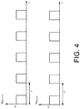
- the driving signals V SW-minus and V SW-plus are identical or derive from a same signal. Such a circumstance is depicted by way of example in figure 4 .
- the measurement device 1 uses a kind of switching technique in each of the parts thereof.
- the measurement device 1 comprises, in the example herein contemplated, the resistors RB minus , R1, R2, R3, capacitor C1, switch SW1 and an operational amplifier U minus in inverting configuration, which measures the voltage difference present at the ends of capacitor C1.
- the resistors RB minus , R1, R2, R3, capacitor C1, switch SW1 and an operational amplifier U minus in inverting configuration which measures the voltage difference present at the ends of capacitor C1.
- the measurement device 1 comprises, in the example herein considered, the resistors RB plus , R5, R6, R7, capacitor C2, switch SW2 and the operational amplifier in inverting configuration, which measures the voltage difference present at the ends of capacitor C2.
- the switches SW1 and SW2 are controlled by two driving signals of frequency type, references mentioned above, and indicated in figure 4 with numerals V SW-minus and V SW-plus .
- capacitor C1 serves to filter over time the voltage present at the ends of resistor R2; when switch SW1 is open, and therefore resistor R1 is excluded from the measurement circuit, the leakage current which crosses RB minus reaches the ground through resistance R2 and is partly intercepted by capacitor C1, which is therefore charged, thus increasing the voltage at the ends thereof.
- resistor R1 which has a significantly lower value with respect to R2, is arranged in parallel to the series consisting of R2 and R3; accordingly, the resistance of that parallel decreases and capacitor C1 starts to be discharged.
- the charging and discharging cycle of capacitor C1 repeats periodically, stabilizing around a position of equilibrium, or stationary steady state, after a given transient.
- the average voltage at the ends of capacitor C1 and of resistor R2 depends on the current which crosses resistor RB minus and on a proportionality factor which is dependent on the relative value of resistor R2 with respect to resistor R1 and R3 and on the duty-cycle with which switch SW1 is driven.
- the current which crosses resistance RB minus is in turn proportional to voltage V minus of the negative pole of the battery pack with respect to ground. Therefore, the voltage at the ends of capacitor C1 and the voltage VC minus acquired by the insulation resistance measurement system is proportional to voltage V minus .
- this may result in the proportionality factor between VC minus and V minus being dynamically varied (for example by varying the duty-cycle) according to the voltages measured, when required.
- the proportionality factor between VC minus and V minus is constant over time and cannot be changed once the measurement circuit is defined.
- the switching period of switch SW1 can be selected so as to be lower than the time constants due to the parasitic parameters present in the circuit of the battery (this is true, for example, for a switching period equal to 2 ms). Thereby, the charge and discharge of capacitor C1 has an approximately linear trend over time.
- the average value of each of the voltages VC minus and VC plus can easily be obtained, for example, by alternatively sampling the respective signal on the maximum value and on the minimum value.
- the voltages VC minus and VC plus are directly proportional to the negative and positive voltages of the battery with respect to ground. Therefore, when the measurement has stabilized, at steady-state, VC minus and VC plus also indirectly depend on the unknown value of the insulation resistances RI minus , RI plus , besides depending on the known resistances and duty-cycles of the measurement circuits.
- system 10 is configured to perform measurement methods and diagnoses, and/or to operate self-diagnosis procedures as described later.
- a method is now described for measuring the negative terminal insulation resistance RI minus , present between a negative terminal 11 and the ground 3 of an energized electrical apparatus 2, and the positive terminal insulation resistance RI plus , present between a positive terminal 12 and ground 3 of the same energized electrical apparatus 2.
- such a ground 3 is a "main" ground of the motor vehicle, for example the chassis of the motor vehicle itself.
- the method firstly comprises the steps of connecting a first measurement circuit 15 between the aforesaid negative terminal 11 and ground 3 of the energized electrical apparatus 2 to detect a first value VC1 minus of a first detection voltage VC minus , depending on the negative voltage V minus of the energized electrical apparatus 2; furthermore, connecting a second measurement circuit 16 between the aforesaid positive terminal 12 and ground 3 of the energized electrical apparatus 2 to detect a first value VC1 plus of a second detection voltage VC plus , depending on the positive voltage V plus of the energized electrical apparatus 2.
- the method comprises one of the following two alternative steps: connecting a first sample resistance RS minus in parallel to the first measurement circuit 15, between the aforesaid negative terminal 11 and ground 3; or connecting a second sample resistance RS plus in parallel to the second measurement circuit 16, between the aforesaid positive terminal 12 and ground 3.
- the method then provides detecting a second value VC2 minus of the first detection voltage VC minus and detecting a second value VC2 plus of the second detection voltage VC plus under the aforesaid connection condition of connection of one between the first sample resistance RS minus and the second sample resistance RS plus .
- the method comprises the step of calculating the negative terminal insulation resistance RI minus and the positive terminal insulation resistance RI plus of the energized electrical apparatus on the basis of the aforesaid first value of first detection voltage VC1 minus , second value of first detection voltage VC2 minus , first value of second detection voltage VC1 plus and second value of second detection voltage VC2 plus .
- the aforesaid step of detecting a first value of first detection voltage VC1 minus comprises the steps of: modulating the first detection voltage VC minus by means of a modulation signal; then detecting the modulated first detection voltage VC minus ; then determining the first value of first detection voltage VC1 minus on the basis of the modulated first detection voltage VC minus .
- the aforesaid step of detecting a first value of second detection voltage VC1 plus comprises the steps of: modulating the second detection voltage VC plus by means of a modulation signal; then detecting the modulated second detection voltage VC plus ; then determining the first value of second detection voltage VC1 plus on the basis of the modulated second detection voltage VC plus .
- the aforesaid step of detecting a second value of first detection voltage VC2 minus comprises the steps of: modulating again the first detection voltage VC minus by means of the modulation signal while the aforesaid first sample resistance RS minus or second sample resistance RS plus is connected; then detecting again the modulated first detection voltage VC minus and determining the second value of first detection voltage VC2 minus on the basis of the modulated first detection voltage VC minus detected while the aforesaid first sample resistance RS minus or second sample resistance RS plus is connected.
- the aforesaid step of detecting a second value of second detection voltage VC2 plus comprises the steps of: modulating again the second detection voltage VC plus by means of the modulation signal while the aforesaid first sample resistance RS minus or second sample resistance RS plus is connected; then detecting again the modulated second detection voltage VC plus and determining a second value of second detection voltage VC2 plus on the basis of the modulated second detection voltage VC plus detected while the aforesaid first sample resistance RS minus or second sample resistance RS plus is connected.
- the method prior to the aforesaid step of connecting the first or second sample resistance, provides comparing the first value of first detection voltage VC1 minus with the first value of second detection voltage VC plus ; if the comparison results in the first detection voltage VC minus being greater than the second detection voltage VC plus , the first sample resistance RS minus is connected; if instead the comparison results in the first detection voltage VC minus being less than the second detection voltage VC plus , the second sample resistance RS plus is connected.
- the above-described embodiment advantageously allows performing the measurement procedure which implies reaching smaller voltages in absolute value (see for example, figure 6 ), which reduces possible criticalities.
- the aforesaid step of modulating the first detection voltage VC minus comprises modulating the first detection voltage VC minus so that it oscillates between a first detection voltage maximum value VC1 minus-MAX and a first detection voltage minimum value VC1 minus-MIN .
- the aforesaid the step of modulating again the first detection voltage VC minus comprises modulating again the first detection voltage VC minus so that it oscillates between a new first detection voltage maximum value VC2 minus-MAX and a new first detection voltage minimum value VC2 minus-MIN .
- the aforesaid step of modulating the second detection voltage VC plus comprises modulating the second detection voltage VC plus so that it oscillates between a second detection voltage maximum value VC1 plus-MAX and a second detection voltage minimum value VC1 plus-MIN .
- the aforesaid step of modulating again the second detection voltage VC plus comprises modulating the second detection voltage VC plus so that it oscillates between a new second detection voltage maximum value VC2 plus-MAX and a new second detection voltage minimum value VC2 plus-MIN .
- insulation resistance measurement method described above provides various implementing options concerning how to perform the steps of detecting the first or second detection voltage and of determining the first and the second value of such a first or second detection voltage.
- the aforesaid step of detecting a modulated first detection voltage VC minus comprises measuring the first detection voltage maximum value VC1 minus-MAX and the first detection voltage minimum value VC1 minus-MIN ; and determining a first value of first detection voltage VC1 minus on the basis of the first detection voltage maximum value VC1 minus-MAX and the first detection voltage minimum value VC1 minus-MIN .
- the aforesaid step of detecting again a modulated first detection voltage VC minus comprises measuring the first detection voltage maximum value VC2 minus-MAX and the first detection voltage minimum value VC2 minus-MIN while the first sample resistance RS minus or the second sample resistance RS plus is connected, and then determining a second value of first detection voltage VC2 minus on the basis of said first detection voltage maximum value VC2 minus-MAX and first detection voltage minimum value VC2 minus-MIN detected while the first sample resistance RS minus or the second sample resistance RS plus is connected.
- the aforesaid step of detecting a second detection voltage VC plus comprises measuring the second detection voltage maximum value VC1 plus-MAX and the second detection voltage minimum value VC1 plus-MIN , and determining a first value of second detection voltage VC1 plus on the basis of the second detection voltage maximum value VC1 plus-MAX and the second detection voltage minimum value VC1 plus-MIN .
- the aforesaid step of detecting again a modulated second detection voltage VC plus comprises measuring the second detection voltage maximum value VC2 plus-MAX and the second detection voltage minimum value VC2 plus-MIN while the first sample resistance RS minus or the second sample resistance RS plus is connected; and then determining a second value of second detection voltage VC2 plus on the basis of said second detection voltage maximum value VC2 plus-MAX and second detection voltage minimum value VC2 plus-MIN detected while the first sample resistance RS minus or the second sample resistance RS plus is connected.
- the aforesaid steps of detecting a first or a second detection voltage comprise detecting a sequence of samples of the modulated first or second detection voltage; and the successive steps of determining a first or second value of first or second detection voltage comprise determining an average value of the samples respectively detected.
- the aforesaid measurements are performed in a stationary steady state, i.e., after a settlement time following the transient occurring each time branches of the circuit are connected or disconnected.
- the measurement of the detected signal samples also may be employed to check the end of the transient or recognize the achievement of the stationary steady state.
- FIG 2 shows a portion of the "negative branch” of device 1 related to voltage V minus (similar arguments and illustrations apply to the "positive branch” of device 1 related to voltage V plus ).
- V minus and VC minus you may begin by calculating the voltage oscillation ⁇ VC minus (equal to VC1 minus-MAX - VC1 minus-MIN ) generated by the current I C1 which charges and discharges capacitor C1 due to the effect of opening and closing switch SW1 (with periods T ON and T OFF ).
- OFF ⁇ 1 C 1 I C 1 _ OFF ⁇ T OFF relation valid in the hypothesis that the charge and discharge constant of the capacitor is much greater than the times T ON and T OFF .
- I C 1 ON R 1 R 2 I 0 minus ⁇ VC minus R 1 + R 2 + R 3 R 1 R 2 + R 3
- Duty T ON / (T ON + T OFF ).
- Such a parameter corresponds to the parameters DC1 or DC2, already mentioned above.
- I 0 minus R 1 + R 2 ⁇ Duty + R 3 R 1 R 2 + R 2 R 3 1 ⁇ Duty VC minus
- V minus RB minus I 0 minus + V 0 minus
- V _ minus _ on I 0 minus R 1 R 3 + VC minus R 1 R 1 + R 3 + RB minus I 0 minus
- V minus OFF I 0 minus R 3 + VC minus + RB minus I 0 minus
- V minus Duty ⁇ V _ minus _ on + 1 ⁇ Duty ⁇ V _ minus _ off
- V _ minus I 0 minus R 1 R 3 + R 1 + 2 RB minus R 1 + R 3 + R 3 2 2 R 1 + R 3 + VC minus 2 R 1 + R 3 2 R 1 + R 3
- V _ minus VC minus 2 R 1 + 2 R 3 + R 2 R 2 2 R 1 + R 3 ⁇ 2 R 1 R 3 + R 3 2 + 2 RB minus R 1 + R 3 2 R 1 + R 3 + 2 R 1 + R 3 2 R 1 + R 3 2 R 1 + R 3
- V _ plus VC plus 2 R 5 + 2 R 7 + R 6 R 6 2 R 5 + R 7 ⁇ 2 R 5 R 7 + R 7 2 + 2 RB plus R 5 + R 7 2 R 5 + R 7 + 2 R 5 + R 7 2 R 5 + R 7
- amplifier U minus is in inverting configuration with unitary gain so as to obtain a positive quantity output with respect to the ground of the chassis. Therefore, starting from an electrical quantity V minus , which is negative with respect to the voltage of the chassis, a negative voltage VC minus at the amplifier input and a positive voltage -VC minus at the output of the same amplifier, are obtained.
- amplifier U plus is in non-inverting configuration since V plus is already positive with respect to the voltage of the chassis.
- Formula (4) shows that it is always possible to determine the value of V minus frorn the measurement of VC minus , and the value of V plus from the measurement of VC plus , and the sum of which, in absolute value, is the battery voltage V B .
- V minus and V plus it is still not possible to calculate the value of the two insulation resistances because, according to the hypotheses made, the two equations (3a) and (3b) are linearly dependent on each other.
- a further measurement is performed of V minus and of V plus after inserting in the measurement circuit at least one of the two resistors RS minus or RS plus , which value is known, by closing of the respective switches S minus or S plus .
- the value of the sample resistances RS minus and RS plus (which may be connected and disconnected to/from the negative pole and to/from the positive pole of the battery, respectively, with respect to the ground of the chassis) preferably shall conform with the provisions set out in Standard ISO 6469, while taking into consideration also the presence in parallel of the two resistances of the measurement circuit.
- the value of resistance RS minus preferably takes on a value dependent on the battery voltage V B so that the parallel of RS with RB ranges from about 100 ohm/V to about500 ohm/V.
- the voltages V minus and V plus can be unbalanced with respect to the ground and a new measurement of such voltages can be obtained with respect to the ground through the acquisition of the voltages VC minus and VC plus .
- the value of the insulation resistance of the battery can be obtained with respect to the ground of the chassis from the measurement of VC minus and of VC plus before and after the closing of one of the two switches S plus and S minus . Moreover, a more and more accurate estimate of the two insulation resistances can be obtained through the periodic acquisition of the voltages VC minus and of VC plus .
- a first acquisition of the voltages VC minus and VC plus is performed with the two switches S minus and S plus open. Then, one of the two switches S plus or S minus is closed depending on whether VC minus is greater or less than VC plus . Then, the stabilization of the two values to be acquired is awaited, and then a new acquisition is performed of the values VC minus and VC plus . After the double measurement, a first estimate of the value of the two insulation resistances RI plus and RI minus can be obtained.
- Such a procedure may be performed periodically in order to improve the precision and reliability of the measurement over time.
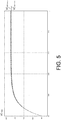
- Figure 6 shows, by way of example, the trend of the two voltages VC minus and VC plus acquired during the calculation procedure of the insulation resistances.
- RI minus > RI plus therefore in the first step, in which the two switches S plus and S minus are open, voltage VC minus is greater than VC plus .
- switch S minus being closed in the second measurement step, putting in parallel resistance RI minus to resistance RS minus , the closing of which converts the unbalancing of the two voltages, and a successive measurement is performed of the two voltages VC minus and VC plus at the end of the transient.
- the value of the two insulation resistances is obtained from the measurements obtained through the two acquisitions, through a known conversion formula, which is indicated herein below.
- Figure 6 also points out the oscillations of the two signals VC minus and VC plus , which are due to the imposed modulation, and therefore the values VC1 minus-max , VC1 minus-min , VC1 plus-max and VC1 plus-min (within which VC minus and VC plus oscillate, respectively, in the circumstance in which resistance RS minus is not connected) and the values VC2 minus-max , VC2 minus-min , VC2 plus-max and VC2 plus-min (within which VC minus and VC plus oscillate, respectively, in the circumstance in which resistance RS minus is connected), are indicated.
- RB' minus indicates the sum of resistance RB minus and of the equivalent resistance of the measurement circuit consisting of resistances R1, R2, R3 and of capacitor C1 (also affected by the control Duty of SW1):
- RB minus ′ RB minus + V 0 minus I 0 minus
- V0 minus-ON , V0 minus-OFF , and V0 minus are recalculated.
- Such a method comprises the steps of measuring a negative terminal insulation resistance RI minus , present between a negative terminal 11 and the ground 3 of the energized electrical apparatus 2, and a positive terminal insulation resistance RI plus , present between a positive terminal 12 and the ground 3 of the energized electrical apparatus; and therefore diagnosing the insulation loss of the energized electrical apparatus 2 on the basis of the negative terminal insulation resistance RI minus and the positive terminal insulation resistance RI plus which have been measured.
- the aforesaid measurement step is performed by means of an insulation resistance measurement method according to one of the embodiments shown above.
- the execution of such tests may occur according to a pre-ordered sequence, between one insulation resistance measurement and another, or according to the result of preceding tests or according to the functioning state of the system at a given moment.
- the self-diagnosis functions may comprise any subgroup of tests herein below shown, by way of example, or other similar tests: indeed, given the flexibility of the measurement circuit, it is theoretically possible to perform many different tests, some of which perfectly equivalent to one other; only the simplest or most significant tests are described here.
- the tests which may be executed are substantially "plausibility tests", which are performed under particular operating conditions of the device, and are capable of checking the correspondence or lack of correspondence between a value read and a respective value expected.
- the measurement device When the two device switches instead are closed, the measurement device is connected to the battery and it is supplied; therefore, the voltages VC minus and VC plus are to have values the sum of which is proportional to the battery voltage and to the duty cycle applied to the measurement device, which, in extreme cases, may also be null (when switch SW1 is always open) or unitary (when switch SW1 is always closed).
- Such a self-diagnosis in particular comprises a test for checking the integrity of the two input switches (or relays) of sample resistance S plus and S minus . Whether they are of electro-mechanical type or electronic type, these relays must support high potential differences at the ends thereof and are frequently subjected to electrical stresses which may damage them.
- the checking test may for example, consist in controlling the two input switches of sample resistance S plus and S minus sequentially in the four configurations possible and, for each one, reading the value either of VC minus or of VC plus or of both, and performing certain plausibility tests on the basis of the values read.
- the self-diagnosis test of the gain comprises a group of safety mechanisms capable of detecting faults which may result in an incorrect estimate of the battery voltage, which is partitioned in the two voltages VC plus and VC minus referring to the ground, the occurrence of any condition which modifies the gain of the measurement circuit (for example, a variation of the resistances RB minus or RB plus or a gain error of the amplifiers U minus or U plus ).
- Such a test may provide for example comparing the value of voltage V B acquired through the insulation measurement device with respect to the direct measurement of the battery voltage V B , which is a piece of information available through other measurement circuits.
- Such a self-diagnosis comprise a series of elementary tests, which may be performed ad hoc or also during the normal functioning of the system.
- elementary tests are consistency tests which provide measuring both the absolute values of the signals V plus and V minus and the related modulation oscillations ⁇ VC plus and ⁇ VC minus ; then comparing such values with certain thresholds and diagnosing the main faults or anomalies which may be present in the measurement device of the insulation resistance on the basis of such comparisons.
- Such a method comprises the steps of: performing a diagnosis of the functioning of the first resistance-switch group (RS minus , S minus ) and of the second resistance-switch group (RS plus , S plus ) of the device on the basis of measurements of the first VC minus and of the second detection voltage VC plus , performed by the device under conditions in which the first sample resistance input switch S minus and the second sample resistance input switch S plus are arranged under a plurality of conditions, respectively, belonging to the following set of conditions: open, open; closed, open; open, closed; closed. closed.
- the method then provides performing a consistency test of the measurement taken by the device on the basis of the first detection voltage VC minus and the second detection voltage VC plus , as measured by the device, and of the battery voltage V B (that is the difference between the positive voltage V plus and the negative voltage V minus of the battery), the value of which is available regardless of the measurements of device 1.
- the method also provides checking the presence and measuring the amplitude of a first oscillation ⁇ VC minus of the first detection voltage VC minus around its steady state value while the first modulation switch SW1 switches between opening and closing, and further checking the presence and measuring the amplitude of a second oscillation ⁇ VC plus of the second detection voltage VC plus around its steady state value while the second modulation switch SW2 switches between opening and closing.
- the method provides performing a diagnosis of the functioning of the first measurement circuit and of the second measurement circuit of the device on the basis of measurements of the first detection voltage VC minus , the second detection voltage VC plus , the amplitude of the first oscillation ⁇ VC minus and the amplitude of the second oscillation ⁇ VC plus .
- the self-diagnosis method comprises, prior to the step of performing a diagnosis of the functioning of the first resistance-switch group 13, the further step of performing a diagnosis of the functioning of the devices switches (M minus , M plus ) on the basis of the first detection voltage VC minus and of the second detection voltage VC plus , which are measured by the device under condition of closed device switches M minus , M plus .
- the step of performing a diagnosis of the functioning of the resistance-switch groups comprises measuring the first VC minus and the second detection voltage VC plus under conditions in which the first sample resistance input switch S minus and the second sample resistance input switch S plus are arranged, respectively, under the following conditions: open, open; closed, open; open, closed; closed, closed.
- the step of performing a diagnosis of the functioning of the resistance-switch groups 13, 14 comprises the following first, second, third and fourth tests.
- the first test comprises opening the first sample resistance input switch S minus and the second sample resistance input switch S plus , measuring the first VC minus and the second detection voltage VC plus after reaching a steady state condition; then comparing the absolute value of the difference between the first and second detection voltage with a first threshold THR0, and determining a positive result of the first test if such an absolute value of the difference is less than the first threshold THR0 (in fact, a high voltage value is a symptom of an unbalancing of the two insulation resistances).
- the first test further comprises comparing the absolute value of the difference between the first and second detection voltage with a calibration threshold THRc to determine a first or a second value for the second threshold THR1 and for a third threshold THR2 (which will be employed in the successive tests), depending on whether the absolute value of the difference is higher or lower than the calibration threshold THRc.
- the second test comprises closing the first sample resistance input switch S minus and opening the second sample resistance input switch S plus after reaching a steady state condition; then measuring the first VC minus and the second detection voltage VC plus , comparing the difference between the second detection voltage VC plus and the first detection voltage VC minus with the value determined (or saved) for the second threshold THR1, and determining a positive result of the second test if such a difference is greater than the second threshold THR1.
- the third test comprises opening the first sample resistance input switch S minus and closing the second sample resistance input switch S plus , measuring the first VC minus and the second detection voltage VC plus , comparing the difference between the first detection voltage VC minus and the second detection voltage VC plus with the value determined (or saved) for the second threshold THR1, and determining a positive result of the third test if such a difference is greater than the second threshold THR1.
- the fourth test comprises closing the first sample resistance input switch S minus and the second sample resistance input switch S plus , measuring the first VC minus and the second detection voltage VC plus , comparing the absolute value of the difference between the first and the second detection voltage with the value determined (or saved) for the third threshold THR2 and determining a positive result of the fourth test if such an absolute value of the difference is less than the third threshold THR2.
- the method finally provides diagnosing a correct functioning of the resistance-switch groups if all the four tests shown above provide a positive result.
- diagnosis of functioning of the resistance-switch groups may be performed in various manners. For example, according to an option alternative to the preceding one, such a diagnosis may be performed in the following manner.
- the input switches of sample resistance S minus and S plus initially are open (while the switching switches SW1 and SW2 may be indifferently open or closed or in the step of switching).
- the voltages VC minus and VC plus are measured under such conditions.
- any one between S minus and S plus is closed and a check is made whether the respective insertion of the sample resistance RS minus or RS plus generates the unbalancing expected on the voltages VC minus and VC plus .
- the step of performing a consistency test of the measurement taken by the device comprises: calculating the sum of the first detection voltage VC minus and of the second detection voltage VC plus ; storing the difference between the positive V plus and negative V minus voltage of the battery, on the basis of the battery voltage V B (which is precisely the difference between the positive voltage and the negative voltage of the battery) which is known independently on the measurements of the device (for example, known to a battery management system BMS of higher level); then calculating a comparison value by weighing the battery voltage with a factor (A) dependent on the electrical parameters of the device; finally, determining a positive result of the consistency test if the aforesaid sum of the first detection voltage VC minus and the second detection voltage VC plus differs from the aforesaid comparison value by less than a predefined amount.
- the step of checking the presence and measuring the amplitude of a first and a second oscillation comprises: switching the first modulation switch SW1 between opening and closing, by the first driving signal; then measuring the first detection voltage maximum value VC minus-MAX and the first detection voltage minimum value VC minus-MIN and calculating the difference between such maximum value and minimum value of first detection voltage to determine the first oscillation amplitude ⁇ VC minus .
- the step of performing a diagnosis of the functioning of the first (15) and second measurement circuit (16) comprises: identifying a first group of possible faults of the first measurement circuit 15 if the first detection voltage VC minus is lower than a low threshold (VTHRL); identifying a second group of possible faults of the first measurement circuit 15 if the first detection voltage VC minus is higher than a first high threshold VTHR-H1; identifying a third group of possible faults of the first measurement circuit 15 if the amplitude of the first oscillation ⁇ VC minus is lower than a low threshold VTHRL; identifying a fourth group of possible faults of the first measurement circuit 15 if the amplitude of the first oscillation ⁇ VC minus is higher than a second high threshold VTHR-H2; identifying a first group of possible faults of the second measurement circuit 16 if the second detection voltage VC plus is lower than a low threshold VTHRL; identifying a second group of possible faults of the second group of possible faults of the second measurement circuit 16 if
- the object of the present invention is fully achieved by the above-described measurement device, measurement system, measurement method and self-diagnosis method, in light of the features thereof.
- the measurement device is capable of measuring the insulation resistances in an accurate and adaptable manner within a broad range of insulation resistances and measurement voltages.
- the proportionality factory between the voltages detected (VC minus and VC plus ) and the battery voltages (V minus and V plus ) can be dynamically varied and adjusted according to the voltages measured, as noted above.
- the device according to the invention allows to perform effective and simultaneously simple self-diagnosis procedures (shown above in detail), which are adapted to check the correct functioning of the device itself and to accurately identify a possible fault among a plurality of several possible faults which can be detected.
- the device, system and methods described have various innovative aspects (as already shown in detail) which achieve the object of improving the accuracy of the measurement and the diagnosis while significantly decreasing the costs of the device with respect to the solutions commonly used in the prior art; and moreover, they achieve the object of making the measurement device easily self-diagnosable to check the correct functioning and integrity thereof over time, without the need to turn to redundant and costly measurement circuits.
Landscapes
- Physics & Mathematics (AREA)
- General Physics & Mathematics (AREA)
- Engineering & Computer Science (AREA)
- Chemical & Material Sciences (AREA)
- Combustion & Propulsion (AREA)
- Power Engineering (AREA)
- Measurement Of Resistance Or Impedance (AREA)
- Testing Of Short-Circuits, Discontinuities, Leakage, Or Incorrect Line Connections (AREA)
- Electric Propulsion And Braking For Vehicles (AREA)
Claims (25)
- Elektronische Vorrichtung (1) für die Diagnose von Isolation-Verlust, in Bezug auf eine Erdung (3), einer betätigten elektrischen Vorrichtung (2), welche einen negativen Anschluss (21) und einen positiven Anschluss (22) aufweist, durch die Messung eines Negativanschluss-Isolation-Widerstands (RIminus), welcher zwischen dem negativen Anschluss (21) und der Erdung (3) vorhanden ist, und eines Positivanschluss-Isolation-Widerstands (RIplus), welcher zwischen dem positiven Anschluss (20) und der Erdung (3) vorhanden ist, wobei die Vorrichtung (1) umfasst:- einen ersten Vorrichtung-Anschluss (11) und einen zweiten Vorrichtung-Anschluss (12), welche dazu geeignet sind, entsprechend mit den negativen (21) und positiven (22) Anschlüssen der betätigten elektrischen Vorrichtung (2) verbunden zu sein;- eine erste Widerstand-Schalt-Gruppe (13), welche einen ersten Proben-Widerstand (RSminus) umfasst, welcher dazu eingerichtet ist, in einer gesteuerten Weise zwischen dem ersten Vorrichtung-Anschluss (11) und der Erdung (3) mittels eines ersten Proben-Widerstand-Einsatz-Schalters (Sminus) verbunden oder getrennt zu werden;- eine erste Messung-Schaltung (15), welche zwischen dem ersten Vorrichtung-Anschluss (11) und der Erdung (3) parallel zu der ersten Widerstand-Schalt-Gruppe (13) angeordnet ist;- eine zweite Widerstand-Schalt-Gruppe (14), welche einen zweiten Proben-Widerstand (RSplus) umfasst, welcher dazu eingerichtet ist, in einer gesteuerten Weise zwischen dem zweiten Vorrichtung-Anschluss (12) und der Erdung (3) mittels eines zweiten Proben-Widerstand-Einsatz-Schalters (Splus) verbunden oder getrennt zu werden;- eine zweite Messung-Schaltung (16), welche zwischen dem zweiten Vorrichtung-Anschluss (12) und der Erdung (3) parallel zu der zweiten Widerstand-Schalt-Gruppe (14) angeordnet ist;wobei die erste Messung-Schaltung (15) umfasst:- eine erste Detektion-Schaltung (150), welche wenigstens einen ersten Widerstand (R2) und einen ersten Kondensator (C1) umfasst, welche parallel zueinander angeordnet sind, so dass es an den Enden des ersten Kondensators (C1), wenn der erste Vorrichtung-Anschluss (11) mit der betätigten elektrischen Vorrichtung (2) verbunden ist, nach einer Transienten, welche für die Messung benötigt wird, um einen ersten stabilen Zustand zu erreichen, eine erste Detektion-Spannung (VCminus) gibt, welche von der negativen Spannung (Vminus) der betätigten elektrischen Vorrichtung (2) abhängt; wobei die erste Detektion-Schaltung (150) ferner eine erste Spannung-Messeinheit (Uminus) umfasst;- eine erste Ladung-Modulation-Schaltung (151), welche parallel zu der ersten Detektion-Schaltung (150) angeordnet ist und einen ersten Modulation-Widerstand (R1) und einen ersten Modulation-Schalter (SW1) umfasst, welcher in Reihe mit dem ersten Modulation-Widerstand (R1) angeordnet ist und dazu eingerichtet ist, durch ein erstes Antrieb-Signal (VSW-minus) gesteuert zu werden, so dass, wenn der erste Vorrichtung-Anschluss (11) mit der betätigten elektrischen Vorrichtung (2) verbunden ist, der erste Kondensator (C1) teilweise entladen bzw. neu geladen wird, während jeder Schließ- und Öffnung-Periode des ersten Modulation-Schalters (SW1), so dass die erste Detektion-Spannung (VCminus) zwischen einem ersten maximalen Detektion-Spannung-Wert (VCminus-MAX) und einem ersten minimalen Detektion-Spannung-Wert (VCminus-MIN) um einen ersten Detektion-Spannung-Zwischenwert (VCminus) oszilliert, welcher die negative Spannung (Vminus) der betätigten elektrischen Vorrichtung (2) darstellt;- einen ersten Teilung-Widerstand (RBminus), welcher zwischen dem ersten Vorrichtung-Anschluss (11) und der ersten Detektion-Schaltung (150) verbunden ist, so dass der erste Teilung-Widerstand (RBminus) und die erste Detektion-Schaltung (150) zueinander in Reihe angeordnet sind;und wobei die zweite Messung-Schaltung (16) umfasst:- eine zweite Detektion-Schaltung (160), welche wenigstens einen zweiten Widerstand (R6) und einen zweiten Kondensator (C2) umfasst, welche parallel zueinander angeordnet sind, so dass es an den Enden des zweiten Kondensators (C2), wenn der zweite Vorrichtung-Anschluss (12) mit der betätigten elektrischen Vorrichtung (2) verbunden ist, nach einer Transienten, welche für die Messung benötigt wird, um einen zweiten stabilen Zustand zu erreichen, eine zweite Detektion-Spannung (VCplus) gibt, welche von der positiven Spannung (Vplus) der betätigten elektrischen Vorrichtung (2) abhängt; wobei die zweite Detektion-Schaltung (160) ferner eine zweite Spannung-Messeinheit (Uplus) umfasst;- eine zweite Ladung-Modulation-Schaltung (161), welche parallel zu der zweiten Detektion-Schaltung (160) angeordnet ist und einen zweiten Modulation-Widerstand (R5) und einen zweiten Modulation-Schalter (SW2) umfasst, welcher in Reihe mit dem zweiten Modulation-Widerstand (R5) angeordnet ist und dazu eingerichtet ist, durch ein zweites Antrieb-Signal (VSW-plus) gesteuert zu werden, so dass, wenn der zweite Vorrichtung-Anschluss (12) mit der betätigten elektrischen Vorrichtung (2) verbunden ist, der zweite Kondensator (C2) teilweise entladen bzw. neu geladen wird, während jeder Schließ- und Öffnung-Periode des zweiten Modulation-Schalters (SW2), so dass die zweite Detektion-Spannung (VCplus) zwischen einem zweiten maximalen Detektion-Spannung-Wert (VCplus-MAX) und einem zweiten minimalen Detektion-Spannung-Wert (VCplus-MIN) um einen zweiten Detektion-Spannung-Zwischenwert (VCplus) oszilliert, welcher die positive Spannung (Vplus) der betätigten elektrischen Vorrichtung (2) darstellt;- einen zweiten Teilung-Widerstand (RBplus), welcher zwischen dem zweiten Vorrichtung-Anschluss (12) und der zweiten Detektion-Schaltung (160) verbunden ist, so dass der zweite Teilung-Widerstand (RBplus) und die zweite Detektion-Schaltung (160) zueinander in Reihe angeordnet sind;
wobei die erste Spannung-Messeinheit (Uminus) dazu eingerichtet ist, die erste Detektion-Spannung (VCminus) unter sowohl Öffnung- als auch Schließ-Zuständen des ersten Widerstand-Schalt-Gruppen-Schalters (Sminus) bereitzustellen, in welchen Zuständen der erste Proben-Widerstand (RSminus) verbunden bzw. getrennt wird;
und wobei die zweite Spannung-Messeinheit (Uplus) dazu eingerichtet ist, die zweite Detektion-Spannung (VCplus) unter sowohl Öffnung- als auch Schließ-Zuständen des zweiten Widerstand-Schalt-Gruppen-Schalters (Splus) bereitzustellen, in welchen Zuständen der zweite Proben-Widerstand (RSplus) verbunden bzw. getrennt wird. - Vorrichtung (1) nach Anspruch 1, umfassend:- einen ersten Vorrichtung-Schalter (Mminus), welcher dazu eingerichtet ist, in einer gesteuerten Weise den ersten Anschluss (11) der Vorrichtung mit dem negativen Anschluss (21) der betätigten elektrischen Vorrichtung zu verbinden oder von diesem zu trennen;- einen zweiten Vorrichtung-Schalter (Mplus), welcher dazu eingerichtet ist, in einer gesteuerten Weise den zweiten Anschluss (12) der Vorrichtung mit dem positiven Anschluss (22) der betätigten elektrischen Vorrichtung zu verbinden oder von diesem zu trennen.
- Vorrichtung (1) nach Anspruch 1 oder 2, wobei:- die erste Detektion-Schaltung (150) ferner einen dritten Widerstand (R3) umfasst, welcher zwischen der Parallelen des ersten Widerstands (R2) und dem ersten Kondensator (C1) und der Erdung (3) verbunden ist;- die zweite Detektion-Schaltung (160) einen vierten Widerstand (R7) umfasst, welcher zwischen der Parallelen des zweiten Widerstands (R6) und dem zweiten Kondensator (C2) und der Erdung (3) verbunden ist.
- Vorrichtung (1) nach einem der Ansprüche 1 bis 3, wobei die erste Messung-Schaltung (15) und die zweite Messung-Schaltung (16) eine identische Schaltung-Struktur aufweisen und elektrische Parameter von entsprechenden Widerständen und Kondensatoren entsprechend identisch aufweisen.
- Vorrichtung (1) nach einem der vorhergehenden Ansprüche, wobei:- jeder aus dem ersten Vorrichtung-Schalter (Mminus) und dem zweiten Vorrichtung-Schalter (Mplus) einen elektromechanischen Schalter umfasst, und wobei- jeder aus dem ersten Modulation-Schalter (SW1) und dem zweiten Modulation-Schalter (SW2) einen entsprechenden elektronischen Feststoff-Schalter umfasst.
- Vorrichtung (1) nach einem der vorhergehenden Ansprüche, wobei jede aus der ersten Spannung-Messeinheit (Uminus) und der zweiten Spannung-Messeinheit (Uplus) einen entsprechenden betriebsmäßigen Verstärker umfasst.
- Elektronisches System (10) für die Diagnose des Isolation-Verlustes einer betätigten elektrischen Vorrichtung (2), welches eine elektronische Vorrichtung (1) nach einem der Ansprüche 1 bis 6 umfasst, und ferner eine Steuervorrichtung (5) umfasst, wobei die Steuervorrichtung (5) dazu ein eingerichtet ist:- das erste Antrieb-Signal (VSW-minus) zu erzeugen und an den ersten Modulation-Schalter (SW1) bereitzustellen;- das zweite Antrieb-Signal (VSW-plus) zu erzeugen und an den zweiten Modulation-Schalter (SW2) bereitzustellen;- die erste Detektion-Spannung (VCminus) von der ersten Spannung-Messeinheit (Uminus) und die zweite Detektion-Spannung (VCplus) von der zweiten Spannung-Messeinheit (Uplus) zu empfangen;- einen ersten Wert einer ersten Detektion-Spannung (VC1minus) unter einem Zustand einer Trennung des ersten Proben-Widerstands (RSminus) zu bestimmen und einen zweiten Wert einer ersten Detektion-Spannung (VC2minus) unter einem Zustand einer Verbindung des ersten Proben-Widerstands (RSminus) zu bestimmen;- einen zweiten Wert einer zweiten Detektion-Spannung (VC1plus) unter einem Zustand einer Trennung des zweiten Proben-Widerstands (RSplus) zu bestimmen und einen zweiten Wert einer zweiten Detektion-Spannung (VC2plus) unter einem Zustand einer Verbindung des zweiten Proben-Widerstands (RSplus) zu bestimmen;- den Negativanschluss-Isolation-Widerstand (RIminus) und den Positivanschluss-Isolation-Widerstand (RIplus) der betätigten elektrischen Vorrichtung auf der Grundlage des ersten Wertes einer ersten Detektion-Spannung (VC1minus) und des zweiten Wertes einer ersten Detektion-Spannung (VC2minus) und/oder des ersten Wertes einer zweiten Detektion-Spannung (VC1plus) und des zweiten Wertes einer zweiten Detektion-Spannung (VC2plus) zu berechnen.
- System (100) nach Anspruch 7, welches ferner dazu eingerichtet ist:- den ersten Wert einer ersten Detektion-Spannung (VC1minus) auf der Grundlage des ersten maximalen Detektion-Spannung-Wertes (VC1minus-MAX) und des ersten minimalen Detektion-Spannung-Wertes (VC1minus-MIN) in Zuständen einer Trennung des ersten Proben-Widerstands (RSminus) zu bestimmen und den zweiten Wert einer ersten Detektion-Spannung (VC2minus) auf der Grundlage des ersten maximalen Detektion-Spannung-Werts (VC2minus-MAX) und des ersten minimalen Detektion-Spannung-Werts (V2Cminus-MIN) in einem Zustand einer Verbindung des ersten Proben-Widerstands (RSminus) zu bestimmen;- den ersten Wert einer zweiten Detektion-Spannung (VC1plus) auf der Grundlage des zweiten maximalen Detektion-Spannung-Wertes (VC1plus-MAX) und des zweiten minimalen Detektion-Spannung-Wertes (VC1plus-MIN) in Zuständen einer Trennung des zweiten Proben-Widerstands (RSplus) zu bestimmen und den zweiten Wert einer zweiten Detektion-Spannung (VC2plus) auf der Grundlage des zweiten maximalen Detektion-Spannung-Werts (VC2plus-MAX) und des zweiten minimalen Detektion-Spannung-Werts (V2Cplus-MIN) in Zuständen einer Verbindung des zweiten Proben-Widerstands (RSplus) zu bestimmen.
- System (100) nach Anspruch 7 oder 8, wobei:- das erste Antrieb-Signal (VSW-minus) ein Pulssignal mit einer ersten Frequenz ist, wobei die Anwesenheit und Abwesenheit des Pulses das Schließen und das Öffnen oder das Öffnen und das Schließen des ersten Modulation-Schalters (SW1) steuert, und wobei die Puls-Dauer in Bezug auf die Periode, welche der ersten Frequenz zugeordnet ist, einen ersten Schließ-Öffnung-Schaltzyklus (DC1) definiert;- das zweite Antrieb-Signal (VSW-plus) ein Pulssignal mit einer zweiten Frequenz ist, wobei die Anwesenheit und Abwesenheit des Pulses das Schließen und das Öffnen oder das Öffnen und das Schließen des zweiten Modulation-Schalters (SW2) steuert, und wobei die Puls-Dauer in Bezug auf die Periode, welche der zweiten Frequenz zugeordnet ist, einen zweiten Schließ-Öffnung-Schaltzyklus (DC2) definiert.
- System (100) nach Anspruch 9, wobei die Steuervorrichtung (5) ferner dazu eingerichtet ist, während der Messung eine oder eine beliebige Kombination der folgenden Parameter dynamisch einzustellen: eine erste Frequenz des ersten Antrieb-Signals (VSW-minus), eine zweite Frequenz des zweiten Antrieb-Signals (VSW-plus); einen ersten Schließ-Öffnung-Schaltzyklus (DC1); einen zweiten Schließ-Öffnung-Schaltzyklus (DC2).
- System (100) nach Anspruch 9 oder 10, wobei:- das erste und das zweite Antrieb-Signal (VSW-minus, VSW-plus) periodische Signale vom Pulsweitenmodulation (PWM) Typ sind;- die erste und die zweite Antrieb-Frequenz zueinander gleich sind;- der erste Schließ-Öffnung-Schaltzyklus (DC1) und der zweite Schließ-Öffnung-Schaltzyklus (DC2) zueinander gleich sind;- das erste Antrieb-Signal (VSW-minus) und das zweite Antrieb-Signal (VSW-plus) zueinander gleich oder komplementär sind.
- System (100) nach einem der Ansprüche 7 bis 11, wobei das System (100) dazu eingerichtet ist, ein Verfahren nach einem der folgenden Ansprüche 13 bis 17 durchzuführen und/oder Selbst-Diagnose-Prozeduren gemäß einem der Ansprüche 18 bis 25 auszuführen.
- Verfahren zum Messen eines Negativanschluss-Isolation-Widerstands (RIminus), welcher zwischen einem negativen Anschluss (11) und der Erdung (3) einer betätigten elektrischen Vorrichtung (2) vorhanden ist, und eines Positivanschluss-Isolation-Widerstands (RIplus), welcher zwischen einem positiven Anschluss (12) und der Erdung (3) der betätigten elektrischen Vorrichtung (2) vorhanden ist, wobei das Verfahren die folgenden Schritte umfasst:- Verbinden einer ersten Messung-Schaltung (15) zwischen dem negativen Anschluss (11) und der Erdung (3), um einen ersten Wert (VC1minus) einer ersten Detektion-Spannung (VCminus) abhängig von der negativen Spannung (Vminus) der betätigten elektrischen Vorrichtung (2) zu detektieren;- Verbinden einer zweiten Messung-Schaltung (16) zwischen dem positiven Anschluss (12) und der Erdung (3), um einen ersten Wert (VC1plus) einer zweiten Detektion-Spannung (VCplus) abhängig von der positiven Spannung (Vplus) der betätigten elektrischen Vorrichtung (2) zu detektieren;- alternativ, Verbinden eines ersten Proben-Widerstands (RSminus) parallel zu der ersten Messung-Schaltung (15) zwischen dem negativen Anschluss (11) und der Erdung (3) oder Verbinden eines zweiten Proben-Widerstands (RSplus) parallel zu der zweiten Messung-Schaltung (16) zwischen dem positiven Anschluss (12) und der Erdung (3);- unter dem Verbindung-Zustand einer Verbindung von einem aus dem ersten Proben-Widerstand (RSminus) und dem zweiten Proben-Widerstand (RSplus), Detektieren eines zweiten Werts (VC2minus) der ersten Detektion-Spannung (VCminus) und Detektieren eines zweiten Werts (VC2plus) der zweiten Detektion-Spannung (VCplus);- Berechnen des Negativanschluss-Isolation-Widerstands (RIminus) und des Positivanschluss-Isolation-Widerstands (RIplus) der betätigten elektrischen Vorrichtung (2) auf der Grundlage des ersten Wertes einer ersten Detektion-Spannung (VC1minus), des zweiten Wertes einer ersten Detektion-Spannung (VC2minus), des ersten Wertes einer zweiten Detektion-Spannung (VC1plus) und des zweiten Wertes einer zweiten Detektion-Spannung (VC2plus);
wobei der Schritt des Detektierens eines ersten Werts einer ersten Detektion-Spannung (VC1minus) ein Modulieren der ersten Detektion-Spannung (VCminus) mittels eines Modulation-Signals umfasst, wobei das Detektieren der modulierten ersten Detektion-Spannung (VCminus) und ein Bestimmen des ersten Werts einer ersten Detektion-Spannung (VC1minus) auf der Grundlage der modulierten ersten Detektion-Spannung VCminus stattfinden;
wobei der Schritt des Detektierens eines ersten Werts einer zweiten Detektion-Spannung (VC1plus) ein Modulieren der zweiten Detektion-Spannung (VCplus) mittels eines Modulation-Signals umfasst, wobei das Detektieren der modulierten zweiten Detektion-Spannung (VCplus) und ein Bestimmen des ersten Werts einer zweiten Detektion-Spannung (VC1plus) auf der Grundlage der modulierten zweiten Detektion-Spannung (VCplus) stattfinden;
wobei der Schritt des Detektierens eines zweiten Werts einer ersten Detektion-Spannung (VC2minus) umfasst: erneutes Modulieren der ersten Detektion-Spannung (VCminus) mittels des Modulation-Signals, während der erste Proben-Widerstand (RSminus) oder der zweite Proben-Widerstand (RSplus) verbunden wird; erneutes Detektieren der modulierten ersten Detektion-Spannung (VCminus); Bestimmen des zweiten Werts einer ersten Detektion-Spannung (VC2minus) auf der Grundlage der modulierten ersten Detektion-Spannung (VCminus), welche detektiert wird, während der erste Proben-Widerstand (RSminus) oder der zweite Proben-Widerstand (RSplus) verbunden wird;
und wobei der Schritt des Detektierens eines zweiten Werts einer zweiten Detektion-Spannung (VC2plus) umfasst: erneutes Modulieren der zweiten Detektion-Spannung (VCplus) mittels des Modulation-Signals, während der erste Proben-Widerstand (RSminus) oder der zweite Proben-Widerstand (RSplus) verbunden wird; erneutes Detektieren der modulierten zweiten Detektion-Spannung (VCplus); Bestimmen des zweiten Werts einer zweiten Detektion-Spannung (VC2plus) auf der Grundlage der modulierten zweiten Detektion-Spannung (VCplus), während der erste Proben-Widerstand (RSminus) oder der zweite Proben-Widerstand (RSplus) verbunden wird. - Verfahren nach Anspruch 13, umfassend vor dem Schritt des Verbindens des ersten oder zweiten Proben-Widerstands den weiteren Schritt eines Vergleichens des ersten Werts einer ersten Detektion-Spannung (VC1minus) und des ersten Werts einer zweiten Detektion-Spannung (VCplus);
und wobei der Schritt des Verbindens eines ersten Proben-Widerstands (RSminus) oder eines zweiten Proben-Widerstands (RSplus) umfasst:- Verbinden des ersten Proben-Widerstands (RSminus), Halten des zweiten Proben-Widerstands (RSplus) getrennt, wenn die erste Detektion-Spannung (VCminus) größer ist als die zweite Detektion-Spannung (VCplus);- Verbinden des zweiten Proben-Widerstands (RSplus), Halten des ersten Proben-Widerstands (RSminus) getrennt, wenn die erste Detektion-Spannung (VCminus) geringer ist als die zweite Detektion-Spannung (VCplus). - Verfahren nach Anspruch 13 oder 14, wobei:- der Schritt des Modulierens der ersten Detektion-Spannung (VCminus) ein Modulieren der ersten Detektion-Spannung (VCminus) umfasst, so dass sie zwischen einem ersten maximalen Detektion-Spannung-Wert (VC1minus-MAX) und einem ersten minimalen Detektion-Spannung-Wert (VC1minus-MIN) oszilliert;- der Schritt des erneuten Modulierens der ersten Detektion-Spannung (VCminus) ein erneutes Modulieren der ersten Detektion-Spannung (VCminus) umfasst, so dass sie zwischen einem neuen ersten maximalen Detektion-Spannung-Wert (VC2minus-MAX) und einem neuen ersten minimalen Detektion-Spannung-Wert (VC2minus-MIN) oszilliert;- der Schritt des Modulierens der zweiten Detektion-Spannung (VCplus) ein Modulieren der zweiten Detektion-Spannung (VCplus) umfasst, so dass sie zwischen einem zweiten maximalen Detektion-Spannung-Wert (VC1plus-MAX) und einem zweiten minimalen Detektion-Spannung-Wert (VC1plus-MIN) oszilliert;- der Schritt des erneuten Modulierens der zweiten Detektion-Spannung (VCplus) ein erneutes Modulieren der zweiten Detektion-Spannung (VCplus) umfasst, so dass sie zwischen einem neuen zweiten maximalen Detektion-Spannung-Wert (VC2plus-MAX) und einem neuen zweiten minimalen Detektion-Spannung-Wert (VC2plus-MIN) oszilliert.
- Verfahren nach Anspruch 15, wobei:- der Schritt des Detektierens der ersten Detektion-Spannung ein Messen des ersten maximalen Detektion-Spannung-Werts (VC1minus-MAX) und des ersten minimalen Detektion-Spannung-Werts (VC1minus-MIN) umfasst; und der Schritt eines Bestimmens eines ersten Werts einer ersten Detektion-Spannung ein Bestimmen des ersten Werts einer ersten Detektion-Spannung (VC1minus) auf der Grundlage des ersten maximalen Detektion-Spannung-Werts (VC1minus-MAX) und des ersten minimalen Detektion-Spannung-Werts (VC1minus-MIN) umfasst;- der Schritt eines erneuten Detektierens der ersten Detektion-Spannung ein erneutes Messen des ersten maximalen Detektion-Spannung-Werts (VC2minus-MAX) und des ersten minimalen Detektion-Spannung-Werts (VC2minus-MIN) umfasst, während der erste Proben-Widerstand (RSminus) oder der zweite Proben-Widerstand (RSplus) verbunden wird; und der Schritt des Bestimmens eines zweiten Werts einer ersten Detektion-Spannung ein Bestimmen des zweiten Werts der ersten Detektion-Spannung (VC2minus) auf der Grundlage des ersten maximalen Detektion-Spannung-Werts (VC2minus-MAX) und des ersten minimalen Detektion-Spannung-Werts (VC2minus-MIN) umfasst, detektiert während der erste Proben-Widerstand (RSminus) oder der zweite Proben-Widerstand (RSplus) verbunden wird;- der Schritt eines Detektierens der zweiten Detektion-Spannung ein Messen des zweiten maximalen Detektion-Spannung-Werts (VC1plus-MAX) und des zweiten minimalen Detektion-Spannung-Werts (VC1plus-MIN) umfasst; und der Schritt eines Bestimmens eines ersten Werts einer zweiten Detektion-Spannung ein Bestimmen des ersten Werts einer zweiten Detektion-Spannung (VC1plus) auf der Grundlage des zweiten maximalen Detektion-Spannung-Werts (VC1plus-MAX) und des zweiten minimalen Detektion-Spannung-Werts (VC1plus-MIN) umfasst;- der Schritt eines erneuten Detektierens der zweiten Detektion-Spannung ein erneutes Messen des zweiten maximalen Detektion-Spannung-Werts (VC2plus-MAX) und des zweiten minimalen Detektion-Spannung-Werts (VC2plus-MIN) umfasst, während der erste Proben-Widerstand (RSminus) oder der zweite Proben-Widerstand (RSplus) verbunden wird; und der Schritt eines Bestimmens eines zweiten Werts einer zweiten Detektion-Spannung ein Bestimmen des zweiten Werts der zweiten Detektion-Spannung (VC2plus) auf der Grundlage des zweiten maximalen Detektion-Spannung-Werts (VC2plus-MAX) und des zweiten minimalen Detektion-Spannung-Werts (VC2plus-MIN) umfasst, detektiert während der erste Proben-Widerstand (RSminus) oder der zweite Proben-Widerstand (RSplus) verbunden wird;
- Verfahren zum Diagnostizieren eines Isolation-Verlustes einer betätigten elektrischen Vorrichtung (2), umfassend:- Messen eines Negativanschluss-Isolation-Widerstands (RIminus), welcher zwischen einem negativen Anschluss (11) und der Erdung (3) einer betätigten elektrischen Vorrichtung (2) vorhanden ist, und eines Positivanschluss-Isolation-Widerstands (RIplus), welcher zwischen einem positiven Anschluss (12) und der Erdung (3) der betätigten elektrischen Vorrichtung vorhanden ist;- Diagnostizieren des Isolation-Verlustes der betätigten elektrischen Vorrichtung (2) auf der Grundlage des gemessenen Negativanschluss-Isolation-Widerstands (RIminus) und des gemessenen Positivanschluss-Isolation-Widerstands (RIplus),
wobei der Mess-Schritt durch ein Verfahren nach einem der Ansprüche 13 bis 16 durchgeführt wird. - Verfahren einer Selbst-Diagnose einer elektrischen Vorrichtung (1) zum Diagnostizieren des Isolation-Verlustes einer betätigten elektrischen Vorrichtung (2), wobei die Vorrichtung (1) nach einem der Ansprüche 1 bis 6 ist, wobei das Verfahren die Schritte umfasst:- Durchführen einer Diagnose der Funktionalität der ersten Widerstand-Schalt-Gruppe (RSminus, Sminus) und der zweiten Widerstand-Schalt-Gruppe (RSplus, Splus) der Vorrichtung auf der Grundlage von Messungen der ersten (VCminus) und der zweiten Detektion-Spannung (VCplus), welche durch die Vorrichtung unter Zuständen ausgeführt werden, in welchen der erste Proben-Widerstand-Eingabe-Schalter (Sminus) und der zweite Proben-Widerstand-Eingabe-Schalter (Splus) entsprechend in einer Mehrzahl von Zuständen sind, welche zu dem folgenden Satz von Zuständen gehören: offen, offen; geschlossen, offen; offen, geschlossen; geschlossen, geschlossen;- Durchführen eines Konsistenz-Tests der Messung, welche durch die Vorrichtung gemacht worden ist, auf der Grundlage der ersten Detektion-Spannung (VCminus) und der zweiten Detektion-Spannung (VCplus), wie durch die Vorrichtung gemessen, und der Batterie-Spannung (VB), wobei der Wert davon verfügbar ist, ungeachtet der Messungen der Vorrichtung (1);- Überprüfen der Anwesenheit und Messen der Amplitude einer ersten Oszillation (ΔVCminus) der ersten Detektion-Spannung (VCminus) um seinen Stabilzustand-Wert, während der erste Modulation-Schalter (SW1) zwischen einem Öffnen und einem Schließen schaltet, und ferner Überprüfen der Anwesenheit und Messen der Amplitude einer zweiten Oszillation (ΔVCplus) der zweiten Detektion-Spannung (VCplus) um seinen Stabilzustand-Wert, während der zweite Modulation-Schalter (SW2) zwischen einem Öffnen und einem Schließen schaltet;- Durchführen einer Diagnose der Funktionalität der ersten Messung-Schaltung und der zweiten Messung-Schaltung der Vorrichtung auf der Grundlage von Messungen der ersten Detektion-Spannung (VCminus), der zweiten Detektion-Spannung (VCplus), der Amplitude der ersten Oszillation (ΔVCminus) und der Amplitude der zweiten Oszillation (ΔVCplus).
- Selbst-Diagnose-Verfahren nach Anspruch 18, wobei die Vorrichtung nach Anspruch 2 ist, und wobei das Verfahren vor dem Schritt des Durchführens einer Diagnose der Funktionalität der ersten Widerstand-Schalt-Gruppe (13) den weiteren Schritt umfasst:- Durchführen einer Diagnose der Funktionalität der Vorrichtung-Schalter (Mminus, Mplus) auf der Grundlage der ersten Detektion-Spannung (VCminus) und der zweiten Detektion-Spannung (VCplus), welche durch die Vorrichtung in einem Zustand von geschlossenen Vorrichtung-Schaltern (Mminus, Mplus) gemessen werden.
- Selbst-Diagnose-Verfahren nach Anspruch 18, wobei der Schritt des Durchführens einer Diagnose der Funktionalität der Widerstand-Schalt-Gruppen ein Messen der ersten (VCminus) und der zweiten Detektion-Spannung (VCplus) unter Zuständen umfasst, in welchen der erste Proben-Widerstand-Eingabe-Schalter (Sminus) und der zweite Proben-Widerstand-Eingabe-Schalter (Splus) entsprechend in den folgenden Zuständen festgelegt sind: offen, offen; geschlossen, offen; offen, geschlossen; geschlossen, geschlossen.
- Selbst-Diagnose-Verfahren nach Anspruch 20, wobei der Schritt des Durchführens einer Diagnose der Funktionalität der Widerstand-Schalt-Gruppen (13, 14) umfasst:- einen ersten Test, umfassend ein Öffnen des ersten Proben-Widerstand-Eingabe-Schalters (Sminus) und des zweiten Proben-Widerstand-Eingabe-Schalters (Splus), Messen der ersten (VCminus) und der zweiten Detektion-Spannung (VCplus), Vergleichen des absoluten Werts der Differenz zwischen der ersten und der zweiten Detektion-Spannung mit einem ersten Schwellenwert (THR0) und Bestimmen eines positiven Ergebnisses des ersten Tests, wenn der absolute Wert der Differenz geringer ist als der erste Schwellenwert (THR0);- einen zweiten Test, umfassend ein Schließen des ersten Proben-Widerstand-Eingabe-Schalters (Sminus) und ein Öffnen des zweiten Proben-Widerstand-Eingabe-Schalters (Splus), Messen der ersten (VCminus) und der zweiten Detektion-Spannung (VCplus), Vergleichen der Differenz zwischen der zweiten Detektion-Spannung (VCplus) und der ersten Detektion-Spannung (VCminus) mit einem zweiten Schwellenwert (THR1) und Bestimmen eines positiven Ergebnisses des zweiten Tests, wenn die Differenz größer ist als der zweite Schwellenwert (THR1);- einen dritten Test, umfassend ein Öffnen des ersten Proben-Widerstand-Eingabe-Schalters (Sminus) und ein Schließen des zweiten Proben-Widerstand-Eingabe-Schalters (Splus), Messen der ersten (VCminus) und der zweiten Detektion-Spannung (VCpius), Vergleichen der Differenz zwischen der ersten Detektion-Spannung (VCminus) und der zweiten Detektion-Spannung (VCplus) mit dem zweiten Schwellenwert (THR1) und Bestimmen eines positiven Ergebnisses des dritten Tests, wenn die Differenz größer ist als der zweite Schwellenwert (THR1);- einen vierten Test, umfassend ein Schließen des ersten Proben-Widerstand-Eingabe-Schalters (Sminus) und des zweiten Proben-Widerstand-Eingabe-Schalters (Splus), Messen der ersten (VCminus) und der zweiten Detektion-Spannung (VCplus), Vergleichen des absoluten Werts der Differenz zwischen der ersten und der zweiten Detektion-Spannung mit einem dritten Schwellenwert (THR2) und Bestimmen eines positiven Ergebnisses des vierten Tests, wenn der absolute Wert der Differenz geringer ist als der dritte Schwellenwert (THR2);- Diagnostizieren einer korrekten Funktionalität der Widerstand-Schalt-Gruppen, wenn die ersten, zweiten, dritten und vierten Tests alle ein positives Ergebnis bereitstellen.
- Selbst-Diagnose-Verfahren nach Anspruch 21, wobei der erste Test ferner ein Vergleichen des absoluten Werts der Differenz zwischen der ersten und der zweiten Detektion-Spannung mit einem Kalibration-Schwellenwert (THRc) umfasst, um einen ersten oder einen zweiten Wert für den zweiten Schwellenwert (THR1) und einen ersten oder einen zweiten Wert für den dritten Schwellenwert (THR2) abhängig davon zu bestimmen, ob der absolute Wert der Differenz höher oder niedriger ist als der Kalibration-Schwellenwert (THRc).
- Selbst-Diagnose-Verfahren nach Anspruch 18, wobei der Schritt des Durchführens eines Konsistenz-Tests der Messung, welche durch die Vorrichtung gemacht wird, umfasst:- Berechnen der Summe der ersten Detektion-Spannung (VCminus) und der zweiten Detektion-Spannung (VCplus);- Speichern der Differenz zwischen der positiven (Vplus) und der negativen (Vminus) Spannung der Batterie auf der Grundlage der Batterie-Spannung (VB), welche bekannt ist, ungeachtet der Messungen der Vorrichtung;- Berechnen eines Vergleich-Werts durch Gewichten der Differenz zwischen den Batterie-Spannungen mit einem Faktor (A) abhängig von den elektrischen Parametern der Vorrichtung;- Bestimmen eines positiven Ergebnisses des Konsistenz-Tests, wenn die Summe der ersten Detektion-Spannung (VCminus) und der zweiten Detektion-Spannung (VCplus) von dem Vergleich-Wert um weniger als eine vorbestimmte Menge abweicht.
- Selbst-Diagnose-Verfahren nach Anspruch 18, wobei der Schritt des Überprüfens der Anwesenheit und des Messens der Amplitude einer ersten und einer zweiten Oszillation umfasst:- Schalten des ersten Modulation-Schalters (SW1) zwischen einem Öffnen und einem Schließen durch das erste Antrieb-Signal;- Messen des ersten maximalen Detektion-Spannung-Werts (VCminus-MAX) und des ersten minimalen Detektion-Spannung-Werts (VCminus-MIN) und Berechnen der Differenz zwischen dem maximalen Wert und dem minimalen Wert der ersten Detektion-Spannung, um die erste Oszillation-Amplitude (ΔVCminus) zu bestimmen;- Schalten des zweiten Modulation-Schalters (SW2) zwischen einem Öffnen und einem Schließen durch das zweite Antrieb-Signal;- Messen des zweiten maximalen Detektion-Spannung-Werts (VCplus-MAX) und des zweiten minimalen Detektion-Spannung-Werts (VCplus-MIN) und Berechnen der Differenz zwischen dem maximalen Wert und dem minimalen Wert der zweiten Detektion-Spannung, um die zweite Oszillation-Amplitude (ΔVCplus) zu bestimmen;- Überprüfen, dass die erste Oszillation-Amplitude (ΔVCminus) innerhalb eines vorbestimmten Bereichs von akzeptablen Werten abhängig von der ersten Detektion-Spannung (VCminus) verbleibt;- Überprüfen, dass die zweite Oszillation-Amplitude (ΔVCplus) innerhalb eines vorbestimmten Bereichs von akzeptablen Werten abhängig von der zweiten Detektion-Spannung (VCplus) verbleibt.
- Selbst-Diagnose-Verfahren nach Anspruch 18, wobei der Schritt des Durchführens einer Diagnose der Funktionalität der ersten (15) und der zweiten Messung-Schaltung (16) umfasst:- Identifizieren einer ersten Gruppe von möglichen Fehlern der ersten Messung-Schaltung (15), wenn die erste Detektion-Spannung (VCminus) geringer ist als ein niedriger Schwellenwert (VTHRL);- Identifizieren einer zweiten Gruppe von möglichen Fehlern der ersten Messung-Schaltung (15), wenn die erste Detektion-Spannung (VCminus) höher ist als ein erster hoher Schwellenwert (VTHR-H1);- Identifizieren einer dritten Gruppe von möglichen Fehlern der ersten Messung-Schaltung (15), wenn die Amplitude der ersten Oszillation (ΔVCminus) geringer ist als ein geringer Schwellenwert (VTHRL);- Identifizieren einer vierten Gruppe von möglichen Fehlern der ersten Messung-Schaltung (15), wenn die Amplitude der ersten Oszillation (ΔVCminus) höher ist als ein zweiter hoher Schwellenwert (VTHR-H2);- Identifizieren einer ersten Gruppe von möglichen Fehlern der zweiten Messung-Schaltung (16), wenn die zweite Detektion-Spannung (VCplus) geringer ist als ein niedriger Schwellenwert (VTHRL);- Identifizieren einer zweiten Gruppe von möglichen Fehlern der zweiten Messung-Schaltung (16), wenn die zweite Detektion-Spannung (VCplus) höher ist als ein dritter hoher Schwellenwert (VTHR-H3);- Identifizieren einer dritten Gruppe von möglichen Fehlern der zweiten Messung-Schaltung (16), wenn die Amplitude der zweiten Oszillation (ΔVCplus) geringer ist als ein geringer Schwellenwert (VTHRL);- Identifizieren einer vierten Gruppe von möglichen Fehlern der zweiten Messung-Schaltung (16), wenn die Amplitude der zweiten Oszillation (ΔVCplus) höher ist als ein vierter hoher Schwellenwert (VTHR-H4);- Bestimmen einer korrekten Funktionalität der ersten (15) und der zweiten Messung-Schaltung (16), wenn als ein Ergebnis der voranstehenden Schritte des Identifizierens kein Fehler identifiziert wird.
Applications Claiming Priority (1)
| Application Number | Priority Date | Filing Date | Title |
|---|---|---|---|
| ITUB2015A009266A ITUB20159266A1 (it) | 2015-12-18 | 2015-12-18 | Dispositivo elettronico, sistema e metodo per misure di resistenza di isolamento, con funzioni di auto-diagnosi 5 e di diagnosi di perdita di isolamento di un apparato elettrico energizzato rispetto a massa. |
Publications (2)
| Publication Number | Publication Date |
|---|---|
| EP3182146A1 EP3182146A1 (de) | 2017-06-21 |
| EP3182146B1 true EP3182146B1 (de) | 2020-11-04 |
Family
ID=55642652
Family Applications (1)
| Application Number | Title | Priority Date | Filing Date |
|---|---|---|---|
| EP16203868.1A Active EP3182146B1 (de) | 2015-12-18 | 2016-12-13 | Elektronische vorrichtung, system und verfahren für isolierungswiderstandsmessungen mit funktionen zur selbstdiagnose und diagnose von isolierungsverlust bezüglich der erdung einer unter spannung stehenden, elektrischen vorrichtung |
Country Status (4)
| Country | Link |
|---|---|
| US (1) | US10175288B2 (de) |
| EP (1) | EP3182146B1 (de) |
| CN (1) | CN106896274B (de) |
| IT (1) | ITUB20159266A1 (de) |
Cited By (1)
| Publication number | Priority date | Publication date | Assignee | Title |
|---|---|---|---|---|
| RU206140U1 (ru) * | 2021-04-16 | 2021-08-24 | Федеральное государственное бюджетное образовательное учреждение высшего образования "Томский государственный университет систем управления и радиоэлектроники" (ТУСУР) | Электронный имитатор аккумуляторной батареи |
Families Citing this family (22)
| Publication number | Priority date | Publication date | Assignee | Title |
|---|---|---|---|---|
| CN107643447B (zh) * | 2017-08-31 | 2020-01-21 | 北京新能源汽车股份有限公司 | 一种车辆绝缘检测电路及方法 |
| CN108089143B (zh) * | 2017-12-29 | 2024-01-12 | 深圳市锐能微科技有限公司 | 分压电路参数的检测电路、方法及电能计量芯片 |
| FR3079305B1 (fr) * | 2018-03-23 | 2020-05-01 | IFP Energies Nouvelles | Procede de determination d'au moins deux resistances equivalentes d'isolement d'un systeme electrique |
| RU2690865C1 (ru) * | 2018-07-02 | 2019-06-06 | Российская Федерация, от имени которой выступает Министерство обороны Российской Федерации | Способ измерения сопротивления изоляции электрической цепи |
| KR102256096B1 (ko) | 2018-08-27 | 2021-05-27 | 주식회사 엘지에너지솔루션 | 배터리팩과 접지 간의 절연 상태를 진단하기 위한 장치 및 방법과, 상기 장치를 포함하는 배터리팩 |
| DE102018219692A1 (de) * | 2018-11-16 | 2020-05-20 | Siemens Aktiengesellschaft | Schutzschaltgerät für einen Niederspannungsstromkreis zur Erkennung von seriellen Fehlerlichtbögen |
| KR102442474B1 (ko) | 2018-11-30 | 2022-09-14 | 주식회사 엘지에너지솔루션 | 배터리셀 저항 측정 장치 및 방법 |
| JP6986004B2 (ja) * | 2018-12-03 | 2021-12-22 | 株式会社デンソー | 絶縁抵抗検出装置 |
| JP7022050B2 (ja) * | 2018-12-07 | 2022-02-17 | 株式会社デンソー | 絶縁抵抗検出装置 |
| JP7094918B2 (ja) * | 2019-06-04 | 2022-07-04 | 矢崎総業株式会社 | 地絡検出装置 |
| DE102019217376A1 (de) * | 2019-11-11 | 2021-05-12 | Continental Automotive Gmbh | Verfahren zur Prüfung eines Batteriesensors und Batteriesensor |
| KR102731446B1 (ko) | 2019-11-18 | 2024-11-15 | 주식회사 엘지에너지솔루션 | 절연저항 측정 장치 및 그 장치를 적용하는 배터리 시스템 |
| EP4067915A4 (de) * | 2019-11-28 | 2023-12-20 | LS Electric Co., Ltd. | Isolationsüberwachungsvorrichtung und steuerverfahren dafür |
| CN111426881A (zh) * | 2020-05-13 | 2020-07-17 | 常熟瑞特电气股份有限公司 | Rim型绝缘监测方法及装置 |
| EP4019990B1 (de) * | 2020-12-28 | 2024-11-06 | Fico Triad, S.A. | Systeme und verfahren zur bestimmung des isolationswiderstands |
| US11714111B2 (en) | 2021-02-12 | 2023-08-01 | Samsung Sdi Co., Ltd. | Isolation measurement monitoring for ASIL applications |
| TWI762235B (zh) * | 2021-03-12 | 2022-04-21 | 台達電子工業股份有限公司 | 用於電動載具的絕緣電阻檢測系統及其絕緣電阻檢測方法 |
| CN115078832B (zh) * | 2021-03-12 | 2025-11-28 | 台达电子工业股份有限公司 | 用于电动载具的绝缘电阻检测系统及其绝缘电阻检测方法 |
| CN113933575B (zh) * | 2021-10-13 | 2023-10-31 | 广州小鹏汽车科技有限公司 | 一种采样装置、诊断方法及车辆 |
| IT202200026010A1 (it) * | 2022-12-20 | 2024-06-20 | Marelli Europe Spa | Metodo, dispositivo elettronico e sistema per misurare in modo iterativo la resistenza di isolamento di un apparato elettrico energizzato rispetto a massa |
| CN117250455B (zh) * | 2023-11-17 | 2024-01-26 | 宁波一彬电子科技股份有限公司 | 一种新能源汽车用软连接铜排耐压测试设备及检测方法 |
| CN118731774B (zh) * | 2024-09-02 | 2025-01-07 | 国网山东省电力公司五莲县供电公司 | 一种智能接地线状态在线监测装置 |
Family Cites Families (17)
| Publication number | Priority date | Publication date | Assignee | Title |
|---|---|---|---|---|
| DE3346387C2 (de) * | 1983-12-22 | 1987-04-30 | Standard Elektrik Lorenz Ag, 7000 Stuttgart | Schaltungsanordnung zur Erd- oder Körperschlußüberwachung |
| JPH08262076A (ja) * | 1995-03-27 | 1996-10-11 | Murata Mfg Co Ltd | コンデンサの絶縁抵抗測定装置 |
| US6777953B2 (en) * | 2001-01-24 | 2004-08-17 | General Dynamics (Otc) Aerospace, Inc. | Parallel arc fault diagnostic for aircraft wiring |
| DE10300539B4 (de) * | 2003-01-09 | 2007-05-24 | Daimlerchrysler Ag | Schaltung und Verfahren zur Erfassung von Isolationsfehlern |
| JP2005304148A (ja) * | 2004-04-09 | 2005-10-27 | Hitachi Industrial Equipment Systems Co Ltd | 絶縁監視システム |
| JPWO2007026603A1 (ja) * | 2005-08-29 | 2009-03-26 | トヨタ自動車株式会社 | 絶縁抵抗低下検出器および絶縁抵抗低下検出器の自己異常診断方法 |
| JP4179378B2 (ja) * | 2007-01-04 | 2008-11-12 | トヨタ自動車株式会社 | 車両の駆動制御装置、および、車両 |
| US7714587B2 (en) * | 2007-06-29 | 2010-05-11 | Caterpillar Inc. | Systems and methods for detecting a faulty ground strap connection |
| DE102007046483B4 (de) * | 2007-09-28 | 2014-02-27 | Continental Automotive Gmbh | Schaltungsanordnung und Verfahren zur Überwachung einer elektrischen Isolation |
| JP5385688B2 (ja) * | 2009-06-10 | 2014-01-08 | 矢崎総業株式会社 | 絶縁抵抗検出装置 |
| JP5613408B2 (ja) * | 2009-10-13 | 2014-10-22 | 矢崎総業株式会社 | 絶縁計測装置 |
| EP2333568A1 (de) * | 2009-12-10 | 2011-06-15 | Johnson Controls Saft Advanced Power Solutions LLC | Bestimmung des Isolierwiderstands einer elektrischen Gleichstromschaltung |
| DE102010006108A1 (de) * | 2010-01-29 | 2011-08-04 | Bayerische Motoren Werke Aktiengesellschaft, 80809 | Bestimmung einer Isolation in einem IT-System |
| JP5606387B2 (ja) * | 2011-05-06 | 2014-10-15 | 山洋電気株式会社 | モータ制御装置及びモータの絶縁劣化検出方法 |
| PL2796887T3 (pl) * | 2012-03-27 | 2020-05-18 | Lg Chem, Ltd. | Aparat do pomiaru rezystancji izolacji, mający funkcję autodiagnozowania usterek, oraz sposób autodiagnozowania usterek przy jego użyciu |
| CN103389436B (zh) * | 2013-07-24 | 2015-12-02 | 中达电通股份有限公司 | 直流供电系统的投切式绝缘监测方法及系统 |
| CN203616394U (zh) * | 2013-12-20 | 2014-05-28 | 银川银和伟业电力设备有限公司 | 智能绝缘电阻测试仪 |
-
2015
- 2015-12-18 IT ITUB2015A009266A patent/ITUB20159266A1/it unknown
-
2016
- 2016-12-13 EP EP16203868.1A patent/EP3182146B1/de active Active
- 2016-12-14 US US15/378,922 patent/US10175288B2/en active Active
- 2016-12-19 CN CN201611182533.1A patent/CN106896274B/zh not_active Expired - Fee Related
Non-Patent Citations (1)
| Title |
|---|
| None * |
Cited By (1)
| Publication number | Priority date | Publication date | Assignee | Title |
|---|---|---|---|---|
| RU206140U1 (ru) * | 2021-04-16 | 2021-08-24 | Федеральное государственное бюджетное образовательное учреждение высшего образования "Томский государственный университет систем управления и радиоэлектроники" (ТУСУР) | Электронный имитатор аккумуляторной батареи |
Also Published As
| Publication number | Publication date |
|---|---|
| ITUB20159266A1 (it) | 2017-06-18 |
| CN106896274A (zh) | 2017-06-27 |
| US20170176512A1 (en) | 2017-06-22 |
| US10175288B2 (en) | 2019-01-08 |
| CN106896274B (zh) | 2020-10-27 |
| EP3182146A1 (de) | 2017-06-21 |
Similar Documents
| Publication | Publication Date | Title |
|---|---|---|
| EP3182146B1 (de) | Elektronische vorrichtung, system und verfahren für isolierungswiderstandsmessungen mit funktionen zur selbstdiagnose und diagnose von isolierungsverlust bezüglich der erdung einer unter spannung stehenden, elektrischen vorrichtung | |
| EP3451005B1 (de) | Isolationsdetektionsschaltung, detektionsverfahren und batterieverwaltungssystem | |
| US9255957B2 (en) | Earth fault detection circuit and power source device | |
| US10962583B2 (en) | Monitoring insulation faults in a high-voltage system | |
| US10317455B2 (en) | Apparatus and method for monitoring an electrical insulation for an onboard power supply system of a vehicle | |
| EP3929021B1 (de) | Vorrichtung zur erkennung elektrischer fehler und system zur stromversorgung eines fahrzeugs | |
| US9194918B2 (en) | Leakage detection circuit with integral circuit robustness check | |
| US8598897B2 (en) | Isolation monitoring system and method utilizing a variable emulated inductance | |
| US12467966B2 (en) | Apparatus and method for diagnosing insulation resistance measurement circuit | |
| US10330716B2 (en) | Earth fault detector with flying capacitor | |
| KR101610906B1 (ko) | 커패시터를 이용한 절연 저항 추정 장치 및 그 방법 | |
| US20200256924A1 (en) | Device and Method for Monitoring a Reliability of a Cell Impedance Measurement of a Battery Cell | |
| US12117502B2 (en) | Earth leakage detection device and vehicle power supply system | |
| KR20120029850A (ko) | 누설전류를 발생시키지 않고 셀프 테스트 기능을 가진 절연저항 측정회로 | |
| JP2013542418A (ja) | 電流センサが正しく機能しているかを検査する方法 | |
| CN103580003A (zh) | 蓄电装置以及电力路径开闭装置 | |
| US12072393B2 (en) | Leakage detection device and power system for vehicle | |
| US11204386B2 (en) | Relay diagnosis circuit | |
| KR20210051539A (ko) | 배터리 절연 진단 장치 | |
| CN110361669B (zh) | 电池劣化判定装置 | |
| EP4068545B1 (de) | Erdleckerkennungsvorrichtung und stromversorgungssystem für ein fahrzeug | |
| CN118050553A (zh) | 用于车辆的车载电网的电压测量方法和运行方法 | |
| EP4099028A1 (de) | Erdschlussdetektionsgerät | |
| KR20200124032A (ko) | 배터리 전류 센서 진단 시스템 및 방법 | |
| KR20260004021A (ko) | 배터리 시스템 및 프리차지 회로의 동작에 따른 링크 커패시터의 상태 진단 방법 |
Legal Events
| Date | Code | Title | Description |
|---|---|---|---|
| PUAI | Public reference made under article 153(3) epc to a published international application that has entered the european phase |
Free format text: ORIGINAL CODE: 0009012 |
|
| STAA | Information on the status of an ep patent application or granted ep patent |
Free format text: STATUS: THE APPLICATION HAS BEEN PUBLISHED |
|
| AK | Designated contracting states |
Kind code of ref document: A1 Designated state(s): AL AT BE BG CH CY CZ DE DK EE ES FI FR GB GR HR HU IE IS IT LI LT LU LV MC MK MT NL NO PL PT RO RS SE SI SK SM TR |
|
| AX | Request for extension of the european patent |
Extension state: BA ME |
|
| STAA | Information on the status of an ep patent application or granted ep patent |
Free format text: STATUS: REQUEST FOR EXAMINATION WAS MADE |
|
| 17P | Request for examination filed |
Effective date: 20171124 |
|
| RBV | Designated contracting states (corrected) |
Designated state(s): AL AT BE BG CH CY CZ DE DK EE ES FI FR GB GR HR HU IE IS IT LI LT LU LV MC MK MT NL NO PL PT RO RS SE SI SK SM TR |
|
| REG | Reference to a national code |
Ref country code: DE Ref legal event code: R079 Ref document number: 602016047058 Country of ref document: DE Free format text: PREVIOUS MAIN CLASS: G01R0031360000 Ipc: G01R0031382000 |
|
| GRAP | Despatch of communication of intention to grant a patent |
Free format text: ORIGINAL CODE: EPIDOSNIGR1 |
|
| STAA | Information on the status of an ep patent application or granted ep patent |
Free format text: STATUS: GRANT OF PATENT IS INTENDED |
|
| RIC1 | Information provided on ipc code assigned before grant |
Ipc: G01R 27/18 20060101ALI20200512BHEP Ipc: G01R 31/52 20200101ALI20200512BHEP Ipc: G01R 31/382 20190101AFI20200512BHEP |
|
| INTG | Intention to grant announced |
Effective date: 20200527 |
|
| GRAS | Grant fee paid |
Free format text: ORIGINAL CODE: EPIDOSNIGR3 |
|
| GRAA | (expected) grant |
Free format text: ORIGINAL CODE: 0009210 |
|
| STAA | Information on the status of an ep patent application or granted ep patent |
Free format text: STATUS: THE PATENT HAS BEEN GRANTED |
|
| AK | Designated contracting states |
Kind code of ref document: B1 Designated state(s): AL AT BE BG CH CY CZ DE DK EE ES FI FR GB GR HR HU IE IS IT LI LT LU LV MC MK MT NL NO PL PT RO RS SE SI SK SM TR |
|
| REG | Reference to a national code |
Ref country code: GB Ref legal event code: FG4D |
|
| REG | Reference to a national code |
Ref country code: CH Ref legal event code: EP |
|
| REG | Reference to a national code |
Ref country code: AT Ref legal event code: REF Ref document number: 1331515 Country of ref document: AT Kind code of ref document: T Effective date: 20201115 |
|
| REG | Reference to a national code |
Ref country code: IE Ref legal event code: FG4D |
|
| REG | Reference to a national code |
Ref country code: DE Ref legal event code: R096 Ref document number: 602016047058 Country of ref document: DE |
|
| REG | Reference to a national code |
Ref country code: NL Ref legal event code: MP Effective date: 20201104 |
|
| REG | Reference to a national code |
Ref country code: AT Ref legal event code: MK05 Ref document number: 1331515 Country of ref document: AT Kind code of ref document: T Effective date: 20201104 |
|
| PG25 | Lapsed in a contracting state [announced via postgrant information from national office to epo] |
Ref country code: GR Free format text: LAPSE BECAUSE OF FAILURE TO SUBMIT A TRANSLATION OF THE DESCRIPTION OR TO PAY THE FEE WITHIN THE PRESCRIBED TIME-LIMIT Effective date: 20210205 Ref country code: FI Free format text: LAPSE BECAUSE OF FAILURE TO SUBMIT A TRANSLATION OF THE DESCRIPTION OR TO PAY THE FEE WITHIN THE PRESCRIBED TIME-LIMIT Effective date: 20201104 Ref country code: PT Free format text: LAPSE BECAUSE OF FAILURE TO SUBMIT A TRANSLATION OF THE DESCRIPTION OR TO PAY THE FEE WITHIN THE PRESCRIBED TIME-LIMIT Effective date: 20210304 Ref country code: RS Free format text: LAPSE BECAUSE OF FAILURE TO SUBMIT A TRANSLATION OF THE DESCRIPTION OR TO PAY THE FEE WITHIN THE PRESCRIBED TIME-LIMIT Effective date: 20201104 Ref country code: NO Free format text: LAPSE BECAUSE OF FAILURE TO SUBMIT A TRANSLATION OF THE DESCRIPTION OR TO PAY THE FEE WITHIN THE PRESCRIBED TIME-LIMIT Effective date: 20210204 |
|
| PG25 | Lapsed in a contracting state [announced via postgrant information from national office to epo] |
Ref country code: SE Free format text: LAPSE BECAUSE OF FAILURE TO SUBMIT A TRANSLATION OF THE DESCRIPTION OR TO PAY THE FEE WITHIN THE PRESCRIBED TIME-LIMIT Effective date: 20201104 Ref country code: AT Free format text: LAPSE BECAUSE OF FAILURE TO SUBMIT A TRANSLATION OF THE DESCRIPTION OR TO PAY THE FEE WITHIN THE PRESCRIBED TIME-LIMIT Effective date: 20201104 Ref country code: ES Free format text: LAPSE BECAUSE OF FAILURE TO SUBMIT A TRANSLATION OF THE DESCRIPTION OR TO PAY THE FEE WITHIN THE PRESCRIBED TIME-LIMIT Effective date: 20201104 Ref country code: BG Free format text: LAPSE BECAUSE OF FAILURE TO SUBMIT A TRANSLATION OF THE DESCRIPTION OR TO PAY THE FEE WITHIN THE PRESCRIBED TIME-LIMIT Effective date: 20210204 Ref country code: PL Free format text: LAPSE BECAUSE OF FAILURE TO SUBMIT A TRANSLATION OF THE DESCRIPTION OR TO PAY THE FEE WITHIN THE PRESCRIBED TIME-LIMIT Effective date: 20201104 Ref country code: LV Free format text: LAPSE BECAUSE OF FAILURE TO SUBMIT A TRANSLATION OF THE DESCRIPTION OR TO PAY THE FEE WITHIN THE PRESCRIBED TIME-LIMIT Effective date: 20201104 Ref country code: IS Free format text: LAPSE BECAUSE OF FAILURE TO SUBMIT A TRANSLATION OF THE DESCRIPTION OR TO PAY THE FEE WITHIN THE PRESCRIBED TIME-LIMIT Effective date: 20210304 |
|
| REG | Reference to a national code |
Ref country code: LT Ref legal event code: MG9D |
|
| PG25 | Lapsed in a contracting state [announced via postgrant information from national office to epo] |
Ref country code: HR Free format text: LAPSE BECAUSE OF FAILURE TO SUBMIT A TRANSLATION OF THE DESCRIPTION OR TO PAY THE FEE WITHIN THE PRESCRIBED TIME-LIMIT Effective date: 20201104 |
|
| PG25 | Lapsed in a contracting state [announced via postgrant information from national office to epo] |
Ref country code: RO Free format text: LAPSE BECAUSE OF FAILURE TO SUBMIT A TRANSLATION OF THE DESCRIPTION OR TO PAY THE FEE WITHIN THE PRESCRIBED TIME-LIMIT Effective date: 20201104 Ref country code: SK Free format text: LAPSE BECAUSE OF FAILURE TO SUBMIT A TRANSLATION OF THE DESCRIPTION OR TO PAY THE FEE WITHIN THE PRESCRIBED TIME-LIMIT Effective date: 20201104 Ref country code: LT Free format text: LAPSE BECAUSE OF FAILURE TO SUBMIT A TRANSLATION OF THE DESCRIPTION OR TO PAY THE FEE WITHIN THE PRESCRIBED TIME-LIMIT Effective date: 20201104 Ref country code: SM Free format text: LAPSE BECAUSE OF FAILURE TO SUBMIT A TRANSLATION OF THE DESCRIPTION OR TO PAY THE FEE WITHIN THE PRESCRIBED TIME-LIMIT Effective date: 20201104 Ref country code: CZ Free format text: LAPSE BECAUSE OF FAILURE TO SUBMIT A TRANSLATION OF THE DESCRIPTION OR TO PAY THE FEE WITHIN THE PRESCRIBED TIME-LIMIT Effective date: 20201104 Ref country code: EE Free format text: LAPSE BECAUSE OF FAILURE TO SUBMIT A TRANSLATION OF THE DESCRIPTION OR TO PAY THE FEE WITHIN THE PRESCRIBED TIME-LIMIT Effective date: 20201104 |
|
| REG | Reference to a national code |
Ref country code: CH Ref legal event code: PL |
|
| REG | Reference to a national code |
Ref country code: DE Ref legal event code: R097 Ref document number: 602016047058 Country of ref document: DE |
|
| PG25 | Lapsed in a contracting state [announced via postgrant information from national office to epo] |
Ref country code: DK Free format text: LAPSE BECAUSE OF FAILURE TO SUBMIT A TRANSLATION OF THE DESCRIPTION OR TO PAY THE FEE WITHIN THE PRESCRIBED TIME-LIMIT Effective date: 20201104 Ref country code: MC Free format text: LAPSE BECAUSE OF FAILURE TO SUBMIT A TRANSLATION OF THE DESCRIPTION OR TO PAY THE FEE WITHIN THE PRESCRIBED TIME-LIMIT Effective date: 20201104 |
|
| REG | Reference to a national code |
Ref country code: BE Ref legal event code: MM Effective date: 20201231 |
|
| PLBE | No opposition filed within time limit |
Free format text: ORIGINAL CODE: 0009261 |
|
| STAA | Information on the status of an ep patent application or granted ep patent |
Free format text: STATUS: NO OPPOSITION FILED WITHIN TIME LIMIT |
|
| 26N | No opposition filed |
Effective date: 20210805 |
|
| GBPC | Gb: european patent ceased through non-payment of renewal fee |
Effective date: 20210204 |
|
| PG25 | Lapsed in a contracting state [announced via postgrant information from national office to epo] |
Ref country code: AL Free format text: LAPSE BECAUSE OF FAILURE TO SUBMIT A TRANSLATION OF THE DESCRIPTION OR TO PAY THE FEE WITHIN THE PRESCRIBED TIME-LIMIT Effective date: 20201104 Ref country code: IE Free format text: LAPSE BECAUSE OF NON-PAYMENT OF DUE FEES Effective date: 20201213 Ref country code: LU Free format text: LAPSE BECAUSE OF NON-PAYMENT OF DUE FEES Effective date: 20201213 Ref country code: NL Free format text: LAPSE BECAUSE OF FAILURE TO SUBMIT A TRANSLATION OF THE DESCRIPTION OR TO PAY THE FEE WITHIN THE PRESCRIBED TIME-LIMIT Effective date: 20201104 |
|
| PG25 | Lapsed in a contracting state [announced via postgrant information from national office to epo] |
Ref country code: LI Free format text: LAPSE BECAUSE OF NON-PAYMENT OF DUE FEES Effective date: 20201231 Ref country code: CH Free format text: LAPSE BECAUSE OF NON-PAYMENT OF DUE FEES Effective date: 20201231 Ref country code: SI Free format text: LAPSE BECAUSE OF FAILURE TO SUBMIT A TRANSLATION OF THE DESCRIPTION OR TO PAY THE FEE WITHIN THE PRESCRIBED TIME-LIMIT Effective date: 20201104 |
|
| PG25 | Lapsed in a contracting state [announced via postgrant information from national office to epo] |
Ref country code: GB Free format text: LAPSE BECAUSE OF NON-PAYMENT OF DUE FEES Effective date: 20210204 |
|
| PG25 | Lapsed in a contracting state [announced via postgrant information from national office to epo] |
Ref country code: IS Free format text: LAPSE BECAUSE OF FAILURE TO SUBMIT A TRANSLATION OF THE DESCRIPTION OR TO PAY THE FEE WITHIN THE PRESCRIBED TIME-LIMIT Effective date: 20210304 Ref country code: TR Free format text: LAPSE BECAUSE OF FAILURE TO SUBMIT A TRANSLATION OF THE DESCRIPTION OR TO PAY THE FEE WITHIN THE PRESCRIBED TIME-LIMIT Effective date: 20201104 Ref country code: MT Free format text: LAPSE BECAUSE OF FAILURE TO SUBMIT A TRANSLATION OF THE DESCRIPTION OR TO PAY THE FEE WITHIN THE PRESCRIBED TIME-LIMIT Effective date: 20201104 Ref country code: CY Free format text: LAPSE BECAUSE OF FAILURE TO SUBMIT A TRANSLATION OF THE DESCRIPTION OR TO PAY THE FEE WITHIN THE PRESCRIBED TIME-LIMIT Effective date: 20201104 |
|
| PG25 | Lapsed in a contracting state [announced via postgrant information from national office to epo] |
Ref country code: MK Free format text: LAPSE BECAUSE OF FAILURE TO SUBMIT A TRANSLATION OF THE DESCRIPTION OR TO PAY THE FEE WITHIN THE PRESCRIBED TIME-LIMIT Effective date: 20201104 |
|
| PG25 | Lapsed in a contracting state [announced via postgrant information from national office to epo] |
Ref country code: BE Free format text: LAPSE BECAUSE OF NON-PAYMENT OF DUE FEES Effective date: 20201231 |
|
| PGFP | Annual fee paid to national office [announced via postgrant information from national office to epo] |
Ref country code: FR Payment date: 20231122 Year of fee payment: 8 Ref country code: DE Payment date: 20231121 Year of fee payment: 8 |
|
| REG | Reference to a national code |
Ref country code: DE Ref legal event code: R119 Ref document number: 602016047058 Country of ref document: DE |
|
| PG25 | Lapsed in a contracting state [announced via postgrant information from national office to epo] |
Ref country code: DE Free format text: LAPSE BECAUSE OF NON-PAYMENT OF DUE FEES Effective date: 20250701 |
|
| PGFP | Annual fee paid to national office [announced via postgrant information from national office to epo] |
Ref country code: IT Payment date: 20231121 Year of fee payment: 8 |
|
| PG25 | Lapsed in a contracting state [announced via postgrant information from national office to epo] |
Ref country code: FR Free format text: LAPSE BECAUSE OF NON-PAYMENT OF DUE FEES Effective date: 20241231 |