EP3184133A1 - Insertion balistique intégrée activée par ressort pour dispositif de perfusion de médicament - Google Patents
Insertion balistique intégrée activée par ressort pour dispositif de perfusion de médicament Download PDFInfo
- Publication number
- EP3184133A1 EP3184133A1 EP17155876.0A EP17155876A EP3184133A1 EP 3184133 A1 EP3184133 A1 EP 3184133A1 EP 17155876 A EP17155876 A EP 17155876A EP 3184133 A1 EP3184133 A1 EP 3184133A1
- Authority
- EP
- European Patent Office
- Prior art keywords
- needle
- inserter
- skin surface
- spring
- infusion
- Prior art date
- Legal status (The legal status is an assumption and is not a legal conclusion. Google has not performed a legal analysis and makes no representation as to the accuracy of the status listed.)
- Granted
Links
Images


Classifications
-
- A—HUMAN NECESSITIES
- A61—MEDICAL OR VETERINARY SCIENCE; HYGIENE
- A61M—DEVICES FOR INTRODUCING MEDIA INTO, OR ONTO, THE BODY; DEVICES FOR TRANSDUCING BODY MEDIA OR FOR TAKING MEDIA FROM THE BODY; DEVICES FOR PRODUCING OR ENDING SLEEP OR STUPOR
- A61M5/00—Devices for bringing media into the body in a subcutaneous, intra-vascular or intramuscular way; Accessories therefor, e.g. filling or cleaning devices, arm-rests
- A61M5/14—Infusion devices, e.g. infusing by gravity; Blood infusion; Accessories therefor
- A61M5/158—Needles for infusions; Accessories therefor, e.g. for inserting infusion needles, or for holding them on the body
-
- A—HUMAN NECESSITIES
- A61—MEDICAL OR VETERINARY SCIENCE; HYGIENE
- A61M—DEVICES FOR INTRODUCING MEDIA INTO, OR ONTO, THE BODY; DEVICES FOR TRANSDUCING BODY MEDIA OR FOR TAKING MEDIA FROM THE BODY; DEVICES FOR PRODUCING OR ENDING SLEEP OR STUPOR
- A61M5/00—Devices for bringing media into the body in a subcutaneous, intra-vascular or intramuscular way; Accessories therefor, e.g. filling or cleaning devices, arm-rests
- A61M5/178—Syringes
- A61M5/31—Details
- A61M5/32—Needles; Details of needles pertaining to their connection with syringe or hub; Accessories for bringing the needle into, or holding the needle on, the body; Devices for protection of needles
- A61M5/3287—Accessories for bringing the needle into the body; Automatic needle insertion
-
- A—HUMAN NECESSITIES
- A61—MEDICAL OR VETERINARY SCIENCE; HYGIENE
- A61M—DEVICES FOR INTRODUCING MEDIA INTO, OR ONTO, THE BODY; DEVICES FOR TRANSDUCING BODY MEDIA OR FOR TAKING MEDIA FROM THE BODY; DEVICES FOR PRODUCING OR ENDING SLEEP OR STUPOR
- A61M5/00—Devices for bringing media into the body in a subcutaneous, intra-vascular or intramuscular way; Accessories therefor, e.g. filling or cleaning devices, arm-rests
- A61M5/14—Infusion devices, e.g. infusing by gravity; Blood infusion; Accessories therefor
- A61M5/158—Needles for infusions; Accessories therefor, e.g. for inserting infusion needles, or for holding them on the body
- A61M2005/1585—Needle inserters
-
- A—HUMAN NECESSITIES
- A61—MEDICAL OR VETERINARY SCIENCE; HYGIENE
- A61M—DEVICES FOR INTRODUCING MEDIA INTO, OR ONTO, THE BODY; DEVICES FOR TRANSDUCING BODY MEDIA OR FOR TAKING MEDIA FROM THE BODY; DEVICES FOR PRODUCING OR ENDING SLEEP OR STUPOR
- A61M5/00—Devices for bringing media into the body in a subcutaneous, intra-vascular or intramuscular way; Accessories therefor, e.g. filling or cleaning devices, arm-rests
- A61M5/14—Infusion devices, e.g. infusing by gravity; Blood infusion; Accessories therefor
- A61M5/158—Needles for infusions; Accessories therefor, e.g. for inserting infusion needles, or for holding them on the body
- A61M2005/1587—Needles for infusions; Accessories therefor, e.g. for inserting infusion needles, or for holding them on the body suitable for being connected to an infusion line after insertion into a patient
Definitions
- the present invention relates generally to infusion sets, including an integrated inserter for an infusion set, which ensures proper positioning of insertion by using an adhesive to hold an infusion set in position, and a ballistic inserter to first insert a needle at a controlled high rate of speed to a desired intradermal depth, and then hold the needle in an inserted position.
- daily insulin infusions to maintain close control of their glucose levels.
- the first mode includes syringes and insulin pens. These devices are simple to use and are relatively low in cost, but they require a needle stick at each injection, typically three to four times per day.
- the second mode includes infusion pump therapy, which entails the purchase of an insulin pump that lasts for about three years. The initial cost of the pump can be significant, but from a user perspective, the overwhelming majority of patients who have used pumps prefer to remain with pumps for the rest of their lives. This is because infusion pumps, although more complex than syringes and pens, offer the advantages of continuous infusion of insulin, precision dosing and programmable delivery schedules. This results in closer blood glucose control and an improved feeling of wellness.
- an infusion pump requires the use of a disposable component, typically referred to as an infusion set or pump set, which conveys the insulin from a reservoir within the pump into the skin of the user.
- An infusion set typically consists of a pump connector, a length of tubing, and a hub or base from which an infusion needle or cannula extends.
- the hub or base has an adhesive which retains the base on the skin surface during use, which may be applied to the skin manually or with the aid of a manual or automatic insertion device.
- a user is further required to carry and provide a separate inserter. Accordingly, this method of treatment can become cumbersome and wasteful when dealing with the large number of required components.
- most insulin infusion sets typically do not provide any features to isolate the inserted needle from shock or other external forces. Since these infusion sets typically deliver insulin 4-10 mm below the skin surface, shock or other external forces to the set have less effect on the deeper inserted needle. However, where an attempt is made to target the upper 3 mm of skin surface, any shock or movement of the set can adversely affect needle insertion and infusion performance.
- An object of the present invention is to provide an infusion set which can deliver insulin or other medicament to the upper 3 mm of skin surface, the intradermal space, to facilitate better drug absorption, while maintaining a degree of comfort to the user.
- Another object of the present invention is to provide an infusion set having an integrated ballistic inserter that can insert a needle at a depth to deliver insulin or other medicament to the upper 3 mm of skin surface.
- Another object of the present invention is to provide an infusion set having an integrated ballistic inserter that can insert a needle at a controlled high rate of speed to substantially reduce tenting of the skin surface and insert a needle at a depth to deliver insulin or other medicament to the upper 3 mm of skin surface.
- Another object of the present invention is to provide an infusion set having an integrated ballistic inserter in which the overall size of the infusion set is reduced.
- Another object of the present invention is to provide an infusion set having an integrated ballistic inserter to eliminate a need for carrying additional inserter components of the set separately from the infusion set.
- Another object of the present invention is to provide an infusion set having an integrated ballistic inserter that eliminates the need to remove the inserter components from the placed infusion set and avoids unwanted movement of the set that can adversely affect needle insertion and infusion performance.
- Another object of the present invention is to provide an infusion set having a skin securing, adhesive layer to secure the skin surface at the insertion site such that the inserter that can insert a needle with a reduced risk of tenting of the skin surface.
- Another object of the present invention is to provide an infusion set that can isolate an inserted needle from external forces such that the needle can be maintained at a depth to deliver insulin or other medicament to the upper 3 mm of skin surface during normal use.
- an infusion set having an integrated ballistic inserter that can insert a needle at a controlled high rate of speed to a depth to deliver content to the upper 3 mm of skin surface, and a skin-securing adhesive layer to secure the skin surface at the insertion site such that the inserter can insert a needle with a reduced risk of tenting of the skin surface.
- a driving spring of the ballistic inserter is configured to insert a needle at a controlled high rate of speed, of 3.3 ft/sec. (1.0 m/sec.) up to and including those greater than 10 ft/sec. (3.0 m/sec.).
- the ballistic inserter is integrated with the infusion set to eliminate a need to remove the inserter components from the placed infusion set and avoid unwanted movement of the set.
- exemplary embodiments of the present invention described below provide a novel means of delivering insulin to the intradermal layers of skin via a standard insulin pump.
- exemplary embodiments of the present invention provide an infusion set and integrated ballistic inserter to position a needle or cannula to deliver medicament to the upper 3 mm of skin surface, the intradermal space, to facilitate better drug absorption, while maintaining a degree of comfort to the user.
- the exemplary embodiments of the present invention deliver insulin to the intradermal layers of the skin via a standard insulin pump or other similar device.
- a standard insulin pump or other similar device By utilizing an integrated ballistic inserter and a skin-securing adhesive, proper insertion and maintenance of the inserted needle in the intradermal space is ensured, while eliminating a need to remove the inserter components from the placed infusion set and avoid unwanted movement of the set.
- the exemplary embodiments comprise an integrated ballistic inserter that can insert a needle of an infusion set at a controlled high rate of speed to substantially reduce tenting of the skin surface and insert the needle at a depth to deliver content to the upper 3 mm of skin surface.
- a driving spring of the ballistic inserter is configured to insert an exemplary needle at a controlled high rate of speed, of 3.3 ft/sec. (1.0 m/sec.) up to and including those greater than 10 ft/sec. (3.0 m/sec.). Depending upon cannula sharpness, such a terminal velocity produces more reliable results for intradermal insertions of short (i.e., 1.5 mm) needle or cannula.
- the spring is further used to maintain contact with and prevent retraction of the inserted needle.
- the inserter components remain with the placed infusion set and do not require removal, yet provide a low-profile set.
- the infusion set is also provided with at least one skin-securing adhesive layer to secure the infusion set to the skin surface at the insertion site, such that the ballistic inserter when activated by the user is at the correct position relative to the skin surface, and such that the skin is secured during insertion to further aid needle insertion with a reduced risk of tenting of the skin surface.
- standard infusion set elements such as connectors, infusion cannula or needles, adhesives and hubs can be provided.
- the cannula or needle deployment mechanism is provided in the hub itself to eliminate the need of a separate or removable inserter.
- a driving spring is used to provide ballistic insertion of the needle, and then hold the needle in the intradermal or other targeted skin layer using the remaining stored energy in the driving spring. By using such a driving spring, a high-speed insertion is achieved which is considered more reliable for insertion of short (i.e., 1.5 mm) needle or cannula.
- the devices can be provided either pre-loaded, or can be loaded or armed by the user, who then activates the device via a release button, rotatable tab, pull tab, or other similar mechanism.
- the exemplary embodiments provide means for allowing rotation of the infusion set tubing connector to allow the patient better management of tubing position relative to the pump and provide strain relief from tugging, bumping or other movement that may affect the positioning of the cannula in the skin surface.
- the driving spring can be compressed until it gains a maximum potential energy. This energy is determined by calculating the torsional stresses built up in the spring as it is compressed. By calculating potential energy, and the kinetic energy at the point of needle insertion, an insertion velocity can be calculated.
- the spring is configured to insert an exemplary needle at a controlled high rate of speed, of 3.3 ft/sec. (1.0 m/sec.) up to and including those greater than 10 ft/sec. (3.0 m/sec.). Depending upon cannula sharpness, such a terminal velocity produces more reliable results for intradermal insertions of short (i.e., 1.5 mm) needle or cannula.
- the spring diameter, pitch and material all contribute to the spring constant. This constant and the total travel of the spring once released can be manipulated to produce the desired velocity T.
- Fig. 1 is a perspective cross-sectional view of an integrated ballistic inserter in accordance with a first embodiment of the present invention.
- the exemplary integrated ballistic inserter 10 comprises a top 12, body 14, and a movable needle hub 16 captured therebetween.
- the housings, hubs and other elements can be constructed of a molded plastic material, polycarbonate, thermoplastic polymer such as polyethylene terephthalate (PET and PETG), or similar materials.
- PET and PETG polyethylene terephthalate
- the needle hub 16 comprises a needle or cannula 20 and hub 22.
- the needle 20 can preferably comprise a stainless steel or plastic needle/cannula, between 25 gauge and 36 gauge, provided with a single-bevel, tri-bevel or 5-bevel, and be between 1.0 and 10 mm long, but embodiments are not limited thereto.
- the needle 20 can be bonded to the hub 22 or other needle hub with an adhesive, such as a Loctite/UV cured adhesive, or can be over molded with, or threaded into the septum or hub.
- the needle hub 16 further comprises a shoulder 24 which is configured to guide the travel of the needle hub 16 in the body 14 of the inserter 10. Further, a drive spring 18 is captured between the top 12 of the inserter 10, and the shoulder 24 of the needle hub 16 to urge the needle hub 16 toward the skin surface when released. Further, the spring 18 is configured to maintain contact with, and prevent retraction or other movement of the needle hub 16 after insertion.
- An opening or channel 26 is also provided through the top 12 and needle hub 16 to provide fluid communication to the needle 20 and/or hub 22.
- a septum (not shown) can be provided in the opening or channel 26 to receive a tube connector.
- Fig. 1 provides a side entry/connection with a release tab as shown in the embodiments of Figs. 2-5 , or with a turn button as shown in the embodiments of Figs. 6-8 .
- a push button or turn button interference or a release tab interference within an opening 28 can be used to hold the needle hub 16 and spring 18 in an up (elevated or retracted) position until released.
- the top 12, needle hub 16 and spring 18 are able to pivot 360 degrees around the base of the body 14 to provide additional tubing management options for the user.
- Fig. 1 and the remaining embodiments described below present an integrated ballistic inserter to illustrate the design and use of a drive spring that can be uniquely designed to achieve a desired insertion velocity and thereafter maintain a force against the needle hub.
- the inserter components such as the spring remain with the placed infusion set and do not require removal, yet provide a low-profile set. Additional embodiments of the present invention which illustrate release features are described below.
- Figs. 2-5 are views of an integrated ballistic inserter and infusion set 100 in accordance with a second embodiment of the present invention.
- the second exemplary embodiment of the present invention comprises a top 102, base ring 104 and bottom 106. Captured between the top 102 and bottom 106, a body 108, and needle 138 and needle hub 110, are provided.
- the needle hub 110 is provided with one or more O-rings 112 and 114 that are captured in grooves around an outer circumference of the needle hub 110 to allow the needle hub 110 to rotate freely and provide 360 degree rotation of the tubing attachment.
- the base ring 104 can be provided with an adhesive layer 134, and the bottom 106 can be provided with an adhesive layer 136, for securing each to a skin surface at the infusion site.
- the adhesive layers 134 and 136 are separate and can be provided with a single covering.
- the needle 138 can preferably comprise a stainless steel or plastic needle or cannula, between 25 gauge and 36 gauge, provided with a single-bevel, tri-bevel or 5-bevel, and be between 1.0 and 10 mm long, but embodiments are not limited thereto.
- the needle 138 can be bonded to the needle hub 110 with an adhesive, such as a Loctite/UV cured adhesive, or can be over molded with, or threaded into the hub.
- the O-rings 112 and 114, and needle hub 110 are slidably captured in a central opening of the body 108.
- a connector seal 116 and tubing 118 are further provided, which permit the rotation of the needle hub 110 which is connected to the tubing 118.
- the connector seal 116 can comprise any suitable septum-cannula connection, but embodiments are not limited thereto.
- a drive spring 120 is captured between the top 102 of the set 100, and the body 108 to urge the body 108 and needle hub 110 toward the skin surface when released.
- the device 100 can further comprise a release tab 122 disposed to extend a U-shaped opening 123 into the body 108 and prevent movement of the needle hub 110 toward the skin surface until pulled from the device by a user accessible tab.
- An indicator such as arrow 132 can be provided on the tab 122 to identify the tab 122 as a release tab, and to indicate a direction for pulling the tab 122 to activate the device.
- the needle hub 110 is released and the drive spring 120 urges the body 108 and needle hub 110 toward the skin surface and seats the needle 138 of the needle hub 110 into a skin surface (not shown). Further, the drive spring 120 is configured to maintain contact with, and prevent retraction or rearward movement of the needle hub 110 after insertion.
- the integrated inserter components such as the spring 120 remain with the placed infusion set and do not require removal, yet provide a low-profile set.
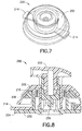
- Figs. 6-8 are views of an integrated ballistic inserter and infusion set 200 in accordance with a third embodiment of the present invention.
- the third exemplary embodiment of the present invention comprises a top 202 and bottom 204. Captured between the top 202 and bottom 204, a body 206 and needle 230 and needle hub 208 are provided.
- the bottom 204 can be provided with an adhesive layer 232 and covering for securing the bottom to a skin surface at the infusion site.
- the needle 230 can preferably comprise a stainless steel or plastic needle or cannula, between 25 gauge and 36 gauge, provided with a single-bevel, tri-bevel or 5-bevel, and be between 1.0 and 10 mm long, but embodiments are not limited thereto.
- the needle 230 can be bonded to the needle hub 208 with an adhesive, such as a Loctite/UV cured adhesive, or can be over molded with, or threaded into the hub.
- a drive spring 210 is captured between the top 202 of the set 200, and one or more tabs 212 of the needle hub 208, to urge the needle hub 208 toward the skin surface when released.
- the device 200 can further comprise one or more rotary release tabs 214 disposed on the body 206 and extend outward through openings 220 in the top 202 for user access, and prevent movement of the needle hub 208 toward the skin surface until turned by a user.
- the needle hub 208 Prior to activation, the needle hub 208 is held in the up position through contact with the tabs 212 of the hub 208 and the top surface of the body 206. That is, the tabs 212 prevent the hub 208 from entering the body 206 until rotationally moved into alignment by turning the rotary tabs 214 of the body 206. In this position, the spring 210 is compressed between the top 202 of the set 200, and tabs 212 of the needle hub 208. Turning the rotary release tabs 214 on the body 206 serves to align one or more of the tabs 212 or other protrusions of the needle hub 208 with openings 215 in the body 206 which permits the needle hub 208 to pass downward through the body 206.
- the drive spring 210 urges the tabs 212 of the needle hub 208 toward the skin surface and seats the needle (not shown) into a skin surface (not shown). Further, the drive spring 120 is configured to maintain contact with, and prevent retraction or rearward movement of the needle hub 208 after insertion.
- the top 202 and bottom 204 of the set 200 are configured to rotatably lock together using feet 216 of the top 202, and shoulders 218 of the bottom 204. Openings 220 are provided in the top 202 to allow the tabs 214 to extend from within the device for turning the body 206 relative to the hub 208 for alignment and activation.
- a rotatable tube set connector 222 can then be coupled with the top 202 to complete the set.
- the connector 222 can comprise a cylindrical member 224 to engage a similarly shaped opening in the needle hub 208 through an opening in the top 202.
- the cylindrical member 224 can comprise a recess 226 into which an O-ring or other seal (not shown) can be provided.
- a fluid path 225 is established between an infusion pump tube (not shown) and the needle (not shown) via the assembly of the rotatable tube set connector 222 with the set.
- each driving spring 18, 120 and 210 is configured to insert an exemplary needle at a controlled high rate of speed, of 3.3 ft/sec. (1.0 m/sec.) up to and including those greater than 10 ft/sec. (3.0 m/sec.).
- a controlled high rate of speed of 3.3 ft/sec. (1.0 m/sec.) up to and including those greater than 10 ft/sec. (3.0 m/sec.).
- a terminal velocity produces more reliable results for intradermal insertions of short (i.e., 1.5 mm) needle or cannula.
- the spring diameter, pitch, and material all contribute to the spring constant. This constant and the total travel of the spring once released can be manipulated to produce the desired velocity T.
- the free length of the driving spring can be 38 mm, and the rate can be 0.05 N/mm, but embodiments are not limited thereto.
- the needle In the up position, the needle is recessed from the skin surface 1.5 mm, but embodiments are not limited thereto. Therefore, the needle is accelerated by the spring for a distance of 1.5 mm until the tip of the needle comes into contact with the skin.
- the weight of the driven components is 4.1 g.
- the weight of the needle, needle holder, and needle assembly can be considered negligible. Therefore, the speed of the driven components, V, can be calculated at the point the where the needle contacts the skin surface to be:
- the integrated ballistic inserter requires fewer operational steps and requires fewer parts than previously available inserter and set combinations.
- a separate inserter is not needed with these devices, thereby reducing the burden on users to carry the device and the amount of waste generated.
- a removable inserter is not provided with these devices, thereby reducing the risk of movement to the infusion set when removing the inserter.
- the issue of a separate, reusable or disposable inserter is removed by integrating the cannula deployment mechanism into the hub of the device that remains attached to the patient.
- one or more of the exemplary embodiments of the present invention can be provided with a skin contacting adhesive layer and backing. Precise insertion is achieved by first securing the infusion set to the infusion site via the adhesive, which permits the user to activate the integrated ballistic inserter at the proper alignment and insert the needle. In doing so, the needle is driven into the skin surface at a controlled high rate of speed to minimize the risk of tenting at needle insertion. Further, the adhesive at or very near the insertion site secures the skin surface and further minimizes tenting of the skin surface during insertion.
- proper insertion of the infusion set into the delivery site consists of straightforward steps.
- a backing (not shown) is peeled off the skin adhesive layer of the infusion set, and the infusion set is adhered to the skin surface in the area of the desired infusion site.
- the user then releases the driving spring by pulling a tab or rotating an arm, thereby inserting the needle into the skin surface of the infusion site.
- the user can then attach the tube set connection to the set and then prime the infusion set and deliver insulin or other medicament to the infusion site via the attached infusion pump (not shown).
- the integrated ballistic inserter and set ensure proper alignment and positioning.
- Most inserters on the market are either oversized, to ensure an insertion force perpendicular to the skin surface, or are thin and portable, which can lead to misaligned insertion.
- the integrated ballistic inserter by first adhering or "locking" the outer skin adhesive of the infusion set to the skin surface, the integrated ballistic inserter is aligned properly for needle insertion.
- the exemplary embodiments of the present invention can include a relatively small inserter which is properly aligned with the infusion site at a time of use.
- Such a system and method further allows the use of a small intradermal needle, or microneedle, which can be placed perpendicular to the skin surface, and which is isolated from outside forces, thereby maintaining position and causing less pain to the user during use. Still further, by infusing into the intradermal layer of the skin, the exemplary embodiments of the present invention offer the potential for better absorption of the insulin when compared to subcutaneous delivery systems. In doing so, it may be possible for the typical user to both consume less insulin and maintain a better medicament regime. It will be appreciated that multiple needles or microneedles can be used, if desired, in place of a single needle or microneedle.
- intradermal infusion set concepts are at risk of tenting, which is the undesired effect where skin is deflected at or during insertion, creating a shape associated with a tent. In doing so, the skin surface tents during needle insertion rather than needle penetration into the skin.
- the present invention provides a needle which is inserted at a controlled high rate of speed, of 3.3 ft/sec. (1.0 m/sec.) up to and including those greater than 10 ft/sec. (3.0 m/sec.), and wherein the skin surface is secured at the insertion site, the exemplary embodiments of the present invention reduce this risk and ensure more precise needle insertion depth.
- the needle In current steel cannula infusion sets which deliver to the subcutaneous layer, the needle is not isolated from any undesired outside forces which may cause pain when translated to the needle and the needle moves within the skin. Also, other intradermal devices face problems of premature or otherwise undesired needle removal when the device is bumped if the needle is not isolated from the outside forces.
- the intradermal needle is isolated from outside forces by several features.
- the tops are provided to shield the sensitive needle hubs from direct contact with external forces.
- Separate adhesive layers can be used to secure separate elements of the set to the skin surface.
- the tube connection can be rotatable without affecting set adhesion to the skin surface.
- the needle hub is held in the down (lowered or extended) position by the continued presence of the activation spring.
- Proper inserter alignment is accomplished by providing a solid, fixed foundation for the user to release the ballistic inserter drive spring. Such a solid, fixed foundation is provided by the skin adhesive.
- the skin adhesive secures the set at a desired orientation, such that the ballistic inserter is also at a desired orientation of use. Accordingly, precise, repeatable insertions are accomplished via the adhesion.
Landscapes
- Health & Medical Sciences (AREA)
- Vascular Medicine (AREA)
- Engineering & Computer Science (AREA)
- Anesthesiology (AREA)
- Biomedical Technology (AREA)
- Heart & Thoracic Surgery (AREA)
- Hematology (AREA)
- Life Sciences & Earth Sciences (AREA)
- Animal Behavior & Ethology (AREA)
- General Health & Medical Sciences (AREA)
- Public Health (AREA)
- Veterinary Medicine (AREA)
- Infusion, Injection, And Reservoir Apparatuses (AREA)
Applications Claiming Priority (2)
| Application Number | Priority Date | Filing Date | Title |
|---|---|---|---|
| US34496710P | 2010-11-30 | 2010-11-30 | |
| EP11191081.6A EP2457607B1 (fr) | 2010-11-30 | 2011-11-29 | Insertion balistique intégrée activée par ressort pour dispositif de perfusion de médicament |
Related Parent Applications (1)
| Application Number | Title | Priority Date | Filing Date |
|---|---|---|---|
| EP11191081.6A Division EP2457607B1 (fr) | 2010-11-30 | 2011-11-29 | Insertion balistique intégrée activée par ressort pour dispositif de perfusion de médicament |
Publications (3)
| Publication Number | Publication Date |
|---|---|
| EP3184133A1 true EP3184133A1 (fr) | 2017-06-28 |
| EP3184133B1 EP3184133B1 (fr) | 2024-03-06 |
| EP3184133C0 EP3184133C0 (fr) | 2024-03-06 |
Family
ID=45047645
Family Applications (2)
| Application Number | Title | Priority Date | Filing Date |
|---|---|---|---|
| EP17155876.0A Active EP3184133B1 (fr) | 2010-11-30 | 2011-11-29 | Insertion balistique intégrée activée par ressort pour dispositif de perfusion de médicament |
| EP11191081.6A Active EP2457607B1 (fr) | 2010-11-30 | 2011-11-29 | Insertion balistique intégrée activée par ressort pour dispositif de perfusion de médicament |
Family Applications After (1)
| Application Number | Title | Priority Date | Filing Date |
|---|---|---|---|
| EP11191081.6A Active EP2457607B1 (fr) | 2010-11-30 | 2011-11-29 | Insertion balistique intégrée activée par ressort pour dispositif de perfusion de médicament |
Country Status (5)
| Country | Link |
|---|---|
| US (2) | US8795234B2 (fr) |
| EP (2) | EP3184133B1 (fr) |
| JP (3) | JP6545923B2 (fr) |
| CA (2) | CA3030231C (fr) |
| ES (2) | ES2973018T3 (fr) |
Families Citing this family (52)
| Publication number | Priority date | Publication date | Assignee | Title |
|---|---|---|---|---|
| US8834423B2 (en) | 2009-10-23 | 2014-09-16 | University of Pittsburgh—of the Commonwealth System of Higher Education | Dissolvable microneedle arrays for transdermal delivery to human skin |
| CN105536109B (zh) | 2010-02-01 | 2021-04-09 | 贝克顿·迪金森公司 | 低剂量预填充药物输送装置及方法 |
| US8795234B2 (en) * | 2010-11-30 | 2014-08-05 | Becton, Dickinson And Company | Integrated spring-activated ballistic insertion for drug infusion device |
| CA3080222C (fr) * | 2011-02-09 | 2023-06-13 | Becton, Dickinson And Company | Dispositif de perfusion a insertion et retraction automatique d'aiguille d'intubateur |
| US9814832B2 (en) | 2011-09-02 | 2017-11-14 | Unl Holdings Llc | Drive mechanism for drug delivery pumps with integrated status indication |
| US9707335B2 (en) | 2011-09-02 | 2017-07-18 | Unitract Syringe Pty Ltd | Drive mechanism for drug delivery pumps with integrated status indication |
| US11173244B2 (en) | 2011-09-02 | 2021-11-16 | Unl Holdings Llc | Drive mechanism for drug delivery pumps with integrated status indication |
| CA2845379C (fr) | 2011-09-02 | 2019-08-06 | Unitract Syringe Pty Ltd | Mecanisme d'insertion pour une pompe d'administration de medicaments |
| BR112014004530A2 (pt) | 2011-09-02 | 2017-03-28 | Unitract Syringe Pty Ltd | mecanismo de acionamento para bombas de administração de fármaco com indicação de estado integrada |
| MX352613B (es) | 2011-09-13 | 2017-12-01 | Unitract Syringe Pty Ltd | Conexión estéril de vía de fluido para contenedores de fármacos para bombas de suministro de fármacos. |
| WO2013166162A1 (fr) | 2012-05-01 | 2013-11-07 | University Of Pittsburgh - Of The Commonwealth System Of Higher Education | Réseaux de micro-aiguilles à extrémité chargée pour l'insertion transdermique |
| JP6355169B2 (ja) | 2012-08-29 | 2018-07-11 | ユーエヌエル ホールディングス エルエルシーUNL Holdings LLC | 薬剤送達ポンプ用制御送達駆動機構 |
| USD745142S1 (en) | 2012-08-30 | 2015-12-08 | Unitract Syringe Pty Ltd | Drug delivery pump |
| WO2014033898A1 (fr) * | 2012-08-31 | 2014-03-06 | テルモ株式会社 | Seringue |
| US10549079B2 (en) | 2012-12-21 | 2020-02-04 | 3M Innovative Properties Company | Adhesive assemblies and microneedle injection apparatuses comprising same |
| USD723157S1 (en) | 2013-03-12 | 2015-02-24 | Unitract Syringe Pty Ltd | Drug delivery pump |
| CA2898585C (fr) | 2013-01-25 | 2020-10-13 | Unitract Syringe Pty Ltd | Raccordement de trajet de fluide a opercule coulissant integre et recipients pour medicaments pour pompes d'administration de medicaments |
| US9821113B2 (en) * | 2013-03-15 | 2017-11-21 | Becton, Dickinson And Company | Automatic angled infusion set assembly |
| JP6071701B2 (ja) * | 2013-03-29 | 2017-02-01 | 久光製薬株式会社 | アプリケータ |
| AU2014308659B2 (en) | 2013-08-23 | 2018-11-01 | Unl Holdings Llc | Integrated pierceable seal fluid pathway connection and drug containers for drug delivery pumps |
| JP6713467B2 (ja) | 2014-09-29 | 2020-06-24 | ユーエヌエル ホールディングス エルエルシーUNL Holdings LLC | 薬剤送達ポンプの為の剛性針挿入機構 |
| WO2016149673A1 (fr) | 2015-03-18 | 2016-09-22 | University Of Pittsburgh - Of The Commonwealth System Of Higher Education | Composés bioactifs conjugués à des substrats de réseaux de micro-aiguilles |
| WO2017066768A1 (fr) | 2015-10-16 | 2017-04-20 | University Of Pittsburgh-Of The Commonwealth System Of Higher Education | Administration de médicament bioactif multicomposant et libération contrôlée dans la peau par des dispositifs de matrice de micro-aiguilles |
| WO2017120322A1 (fr) | 2016-01-05 | 2017-07-13 | University Of Pittsburgh-Of The Commonwealth System Of Higher Education | Administration ciblant le microenvironnement cutané et visant à renforcer les réponses immunitaires et autres |
| USD806232S1 (en) | 2016-01-21 | 2017-12-26 | Becton, Dickinson And Company | Drug delivery device with insertion mechanism |
| USD829894S1 (en) | 2016-01-21 | 2018-10-02 | Becton, Dickinson And Company | Wearable drug delivery device baseplate |
| USD830547S1 (en) | 2016-01-21 | 2018-10-09 | Becton, Dickinson And Company | Adhesive liner for wearable drug delivery device |
| USD829889S1 (en) | 2016-01-21 | 2018-10-02 | Becton, Dickinson And Company | Wearable drug delivery device with adhesive |
| USD805631S1 (en) | 2016-01-21 | 2017-12-19 | Becton, Dickinson And Company | Drug delivery device with insertion mechanism button safety |
| USD857191S1 (en) | 2016-01-21 | 2019-08-20 | Becton, Dickinson And Company | Wearable drug delivery device |
| USD830537S1 (en) | 2016-01-21 | 2018-10-09 | Becton, Dickinson And Company | Wearable drug delivery device with adhesive and liner |
| JOP20170042B1 (ar) | 2016-02-12 | 2022-09-15 | Amgen Inc | وسيلة توصيل عقار، طريقة تصنيعه وطريقة استخدامه |
| KR101754981B1 (ko) | 2016-02-29 | 2017-07-06 | 중소기업은행 | 약액 주입 장치 |
| JP7074684B2 (ja) | 2016-04-08 | 2022-05-24 | アムジエン・インコーポレーテツド | 薬物送達デバイス、製造方法、及び使用方法 |
| JP2019524302A (ja) | 2016-08-08 | 2019-09-05 | ユーエヌエル ホールディングス エルエルシーUNL Holdings LLC | 薬剤送達デバイスおよび流体流路を接続するための方法 |
| TW201811385A (zh) | 2016-08-30 | 2018-04-01 | 澳洲商優尼揣克注射器有限公司 | 用於藥物遞送泵之受控遞送驅動機構 |
| ES2985905T3 (es) | 2016-11-22 | 2024-11-07 | Lts Device Tech Ltd | Aparato para suministrar una sustancia terapéutica |
| CN121588347A (zh) | 2016-12-16 | 2026-03-03 | 索伦托治疗有限公司 | 用于流体递送装置的施用机构及其使用方法 |
| EP3632487B1 (fr) | 2018-10-05 | 2024-06-12 | LTS Device Technologies Ltd | Déclenchement de séquence |
| EP4643904A3 (fr) | 2019-02-22 | 2026-04-29 | DEKA Products Limited Partnership | Ensemble de perfusion et systèmes et procédés d'ensemble d'insertion |
| US12539361B2 (en) | 2019-02-22 | 2026-02-03 | Deka Products Limited Partnership | Infusion set and inserter assembly apparatuses, systems, and methods |
| CN113490521B (zh) | 2019-02-26 | 2023-05-02 | 贝克顿迪金森法国公司 | 带有帽的自动注射器 |
| KR102615193B1 (ko) | 2019-02-26 | 2023-12-19 | 벡톤 디킨슨 프랑스 | 자동 주사 장치를 위한 낙하 테스트 특징부를 구비한 강성 바늘 쉴드 분리기 |
| CN113474025B (zh) | 2019-02-26 | 2023-12-01 | 贝克顿迪金森法国公司 | 具有声频指示器的自动注射器 |
| AU2020275934B2 (en) | 2019-05-16 | 2025-09-25 | University Of Pittsburgh - Of The Commonwealth System Of Higher Education | Microneedle arrays with undercut features for cutaneous and non-cutaneous drug delivery |
| CA3203623A1 (fr) | 2021-01-05 | 2022-07-14 | Steve BEGUIN | Raccord d'aiguille dote d?un verrouillage a pression pour dispositif d'administration de medicament |
| USD1013864S1 (en) | 2021-08-26 | 2024-02-06 | Deka Products Limited Partnership | Fluid administration apparatus assembly |
| USD1008452S1 (en) | 2021-08-26 | 2023-12-19 | Deka Products Limited Partnership | Lock member |
| USD1090862S1 (en) | 2022-08-26 | 2025-08-26 | Deka Products Limited Partnership | Adhering assembly for medical devices and the like |
| USD1043976S1 (en) | 2022-08-26 | 2024-09-24 | Deka Products Limited Partnership | Fluid transfer connector |
| USD1057941S1 (en) | 2022-08-26 | 2025-01-14 | Deka Products Limited Partnership | Patient care assembly component |
| KR20250136558A (ko) * | 2024-03-08 | 2025-09-16 | 주식회사 케어메디 | 약물 주입 장치의 주입관을 대상체에 삽입시키기 위한 어플리케이터 및 이를 포함하는 약물 주입 시스템 |
Citations (4)
| Publication number | Priority date | Publication date | Assignee | Title |
|---|---|---|---|---|
| US20050101912A1 (en) * | 2003-11-10 | 2005-05-12 | Mark Faust | Device and method for insertion of a cannula of an infusion device |
| US20080319414A1 (en) * | 2007-06-25 | 2008-12-25 | Medingo, Ltd. | Insertion device |
| WO2009039013A1 (fr) * | 2007-09-17 | 2009-03-26 | Icu Medical, Inc. | Dispositifs d'insertion pour dispositifs de perfusion |
| WO2010112521A1 (fr) * | 2009-03-31 | 2010-10-07 | Unomedical A/S | Dispositif introducteur |
Family Cites Families (54)
| Publication number | Priority date | Publication date | Assignee | Title |
|---|---|---|---|---|
| US3572336A (en) * | 1968-04-30 | 1971-03-23 | Daniel R Hershberg | Syringe |
| US3918355A (en) | 1972-08-24 | 1975-11-11 | Robert L Weber | Infusion apparatus and method |
| US4490141A (en) | 1982-08-04 | 1984-12-25 | Becton Dickinson And Company | Catheter stabilizer and method of securing same to a patient |
| CA1283827C (fr) * | 1986-12-18 | 1991-05-07 | Giorgio Cirelli | Dispositif pour l'injection de formules liquides |
| SE9101022D0 (sv) * | 1991-01-09 | 1991-04-08 | Paal Svedman | Medicinsk suganordning |
| US6547764B2 (en) | 2000-05-31 | 2003-04-15 | Novo Nordisk A/S | Double pointed injection needle |
| US7083597B2 (en) | 2001-01-05 | 2006-08-01 | Applied Diabetes Research, Inc. | Pivoting joint infusion system with seal |
| WO2002070037A2 (fr) * | 2001-03-04 | 2002-09-12 | Sterling Medivations, Inc. | Ensemble raccord de perfusion et systeme de deconnexion d'une ligne de fluide |
| WO2002081012A2 (fr) * | 2001-04-06 | 2002-10-17 | Disetronic Licensing Ag | Dispositif de perfusion |
| AUPR620701A0 (en) | 2001-07-06 | 2001-08-02 | Ozone Manufacturing Pty Ltd | Evaporative cooler purifier |
| BRPI0307434B8 (pt) * | 2002-02-04 | 2021-06-22 | Becton Dickinson Co | dispositivo para aplicar ou retirar uma substância através da pele. |
| US8504179B2 (en) | 2002-02-28 | 2013-08-06 | Smiths Medical Asd, Inc. | Programmable medical infusion pump |
| US20080172026A1 (en) | 2006-10-17 | 2008-07-17 | Blomquist Michael L | Insulin pump having a suspension bolus |
| US20040010207A1 (en) * | 2002-07-15 | 2004-01-15 | Flaherty J. Christopher | Self-contained, automatic transcutaneous physiologic sensing system |
| US7591801B2 (en) | 2004-02-26 | 2009-09-22 | Dexcom, Inc. | Integrated delivery device for continuous glucose sensor |
| US7309326B2 (en) * | 2003-11-18 | 2007-12-18 | Icu Medical, Inc. | Infusion set |
| ATE424228T1 (de) | 2004-03-26 | 2009-03-15 | Unomedical As | Infusionsset |
| JP4913723B2 (ja) * | 2004-03-26 | 2012-04-11 | ウノメディカル アクティーゼルスカブ | 注入セット用インジェクタ装置 |
| US20060001551A1 (en) | 2004-06-30 | 2006-01-05 | Ulrich Kraft | Analyte monitoring system with wireless alarm |
| WO2006032692A1 (fr) | 2004-09-22 | 2006-03-30 | Novo Nordisk A/S | Dispositif medical avec moyen d'insertion de canule |
| EP1640029A1 (fr) | 2004-09-24 | 2006-03-29 | Novo Nordisk A/S | Dispositif d'injection avec capuchon |
| US7704229B2 (en) | 2005-02-03 | 2010-04-27 | Medtronic Minimed, Inc. | Insertion device |
| CA2604653A1 (fr) | 2005-04-13 | 2006-10-19 | Glucolight Corporation | Methode de diminution et d'etalonnage de donnees d'une reference croisee d'un glucometre sanguin base sur une tomographie de coherence optique et applications associees |
| FR2884721A1 (fr) * | 2005-04-20 | 2006-10-27 | Becton Dickinson France Soc Pa | Ensemble d'injection et dispositif d'assistance a l'injection |
| US8277415B2 (en) | 2006-08-23 | 2012-10-02 | Medtronic Minimed, Inc. | Infusion medium delivery device and method with drive device for driving plunger in reservoir |
| EP1899450A4 (fr) | 2005-06-24 | 2010-03-24 | Univ Texas | Systemes et procedes faisant appel a des cartouches autonomes comprenant des systemes de detection et des systemes de distribution de fluides |
| EP2474338B1 (fr) | 2005-06-27 | 2013-07-24 | 3M Innovative Properties Company | Dispositif applicateur de réseau de micro-aiguilles |
| ATE480278T1 (de) | 2005-09-12 | 2010-09-15 | Unomedical As | Einfürungssystem für ein infusionsset mit einem ersten und zweiten federeinheit |
| EP1764126B1 (fr) | 2005-09-15 | 2010-07-14 | F.Hoffmann-La Roche Ag | Tête d'injection avec poignée |
| ATE513511T1 (de) | 2005-10-08 | 2011-07-15 | Hoffmann La Roche | Stechsystem |
| CN104162200B (zh) | 2006-02-09 | 2018-03-27 | 德卡产品有限公司 | 外围系统 |
| US8219172B2 (en) | 2006-03-17 | 2012-07-10 | Glt Acquisition Corp. | System and method for creating a stable optical interface |
| WO2007141210A1 (fr) | 2006-06-06 | 2007-12-13 | Novo Nordisk A/S | Ensemble constitué d'un dispositif conçu pour être placé sur la peau et d'un emballage correspondant |
| JP5624321B2 (ja) | 2006-10-26 | 2014-11-12 | コンバテック・テクノロジーズ・インコーポレイテッドConvatec Technologies Inc | 人体からの悪臭物質輸送用シリコーンベースチューブ |
| US7988674B2 (en) | 2006-10-30 | 2011-08-02 | Medtronic, Inc. | Externally releasable body portal anchors and systems |
| US20080167620A1 (en) | 2007-01-09 | 2008-07-10 | Seattle Medical Technologies | Disposable infusion device facilitating tissue fold formation for cannula deployment and method |
| EP2146760B1 (fr) | 2007-04-30 | 2018-10-10 | Medtronic MiniMed, Inc. | Remplissage de réservoir, gestion des bulles d'air, et systèmes et procédés d'administration de milieu de perfusion associés |
| GB2445437B (en) | 2007-07-06 | 2008-11-26 | Applied Medical Technology Ltd | Cannula insertion device |
| NZ582422A (en) | 2007-07-18 | 2011-11-25 | Unomedical As | Controlled acceleration device for inserting a penetrating member into a patient |
| AR070764A1 (es) | 2007-12-07 | 2010-05-05 | Pyng Medical Corp | Aparatos y metodos para introducir portales oseos |
| US8540673B2 (en) | 2008-03-18 | 2013-09-24 | Calibra Medical, Inc. | Disposable infusion device with actuation lock-out |
| CA2670856A1 (fr) | 2008-06-30 | 2009-12-30 | Animas Corporation | Micropompe volumetrique |
| JP5125876B2 (ja) | 2008-08-20 | 2013-01-23 | ニプロ株式会社 | 挿入装置 |
| US8310415B2 (en) | 2008-09-30 | 2012-11-13 | Animas Corporation | Medical devices using bistable displays |
| EP2198778B1 (fr) | 2008-12-19 | 2013-07-03 | F. Hoffmann-La Roche AG | Dispositif de perfuseur avec mesure d'impédance |
| EP2229967B1 (fr) | 2009-03-17 | 2020-04-15 | F.Hoffmann-La Roche Ag | Ensemble de canule et système de perfusion ambulatoire avec un capteur de pression fabriqué à partir de couches coplanaires superposées |
| US20120283540A1 (en) | 2009-08-08 | 2012-11-08 | Sanofi-Aventis Deutschland Gmbh | Implantable sensor device and medical delivery device connectable to such a sensor device |
| EP2470242B1 (fr) | 2009-08-27 | 2017-12-06 | Sanofi-Aventis Deutschland GmbH | Conteneur de médicaments |
| JP5701882B2 (ja) | 2009-09-10 | 2015-04-15 | サノフィ−アベンティス・ドイチュラント・ゲゼルシャフト・ミット・ベシュレンクテル・ハフツング | 薬剤容器 |
| DK2493538T3 (en) | 2009-10-30 | 2016-05-02 | Hoffmann La Roche | Systems, methods and devices for adjustment of feeding depth of safety device associated with a portable therapeutic device |
| DK2506914T3 (en) | 2009-11-30 | 2018-12-10 | Hoffmann La Roche | ANALYSIS MONITORING AND FLUID SUBMISSION SYSTEM |
| EP2560703A2 (fr) | 2010-04-20 | 2013-02-27 | MiniPumps, LLC | Dispositifs de pompes à médicaments à commande électrolytique |
| WO2012048150A1 (fr) | 2010-10-06 | 2012-04-12 | Profusa, Inc. | Capteurs d'intégration de tissu |
| US8795234B2 (en) * | 2010-11-30 | 2014-08-05 | Becton, Dickinson And Company | Integrated spring-activated ballistic insertion for drug infusion device |
-
2011
- 2011-11-22 US US13/302,956 patent/US8795234B2/en active Active
- 2011-11-29 EP EP17155876.0A patent/EP3184133B1/fr active Active
- 2011-11-29 CA CA3030231A patent/CA3030231C/fr active Active
- 2011-11-29 CA CA2759577A patent/CA2759577C/fr active Active
- 2011-11-29 EP EP11191081.6A patent/EP2457607B1/fr active Active
- 2011-11-29 ES ES17155876T patent/ES2973018T3/es active Active
- 2011-11-29 ES ES11191081.6T patent/ES2628142T3/es active Active
- 2011-11-30 JP JP2011262078A patent/JP6545923B2/ja active Active
-
2014
- 2014-06-30 US US14/320,485 patent/US9981084B2/en active Active
-
2017
- 2017-07-14 JP JP2017138312A patent/JP6752760B2/ja active Active
-
2020
- 2020-05-25 JP JP2020090662A patent/JP7203789B2/ja active Active
Patent Citations (4)
| Publication number | Priority date | Publication date | Assignee | Title |
|---|---|---|---|---|
| US20050101912A1 (en) * | 2003-11-10 | 2005-05-12 | Mark Faust | Device and method for insertion of a cannula of an infusion device |
| US20080319414A1 (en) * | 2007-06-25 | 2008-12-25 | Medingo, Ltd. | Insertion device |
| WO2009039013A1 (fr) * | 2007-09-17 | 2009-03-26 | Icu Medical, Inc. | Dispositifs d'insertion pour dispositifs de perfusion |
| WO2010112521A1 (fr) * | 2009-03-31 | 2010-10-07 | Unomedical A/S | Dispositif introducteur |
Also Published As
| Publication number | Publication date |
|---|---|
| US20120136310A1 (en) | 2012-05-31 |
| EP3184133B1 (fr) | 2024-03-06 |
| US20140316337A1 (en) | 2014-10-23 |
| US8795234B2 (en) | 2014-08-05 |
| US9981084B2 (en) | 2018-05-29 |
| JP2012115672A (ja) | 2012-06-21 |
| JP2017185331A (ja) | 2017-10-12 |
| CA3030231A1 (fr) | 2012-05-30 |
| EP2457607A1 (fr) | 2012-05-30 |
| CA3030231C (fr) | 2021-02-09 |
| JP7203789B2 (ja) | 2023-01-13 |
| JP2020127834A (ja) | 2020-08-27 |
| JP6545923B2 (ja) | 2019-07-17 |
| EP3184133C0 (fr) | 2024-03-06 |
| JP6752760B2 (ja) | 2020-09-09 |
| CA2759577C (fr) | 2019-11-12 |
| ES2973018T3 (es) | 2024-06-18 |
| ES2628142T3 (es) | 2017-08-01 |
| EP2457607B1 (fr) | 2017-03-15 |
| CA2759577A1 (fr) | 2012-05-30 |
Similar Documents
| Publication | Publication Date | Title |
|---|---|---|
| EP2457607B1 (fr) | Insertion balistique intégrée activée par ressort pour dispositif de perfusion de médicament | |
| EP2457606B1 (fr) | Ensemble de perfusion dermique de pompe à insuline doté d'une insertion de canule mécanisée et en partie intégrée, dotée d'une partie d'activation jetable | |
| EP2457603B1 (fr) | Dispositif de perfusion à micro-aiguille balistique | |
| EP2968891B1 (fr) | Ensemble de tubulure de perfusion coudée automatique | |
| EP3459574B1 (fr) | Introducteur incliné activé par glissement pour une perfusion de médicament par voie intradermique | |
| US20140058353A1 (en) | Subcutaneous Infusion Device |
Legal Events
| Date | Code | Title | Description |
|---|---|---|---|
| PUAI | Public reference made under article 153(3) epc to a published international application that has entered the european phase |
Free format text: ORIGINAL CODE: 0009012 |
|
| STAA | Information on the status of an ep patent application or granted ep patent |
Free format text: STATUS: THE APPLICATION HAS BEEN PUBLISHED |
|
| AC | Divisional application: reference to earlier application |
Ref document number: 2457607 Country of ref document: EP Kind code of ref document: P |
|
| AK | Designated contracting states |
Kind code of ref document: A1 Designated state(s): AL AT BE BG CH CY CZ DE DK EE ES FI FR GB GR HR HU IE IS IT LI LT LU LV MC MK MT NL NO PL PT RO RS SE SI SK SM TR |
|
| STAA | Information on the status of an ep patent application or granted ep patent |
Free format text: STATUS: REQUEST FOR EXAMINATION WAS MADE |
|
| 17P | Request for examination filed |
Effective date: 20171122 |
|
| RBV | Designated contracting states (corrected) |
Designated state(s): AL AT BE BG CH CY CZ DE DK EE ES FI FR GB GR HR HU IE IS IT LI LT LU LV MC MK MT NL NO PL PT RO RS SE SI SK SM TR |
|
| STAA | Information on the status of an ep patent application or granted ep patent |
Free format text: STATUS: EXAMINATION IS IN PROGRESS |
|
| 17Q | First examination report despatched |
Effective date: 20190806 |
|
| RIN1 | Information on inventor provided before grant (corrected) |
Inventor name: IRWIN, STEPHEN JAMES Inventor name: KADAMUS, CHRISTOPHER JAMES Inventor name: BENE, ERIC Inventor name: ROUX, SERGE |
|
| GRAP | Despatch of communication of intention to grant a patent |
Free format text: ORIGINAL CODE: EPIDOSNIGR1 |
|
| STAA | Information on the status of an ep patent application or granted ep patent |
Free format text: STATUS: GRANT OF PATENT IS INTENDED |
|
| INTG | Intention to grant announced |
Effective date: 20231011 |
|
| RAP3 | Party data changed (applicant data changed or rights of an application transferred) |
Owner name: BECTON, DICKINSON AND COMPANY |
|
| GRAS | Grant fee paid |
Free format text: ORIGINAL CODE: EPIDOSNIGR3 |
|
| GRAA | (expected) grant |
Free format text: ORIGINAL CODE: 0009210 |
|
| STAA | Information on the status of an ep patent application or granted ep patent |
Free format text: STATUS: THE PATENT HAS BEEN GRANTED |
|
| AC | Divisional application: reference to earlier application |
Ref document number: 2457607 Country of ref document: EP Kind code of ref document: P |
|
| AK | Designated contracting states |
Kind code of ref document: B1 Designated state(s): AL AT BE BG CH CY CZ DE DK EE ES FI FR GB GR HR HU IE IS IT LI LT LU LV MC MK MT NL NO PL PT RO RS SE SI SK SM TR |
|
| REG | Reference to a national code |
Ref country code: GB Ref legal event code: FG4D |
|
| REG | Reference to a national code |
Ref country code: CH Ref legal event code: EP |
|
| REG | Reference to a national code |
Ref country code: IE Ref legal event code: FG4D |
|
| REG | Reference to a national code |
Ref country code: DE Ref legal event code: R096 Ref document number: 602011074627 Country of ref document: DE |
|
| U01 | Request for unitary effect filed |
Effective date: 20240402 |
|
| U07 | Unitary effect registered |
Designated state(s): AT BE BG DE DK EE FI FR IT LT LU LV MT NL PT SE SI Effective date: 20240411 |
|
| REG | Reference to a national code |
Ref country code: ES Ref legal event code: FG2A Ref document number: 2973018 Country of ref document: ES Kind code of ref document: T3 Effective date: 20240618 |
|
| PG25 | Lapsed in a contracting state [announced via postgrant information from national office to epo] |
Ref country code: GR Free format text: LAPSE BECAUSE OF FAILURE TO SUBMIT A TRANSLATION OF THE DESCRIPTION OR TO PAY THE FEE WITHIN THE PRESCRIBED TIME-LIMIT Effective date: 20240607 |
|
| PG25 | Lapsed in a contracting state [announced via postgrant information from national office to epo] |
Ref country code: HR Free format text: LAPSE BECAUSE OF FAILURE TO SUBMIT A TRANSLATION OF THE DESCRIPTION OR TO PAY THE FEE WITHIN THE PRESCRIBED TIME-LIMIT Effective date: 20240306 Ref country code: RS Free format text: LAPSE BECAUSE OF FAILURE TO SUBMIT A TRANSLATION OF THE DESCRIPTION OR TO PAY THE FEE WITHIN THE PRESCRIBED TIME-LIMIT Effective date: 20240606 |
|
| PG25 | Lapsed in a contracting state [announced via postgrant information from national office to epo] |
Ref country code: RS Free format text: LAPSE BECAUSE OF FAILURE TO SUBMIT A TRANSLATION OF THE DESCRIPTION OR TO PAY THE FEE WITHIN THE PRESCRIBED TIME-LIMIT Effective date: 20240606 Ref country code: NO Free format text: LAPSE BECAUSE OF FAILURE TO SUBMIT A TRANSLATION OF THE DESCRIPTION OR TO PAY THE FEE WITHIN THE PRESCRIBED TIME-LIMIT Effective date: 20240606 Ref country code: HR Free format text: LAPSE BECAUSE OF FAILURE TO SUBMIT A TRANSLATION OF THE DESCRIPTION OR TO PAY THE FEE WITHIN THE PRESCRIBED TIME-LIMIT Effective date: 20240306 Ref country code: GR Free format text: LAPSE BECAUSE OF FAILURE TO SUBMIT A TRANSLATION OF THE DESCRIPTION OR TO PAY THE FEE WITHIN THE PRESCRIBED TIME-LIMIT Effective date: 20240607 |
|
| PG25 | Lapsed in a contracting state [announced via postgrant information from national office to epo] |
Ref country code: IS Free format text: LAPSE BECAUSE OF FAILURE TO SUBMIT A TRANSLATION OF THE DESCRIPTION OR TO PAY THE FEE WITHIN THE PRESCRIBED TIME-LIMIT Effective date: 20240706 |
|
| PG25 | Lapsed in a contracting state [announced via postgrant information from national office to epo] |
Ref country code: SM Free format text: LAPSE BECAUSE OF FAILURE TO SUBMIT A TRANSLATION OF THE DESCRIPTION OR TO PAY THE FEE WITHIN THE PRESCRIBED TIME-LIMIT Effective date: 20240306 |
|
| PG25 | Lapsed in a contracting state [announced via postgrant information from national office to epo] |
Ref country code: CZ Free format text: LAPSE BECAUSE OF FAILURE TO SUBMIT A TRANSLATION OF THE DESCRIPTION OR TO PAY THE FEE WITHIN THE PRESCRIBED TIME-LIMIT Effective date: 20240306 |
|
| PG25 | Lapsed in a contracting state [announced via postgrant information from national office to epo] |
Ref country code: PL Free format text: LAPSE BECAUSE OF FAILURE TO SUBMIT A TRANSLATION OF THE DESCRIPTION OR TO PAY THE FEE WITHIN THE PRESCRIBED TIME-LIMIT Effective date: 20240306 |
|
| PG25 | Lapsed in a contracting state [announced via postgrant information from national office to epo] |
Ref country code: SK Free format text: LAPSE BECAUSE OF FAILURE TO SUBMIT A TRANSLATION OF THE DESCRIPTION OR TO PAY THE FEE WITHIN THE PRESCRIBED TIME-LIMIT Effective date: 20240306 |
|
| PG25 | Lapsed in a contracting state [announced via postgrant information from national office to epo] |
Ref country code: SM Free format text: LAPSE BECAUSE OF FAILURE TO SUBMIT A TRANSLATION OF THE DESCRIPTION OR TO PAY THE FEE WITHIN THE PRESCRIBED TIME-LIMIT Effective date: 20240306 Ref country code: SK Free format text: LAPSE BECAUSE OF FAILURE TO SUBMIT A TRANSLATION OF THE DESCRIPTION OR TO PAY THE FEE WITHIN THE PRESCRIBED TIME-LIMIT Effective date: 20240306 Ref country code: RO Free format text: LAPSE BECAUSE OF FAILURE TO SUBMIT A TRANSLATION OF THE DESCRIPTION OR TO PAY THE FEE WITHIN THE PRESCRIBED TIME-LIMIT Effective date: 20240306 Ref country code: PL Free format text: LAPSE BECAUSE OF FAILURE TO SUBMIT A TRANSLATION OF THE DESCRIPTION OR TO PAY THE FEE WITHIN THE PRESCRIBED TIME-LIMIT Effective date: 20240306 Ref country code: IS Free format text: LAPSE BECAUSE OF FAILURE TO SUBMIT A TRANSLATION OF THE DESCRIPTION OR TO PAY THE FEE WITHIN THE PRESCRIBED TIME-LIMIT Effective date: 20240706 Ref country code: CZ Free format text: LAPSE BECAUSE OF FAILURE TO SUBMIT A TRANSLATION OF THE DESCRIPTION OR TO PAY THE FEE WITHIN THE PRESCRIBED TIME-LIMIT Effective date: 20240306 |
|
| U20 | Renewal fee for the european patent with unitary effect paid |
Year of fee payment: 14 Effective date: 20241022 |
|
| REG | Reference to a national code |
Ref country code: DE Ref legal event code: R097 Ref document number: 602011074627 Country of ref document: DE |
|
| PLBE | No opposition filed within time limit |
Free format text: ORIGINAL CODE: 0009261 |
|
| STAA | Information on the status of an ep patent application or granted ep patent |
Free format text: STATUS: NO OPPOSITION FILED WITHIN TIME LIMIT |
|
| 26N | No opposition filed |
Effective date: 20241209 |
|
| REG | Reference to a national code |
Ref country code: CH Ref legal event code: PL |
|
| PG25 | Lapsed in a contracting state [announced via postgrant information from national office to epo] |
Ref country code: MC Free format text: LAPSE BECAUSE OF FAILURE TO SUBMIT A TRANSLATION OF THE DESCRIPTION OR TO PAY THE FEE WITHIN THE PRESCRIBED TIME-LIMIT Effective date: 20240306 |
|
| REG | Reference to a national code |
Ref country code: CH Ref legal event code: PL |
|
| PG25 | Lapsed in a contracting state [announced via postgrant information from national office to epo] |
Ref country code: CH Free format text: LAPSE BECAUSE OF NON-PAYMENT OF DUE FEES Effective date: 20241130 |
|
| PG25 | Lapsed in a contracting state [announced via postgrant information from national office to epo] |
Ref country code: IE Free format text: LAPSE BECAUSE OF NON-PAYMENT OF DUE FEES Effective date: 20241129 |
|
| U20 | Renewal fee for the european patent with unitary effect paid |
Year of fee payment: 15 Effective date: 20251022 |
|
| PGFP | Annual fee paid to national office [announced via postgrant information from national office to epo] |
Ref country code: GB Payment date: 20251023 Year of fee payment: 15 |
|
| PGFP | Annual fee paid to national office [announced via postgrant information from national office to epo] |
Ref country code: ES Payment date: 20251201 Year of fee payment: 15 |
|
| PG25 | Lapsed in a contracting state [announced via postgrant information from national office to epo] |
Ref country code: HU Free format text: LAPSE BECAUSE OF FAILURE TO SUBMIT A TRANSLATION OF THE DESCRIPTION OR TO PAY THE FEE WITHIN THE PRESCRIBED TIME-LIMIT; INVALID AB INITIO Effective date: 20111129 |
|
| PG25 | Lapsed in a contracting state [announced via postgrant information from national office to epo] |
Ref country code: CY Free format text: LAPSE BECAUSE OF FAILURE TO SUBMIT A TRANSLATION OF THE DESCRIPTION OR TO PAY THE FEE WITHIN THE PRESCRIBED TIME-LIMIT; INVALID AB INITIO Effective date: 20111129 |